US11513594B2 - Method for operating a pair of smart glasses - Google Patents
Method for operating a pair of smart glasses Download PDFInfo
- Publication number
- US11513594B2 US11513594B2 US17/336,849 US202117336849A US11513594B2 US 11513594 B2 US11513594 B2 US 11513594B2 US 202117336849 A US202117336849 A US 202117336849A US 11513594 B2 US11513594 B2 US 11513594B2
- Authority
- US
- United States
- Prior art keywords
- eye
- laser beam
- optical path
- path length
- input unit
- Prior art date
- Legal status (The legal status is an assumption and is not a legal conclusion. Google has not performed a legal analysis and makes no representation as to the accuracy of the status listed.)
- Active
Links
Images


Classifications
-
- G—PHYSICS
- G06—COMPUTING OR CALCULATING; COUNTING
- G06F—ELECTRIC DIGITAL DATA PROCESSING
- G06F3/00—Input arrangements for transferring data to be processed into a form capable of being handled by the computer; Output arrangements for transferring data from processing unit to output unit, e.g. interface arrangements
- G06F3/01—Input arrangements or combined input and output arrangements for interaction between user and computer
- G06F3/011—Arrangements for interaction with the human body, e.g. for user immersion in virtual reality
- G06F3/013—Eye tracking input arrangements
-
- G—PHYSICS
- G02—OPTICS
- G02B—OPTICAL ELEMENTS, SYSTEMS OR APPARATUS
- G02B27/00—Optical systems or apparatus not provided for by any of the groups G02B1/00 - G02B26/00, G02B30/00
- G02B27/0093—Optical systems or apparatus not provided for by any of the groups G02B1/00 - G02B26/00, G02B30/00 with means for monitoring data relating to the user, e.g. head-tracking, eye-tracking
-
- G—PHYSICS
- G02—OPTICS
- G02B—OPTICAL ELEMENTS, SYSTEMS OR APPARATUS
- G02B27/00—Optical systems or apparatus not provided for by any of the groups G02B1/00 - G02B26/00, G02B30/00
- G02B27/01—Head-up displays
- G02B27/017—Head mounted
- G02B27/0172—Head mounted characterised by optical features
-
- G—PHYSICS
- G02—OPTICS
- G02C—SPECTACLES; SUNGLASSES OR GOGGLES INSOFAR AS THEY HAVE THE SAME FEATURES AS SPECTACLES; CONTACT LENSES
- G02C11/00—Non-optical adjuncts; Attachment thereof
- G02C11/10—Electronic devices other than hearing aids
-
- G—PHYSICS
- G06—COMPUTING OR CALCULATING; COUNTING
- G06F—ELECTRIC DIGITAL DATA PROCESSING
- G06F3/00—Input arrangements for transferring data to be processed into a form capable of being handled by the computer; Output arrangements for transferring data from processing unit to output unit, e.g. interface arrangements
- G06F3/01—Input arrangements or combined input and output arrangements for interaction between user and computer
- G06F3/017—Gesture based interaction, e.g. based on a set of recognized hand gestures
-
- G—PHYSICS
- G02—OPTICS
- G02B—OPTICAL ELEMENTS, SYSTEMS OR APPARATUS
- G02B27/00—Optical systems or apparatus not provided for by any of the groups G02B1/00 - G02B26/00, G02B30/00
- G02B27/01—Head-up displays
- G02B27/0101—Head-up displays characterised by optical features
- G02B2027/0118—Head-up displays characterised by optical features comprising devices for improving the contrast of the display / brillance control visibility
-
- G—PHYSICS
- G02—OPTICS
- G02B—OPTICAL ELEMENTS, SYSTEMS OR APPARATUS
- G02B27/00—Optical systems or apparatus not provided for by any of the groups G02B1/00 - G02B26/00, G02B30/00
- G02B27/01—Head-up displays
- G02B27/0101—Head-up displays characterised by optical features
- G02B2027/0147—Head-up displays characterised by optical features comprising a device modifying the resolution of the displayed image
-
- G—PHYSICS
- G02—OPTICS
- G02B—OPTICAL ELEMENTS, SYSTEMS OR APPARATUS
- G02B27/00—Optical systems or apparatus not provided for by any of the groups G02B1/00 - G02B26/00, G02B30/00
- G02B27/01—Head-up displays
- G02B27/017—Head mounted
- G02B2027/0178—Eyeglass type
Definitions
- the present invention relates to a method for operating smart glasses as well as smart glasses.
- eye-tracking or eye detection also known as oculography
- eye detection is used to adjust a control device of a projection unit of the pair of smart glasses, for example in displaying context-sensitive information.
- U.S. Pat. No. 7,637,615 B2 discloses such smart glasses using retina projection and eye tracking based on prism mirrors.
- Known systems for eye tracking are often based on detecting information on the eye position using camera-based systems or electrical or electromagnetic sensors in the region of the eye.
- scanned laser systems are known, which, for example, use micromirrors to scan a laser spot across the eye. All of these systems usually come with high complexity and energy consumption, frequently having limited temporal resolution.
- the method according to the invention having the features of claim 1 is characterized by a particularly energy-saving and cost-effective method of operating a pair of smart glasses having high user convenience.
- This is achieved by a method for operating a pair of smart glasses which comprises an input unit and/or output unit and a gaze detection arrangement.
- the gaze detection arrangement is used to determine any eye movement using the steps of:
- the input unit and/or output unit is operated based on the optical path length and/or the eye velocity.
- Eye movement is considered as any movement of the eye, in particular relative to a head of the user of the smart glasses.
- an eye movement corresponds to a change of viewing direction of the eye.
- the eye movement corresponds preferably to a rotation of the eye, in particular the eyeball, within the eye socket.
- a wavelength-modulated laser beam which is emitted in particular from a wavelength-modulated laser source, is irradiated onto an eye of a user.
- the laser beam is at least partially backscattered at an ocular surface.
- the backscattered radiation is that portion of the radiation scattered at the ocular surface which is parallel to the emitted laser beam, thus being able to interfere therewith. This backscattering portion interferes with the incident laser radiation, i.e. with the laser radiation propagating toward the eye.
- the backscattered portion of the irradiated laser beam may also be referred to as backscattered radiation.
- the laser feedback interferometry is considered as the detection and analysis of the overlap of the irradiated laser beam and its backscattered portion, i.e. a detection and analysis of a resulting interference-radiation.
- an optical path length of the emitted laser beam is determined.
- the optical path length is considered to be the product of a geometric distance covered by the emitted laser beam from the laser source to the surface of the eye and a refractive index of the material present there. This means that if the laser beam is emitted in air (refractive index of approx. 1) from a laser source directly towards the eye, the optical path length is a very good approximation of the distance between the laser source and the eye. For example, if the wavelength of the emitted laser radiation is known, the optical path length can be estimated based on constructive or destructive interference.
- triangle-modulated laser light is emitted as a wavelength-modulated laser beam within the wavelength.
- the optical path length may be determined.
- the Doppler shift can then be used to determine the eye velocity.
- the eye velocity is considered to be a tangential velocity of a point on the ocular surface, this point corresponding to the point where the laser radiation impinges on the ocular surface.
- the eye velocity comprises an absolute value for the current velocity, as well as a direction of the current velocity.
- the input unit and/or output unit is then operated based on the determined optical path length and/or the eye velocity.
- the method thus allows the input unit and/or output unit to be operated by the users eye movement in a particularly simple and efficient manner.
- the specific method of detecting the eye movement using laser feedback interferometry, especially using the Doppler effect has the advantage of particularly high temporal sampling rate, so that the eye movement can be detected in particularly high temporal resolution.
- the method offers the advantage of using simple and inexpensive components and evaluation algorithms, which have low energy requirements. Especially, no computationally intensive image data processing is required.
- moving components, such as scanning devices will not be required, thus providing particularly flexible and robust applicabilities.
- the input unit and/or output unit is activated or deactivated based on optical path length and/or eye velocity. That is, the eye-tracking arrangement is able to initiate activation and/or deactivation of the input unit and/or output unit.
- a deactivated state is a state in which there is no energy consumption of the input unit and/or output unit.
- the gaze detection arrangement directs a single laser beam towards the eye, wherein, based on the optical path length detected, it will be detected when the gaze direction of the eye is aligned such that the single laser beam enters the eye through the pupil.
- the input unit and/or output unit and/or a portion of the eye-tracking arrangement is be operated based on the detected entrance of this single laser beam into the eye.
- the eye-tracking arrangement can thus be set to a sleep mode having reduced energy consumption. Preferably, in this sleep mode only the single laser beam is directed towards the eye.
- the input unit and/or output unit and/or the eye-tracking arrangement can be operated, and for example can be fully activated.
- the individual laser beam may be designed to be visible to the user during the process, such that the user receives respective optical feedback on operation. This may enable for the smart glasses to be operated particularly power-saving and user-friendly.
- an eye gesture is recognized based on the optical path length and/or the eye velocity.
- the input unit and/or output unit will be operated based on a recognized predefined eye gesture.
- the eye gesture may, for example, be any predefined movement pattern of the eye, such as downwards rotation followed by sideways rotation.
- different actions may be performed based on different predefined eye gestures.
- it may be sufficient if relative eye movement is determined by the eye tracking arrangement, wherein, for example, determination of absolute eye position is not required to be able to clearly distinguish the predefined eye gestures.
- the specific high-resolution and energy-saving detection of eye movements using the eye-tracking arrangement may enable particularly efficient and reliable operation of the smart glasses.
- the input unit and/or output unit comprises an image projection unit, which is arranged to project an image onto a retina of the eye.
- an image projection unit which is arranged to project an image onto a retina of the eye.
- image parameters of the image projected by the image projection unit are adjusted based on the determined optical path length and/or eye velocity.
- This enables particularly high image quality of the image visible to the user, wherein specific adaptation of the image parameters means that, for example, regions where lower image quality is sufficient for anatomical reasons may be displayed with little display effort, to obtain especially efficient operation of the smart glasses.
- image sharpness and/or image resolution and/or brightness and/or color distribution of the image projected by the image projection unit will be adjusted.
- these image parameters are adapted across the entire vision field of the user corresponding to the instantaneous viewing angle of the eye.
- the image parameters are adjusted depending on a position of the fovea centralis of the eye, which corresponds to the region of sharpest vision.
- the image projected by the image projection unit is adjusted such that in the region of the fovea higher image sharpness and/or higher image resolution than in the surrounding regions of the vision field exists.
- the image sharpness and/or the image resolution decreases radially outward in the users vision field, especially decreases continuously. This enables efficient operation of the smart glasses, as lower display quality of the image projection unit may be realized in the regions where the visual capacity is pronounced in less detail for anatomical reasons. This results in lower computing effort as well as lower energy consumption in the image projection unit.
- the method further comprises the steps of: detecting a maximum eye velocity during an eye movement, and predicting an eye movement end position based on the maximum eye velocity. Operation of the input unit and/or output unit is thereby performed based on the eye movement end position. Particularly preferably, adjustment of image parameters of the image projected by the image projection unit is performed based on the eye movement end position. In particular, it is thus possible to predict at which position the eye movement stops in the case of rapid eye movements, so-called saccades. Preferably, prediction of the eye movement end position is based on the assumption that the eye performs a uniformly accelerated movement during such an eye movement.
- the second half of the velocity curve may be estimated, especially based on the assumption of mirror symmetry.
- the end point of the eye movement may be estimated.
- determination of the maximum velocity during the eye movement is based on detecting a decreasing eye velocity following an increase of the eye velocity.
- the input unit and/or output unit comprises a sound reproduction unit and/or an electronic user device.
- the electronic user device is preferably provided as a separate device which is connectable to the smart glasses, for example, using wireless connection. This enables particularly flexible use of the smart glasses.
- a lid closure of the eye is detected based on the optical path length and/or the eye velocity.
- the eye velocity determined is the velocity of eyelid closing.
- the eyelid closing may be determined based on a characteristic velocity, and preferably a characteristic direction of the velocity determined by using the eye tracking arrangement.
- detection of the eyelid closure may be used to operate the input unit and/or output unit. For example, a predefined blink pattern or a closing of the eyelid for a predefined period of time may be used to perform any specific action.
- detection of the eye's eyelid closing may be used for fatigue detection.
- particularly broad application of the smart glasses may be provided.
- At least one portion of the eye tracking arrangement is active at all times.
- a particular eye gesture may be performed at any time to operate, especially activate, the input unit and/or output unit, which otherwise may be switched off.
- the input unit and/or output unit can be operated as required, enabling particularly low energy consumption of the smart glasses during its entire operating time. Due to the particularly energy-saving method of gaze detection, it can be operative at all times, for example, without high energy consumption of the smart glasses.
- the method further comprises the step of: detecting a reflectivity of the eye depending on the amplitude and phase position of the radiation backscattered by the eye, thereby, operating the input unit and/or output unit based on the reflectivity.
- this reflectivity-based operation is performed alternatively or in addition to the operation based on the optical path length and/or eye velocity. It is particularly advantageous if an image projection unit is operated based on the determined optical path length and/or the eye velocity and/or based on the reflectivity, especially wherein image parameters of the image projected by the image projection unit are adjusted based on the determined optical path length and/or the eye velocity and/or based on the reflectivity.
- reflectivity especially means the complex reflectivity with amplitude and phase position of the radiation being backscattered by the eye.
- reflectivity By additionally measuring the reflectivity of the eye, it is thus possible to particularly precisely determine the current position of the eye.
- reflectivity significantly and characteristically differs when the laser radiation impinges on different parts of the eye.
- significantly stronger scattering occurs when the laser radiation impinges on the iris of the eye and passes through the cornea.
- determination of the reflectivity may thus be used to determine when anatomical boundaries are moved past the laser beam, which laser beam is especially stationary with respect to a head of the user, during movement of the eye.
- any eye movement may be determined with particular ease and precision, for example serving as a trigger for operating the input unit and/or output unit.
- the invention results in smart glasses comprising an input unit and/or output unit and a gaze detection arrangement.
- the input unit and/or output unit is arranged to receive an input from the user and/or to output an output to the user.
- the gaze detection arrangement comprises a laser device, which is arranged to irradiate at least one laser beam onto an eye, and a control device, which is arranged to operate the laser device.
- the smart glasses are configured to perform the method described above.
- the smart glasses are characterized by a particularly simple and inexpensive configuration having high detection rate of eye movements and a low energy requirement.
- the laser device comprises at least one surface emitter (also called: vertical-cavity surface-emitting laser, or briefly VCSEL) having a photodiode integrated therein.
- a laser device may be used to detect the eye movements with the eye-tracking arrangement having particularly simple, compact and cost-effective design, based on laser feedback interferometry.
- Such a laser device is especially suitable for the detection by means of the self-mixing effect.
- the photodiode is used to directly detect any overlap of radiation emitted and backscattered within the laser cavity.
- the laser device may comprise a plurality of surface emitters, each of which emitting a laser beam.
- the at least one surface emitter having a photodiode integrated therein is arranged on a spectacle frame and/or on a spectacle temple.
- a spectacle frame is especially regarded as a region of the smart glasses that surrounds the spectacle lens
- a spectacle temple is especially regarded as a holding temple that is connected to the spectacle frame, for example extending to an ear of the user.
- several surface emitters having integrated photodiodes can distributedly be arranged around the spectacle lens on the spectacle frame, allowing particularly precise scanning of the eye over its entire range of motion.
- one or more laser sources may be integrated, preferably molded, into the spectacle lens.
- FIG. 1 is a simplified schematic view of a pair of smart glasses according to a first embodiment of the invention
- FIG. 2 is a simplified schematic detailed view of a gaze detection procedure using the smart glasses of FIG. 1 ,
- FIG. 3 is another simplified schematic detailed view of the implementation of gaze detection using the smart glasses of FIG. 1 ,
- FIG. 4 is a simplified schematic representation of measurement data from the smart glasses of FIG. 1 when performing gaze acquisition
- FIG. 5 is another simplified schematic detailed view of the gaze acquisition performance using the smart glasses of FIG. 1
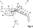
- FIG. 6 is a simplified schematic view of smart glasses according to a second embodiment of the invention.
- FIG. 1 shows a simplified schematic view of a pair of smart glasses 50 according to a first embodiment of the invention.
- the smart glasses 50 comprise a spectacle lens 52 , a spectacle frame 51 in which the spectacle lens 52 is received, and a spectacle temple 53 for holding the smart glasses 50 on a users head.
- the smart glasses 50 are thus configured to be worn on a users head.
- the smart glasses 50 comprise a gaze detection arrangement 20 , by which a gaze direction of an eye 10 of the user may be determined.
- the gaze detection arrangement 20 comprises a laser device 3 and a control device 4 , which is arranged to operate the laser device 4 to perform a corresponding method for detecting the gaze direction of the eye 10 .
- the control device 4 is arranged in the temple 53 of the smart glasses 50 for compact design.
- the laser device 3 includes a total of five surface emitters 3 a , 3 b , 3 c , 3 d , 3 e as laser sources.
- Four of the five surface emitters 3 a , 3 b , 3 c , 3 d are distributedly arranged on the spectacle frame 51 around the spectacle lens 52 .
- a fifth surface emitter 3 e is arranged on the temple 53 .
- Each of the surface emitters 3 a , 3 b , 3 c , 3 d , 3 e is arranged to irradiate a wavelength-modulated laser beam 1 onto the eye 10 . In this case, triangle-modulated laser light is emitted as the laser beam 1 within the wavelength.
- each laser beam 1 is directed in a separate laser spot 30 a , 30 b , 30 c , 30 d , 30 e onto an ocular surface 11 of the eye 10 .
- FIG. 2 shows the laser spots 30 a , 30 b , 30 c , 30 d of the first four surface emitters 3 a , 3 b , 3 c , 3 d arranged on the spectacle frame 51 .
- the fifth laser spot 30 e generated by the fifth surface emitter 3 e is shown on the side of the eye 10 .
- the laser spots 30 a , 30 b , 30 c , 30 d , 30 e are preferably located within a region of the iris 12 of the eye 10 , or in the vicinity of that region.
- the pupil 13 of the eye 10 is often moved close to or through the laser spots 1 , so that the position and movement of the pupil 13 may be determined with high accuracy to determine the gaze direction of the eye with high accuracy.
- the laser beam 1 is initially irradiated onto the eye 10 .
- the laser beam 1 will at least partially be backscattered.
- overlap of the irradiated laser beam 1 with the portion of the backscattered radiation propagating back in parallel in the direction of the surface emitter 3 a occurs.
- a laser feedback interferometry is performed to detect the resulting interference radiation, i.e. overlap of irradiated laser radiation 1 and radiation backscattered in the opposite direction using the photodiode integrated in the surface emitter 3 a .
- detection of the resulting interference radiation is performed by the so-called self-mixing effect.
- FIG. 4 An exemplary frequency spectrum 25 of the resulting interference radiation, which can be detected by means of the integrated photodiode of the surface emitter 3 a , is shown schematically in FIG. 4 .
- the axis 25 a corresponds to the frequency and the axis 25 b to the amplitude.
- the reference number 26 indicates the peak frequency of the detected interference radiation, determined for example by means of a Fourier analysis.
- the peak frequency 26 is dependent on an optical path length 2 .
- the optical path length 2 (cf. FIG. 1 ), corresponds to a distance covered by the laser beam 1 between the surface emitter 3 a and the ocular surface 11 .
- the optical path length 2 corresponds to the shortest distance between the surface emitter 3 a and the eye surface 11 .
- the optical path length 2 may be determined based on laser feedback interferometry for a specific eye position, i.e. for a specific gaze direction.
- FIG. 4 shows an exemplary frequency spectrum 25 , which is being recorded during constant movement of the eye surface 11 in relation to the laser beam 1 , i.e. during rotation of the eye 10 .
- a shift 27 of the peak frequency 26 occurs towards a shifted peak frequency 26 ′ shown as a dashed line, as a result of the Doppler effect.
- the Doppler shift of the emitted and the backscattered laser radiation resulting therefrom can thus be determined based on the frequency spectrum 25 .
- the instantaneous eye velocity of a movement of the eye 10 as well as a direction of the movement can be determined.
- a reflectivity of the eye 10 can be detected based on an amplitude and phase position of the radiation backscattered by the eye 10 .
- reflectivity is defined as the complex reflectivity with amplitude and phase position of the radiation being backscattered by the eye 10 , wherein the reflectivity is different for different regions of the eye 10 .
- the determined reflectivity changes when the laser beam 1 passes anatomical boundaries of the eye 10 , such as the iris 12 or the pupil 13 .
- the reflectivity of the eye 10 can be used to estimate which region of the eye 10 is currently irradiated by the laser beam 1 . Together with the determined optical path length 2 , an instantaneous absolute eye position of the eye 10 can thus be determined.
- any eye movement may be determined using the eye tracking arrangement 20 based on the laser feedback interferometry, wherein any eye movement of the eye 10 may be determined and tracked.
- the instantaneous gaze direction of the eye 10 can be determined. Due to the components required to perform gaze direction determination, particularly high temporal resolution of the gaze direction determination can be achieved with low energy requirements. In addition, particularly low-cost components can be used.
- the pair of smart glasses 50 comprises an input and/or output device 7 , which is configured to output an output to the user.
- the input and/or output device 7 comprises a projection unit, which is arranged to project an image onto a retina of the eye 10 .
- the projection unit can be used, for example, to display an augmented or virtual reality (also: augmented reality AR or virtual reality).
- the projection unit is coupled to the control device 4 , wherein the control device 4 is arranged to operate the projection unit depending on the determined gaze direction.
- the projected image can thereby be adapted depending on the gaze direction.
- image parameters of the image projected by the projection unit are adjusted depending on a position of the optic pit (fovea centralis) of the eye 10 , which corresponds to the region of sharpest vision.
- the position of the optic pit may be determined based on any previous calibration of the eye detection arrangement 20 .
- the image projected by the image projection unit will thus be adapted such that higher image sharpness and higher image resolution are present in the region of the optic pit than in the circumferential regions of the field of vision.
- the image sharpness and/or the image resolution decreases radially outwards with respect to the users field of vision.
- particularly efficient operation of the smart glasses 50 can be provided, as lower display quality of the image projection unit can be realized in the regions where the visual capacity is less pronounced for anatomical reasons. This will result in lower computational effort as well as a particularly low energy requirement for the smart glasses 50 .
- eye gestures can be recognized with the eye tracking arrangement 20 .
- a variety of predefined eye gestures can be assigned to different predetermined actions of the smart glasses 50 .
- an eye gesture may be defined as a predefined sequence of movements of the eye 10 .
- an eye gesture may be a rotation vertically downwards followed by a horizontal rotation to the right. This corresponds to the user first looking downwards and then looking to the right.
- the image projection unit can be operated in a predefined manner.
- the image projection unit can be activated or deactivated to enable operation of the smart glasses 50 as required, and thus in a particularly energy-saving manner.
- the eye gesture can be used to activate operation of menu options of contents displayed in an augmented or virtual reality.
- a particular eye gesture preferably upwards and/or downwards rolling of the eye 10 , activates scrolling of content displayed in the augmented or virtual reality.
- FIG. 5 A particularly simple and energy-saving way of operating the smart glasses 50 is shown in FIG. 5 .
- an operating state of the smart glasses 50 is shown, wherein the input unit and/or output unit 7 is deactivated and the eye tracking arrangement 20 is in a sleep mode.
- the sleep mode only exactly one of the surface emitters 3 b of the gaze detection arrangement 20 is operable, with all other surface emitters 3 a , 3 c , 3 d , 3 e being deactivated.
- the single active surface emitter 3 b only a single laser beam 1 is directed to the eye 10 in exactly one laser port 30 b , as shown in FIG. 5 .
- a simplified eye detection is performed. Specifically, for example only the optical path length 2 is determined. Based on the optical path length 2 , it may be determined when the eye 10 is moved into a position such that the single laser beam 1 can enter the eye 10 through the pupil 13 . This applies to the operating state shown in FIG. 5 when the user looks downwards, i.e., when the eye 10 performs rotation vertically downwards towards the direction A.
- This specific eye gesture i.e. the state when the laser beam 1 enters the eye 10 , is used herein to activate the projection unit as well as the inactive portion of the eye-tracking arrangement 20 .
- a feedback about the activation may be indicated to the user by emitting the single laser beam 1 as a visible light from the surface emitter 3 b.
- FIG. 6 shows a simplified schematic view of a pair of smart glasses 50 according to a second embodiment of the invention.
- the second embodiment essentially corresponds to the first embodiment of FIG. 1 but with the difference of the laser device 3 being alternatively arranged.
- the laser device 3 of the eye tracking arrangement 20 comprises four surface emitters 3 a , 3 b , 3 c , 3 d comprising integrated photodiode, all of which are arranged on the spectacle temple 53 .
- the laser beams 1 emitted by the surface emitters 3 a , 3 b , 3 c , 3 d will thus be indirectly irradiated onto the eye 10 .
- the laser beams 1 are irradiated onto the spectacle lens 52 , exemplified by a focusing point 1 ′ on the spectacle lens 52 .
- a deflection element 54 in the form of a holographic optical element is integrated into the spectacle lens 52 , which deflects the laser beams 1 towards the eye 10 .
- an alternative arrangement of the laser device 3 may be provided, by which the optical path length 2 and the eye velocity may also be efficiently determined as a basis for operating the input unit and/or output unit 7 .
Landscapes
- Engineering & Computer Science (AREA)
- Physics & Mathematics (AREA)
- Theoretical Computer Science (AREA)
- General Engineering & Computer Science (AREA)
- General Physics & Mathematics (AREA)
- Human Computer Interaction (AREA)
- Optics & Photonics (AREA)
- Health & Medical Sciences (AREA)
- Acoustics & Sound (AREA)
- General Health & Medical Sciences (AREA)
- Otolaryngology (AREA)
- Ophthalmology & Optometry (AREA)
- Position Input By Displaying (AREA)
- Optical Radar Systems And Details Thereof (AREA)
Abstract
Description
-
- irradiating an eye using at least one wavelength-modulated laser beam,
- detecting an optical path length of the emitted laser beam based on laser feedback interferometry of the emitted laser beam and radiation backscattered from the eye,
- detecting a Doppler shift, in particular between frequencies, of the emitted and the backscattered radiation based on laser feedback interferometry, and
- detecting an eye velocity based on the Doppler shift,
Claims (15)
Applications Claiming Priority (2)
| Application Number | Priority Date | Filing Date | Title |
|---|---|---|---|
| DE102020206822.4A DE102020206822A1 (en) | 2020-06-02 | 2020-06-02 | Procedure for operating data glasses |
| DE102020206822.4 | 2020-06-02 |
Publications (2)
| Publication Number | Publication Date |
|---|---|
| US20210373659A1 US20210373659A1 (en) | 2021-12-02 |
| US11513594B2 true US11513594B2 (en) | 2022-11-29 |
Family
ID=78508822
Family Applications (1)
| Application Number | Title | Priority Date | Filing Date |
|---|---|---|---|
| US17/336,849 Active US11513594B2 (en) | 2020-06-02 | 2021-06-02 | Method for operating a pair of smart glasses |
Country Status (3)
| Country | Link |
|---|---|
| US (1) | US11513594B2 (en) |
| CN (1) | CN113759545B (en) |
| DE (1) | DE102020206822A1 (en) |
Families Citing this family (13)
| Publication number | Priority date | Publication date | Assignee | Title |
|---|---|---|---|---|
| DE102020206822A1 (en) | 2020-06-02 | 2021-12-02 | Robert Bosch Gesellschaft mit beschränkter Haftung | Procedure for operating data glasses |
| DE102020206821A1 (en) * | 2020-06-02 | 2021-12-02 | Robert Bosch Gesellschaft mit beschränkter Haftung | Method for determining a line of sight of an eye |
| DE102021110109A1 (en) * | 2021-04-21 | 2022-10-27 | Robert Bosch Gesellschaft mit beschränkter Haftung | Method for recognizing eye gestures of an eye |
| GB202107231D0 (en) * | 2021-05-20 | 2021-07-07 | Ams Int Ag | Eye tracking |
| GB202107238D0 (en) * | 2021-05-20 | 2021-07-07 | Ams Int Ag | Eye movement determination |
| DE102021207058A1 (en) | 2021-07-06 | 2023-01-12 | Robert Bosch Gesellschaft mit beschränkter Haftung | Human activity detection method |
| KR20240042461A (en) * | 2021-08-04 | 2024-04-02 | 큐(큐) 리미티드 | Silent voice detection |
| DE102022204107A1 (en) | 2022-04-27 | 2023-11-02 | Robert Bosch Gesellschaft mit beschränkter Haftung | Method and device for determining the viewing direction of an eye and data glasses |
| DE102022208691A1 (en) * | 2022-08-23 | 2024-02-29 | Robert Bosch Gesellschaft mit beschränkter Haftung | Device for monitoring an eye position of a user's eye in a virtual retinal display, data glasses and method |
| DE102022210271A1 (en) * | 2022-09-28 | 2024-03-28 | Robert Bosch Gesellschaft mit beschränkter Haftung | Eye tracking device, data glasses and eye tracking method |
| DE102023203346A1 (en) * | 2023-04-13 | 2024-10-17 | Robert Bosch Gesellschaft mit beschränkter Haftung | Optical device, data glasses and method using the data glasses |
| DE102024204165A1 (en) * | 2024-05-22 | 2025-11-27 | Robert Bosch Gesellschaft mit beschränkter Haftung | Eye tracking device, AR and/or VR headset and eye tracking method |
| DE102024210660A1 (en) * | 2024-11-06 | 2026-05-07 | Robert Bosch Gesellschaft mit beschränkter Haftung | Method for detecting the gaze direction of an eye, control unit and data glasses |
Citations (11)
| Publication number | Priority date | Publication date | Assignee | Title |
|---|---|---|---|---|
| DE102014206626A1 (en) | 2014-04-07 | 2015-10-08 | Bayerische Motoren Werke Aktiengesellschaft | Fatigue detection using data glasses (HMD) |
| DE102014210892A1 (en) | 2014-06-06 | 2015-12-17 | Siemens Aktiengesellschaft | A method of operating an input device and input device controllable by gestures performed with at least one body part of the human body |
| US20160274365A1 (en) * | 2015-03-17 | 2016-09-22 | Thalmic Labs Inc. | Systems, devices, and methods for wearable heads-up displays with heterogeneous display quality |
| US20170131765A1 (en) * | 2015-11-06 | 2017-05-11 | Oculus Vr, Llc | Eye tracking using optical flow |
| US20170261610A1 (en) | 2016-03-11 | 2017-09-14 | Oculus Vr, Llc | Ultrasound/radar for eye tracking |
| US20190043392A1 (en) | 2018-01-05 | 2019-02-07 | Intel Corporation | Augmented reality eyebox fitting optimization for individuals |
| US20190163266A1 (en) | 2016-07-05 | 2019-05-30 | Siemens Aktiengesellschaft | Interaction system and method |
| US20200026350A1 (en) * | 2018-07-20 | 2020-01-23 | Avegant Corp. | Relative Position Based Eye-tracking System |
| DE102018214637A1 (en) | 2018-08-29 | 2020-03-05 | Robert Bosch Gmbh | Method for determining a direction of view of an eye |
| US20200285058A1 (en) * | 2019-03-06 | 2020-09-10 | Suguru Sangu | Optical device, retinal projection display, head-mounted display, and optometric apparatus |
| US20210373659A1 (en) | 2020-06-02 | 2021-12-02 | Robert Bosch Gmbh | Method for operating a pair of smart glasses |
Family Cites Families (9)
| Publication number | Priority date | Publication date | Assignee | Title |
|---|---|---|---|---|
| CA2561287C (en) * | 2004-04-01 | 2017-07-11 | William C. Torch | Biosensors, communicators, and controllers monitoring eye movement and methods for using them |
| JP4608996B2 (en) | 2004-08-19 | 2011-01-12 | ブラザー工業株式会社 | Pupil detection device and image display device including the same |
| FR2945435B1 (en) * | 2009-05-12 | 2012-12-14 | Essilor Int | PAIR OF OPHTHALMIC GLASSES SUITABLE FOR CHARACTERIZING A DIRECTION OF LOOKING AT A BEARER. |
| JP5400481B2 (en) * | 2009-06-03 | 2014-01-29 | 株式会社トプコン | Optical image measuring device |
| US9183612B2 (en) * | 2013-09-04 | 2015-11-10 | Qualcomm Incorporated | Wearable display device use-based data processing control |
| WO2016105282A1 (en) * | 2014-12-26 | 2016-06-30 | Koc University | Near-to-eye display device with spatial light modulator and pupil tracker |
| DE102016218290A1 (en) * | 2016-07-15 | 2018-01-18 | Carl Zeiss Meditec Ag | Method for the highly sensitive measurement of distances and angles in the human eye |
| CA3042263A1 (en) * | 2016-11-10 | 2018-05-17 | Magic Leap, Inc. | Method and system for eye tracking using speckle patterns |
| CN109613790B (en) * | 2018-11-19 | 2024-10-29 | 成都理想境界科技有限公司 | Laser projection optical module and near-eye display device |
-
2020
- 2020-06-02 DE DE102020206822.4A patent/DE102020206822A1/en active Pending
-
2021
- 2021-05-31 CN CN202110599605.7A patent/CN113759545B/en active Active
- 2021-06-02 US US17/336,849 patent/US11513594B2/en active Active
Patent Citations (12)
| Publication number | Priority date | Publication date | Assignee | Title |
|---|---|---|---|---|
| DE102014206626A1 (en) | 2014-04-07 | 2015-10-08 | Bayerische Motoren Werke Aktiengesellschaft | Fatigue detection using data glasses (HMD) |
| DE102014210892A1 (en) | 2014-06-06 | 2015-12-17 | Siemens Aktiengesellschaft | A method of operating an input device and input device controllable by gestures performed with at least one body part of the human body |
| US20160274365A1 (en) * | 2015-03-17 | 2016-09-22 | Thalmic Labs Inc. | Systems, devices, and methods for wearable heads-up displays with heterogeneous display quality |
| US20170131765A1 (en) * | 2015-11-06 | 2017-05-11 | Oculus Vr, Llc | Eye tracking using optical flow |
| US20170261610A1 (en) | 2016-03-11 | 2017-09-14 | Oculus Vr, Llc | Ultrasound/radar for eye tracking |
| US20190163266A1 (en) | 2016-07-05 | 2019-05-30 | Siemens Aktiengesellschaft | Interaction system and method |
| US20190043392A1 (en) | 2018-01-05 | 2019-02-07 | Intel Corporation | Augmented reality eyebox fitting optimization for individuals |
| US20200026350A1 (en) * | 2018-07-20 | 2020-01-23 | Avegant Corp. | Relative Position Based Eye-tracking System |
| DE102018214637A1 (en) | 2018-08-29 | 2020-03-05 | Robert Bosch Gmbh | Method for determining a direction of view of an eye |
| US20210271320A1 (en) | 2018-08-29 | 2021-09-02 | Robert Bosch Gmbh | Method for ascertaining a viewing direction of an eye |
| US20200285058A1 (en) * | 2019-03-06 | 2020-09-10 | Suguru Sangu | Optical device, retinal projection display, head-mounted display, and optometric apparatus |
| US20210373659A1 (en) | 2020-06-02 | 2021-12-02 | Robert Bosch Gmbh | Method for operating a pair of smart glasses |
Non-Patent Citations (4)
| Title |
|---|
| Giuliani, Guido, et al., "Laser diode self-mixing technique for sensing applications", Journal of Optics A: Pure and Applied Optics, (2002), pp. S283-S294. |
| Pruijmboom, Armand, et al., "VCSEL-based miniature laser-Doppler interferometer", International Society for Optics and Photonics, (2008) vol. 6908, 69080I, 7 pages. |
| Search Report from corresponding DE Application No. 10 2020 206 821.6 dated Feb. 11, 2021, 7 pages. |
| Search Report from corresponding DE Application No. 102020206822.4, dated Feb. 11, 2021, 8 pages. |
Also Published As
| Publication number | Publication date |
|---|---|
| CN113759545B (en) | 2025-02-25 |
| CN113759545A (en) | 2021-12-07 |
| US20210373659A1 (en) | 2021-12-02 |
| DE102020206822A1 (en) | 2021-12-02 |
Similar Documents
| Publication | Publication Date | Title |
|---|---|---|
| US11513594B2 (en) | Method for operating a pair of smart glasses | |
| US11435578B2 (en) | Method for detecting a gaze direction of an eye | |
| US11733774B2 (en) | Eye-tracking arrangement | |
| JP7703134B2 (en) | Event Camera System for Pupil Detection and Eye Tracking | |
| US11567570B2 (en) | Relative position based eye-tracking system | |
| JP5689874B2 (en) | Gaze control device, ophthalmic device, method of operating gaze control device for ophthalmic device for controlling eye gaze, computer program or evaluation unit | |
| US20240176136A1 (en) | Method for detecting gestures of an eye | |
| US12474773B2 (en) | Eye movement determination | |
| US20240151966A1 (en) | Method for operating a pair of smart glasses and smart glasses | |
| EP2731049A1 (en) | Eye-tracker | |
| US20230122222A1 (en) | Device, system, and method for biometrically identifying a user of a device | |
| Meyer et al. | A highly integrated ambient light robust eye-tracking sensor for retinal projection ar glasses based on laser feedback interferometry | |
| JP6501444B2 (en) | Electronic device comprising a projection device, in particular a communication device, and method of operating the electronic device | |
| US11675427B2 (en) | Eye tracking based on imaging eye features and assistance of structured illumination probe light | |
| CN110603513B (en) | Eye tracking device and method for tracking eyes using optical imaging | |
| CN121359071A (en) | Pupil detection methods, pupil detection equipment, and data glasses | |
| US20240219999A1 (en) | Optical system for a virtual retina display and a gesture detection of a user of the virtual retina display | |
| KR20250120973A (en) | Tracking system using differential cameras | |
| Meyer et al. | Ambient Light Robust Eye-Tracking for Smart Glasses Using Laser Feedback Interferometry Sensors with Elongated Laser Beams | |
| EP4696222A1 (en) | Gaze fixation system for an ophthalmic imaging instrument | |
| EP4696220A1 (en) | Patient alignment system for an ophthalmic imaging instrument | |
| WO2024208689A1 (en) | Eye tracking device and method of tracking an eye rotation | |
| CN121587661A (en) | Patient alignment system for ophthalmic imaging instrument |
Legal Events
| Date | Code | Title | Description |
|---|---|---|---|
| FEPP | Fee payment procedure |
Free format text: ENTITY STATUS SET TO UNDISCOUNTED (ORIGINAL EVENT CODE: BIG.); ENTITY STATUS OF PATENT OWNER: LARGE ENTITY |
|
| AS | Assignment |
Owner name: ROBERT BOSCH GMBH, GERMANY Free format text: ASSIGNMENT OF ASSIGNORS INTEREST;ASSIGNORS:PETERSEN, ANDREAS;SCHLEBUSCH, THOMAS ALEXANDER;MEYER, JOHANNES;AND OTHERS;SIGNING DATES FROM 20210519 TO 20210601;REEL/FRAME:056909/0170 |
|
| AS | Assignment |
Owner name: TRUMPF PHOTONIC COMPONENTS GMBH, GERMANY Free format text: ASSIGNMENT OF ASSIGNORS INTEREST;ASSIGNOR:ROBERT BOSCH GMBH;REEL/FRAME:056929/0808 Effective date: 20210625 |
|
| STPP | Information on status: patent application and granting procedure in general |
Free format text: DOCKETED NEW CASE - READY FOR EXAMINATION |
|
| STPP | Information on status: patent application and granting procedure in general |
Free format text: NON FINAL ACTION MAILED |
|
| STPP | Information on status: patent application and granting procedure in general |
Free format text: RESPONSE TO NON-FINAL OFFICE ACTION ENTERED AND FORWARDED TO EXAMINER |
|
| STPP | Information on status: patent application and granting procedure in general |
Free format text: FINAL REJECTION MAILED |
|
| STPP | Information on status: patent application and granting procedure in general |
Free format text: DOCKETED NEW CASE - READY FOR EXAMINATION |
|
| STPP | Information on status: patent application and granting procedure in general |
Free format text: NOTICE OF ALLOWANCE MAILED -- APPLICATION RECEIVED IN OFFICE OF PUBLICATIONS |
|
| STPP | Information on status: patent application and granting procedure in general |
Free format text: PUBLICATIONS -- ISSUE FEE PAYMENT VERIFIED |
|
| STCF | Information on status: patent grant |
Free format text: PATENTED CASE |