US11512486B2 - House structure with expandable function - Google Patents
House structure with expandable function Download PDFInfo
- Publication number
- US11512486B2 US11512486B2 US16/904,591 US202016904591A US11512486B2 US 11512486 B2 US11512486 B2 US 11512486B2 US 202016904591 A US202016904591 A US 202016904591A US 11512486 B2 US11512486 B2 US 11512486B2
- Authority
- US
- United States
- Prior art keywords
- chassis
- multifunctional
- deck
- house
- house structure
- Prior art date
- Legal status (The legal status is an assumption and is not a legal conclusion. Google has not performed a legal analysis and makes no representation as to the accuracy of the status listed.)
- Active, expires
Links
Images


Classifications
-
- E—FIXED CONSTRUCTIONS
- E04—BUILDING
- E04H—BUILDINGS OR LIKE STRUCTURES FOR PARTICULAR PURPOSES; SWIMMING OR SPLASH BATHS OR POOLS; MASTS; FENCING; TENTS OR CANOPIES, IN GENERAL
- E04H1/00—Buildings or groups of buildings for dwelling or office purposes; General layout, e.g. modular co-ordination or staggered storeys
- E04H1/005—Modulation co-ordination
-
- G—PHYSICS
- G05—CONTROLLING; REGULATING
- G05D—SYSTEMS FOR CONTROLLING OR REGULATING NON-ELECTRIC VARIABLES
- G05D1/00—Control of position, course, altitude or attitude of land, water, air or space vehicles, e.g. using automatic pilots
- G05D1/02—Control of position or course in two dimensions
- G05D1/021—Control of position or course in two dimensions specially adapted to land vehicles
- G05D1/0231—Control of position or course in two dimensions specially adapted to land vehicles using optical position detecting means
- G05D1/0246—Control of position or course in two dimensions specially adapted to land vehicles using optical position detecting means using a video camera in combination with image processing means
- G05D1/0248—Control of position or course in two dimensions specially adapted to land vehicles using optical position detecting means using a video camera in combination with image processing means in combination with a laser
-
- E—FIXED CONSTRUCTIONS
- E04—BUILDING
- E04H—BUILDINGS OR LIKE STRUCTURES FOR PARTICULAR PURPOSES; SWIMMING OR SPLASH BATHS OR POOLS; MASTS; FENCING; TENTS OR CANOPIES, IN GENERAL
- E04H1/00—Buildings or groups of buildings for dwelling or office purposes; General layout, e.g. modular co-ordination or staggered storeys
- E04H1/02—Dwelling houses; Buildings for temporary habitation, e.g. summer houses
-
- E—FIXED CONSTRUCTIONS
- E04—BUILDING
- E04B—GENERAL BUILDING CONSTRUCTIONS; WALLS, e.g. PARTITIONS; ROOFS; FLOORS; CEILINGS; INSULATION OR OTHER PROTECTION OF BUILDINGS
- E04B1/00—Constructions in general; Structures which are not restricted either to walls, e.g. partitions, or floors or ceilings or roofs
- E04B1/343—Structures characterised by movable, separable, or collapsible parts, e.g. for transport
-
- E—FIXED CONSTRUCTIONS
- E04—BUILDING
- E04H—BUILDINGS OR LIKE STRUCTURES FOR PARTICULAR PURPOSES; SWIMMING OR SPLASH BATHS OR POOLS; MASTS; FENCING; TENTS OR CANOPIES, IN GENERAL
- E04H1/00—Buildings or groups of buildings for dwelling or office purposes; General layout, e.g. modular co-ordination or staggered storeys
- E04H1/02—Dwelling houses; Buildings for temporary habitation, e.g. summer houses
- E04H1/04—Apartment houses arranged in two or more levels
-
- E—FIXED CONSTRUCTIONS
- E04—BUILDING
- E04H—BUILDINGS OR LIKE STRUCTURES FOR PARTICULAR PURPOSES; SWIMMING OR SPLASH BATHS OR POOLS; MASTS; FENCING; TENTS OR CANOPIES, IN GENERAL
- E04H14/00—Buildings for combinations of different purposes not covered by any single one of main groups E04H1/00-E04H13/00 of this subclass, e.g. for double purpose; Buildings of the drive-in type
-
- G—PHYSICS
- G01—MEASURING; TESTING
- G01C—MEASURING DISTANCES, LEVELS OR BEARINGS; SURVEYING; NAVIGATION; GYROSCOPIC INSTRUMENTS; PHOTOGRAMMETRY OR VIDEOGRAMMETRY
- G01C21/00—Navigation; Navigational instruments not provided for in groups G01C1/00 - G01C19/00
- G01C21/10—Navigation; Navigational instruments not provided for in groups G01C1/00 - G01C19/00 by using measurements of speed or acceleration
- G01C21/12—Navigation; Navigational instruments not provided for in groups G01C1/00 - G01C19/00 by using measurements of speed or acceleration executed aboard the object being navigated; Dead reckoning
- G01C21/16—Navigation; Navigational instruments not provided for in groups G01C1/00 - G01C19/00 by using measurements of speed or acceleration executed aboard the object being navigated; Dead reckoning by integrating acceleration or speed, i.e. inertial navigation
- G01C21/165—Navigation; Navigational instruments not provided for in groups G01C1/00 - G01C19/00 by using measurements of speed or acceleration executed aboard the object being navigated; Dead reckoning by integrating acceleration or speed, i.e. inertial navigation combined with non-inertial navigation instruments
-
- G—PHYSICS
- G01—MEASURING; TESTING
- G01C—MEASURING DISTANCES, LEVELS OR BEARINGS; SURVEYING; NAVIGATION; GYROSCOPIC INSTRUMENTS; PHOTOGRAMMETRY OR VIDEOGRAMMETRY
- G01C21/00—Navigation; Navigational instruments not provided for in groups G01C1/00 - G01C19/00
- G01C21/20—Instruments for performing navigational calculations
- G01C21/206—Instruments for performing navigational calculations specially adapted for indoor navigation
-
- G—PHYSICS
- G01—MEASURING; TESTING
- G01S—RADIO DIRECTION-FINDING; RADIO NAVIGATION; DETERMINING DISTANCE OR VELOCITY BY USE OF RADIO WAVES; LOCATING OR PRESENCE-DETECTING BY USE OF THE REFLECTION OR RERADIATION OF RADIO WAVES; ANALOGOUS ARRANGEMENTS USING OTHER WAVES
- G01S19/00—Satellite radio beacon positioning systems; Determining position, velocity or attitude using signals transmitted by such systems
- G01S19/38—Determining a navigation solution using signals transmitted by a satellite radio beacon positioning system
- G01S19/39—Determining a navigation solution using signals transmitted by a satellite radio beacon positioning system the satellite radio beacon positioning system transmitting time-stamped messages, e.g. GPS [Global Positioning System], GLONASS [Global Orbiting Navigation Satellite System] or GALILEO
- G01S19/42—Determining position
-
- G—PHYSICS
- G05—CONTROLLING; REGULATING
- G05D—SYSTEMS FOR CONTROLLING OR REGULATING NON-ELECTRIC VARIABLES
- G05D1/00—Control of position, course, altitude or attitude of land, water, air or space vehicles, e.g. using automatic pilots
- G05D1/02—Control of position or course in two dimensions
- G05D1/021—Control of position or course in two dimensions specially adapted to land vehicles
- G05D1/0212—Control of position or course in two dimensions specially adapted to land vehicles with means for defining a desired trajectory
- G05D1/0225—Control of position or course in two dimensions specially adapted to land vehicles with means for defining a desired trajectory involving docking at a fixed facility, e.g. base station or loading bay
-
- G—PHYSICS
- G05—CONTROLLING; REGULATING
- G05D—SYSTEMS FOR CONTROLLING OR REGULATING NON-ELECTRIC VARIABLES
- G05D1/00—Control of position, course, altitude or attitude of land, water, air or space vehicles, e.g. using automatic pilots
- G05D1/02—Control of position or course in two dimensions
- G05D1/021—Control of position or course in two dimensions specially adapted to land vehicles
- G05D1/0231—Control of position or course in two dimensions specially adapted to land vehicles using optical position detecting means
-
- G—PHYSICS
- G05—CONTROLLING; REGULATING
- G05D—SYSTEMS FOR CONTROLLING OR REGULATING NON-ELECTRIC VARIABLES
- G05D1/00—Control of position, course, altitude or attitude of land, water, air or space vehicles, e.g. using automatic pilots
- G05D1/02—Control of position or course in two dimensions
- G05D1/021—Control of position or course in two dimensions specially adapted to land vehicles
- G05D1/0257—Control of position or course in two dimensions specially adapted to land vehicles using a radar
Definitions
- the invention relates to the field of construction, in particular to a house structure with expandable function.
- the objective of the invention is to provide a house structure with expandable function.
- the house structure provided by the invention can take into account the owner's demand for various aspects of the house, and improves the functionality of the house.
- a house structure with expandable function comprising a house body, wherein an elevator shaft is provided in the house body, and a carrying elevator is provided in the elevator shaft; a multifunctional balcony is further provided on both sides of the elevator shaft, and the multifunctional balcony and the elevator shaft are connected via a landing door; the car of the carrying elevator is provided with a car front door, a car left door and a car right door, respectively; a multifunctional cabin can be detachably connected to an automatic carrying system capable of autonomous driving.
- an electrical plug is provided on the wall of the multifunctional balcony opposite to the landing door, and the electrical plug is detachably connected to the multifunctional cabin.
- the automatic carrying system comprises a deck; the top of the deck is detachably connected to the bottom of the multifunctional cabin, and the bottom of the deck is detachably connected to a chassis capable of autonomous driving; a landing gear is provided on both sides of one end of the deck, a rear seat is provided at the other end, and a rear wheel is provided at the bottom of the rear seat; a vehicle pin is provided at the bottom of the deck; a vehicle coupler is provided on the rear end of the chassis, and an attitude correction module is further provided on the chassis; the chassis can pass through the distance between the two landing gears, and can be detachably connected to the deck via coupling/decoupling of the vehicle coupler and the vehicle pin.
- a joint positioning module is provided on the rear side of the rear seat.
- the joint positioning module comprises:
- a positioning camera unit for collecting position information of the electrical plug on the wall
- a positioning single line laser radar for the docking positioning detection between the multifunctional cabin and the electrical plug on the wall
- a positioning millimeter wave radar for measuring the distance between the multifunctional cabin and the electrical plug on the wall.
- a pair of reflecting plates III is further provided on the wall of the multifunctional balcony opposite to the landing door, and the electrical plug is located in the middle of the two reflecting plates III.
- a docking fine-tuning mechanism is provided at the bottom of the chassis, and the docking fine-tuning mechanism comprises a lifting support mechanism; the lower four corners of the lifting support mechanism are provided with Mecanum wheels, and each Mecanum wheel is driven by a fine-tuning drive motor individually.
- the attitude correction module comprises:
- an inertial navigation unit provided on the chassis
- a rear single line laser radar and a rear millimeter wave radar provided at the rear of the chassis
- a front single line laser radar and a front millimeter wave radar provided at the front of the chassis.
- a reflecting plate I is provided on the front side of the rear seat; a reflecting plate II is provided on the front side of the landing gear.
- a lifting mechanism is further provided at the front end of the chassis, and the lifting mechanism is provided with a front camera unit, a real-time satellite positioning system and a three-dimensional laser radar.
- the invention provides a multifunctional balcony on both sides of the elevator shaft of the house body, and the elevator shaft and the multifunctional balcony are connected via a landing door; the multifunctional cabin, which is carried by the automatic carrying system and customized according to the needs of the owner can be placed on the multifunctional balcony, and the multifunctional cabin can also be carried away through the automatic carrying system; for example, for three-bedroom houses, due to the long-term vacancy of the guest room and the low frequency of use, the three bedrooms can be set as relatively fixed functions, that is, one for the master bedroom, one for the children's room, and one for the study room; while the guest room can be replaced by a multifunctional cabin; after use, the multifunctional cabin can be carried away.
- the multifunctional cabin can be customized according to the needs of the owner, such as the entertainment room, kitchen, etc.; when there is no demand, the multifunctional balcony is vacated and used as a normal balcony.
- the functionality of the balcony is fully enhanced, and the functionality of the house is improved overall through this structure, so that the contradiction that it is difficult to take into account the needs of the owner is solved.
- the automatic carrying system is set as a structure in which the bottom of the deck can be detachably connected to the chassis capable of autonomous driving; when the multifunctional cabin is carried, the top of the deck and the bottom of the multifunctional cabin are detachably connected; it is more conducive to the modular design and more conducive to the custom design of the multifunctional cabin through this structure.
- the invention uses the deck as an intermediate connection structure to realize the separation and use of the chassis and the multifunctional cabin, so as to realize the sharing of the chassis, which effectively saves resources; through the matching use of the deck and the multifunctional cabin of different customized functions, the customized function of the multifunctional cabin is technically realized, and the functionality of the owner's house is better improved.
- the invention is provided with a landing gear on both sides of the front end of the deck and the vehicle pin at the bottom of the deck; a vehicle coupler is provided on the rear end of the chassis, and the chassis can pass through the distance between the two landing gears, and can be detachably connected to the deck via coupling/decoupling of the vehicle coupler and the vehicle pin;
- this structure enables that after the deck is connected to the chassis, the chassis is basically on the bottom board, so that the structure of the vehicle is more compact, and the footprint of the vehicle is reduced, and the driving and control of the vehicle body are more flexible; therefore, the vehicle body of this structure has stronger adaptability to relatively crowded and narrow road conditions such as urban roads.
- the invention is provided with a reflecting plate I and a reflecting plate II on the front sides of the rear seat and the landing gear, and a pair of reflecting plates III is further provided on the wall of the multifunctional balcony opposite to the landing door; with this structure, the reflection effect of the radar wave can be enhanced, and then the attitude correction module can collect a clearer and more accurate environmental signal, and the accuracy of the attitude correction module to correct the attitude of the chassis is improved, thereby improving the success rate of the docking of the chassis and the deck and the success rate of the docking of the multifunctional cabin and the electrical plug.
- FIG. 1 is a schematic view illustrating the structure of Embodiment 1 of the invention.
- FIG. 2 is a schematic view illustrating the structure of Embodiment 2 of the invention.
- FIG. 3 is an A-A cross-sectional view of FIG. 1 ;
- FIG. 4 is a schematic view illustrating the structure of the subassembly of the multifunctional cabin, deck, and chassis of the invention
- FIG. 5 is a front isometric view of the assembly of the multifunctional cabin, deck and chassis of the invention.
- FIG. 6 is a front isometric view of the assembly of the multifunctional cabin, deck and chassis of the invention.
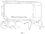
- FIG. 7 is a schematic view illustrating the structure of the assembly of the multifunctional cabin and the deck of the invention.
- FIG. 8 is a front isometric view of the chassis of the invention.
- FIG. 9 is a rear isometric view of the chassis of the invention.
- FIG. 10 is a schematic view illustrating the structure of the landing gear of the invention.
- FIG. 11 is a schematic view illustrating the structure of the docking fine-tuning mechanism
- FIG. 12 is a schematic view illustrating the structure of the connection of the Mecanum wheels and the fine-tuning drive motor.
- Embodiment 1 A house structure with expandable function, with reference to FIG. 1 , comprising a house body 20 , wherein an elevator shaft 21 is provided in the house body 20 , and a carrying elevator 22 is provided in the elevator shaft 21 ; a multifunctional balcony 23 is further provided on both sides of the elevator shaft 21 , and the multifunctional balcony 23 and the elevator shaft 21 are connected via a landing door 24 ; the car of the carrying elevator 22 is provided with a car front door, a car left door and a car right door, respectively; a multifunctional cabin 1 can be detachably connected to an automatic carrying system 35 capable of autonomous driving.
- a translation mechanism is provided at the bottom of the multifunctional cabin 1 , and the translation mechanism is used to translate the multifunctional cabin 1 into the elevator; after the multifunctional cabin 1 is carried to the designated position, the translation mechanism then translates the multifunctional cabin 1 onto the multifunctional balcony 23 .
- the structure of the translation mechanism is shown in FIG. 12 .
- Embodiment 2 A house structure with expandable function, with reference to FIG. 1 , comprising a house body 20 , wherein an elevator shaft 21 is provided in the house body 20 , and a carrying elevator 22 is provided in the elevator shaft 21 ; a multifunctional balcony 23 is further provided on both sides of the elevator shaft 21 , and the multifunctional balcony 23 and the elevator shaft 21 are connected via a landing door 24 ; the car of the carrying elevator 22 is provided with a car front door, a car left door and a car right door, respectively; a multifunctional cabin 1 can be detachably connected to an automatic carrying system 35 capable of autonomous driving.
- the multifunctional cabin 1 is carried into the carrying elevator 22 by the automatic carrying system 35 ;
- the car front door is opened, the multifunctional cabin 1 is carried into the carrying elevator 22 by the automatic carrying system 35 , and the car front door is closed;
- the carrying elevator 22 carries the multifunctional cabin 1 to the corresponding floor along the elevator shaft 21 , so that the car left/right door is aligned with the corresponding landing door 24 ;
- the landing door 24 and the car left/right door are opened at the same time, and the automatic carrying system 35 carries the multifunctional cabin 1 through the landing door 24 to the multifunctional balcony 23 ;
- the automatic carrying system 35 is separated from the multifunctional cabin 1 , and enters the carrying elevator 22 alone to leave the multifunctional balcony 23 ; at this time, the door of the multifunctional cabin 1 is just aligned with the balcony door 34 on the multifunctional balcony 23 , which is convenient for the owner to enter the multifunctional cabin 1 ;
- the automatic carrying system 35 comes to the multifunctional balcony 23 to carry the multifunctional cabin 1 away.
- An electrical plug 25 is provided on the wall of the multifunctional balcony 23 opposite to the landing door 24 , and the electrical plug 25 is detachably connected to the multifunctional cabin 1 .
- the detachably connected electrical plug 25 can be passed through a conventional male-female plug structure; through this structure, household electricity can be directly connected to the multifunctional cabin 1 to ensure continuous power supply.
- a pipe connector 26 can also be added on the wall surface as required to ensure that the multifunctional cabin 1 (such as a customized kitchen function cabin) of the corresponding function can be connected to household domestic water.
- the automatic carrying system 35 comprises a deck 2 ; the top of the deck 2 is detachably connected to the bottom of the multifunctional cabin 1 , and the bottom of the deck 2 is detachably connected to a chassis 3 capable of autonomous driving; a landing gear 4 is provided on both sides of one end of the deck 2 , a rear seat 5 is provided at the other end, and a rear wheel 6 is provided at the bottom of the rear seat 5 ; a vehicle pin 7 is provided at the bottom of the deck 2 ; a vehicle coupler 8 is provided on the rear end of the chassis 3 , and an attitude correction module 9 is further provided on the chassis 3 ; the chassis 3 can pass through the distance between the two landing gears 4 , and can be detachably connected to the deck 2 via coupling/decoupling of the vehicle coupler 8 and the vehicle pin 7 .
- the attitude correction module 9 continuously corrects the attitude of the chassis 3 according to the collected environmental signals around the deck 2 , so that the rear end of the chassis 3 is aligned between the two landing gears 4 and passes through, and the vehicle coupler 8 is coupled to the vehicle pin 7 to complete the docking, then the landing gears 4 are retracted to perform carrying; when the destination is reached, the landing gears 4 are pulled down, and the vehicle coupler 8 releases the vehicle pin 7 to complete the separation; after the separation, the chassis 3 can automatically drive away from the multifunctional balcony 23 .
- a joint positioning module is provided on the rear side of the rear seat 5 .
- the electrical plug 25 and/or the pipe connector 26 can be accurately docked through this module.
- the joint positioning module comprises:
- a positioning camera unit 27 for collecting position information of the electrical plug 25 and/or the pipe connector 26 on the wall;
- a positioning single line laser radar 28 for the docking positioning detection between the multifunctional cabin and the electrical plug 25 and/or the pipe connector 26 on the wall;
- a positioning millimeter wave radar 29 for measuring the distance between the multifunctional cabin and the electrical plug 25 and/or the pipe connector 26 on the wall.
- the system can fine-tune the positional relationship between the electrical plug 25 and/or the pipe connector 26 on the wall and the multifunctional cabin, and finally achieve the precise docking of the corresponding connector.
- a pair of reflecting plates III 30 is further provided on the wall of the multifunctional balcony 23 opposite to the landing door 24 , and the electrical plug 25 is located in the middle of the two reflecting plates III 30 .
- the reflecting plate III 30 can enhance the reflection of the positioning millimeter wave radar 29 , and is more conducive to positioning the corresponding joint of the millimeter wave radar 29 ; setting the corresponding joint in the middle enables the calculation of the position of the system to be easier and reduces the amount of calculation.
- a docking fine-tuning mechanism is provided at the bottom of the chassis 3 , and the docking fine-tuning mechanism comprises a lifting support mechanism 31 ; the lower four corners of the lifting support mechanism 31 are provided with Mecanum wheels 32 , and each Mecanum wheel 32 is driven by a fine-tuning drive motor 33 individually.
- This mechanism is set in consideration of facilitating the automatic carrying system 35 to enter/exit the carrying elevator 22 and facilitating the adjustment of the attitude of the multifunctional cabin 1 in the small space of the multifunctional balcony 23 to realize the docking with the electrical plug 25 and/or the pipe connector 26 ; when in use, the lifting support mechanism 31 is raised to make the Mecanum wheels 32 support the wheels of the chassis 3 off the ground; at this time, the speed of each trimming drive motor 33 is adjusted to drive the Mecanum wheels 32 to move at the same or different speeds to realize the movement or rotation of the front, rear, left and right of the chassis, thereby achieving the fine-tuning of the attitude of the multifunctional cabin 1 (applicable when the electric plug 25 and/or the pipe connector 26 are docked in the balcony) and the translation of the automatic carrier system 35 (applicable when entering and exiting the car front door).
- the attitude correction module 9 comprises:
- an inertial navigation unit 901 provided on the chassis 3 , which is used to provide attitude information; the inertial navigation unit 901 can complement the real-time satellite positioning system and laser radar data, and can provide additional data support in the Z-axis direction for the real-time satellite positioning system when there are scenes of non-planar and height differences;
- the side camera unit 902 is used to collect image data
- the side millimeter wave radar 903 is used to measure distance information of side obstacles
- the side millimeter wave radar 903 is a Doppler effect sensor, which is more sensitive to moving objects with speed, and at the same time is more sensitive to metal objects than non-metal objects
- the millimeter wave radar mainly outputs obstacle distance information
- the main function of the side camera unit 902 is to collect image data; by segmenting and processing the collected image data, and combining millimeter wave radar and laser radar to classify and predict obstacles, the obstacles that may exist in the lateral orientation are detected, and the distance of the obstacles from the vehicle body is calculated;
- a rear single line laser radar 904 and a rear millimeter wave radar 905 provided at the rear of the chassis 3 , wherein the rear single line laser radar 904 is used for the docking positioning detection between the multifunctional cabin and the chassis, and the rear millimeter wave radar 905 is used to measure distance information of obstacles in the rear; the rear single line laser radar 904 assists the close-range detection of obstacles with the principle of reflection of the emitted single line laser beam and the calculation of the relative distance through the reflection time;
- a reflecting plate I 10 is provided on the front side of the rear seat 5 ; a reflecting plate II 11 is provided on the front side of the landing gear 4 .
- the setting of the reflecting plate is to enhance the reflection of the radar wave to improve the accuracy of the position information, wherein the reflecting plate I 10 is to enhance the position accuracy of the coupling/decoupling of the vehicle coupler 8 and the vehicle pin 7 ; the reflecting plate II 11 is to enhance the position accuracy of the chassis 3 when passing through the distance between the two landing gears 4 and docking with the deck 2 .
- a lifting mechanism 12 is further provided at the front end of the chassis 3 , and the lifting mechanism 12 is provided with a front camera unit 13 , a real-time satellite positioning system 14 and a three-dimensional laser radar 15 .
- the lifting mechanism 12 lifts the front camera unit 13 , the real-time satellite positioning system 14 and the three-dimensional laser radar 15 to obtain a wider range of environmental signals and assists the chassis in autonomous driving.
- the autonomous driving system of the chassis 3 can adopt conventional unmanned driving systems such as Autoware, Baidu's Apollo or Google's unmanned driving system;
- the correction algorithm of the attitude correction module 9 can adopt the current conventional SLAM technology
- the landing gear 4 can adopt a landing gear structure as shown in FIG. 6 ; the structure thereof is: it comprises a horizontal support arm 16 , and the horizontal support arm 16 is hinged with a vertical support arm 17 ; an electric putter I 18 is connected between the horizontal support arm and the vertical support arm, and the vertical support arm 17 is driven to vertically expand and contract horizontally by the electric putter I 18 ; an electric putter II 19 is further provided in the vertical support arm 17 for supporting the ground.
- the vehicle pin 7 and the vehicle coupler 8 can adopt the vehicle pin and vehicle coupler of Holland Cruciform and SAF-Holland FW17, respectively;
- the inertial navigation unit 901 can adopt XSENS MTi-300;
- the positioning camera unit 27 and the side camera unit 902 adopt wide-angle cameras
- the positioning millimeter wave radar 29 , the side millimeter wave radar 903 , and the rear millimeter wave radar 905 can all adopt Continental SRR308, and the front millimeter wave radar 907 adopts Continental ARS408-21;
- the positioning single line laser radar 28 , the rear single line laser radar 904 , and the front single line laser radar 906 can all adopt HOKUYO UST-20LX;
- the reflecting plate I, the reflecting II, and the reflecting III can all adopt 3MTM Diamond GradeTM;
- the lifting mechanism can adopt conventional mechanical arms
- the front camera unit 13 can adopt FLIR Blackfly S BFS-PGE-16S2C;
- the real-time satellite positioning system 14 (RTK GNSS) can adopt the current conventional satellite positioning system;
- the three-dimensional laser radar 15 can adopt Velodyne VLP32.
Landscapes
- Engineering & Computer Science (AREA)
- Radar, Positioning & Navigation (AREA)
- Remote Sensing (AREA)
- Physics & Mathematics (AREA)
- Architecture (AREA)
- General Physics & Mathematics (AREA)
- Automation & Control Theory (AREA)
- Aviation & Aerospace Engineering (AREA)
- Civil Engineering (AREA)
- Structural Engineering (AREA)
- Electromagnetism (AREA)
- Computer Networks & Wireless Communication (AREA)
- Computer Vision & Pattern Recognition (AREA)
- Multimedia (AREA)
- Optics & Photonics (AREA)
- Residential Or Office Buildings (AREA)
- Control Of Position, Course, Altitude, Or Attitude Of Moving Bodies (AREA)
Abstract
Description
Claims (8)
Applications Claiming Priority (2)
| Application Number | Priority Date | Filing Date | Title |
|---|---|---|---|
| CN201911329461.2 | 2019-12-20 | ||
| CN201911329461.2A CN111021783A (en) | 2019-12-20 | 2019-12-20 | A functionally scalable housing structure |
Publications (2)
| Publication Number | Publication Date |
|---|---|
| US20210189749A1 US20210189749A1 (en) | 2021-06-24 |
| US11512486B2 true US11512486B2 (en) | 2022-11-29 |
Family
ID=70212423
Family Applications (1)
| Application Number | Title | Priority Date | Filing Date |
|---|---|---|---|
| US16/904,591 Active 2041-03-12 US11512486B2 (en) | 2019-12-20 | 2020-06-18 | House structure with expandable function |
Country Status (2)
| Country | Link |
|---|---|
| US (1) | US11512486B2 (en) |
| CN (1) | CN111021783A (en) |
Families Citing this family (3)
| Publication number | Priority date | Publication date | Assignee | Title |
|---|---|---|---|---|
| CN112158543A (en) * | 2020-09-03 | 2021-01-01 | 贵州翰凯斯智能技术有限公司 | Smart city life service system and use method |
| EP3968051B1 (en) * | 2020-09-15 | 2024-10-30 | Infineon Technologies AG | Guiding system for a robot, base station including such a guiding system, and method for guiding a robot |
| JP7076858B1 (en) * | 2021-07-29 | 2022-05-30 | 株式会社ランドビジネス | Dedicated elevator expansion renovation method |
Citations (9)
| Publication number | Priority date | Publication date | Assignee | Title |
|---|---|---|---|---|
| US5002449A (en) * | 1986-12-25 | 1991-03-26 | Kabushikikaisha Itoki Kosakusho | Automatic storage/retrieval apparatus for articles |
| US20170002579A1 (en) * | 2015-07-01 | 2017-01-05 | District Homes, LLC | Reconfigurable residential unit |
| US9630777B2 (en) * | 2011-09-28 | 2017-04-25 | Dematic Systems Gmbh | Multi-tier automated warehouse |
| US20180134492A1 (en) * | 2016-11-17 | 2018-05-17 | Alert Innovation Inc. | Automated-service retail system and method |
| US20190009985A1 (en) * | 2015-06-02 | 2019-01-10 | Alert Innovation Inc. | Storage and retrieval system |
| US20190100934A1 (en) * | 2012-02-17 | 2019-04-04 | Future Proof, LLC | Modular utilities unit structure |
| US20200040594A1 (en) * | 2018-08-03 | 2020-02-06 | Admares Group Oy | Building |
| US20200166267A1 (en) * | 2018-11-28 | 2020-05-28 | Dematic Corp. | Multiple temperature automated storage system and method |
| US20200362578A1 (en) * | 2017-11-13 | 2020-11-19 | Xinjiang Tiandi Group | House construction structure |
Family Cites Families (10)
| Publication number | Priority date | Publication date | Assignee | Title |
|---|---|---|---|---|
| JPH0726773A (en) * | 1993-07-12 | 1995-01-27 | Takenaka Komuten Co Ltd | Car elevator apparatus |
| JP2001146838A (en) * | 1999-11-19 | 2001-05-29 | Maeda Corp | Maintenance system for multistory building |
| JP2003193567A (en) * | 2002-10-16 | 2003-07-09 | Akito Yamamoto | Building |
| CN100366852C (en) * | 2005-02-04 | 2008-02-06 | 苏伟中 | Drawing and changing type integrated residence |
| CN102733645A (en) * | 2011-04-11 | 2012-10-17 | 李志民 | House with private garage |
| CN103276917A (en) * | 2013-05-21 | 2013-09-04 | 韩振洲 | Movable house system |
| CN204826206U (en) * | 2015-08-06 | 2015-12-02 | 蔡櫂隆 | Modular container house type building structure |
| CN109933076A (en) * | 2019-04-22 | 2019-06-25 | 贵州翰凯斯智能技术有限公司 | One kind being based on unpiloted mobile multifunctional vehicle system and application method |
| CN110053014A (en) * | 2019-05-07 | 2019-07-26 | 河北工业大学 | A kind of indoor intelligent mobile platform of view-based access control model SLAM |
| CN211736517U (en) * | 2019-12-20 | 2020-10-23 | 贵州翰凯斯智能技术有限公司 | Function extension formula building structure |
-
2019
- 2019-12-20 CN CN201911329461.2A patent/CN111021783A/en active Pending
-
2020
- 2020-06-18 US US16/904,591 patent/US11512486B2/en active Active
Patent Citations (10)
| Publication number | Priority date | Publication date | Assignee | Title |
|---|---|---|---|---|
| US5002449A (en) * | 1986-12-25 | 1991-03-26 | Kabushikikaisha Itoki Kosakusho | Automatic storage/retrieval apparatus for articles |
| US9630777B2 (en) * | 2011-09-28 | 2017-04-25 | Dematic Systems Gmbh | Multi-tier automated warehouse |
| US20190100934A1 (en) * | 2012-02-17 | 2019-04-04 | Future Proof, LLC | Modular utilities unit structure |
| US20190009985A1 (en) * | 2015-06-02 | 2019-01-10 | Alert Innovation Inc. | Storage and retrieval system |
| US20170002579A1 (en) * | 2015-07-01 | 2017-01-05 | District Homes, LLC | Reconfigurable residential unit |
| US20180134492A1 (en) * | 2016-11-17 | 2018-05-17 | Alert Innovation Inc. | Automated-service retail system and method |
| US20200362578A1 (en) * | 2017-11-13 | 2020-11-19 | Xinjiang Tiandi Group | House construction structure |
| US20200040594A1 (en) * | 2018-08-03 | 2020-02-06 | Admares Group Oy | Building |
| US20200166267A1 (en) * | 2018-11-28 | 2020-05-28 | Dematic Corp. | Multiple temperature automated storage system and method |
| US11067329B2 (en) * | 2018-11-28 | 2021-07-20 | Dematic Corp. | Multiple temperature automated storage system and method |
Also Published As
| Publication number | Publication date |
|---|---|
| US20210189749A1 (en) | 2021-06-24 |
| CN111021783A (en) | 2020-04-17 |
Similar Documents
| Publication | Publication Date | Title |
|---|---|---|
| US11512486B2 (en) | House structure with expandable function | |
| CN110262546B (en) | A kind of tunnel intelligent drone inspection method | |
| CN113085896B (en) | A system and method for assisted automatic driving of a modern rail cleaning vehicle | |
| CN104881027B (en) | Wheel-track combined Intelligent Mobile Robot active obstacle system and control method | |
| CN109631896A (en) | A kind of parking lot autonomous parking localization method based on vehicle vision and motion information | |
| AU2018335390A1 (en) | Detecting motion of an autonomous vehicle using radar technology | |
| CN109434795A (en) | A kind of loading stair climbing robot with target following and automatic obstacle-avoiding | |
| CN212781778U (en) | Intelligent vehicle based on vision SLAM | |
| KR20140039243A (en) | Sensor field selection | |
| CN211943155U (en) | A multi-sensor fusion intelligent integrated vehicle | |
| CN207397090U (en) | A kind of unmanned distribution trolley | |
| CN210706760U (en) | A ground-air cooperative communication exploration device based on inertial navigation | |
| Yamauchi | Autonomous urban reconnaissance using man-portable UGVs | |
| CN108705977B (en) | An internet driverless car | |
| CN107643756A (en) | A kind of unmanned distribution trolley and its mode of progression | |
| CN211736517U (en) | Function extension formula building structure | |
| CN113759787A (en) | Unmanned robot for closed park and working method | |
| CN211906081U (en) | Unmanned small-sized sweeping machine control system based on path tracking | |
| CN108858226B (en) | Intelligent tableware recycling robot with multi-sensor integrated SLAM technology | |
| US12447906B2 (en) | Sensor case, sensor system and vehicle | |
| CN213069232U (en) | Seamless positioning navigation unmanned vehicle for synchronous weather guarantee | |
| CN115290069B (en) | Multi-source heterogeneous sensor data fusion and collaborative perception handheld mobile platform | |
| CN210760409U (en) | A detachable car body structure based on unmanned driving | |
| CN215042718U (en) | Self-driving vehicles with multiple sensing devices | |
| CN106926777A (en) | With the device of automatic range on a kind of car |
Legal Events
| Date | Code | Title | Description |
|---|---|---|---|
| FEPP | Fee payment procedure |
Free format text: ENTITY STATUS SET TO UNDISCOUNTED (ORIGINAL EVENT CODE: BIG.); ENTITY STATUS OF PATENT OWNER: SMALL ENTITY |
|
| FEPP | Fee payment procedure |
Free format text: ENTITY STATUS SET TO SMALL (ORIGINAL EVENT CODE: SMAL); ENTITY STATUS OF PATENT OWNER: SMALL ENTITY |
|
| STPP | Information on status: patent application and granting procedure in general |
Free format text: DOCKETED NEW CASE - READY FOR EXAMINATION |
|
| AS | Assignment |
Owner name: GUIZHOU HANKAISI INTELLIGENT TECHNOLOGY CO., LTD., CHINA Free format text: ASSIGNMENT OF ASSIGNORS INTEREST;ASSIGNORS:YU, CHUAN;ZHANG, MING;ZENG, DECHONG;AND OTHERS;REEL/FRAME:054510/0338 Effective date: 20201201 |
|
| STPP | Information on status: patent application and granting procedure in general |
Free format text: NON FINAL ACTION MAILED |
|
| STPP | Information on status: patent application and granting procedure in general |
Free format text: RESPONSE TO NON-FINAL OFFICE ACTION ENTERED AND FORWARDED TO EXAMINER |
|
| STPP | Information on status: patent application and granting procedure in general |
Free format text: NOTICE OF ALLOWANCE MAILED -- APPLICATION RECEIVED IN OFFICE OF PUBLICATIONS |
|
| STPP | Information on status: patent application and granting procedure in general |
Free format text: AWAITING TC RESP., ISSUE FEE NOT PAID |
|
| STPP | Information on status: patent application and granting procedure in general |
Free format text: AWAITING TC RESP., ISSUE FEE NOT PAID |
|
| STPP | Information on status: patent application and granting procedure in general |
Free format text: NOTICE OF ALLOWANCE MAILED -- APPLICATION RECEIVED IN OFFICE OF PUBLICATIONS |
|
| AS | Assignment |
Owner name: GUIZHOU HANKAISI INTELLIGENT TECHNOLOGY CO., LTD., CHINA Free format text: ASSIGNMENT OF ASSIGNORS INTEREST;ASSIGNORS:YU, CHUAN;ZHANG, MING;ZENG, DECHONG;AND OTHERS;REEL/FRAME:061403/0481 Effective date: 20221013 |
|
| STPP | Information on status: patent application and granting procedure in general |
Free format text: PUBLICATIONS -- ISSUE FEE PAYMENT VERIFIED |
|
| STCF | Information on status: patent grant |
Free format text: PATENTED CASE |