US11510558B2 - Endoscope observation method and endoscope apparatus - Google Patents
Endoscope observation method and endoscope apparatus Download PDFInfo
- Publication number
- US11510558B2 US11510558B2 US16/047,074 US201816047074A US11510558B2 US 11510558 B2 US11510558 B2 US 11510558B2 US 201816047074 A US201816047074 A US 201816047074A US 11510558 B2 US11510558 B2 US 11510558B2
- Authority
- US
- United States
- Prior art keywords
- narrowband light
- characteristic substance
- characteristic
- substance
- image
- Prior art date
- Legal status (The legal status is an assumption and is not a legal conclusion. Google has not performed a legal analysis and makes no representation as to the accuracy of the status listed.)
- Active, expires
Links
- 238000000034 method Methods 0.000 title claims abstract description 38
- 239000000126 substance Substances 0.000 claims abstract description 447
- 238000002835 absorbance Methods 0.000 claims abstract description 120
- 238000003384 imaging method Methods 0.000 claims abstract description 43
- 230000001678 irradiating effect Effects 0.000 claims abstract description 21
- 239000000975 dye Substances 0.000 claims description 8
- 230000008859 change Effects 0.000 claims description 3
- 230000002194 synthesizing effect Effects 0.000 claims description 2
- 238000000862 absorption spectrum Methods 0.000 description 27
- 230000003287 optical effect Effects 0.000 description 20
- 230000015572 biosynthetic process Effects 0.000 description 17
- 206010028980 Neoplasm Diseases 0.000 description 16
- 230000003902 lesion Effects 0.000 description 16
- 108010054147 Hemoglobins Proteins 0.000 description 14
- 102000001554 Hemoglobins Human genes 0.000 description 14
- 238000003780 insertion Methods 0.000 description 14
- 230000037431 insertion Effects 0.000 description 14
- KHLVKKOJDHCJMG-QDBORUFSSA-L indigo carmine Chemical compound [Na+].[Na+].N/1C2=CC=C(S([O-])(=O)=O)C=C2C(=O)C\1=C1/NC2=CC=C(S(=O)(=O)[O-])C=C2C1=O KHLVKKOJDHCJMG-QDBORUFSSA-L 0.000 description 13
- 229960003988 indigo carmine Drugs 0.000 description 13
- 235000012738 indigotine Nutrition 0.000 description 13
- 239000004179 indigotine Substances 0.000 description 13
- 238000001514 detection method Methods 0.000 description 12
- 238000003786 synthesis reaction Methods 0.000 description 12
- 239000013307 optical fiber Substances 0.000 description 11
- 210000004204 blood vessel Anatomy 0.000 description 6
- 230000008569 process Effects 0.000 description 6
- 238000012545 processing Methods 0.000 description 6
- 238000005286 illumination Methods 0.000 description 5
- RBTBFTRPCNLSDE-UHFFFAOYSA-N 3,7-bis(dimethylamino)phenothiazin-5-ium Chemical compound C1=CC(N(C)C)=CC2=[S+]C3=CC(N(C)C)=CC=C3N=C21 RBTBFTRPCNLSDE-UHFFFAOYSA-N 0.000 description 4
- 238000000605 extraction Methods 0.000 description 4
- 229960000907 methylthioninium chloride Drugs 0.000 description 4
- 238000010187 selection method Methods 0.000 description 4
- 201000011510 cancer Diseases 0.000 description 3
- 238000010586 diagram Methods 0.000 description 3
- 230000006870 function Effects 0.000 description 3
- 238000012986 modification Methods 0.000 description 3
- 230000004048 modification Effects 0.000 description 3
- 239000000306 component Substances 0.000 description 2
- 230000007423 decrease Effects 0.000 description 2
- 230000000694 effects Effects 0.000 description 2
- 239000000284 extract Substances 0.000 description 2
- 230000006872 improvement Effects 0.000 description 2
- 229960004657 indocyanine green Drugs 0.000 description 2
- MOFVSTNWEDAEEK-UHFFFAOYSA-M indocyanine green Chemical compound [Na+].[O-]S(=O)(=O)CCCCN1C2=CC=C3C=CC=CC3=C2C(C)(C)C1=CC=CC=CC=CC1=[N+](CCCCS([O-])(=O)=O)C2=CC=C(C=CC=C3)C3=C2C1(C)C MOFVSTNWEDAEEK-UHFFFAOYSA-M 0.000 description 2
- 230000002265 prevention Effects 0.000 description 2
- 230000035945 sensitivity Effects 0.000 description 2
- 206010058467 Lung neoplasm malignant Diseases 0.000 description 1
- 239000008280 blood Substances 0.000 description 1
- 210000004369 blood Anatomy 0.000 description 1
- 239000012503 blood component Substances 0.000 description 1
- 238000007796 conventional method Methods 0.000 description 1
- 230000008878 coupling Effects 0.000 description 1
- 238000010168 coupling process Methods 0.000 description 1
- 238000005859 coupling reaction Methods 0.000 description 1
- 238000013500 data storage Methods 0.000 description 1
- 230000003247 decreasing effect Effects 0.000 description 1
- 201000010099 disease Diseases 0.000 description 1
- 208000037265 diseases, disorders, signs and symptoms Diseases 0.000 description 1
- 238000002795 fluorescence method Methods 0.000 description 1
- 108010036302 hemoglobin AS Proteins 0.000 description 1
- 206010073071 hepatocellular carcinoma Diseases 0.000 description 1
- 231100000844 hepatocellular carcinoma Toxicity 0.000 description 1
- 238000007689 inspection Methods 0.000 description 1
- 210000002429 large intestine Anatomy 0.000 description 1
- 239000004973 liquid crystal related substance Substances 0.000 description 1
- 210000005228 liver tissue Anatomy 0.000 description 1
- 201000005202 lung cancer Diseases 0.000 description 1
- 208000020816 lung neoplasm Diseases 0.000 description 1
- 230000007246 mechanism Effects 0.000 description 1
- 238000012216 screening Methods 0.000 description 1
- 210000001519 tissue Anatomy 0.000 description 1
- 210000002438 upper gastrointestinal tract Anatomy 0.000 description 1
Images


Classifications
-
- A—HUMAN NECESSITIES
- A61—MEDICAL OR VETERINARY SCIENCE; HYGIENE
- A61B—DIAGNOSIS; SURGERY; IDENTIFICATION
- A61B1/00—Instruments for performing medical examinations of the interior of cavities or tubes of the body by visual or photographical inspection, e.g. endoscopes; Illuminating arrangements therefor
- A61B1/06—Instruments for performing medical examinations of the interior of cavities or tubes of the body by visual or photographical inspection, e.g. endoscopes; Illuminating arrangements therefor with illuminating arrangements
- A61B1/0638—Instruments for performing medical examinations of the interior of cavities or tubes of the body by visual or photographical inspection, e.g. endoscopes; Illuminating arrangements therefor with illuminating arrangements providing two or more wavelengths
-
- A—HUMAN NECESSITIES
- A61—MEDICAL OR VETERINARY SCIENCE; HYGIENE
- A61B—DIAGNOSIS; SURGERY; IDENTIFICATION
- A61B1/00—Instruments for performing medical examinations of the interior of cavities or tubes of the body by visual or photographical inspection, e.g. endoscopes; Illuminating arrangements therefor
- A61B1/00002—Operational features of endoscopes
- A61B1/00004—Operational features of endoscopes characterised by electronic signal processing
- A61B1/00009—Operational features of endoscopes characterised by electronic signal processing of image signals during a use of endoscope
- A61B1/000094—Operational features of endoscopes characterised by electronic signal processing of image signals during a use of endoscope extracting biological structures
-
- A—HUMAN NECESSITIES
- A61—MEDICAL OR VETERINARY SCIENCE; HYGIENE
- A61B—DIAGNOSIS; SURGERY; IDENTIFICATION
- A61B5/00—Measuring for diagnostic purposes; Identification of persons
- A61B5/0059—Measuring for diagnostic purposes; Identification of persons using light, e.g. diagnosis by transillumination, diascopy, fluorescence
- A61B5/0075—Measuring for diagnostic purposes; Identification of persons using light, e.g. diagnosis by transillumination, diascopy, fluorescence by spectroscopy, i.e. measuring spectra, e.g. Raman spectroscopy, infrared absorption spectroscopy
-
- A—HUMAN NECESSITIES
- A61—MEDICAL OR VETERINARY SCIENCE; HYGIENE
- A61B—DIAGNOSIS; SURGERY; IDENTIFICATION
- A61B5/00—Measuring for diagnostic purposes; Identification of persons
- A61B5/0059—Measuring for diagnostic purposes; Identification of persons using light, e.g. diagnosis by transillumination, diascopy, fluorescence
- A61B5/0082—Measuring for diagnostic purposes; Identification of persons using light, e.g. diagnosis by transillumination, diascopy, fluorescence adapted for particular medical purposes
- A61B5/0084—Measuring for diagnostic purposes; Identification of persons using light, e.g. diagnosis by transillumination, diascopy, fluorescence adapted for particular medical purposes for introduction into the body, e.g. by catheters
-
- G—PHYSICS
- G02—OPTICS
- G02B—OPTICAL ELEMENTS, SYSTEMS OR APPARATUS
- G02B23/00—Telescopes, e.g. binoculars; Periscopes; Instruments for viewing the inside of hollow bodies; Viewfinders; Optical aiming or sighting devices
- G02B23/24—Instruments or systems for viewing the inside of hollow bodies, e.g. fibrescopes
- G02B23/2407—Optical details
- G02B23/2461—Illumination
-
- A—HUMAN NECESSITIES
- A61—MEDICAL OR VETERINARY SCIENCE; HYGIENE
- A61B—DIAGNOSIS; SURGERY; IDENTIFICATION
- A61B1/00—Instruments for performing medical examinations of the interior of cavities or tubes of the body by visual or photographical inspection, e.g. endoscopes; Illuminating arrangements therefor
- A61B1/00163—Optical arrangements
- A61B1/00186—Optical arrangements with imaging filters
-
- A—HUMAN NECESSITIES
- A61—MEDICAL OR VETERINARY SCIENCE; HYGIENE
- A61B—DIAGNOSIS; SURGERY; IDENTIFICATION
- A61B1/00—Instruments for performing medical examinations of the interior of cavities or tubes of the body by visual or photographical inspection, e.g. endoscopes; Illuminating arrangements therefor
- A61B1/04—Instruments for performing medical examinations of the interior of cavities or tubes of the body by visual or photographical inspection, e.g. endoscopes; Illuminating arrangements therefor combined with photographic or television appliances
- A61B1/045—Control thereof
-
- A—HUMAN NECESSITIES
- A61—MEDICAL OR VETERINARY SCIENCE; HYGIENE
- A61B—DIAGNOSIS; SURGERY; IDENTIFICATION
- A61B1/00—Instruments for performing medical examinations of the interior of cavities or tubes of the body by visual or photographical inspection, e.g. endoscopes; Illuminating arrangements therefor
- A61B1/04—Instruments for performing medical examinations of the interior of cavities or tubes of the body by visual or photographical inspection, e.g. endoscopes; Illuminating arrangements therefor combined with photographic or television appliances
- A61B1/05—Instruments for performing medical examinations of the interior of cavities or tubes of the body by visual or photographical inspection, e.g. endoscopes; Illuminating arrangements therefor combined with photographic or television appliances characterised by the image sensor, e.g. camera, being in the distal end portion
-
- A—HUMAN NECESSITIES
- A61—MEDICAL OR VETERINARY SCIENCE; HYGIENE
- A61B—DIAGNOSIS; SURGERY; IDENTIFICATION
- A61B1/00—Instruments for performing medical examinations of the interior of cavities or tubes of the body by visual or photographical inspection, e.g. endoscopes; Illuminating arrangements therefor
- A61B1/06—Instruments for performing medical examinations of the interior of cavities or tubes of the body by visual or photographical inspection, e.g. endoscopes; Illuminating arrangements therefor with illuminating arrangements
- A61B1/0661—Endoscope light sources
- A61B1/0684—Endoscope light sources using light emitting diodes [LED]
Definitions
- the present invention relates to an endoscope observation method to observe a subject, and an endoscope apparatus.
- finding of a noticeable region in a subject e.g., a lesion in a body cavity by an endoscope has been performed as follows. That is, a rough observation is firstly performed by screening with white light. On the basis of results of the observation, specific light such as NBI is irradiated to an area where a disease is suspected, to detect a characteristic substance closely related to the lesion, e.g., hemoglobin or the like in the blood, as disclosed in Jpn. Pat. Appln. KOKAI Publication No. 2015-91467. The thus obtained detection results of the characteristic substance are useful for the finding of the lesion of cancer, tumor or the like.
- a characteristic substance closely related to the lesion e.g., hemoglobin or the like in the blood
- An endoscope observation method includes irradiating, to an observation object, first narrowband light and second narrowband light having wavelengths at which absorbances of a first characteristic substance and a second characteristic substance related to a predetermined state of the observation object and contained in the observation object are mutually different, performing imaging by use of reflected light of the first narrowband light from the observation object to obtain first image data, and by use of reflected light of the second narrowband light to obtain second image data, and forming a characteristic substance presence image regarding presence of the first characteristic substance and the second characteristic substance, on the basis of a characteristic amount of the first characteristic substance contained in the first image data and a characteristic amount of the second characteristic substance contained in the second image data.
- FIG. 1A is a flowchart to explain the outline of an endoscope observation method according to an embodiment of the present invention
- FIG. 2 is a flowchart to explain the detail of an endoscope observation method according to an embodiment of the present invention
- FIG. 3 is a view to explain a difference between absorbances of two characteristic substances
- FIG. 4 is a view showing absorption spectra of a first characteristic substance and a second characteristic substance to explain an example of a selection method of first narrowband light and second narrowband light;
- FIG. 5 is a view showing absorption spectra of a first characteristic substance and a second characteristic substance to explain another example of the selection method of the first narrowband light and the second narrowband light;
- FIG. 6 is a view showing absorption spectra of the first characteristic substance and the second characteristic substance to explain still another example of the selection method of the first narrowband light and the second narrowband light;
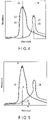
- FIG. 7 is a view showing an absorption spectrum of hemoglobin as an example of the first characteristic substance
- FIG. 8 is a view showing an absorption spectrum of indocyanine green as an example of the second characteristic substance
- FIG. 9 is a view showing an absorption spectrum of indigo carmine as another example of the first characteristic substance.
- FIG. 10 is a view showing a first luminance image and a second luminance image
- FIG. 11 is a view to explain the formation of a synthetic luminance image of the first luminance image and the second luminance image;
- FIG. 12 is a view to explain an overlapping region of the first characteristic substance and the second characteristic substance
- FIG. 13A is a view showing the first luminance image and the second luminance image in a case where the first characteristic substance is only detected;
- FIG. 13B is a view showing the second luminance image after contrast increase processing that is obtained by increasing contrast for a region of the second luminance image corresponding to a region where the first characteristic substance is detected in the first luminance image of FIG. 13A ;
- FIG. 14 is a view showing a characteristic substance emphasizing image
- FIG. 15 is a view showing an absorption spectrum of methylene blue as still another example of the first characteristic substance
- FIG. 16 is an external view of an endoscope apparatus to perform an endoscope observation method according to an embodiment of the present invention.
- FIG. 17 is a block diagram showing an example of a schematic constitution of the endoscope apparatus.
- FIG. 18 is a block diagram showing another example of the schematic constitution of the endoscope apparatus.
- an endoscope referred to in this specification should not be limited to an endoscope for medical use (an upper gastrointestinal tract endoscope, a large intestine endoscope, an ultrasonic endoscope, a cystoscope, a pyeloscope, a bronchoscope, or the like) and an endoscope for industrial use, and the endoscope indicates a general instrument having an insertion section to be inserted into a subject (e.g., a body cavity (a lumen)).
- narrowband light is first selected (Step S 1 ).
- a subject 10 that is an intended observation object might contain a noticeable region 12 , e.g., a lesion in a body cavity, and such a noticeable region 12 contains a first characteristic substance 14 and a second characteristic substance 16 .
- first narrowband light contained in a first wavelength range and second narrowband light contained in a second wavelength range are selected, the first narrowband light and second narrowband light having wavelengths at which absorbances of the first characteristic substance 14 and the second characteristic substance 16 are mutually different. It is to be noted that the selection method of the first and second narrowband light will be described in detail hereinafter.
- the thus selected first narrowband light and second narrowband light are irradiated from an irradiating section arranged at a distal end of the insertion section of the endoscope to the subject 10 (Step S 2 ). Then, in an imaging section similarly arranged at the distal end of the insertion section of the endoscope, imaging is performed by use of reflected light of the first narrowband light and reflected light of the second narrowband light from the subject 10 (Step S 3 ).
- Step S 4 On the basis of image data obtained by the imaging, a characteristic substance presence image that indicates the presence of the first characteristic substance and the second characteristic substance is formed (Step S 4 ). Then, the thus formed characteristic substance presence image is displayed on a display such as a monitor connected to a main section (a video processor) with which the endoscope is connected (Step S 5 ).
- the narrowband light are irradiated to the subject 10 , for the characteristic substances 14 , 16 closely related to the noticeable region 12 that is the intended observation object, the narrowband light having the wavelengths at which the absorbances of the respective characteristic substances are mutually different, so that the characteristic substances 14 , 16 related to the noticeable region 12 can be detected. That is, the observation object has been heretofore discovered from detection results of a single characteristic substance, but in the present embodiment, the observation object is discovered from detection results of the characteristic substances, and hence it is possible to improve discovery precision of the observation object.
- the first characteristic substance 14 and the second characteristic substance 16 are different kinds of dyes suitable for different use applications.
- the first characteristic substance 14 is hemoglobin, which is a blood vessel emphasizing substance to emphasize blood vessels
- the second characteristic substance 16 is indigo carmine, which is a structure emphasizing substance to emphasize a structure or a bit pattern of cells.
- the first characteristic substance 14 and the second characteristic substance 16 are suitably dyes that are known as markers for cancers.
- the employment of various kinds of markers for the cancers exhibits effects to heighten a detection sensitivity and the prevention of cancer detection errors.
- Step S 1 to select the two kinds of narrowband light includes a characteristic substance selecting step (Step S 11 ), a narrowband light wavelength selecting step (Step S 12 ), and an irradiation sequence selecting step (Step S 13 ).
- the characteristic substance selecting step of Step S 11 is a step to select the first characteristic substance 14 and the second characteristic substance 16 .
- the selection of the first and second characteristic substances 14 and 16 can be performed, for example, by optional selection of an observer from a list of characteristic substances.
- the list of the characteristic substances for example, a combination of the two characteristic substances related to a tumor or a lesion such as a combination of hemoglobin, which is a dye to emphasize a structure of a blood vessel component closely related to the tumor, and indocyanine green (hereinafter abbreviated as ICG), which is a dye to emphasize a structure of a bit pattern or the like are previously listed up.
- ICG indocyanine green
- a combination of characteristic substances may be selected in accordance with a kind of the noticeable region 12 .
- a list of recommended combinations in accordance with a kind of the noticeable region 12 may be previously prepared, and the first and second characteristic substances 14 , 16 may be selected from the list.
- the “selection” in each of the characteristic substance selecting step, the narrowband light wavelength selecting step and the irradiation sequence selecting step of the above steps S 11 to S 13 indicates the “selection” in a broad sense. That is, the “selection” covers a case of selecting among plural choices, and a case of a previously determined choice owing to no choice.
- a desired characteristic substance is selected from a list of recommended combinations corresponding to the specified kind of the noticeable region 12 .
- the narrowband light wavelength selecting step of Step S 12 is a step to select the first narrowband light and the second narrowband light in accordance with the selected first and second characteristic substances 14 , 16 .
- the two kinds of narrowband light (the first narrowband light and the second narrowband light) having mutually different wavelengths that can detect the two mutually different characteristic substances (the first characteristic substance 14 and the second characteristic substance 16 ) are selected in the following manner.
- the first narrowband light and the second narrowband light are selected so that a difference between absorbances of the first characteristic substance 14 and the second characteristic substance 16 at the respective wavelengths is a predetermined value or more.
- the first narrowband light containing a wavelength at which a difference between the absorbances of the first characteristic substance 14 and the second characteristic substance 16 at the respective wavelengths is a largest value or a maximum value
- the second narrowband light containing a wavelength at which the difference is a smallest value or a minimum value are selected as the first narrowband light and the second narrowband light.
- the difference between the absorbances is a value obtained by subtracting the absorbance of the second characteristic substance 16 from that of the first characteristic substance 14 . Therefore, as understood from an optical absorption spectrum 18 of the first characteristic substance and an optical absorption spectrum 20 of the second characteristic substance shown in FIG. 3 , when the absorbances are reversed, a largest value 22 or a maximum value is a positive value, but a smallest value 26 or a minimum value is a negative value.
- a wavelength to be selected is not a wavelength at which the above difference is the smallest value 26 or the minimum value, but it is desirable to select a peak wavelength (not in the same wavelength range) separated from a wavelength at which the above difference is the largest value 22 or the maximum value.
- one characteristic substance is not specified, but specifying the two characteristic substances 14 , 16 is desired. Therefore, when peak wavelengths of the respective characteristic substances are simply selected, it is difficult to specify the characteristic substances, in a case where the peak wavelengths exist at near positions (in the same wavelength range).
- a difference between the absorbances is first calculated at every wavelength.
- the difference between the absorbances is a value obtained by subtracting an absorbance of the second characteristic substance 16 from that of the first characteristic substance 14 .
- a largest value and a smallest value of the calculated difference between the absorbances are obtained, and narrowband light having a wavelength corresponding to the largest value is selected as the first narrowband light and narrowband light having a wavelength corresponding to the smallest value is selected as the second narrowband light.
- the smallest value is negative.
- narrowband light having the wavelength that takes the largest value 22 of the difference between the absorbances is selected as first narrowband light 24
- narrowband light having the wavelength that takes the smallest value 26 (the negative value) of the difference between the absorbances is selected as second narrowband light 28 .
- each of the two characteristic substances 14 and 16 can be specified by selecting the wavelength in which the difference between the absorbances is largest or maximum, or smallest or minimum.
- each absorbance of the characteristic substances when a peak or a bottom of each absorbance of the characteristic substances is noticeable, it is easier to specify the characteristic substance by using the peak or the bottom. Accordingly, in fact, even in a case where the difference between the absorbances is not largest nor maximum or smallest nor minimum, if the difference between the absorbances is large at the peak wavelength and in the vicinity of the peak wavelength of the absorbance of the first characteristic substance 14 (the second characteristic substance 16 ), this wavelength may be preferentially selected. In this case, the difference between the absorbances is suitably half or more of the largest value.
- each of the first narrowband light 24 and the second narrowband light 28 can be selected.
- narrowband light contained in a third wavelength range containing a wavelength at which an absorbance at every wavelength of each of the first characteristic substance 14 and the second characteristic substance 16 is a largest value or a maximum value narrowband light contained in a fourth wavelength range containing a wavelength at which an absorbance at every wavelength of each of the characteristic substances is a smallest value or a minimum value are selected.
- the selection of the first narrowband light 24 and the second narrowband light 28 it is possible to use a ratio of absorbances instead of the difference between an absorbance at every wavelength of the first characteristic substance 14 and an absorbance at every wavelength of the second characteristic substance 16 .
- narrowband light having a wavelength at which an absorbance of one characteristic substance is 1 ⁇ 2 or less, suitably 1 ⁇ 5 or less and further suitably 1/10 or less of that of the other characteristic substance, and narrowband light having a wavelength at which an absorbance of the other characteristic substance is 1 ⁇ 2 or less, suitably 1 ⁇ 5 or less and further suitably 1/10 or less of that of the one characteristic substance, as the first narrowband light and the second narrowband light may be selected as the first narrowband light 24 and the second narrowband light 28 , respectively.
- the first narrowband light 24 narrowband light having a wavelength at which an absorbance A of the first characteristic substance 14 and an absorbance B of the second characteristic substance 16 have a relation of B/A ⁇ 1 ⁇ 2, suitably B/A ⁇ 1 ⁇ 5 and further suitably B/A ⁇ 1/10 is selected.
- the second narrowband light 28 although not shown in FIG. 5 , the narrowband light having a wavelength at which A/B ⁇ 1 ⁇ 2, suitably A/B ⁇ 1 ⁇ 5 and further suitably A/B ⁇ 1/10 is selected.
- the light having the wavelength at which the absorbance is extremely different is selected, so that the two characteristic substances 14 , 16 can be specified, but when the absorbance is 1/10 or less, the characteristic substances can be separated with further higher precision.
- the narrowband light may be selected from each of ranges where the absorbances of the first characteristic substance 14 and the second characteristic substance 16 are reversed. That is, in the first characteristic substance 14 and the second characteristic substance 16 , two kinds of narrowband light having wavelengths at which absorbances are mutually reversed are selected as the first narrowband light 24 and the second narrowband light 28 .
- the first narrowband light 24 is selected in a wavelength range where the absorbance of the optical absorption spectrum 18 of the first characteristic substance is high and the absorbance of the optical absorption spectrum 20 of the second characteristic substance is low
- the second narrowband light 28 is selected in a wavelength range where the absorbance of the optical absorption spectrum 18 of the first characteristic substance is low and the absorbance of the optical absorption spectrum 20 of the second characteristic substance is high.
- the two kinds of light having the wavelengths at which the absorbances are reversed are selected, so that the two characteristic substances can be specified.
- the above-mentioned selection of the first and second narrowband light 24 , 28 can automatically be determined in accordance with the selection of the first and second characteristic substances 14 , 16 .
- the optical absorption spectrum 18 of the first characteristic substance and the optical absorption spectrum 20 of the second characteristic substance are presented to the observer in accordance with the selection of the first characteristic substance 14 and the second characteristic substance 16 .
- intended wavelengths may be designated as the first narrowband light 24 and the second narrowband light 28 on the basis of the two absorption spectra.
- the choices of the first and second narrowband light 24 and 28 may be presented by using previously stored information on a type of light source mounted in the endoscope.
- the type of light source mounted in the endoscope and including the wavelength range where the ratio of or the difference between the optical absorption spectrum 18 of the first characteristic substance and the optical absorption spectrum 20 of the second characteristic substance is a predetermined value or more may automatically be selected or may be presented to and selected by the observer.
- the first narrowband light 24 and the second narrowband light 28 are selected.
- a method of simultaneously detecting two kinds of characteristic substances closely related to the tumor by use of two kinds of narrowband light further contributes to the improvement of the discovery precision of the noticeable region 12 (the lesion or the like) of the subject 10 that is the intended observation object.
- the hemoglobin is a blood component, and hence detection thereof is effective in predicting a position of a blood vessel closely related to the tumor. Furthermore, ICG is effective in identifying a lung cancer by use of a fluorescence method and by utilization of a phenomenon of congestion in a noncancerous liver tissue excluded from a hepatocellular carcinoma tissue or tumor.
- the two kinds of narrowband light 24 and 28 with which such two characteristic substances can be detected are selected in the following manner.
- Hemoglobin which is the first characteristic substance 14 , has a peak of absorbance in the vicinity of a range of 400 nm to 420 nm and its absorbance is in excess of 1000 at 400 nm as shown in FIG. 7 .
- the absorbance of ICG which is the second characteristic substance 16 , is sufficiently small in the vicinity of 400 nm as shown in FIG. 8 . Therefore, a difference between the absorbances in this case is a maximum value, and narrowband light having a wavelength in the vicinity of 400 nm is selected as the first narrowband light 24 .
- ICG which is the second characteristic substance 16
- ICG has a peak (approximately 750) of the absorbance in the vicinity of 790 nm.
- the absorbance of hemoglobin which is the first characteristic substance 14
- the absorbance of hemoglobin is sufficiently small and nearly at its bottom in 790 nm. Consequently, a difference between the absorbances in this case is a smallest value, and narrowband light having a wavelength in the vicinity of 790 nm is selected as the second narrowband light 28 .
- Indigo carmine is used in a contrast method of applying a phenomenon where a dye solution accumulates into a dented surface to emphasize surface unevenness in dye endoscope inspection, and is useful for recognition of a lesion.
- indigo carmine has a peak of absorbance at approximately 30 in the vicinity of 610 nm.
- the absorbance of ICG which is the second characteristic substance 16
- the absorbance of ICG is from approximately 0 to 5 in the vicinity of 610 nm. Therefore, a difference between the absorbances in this case is a maximum value, and narrowband light having a wavelength in the vicinity of 610 nm is selected as the first narrowband light 24 .
- ICG which is the second characteristic substance 16
- ICG has a peak (approximately 750) of absorbance in the vicinity of 790 nm.
- the absorbance of indigo carmine which is the first characteristic substance 14
- the absorbance of indigo carmine is sufficiently small and nearly at its bottom in the vicinity of 790 nm. Therefore, a difference between the absorbances in this case is a minimum value, and narrowband light having a wavelength in the vicinity of 790 nm is selected as the second narrowband light 28 .
- the method of finding the noticeable region 12 in an intended observation region
- two examples have specifically been described where two kinds of characteristic substances and two kinds of narrowband light 24 and 28 are selected.
- the two characteristic substances can simultaneously be detected, and hence the example is useful for the improvement of the discovery precision of the noticeable region 12 (the tumor or the like).
- the irradiation sequence selecting step of Step S 13 is a step to select an irradiation sequence in irradiating the selected first and second narrowband light 24 and 28 in Step S 2 .
- the selectable irradiation sequence includes three irradiation sequences.
- a first irradiation sequence is a sequence that simultaneously irradiates the first narrowband light 24 and the second narrowband light 28 .
- a second irradiation sequence is a sequence that alternately irradiates the first narrowband light 24 and the second narrowband light 28 switching them every imaging frame of an imager of an imaging section or in one imaging frame.
- a third irradiation sequence is a sequence that independently irradiates the first narrowband light 24 and the second narrowband light 28 .
- the irradiation sequence is selected from a list by the observer.
- a countermeasure of disposing a filter on an imager side or the like is taken so that the wavelengths of the first narrowband light 24 and the second narrowband light 28 are separable.
- either one of the irradiation sequences can be selected.
- one of the irradiation sequences e.g., the second irradiation sequence is only carried out, and needless to say, the irradiation sequence selecting step of Step S 13 may be omitted.
- a first irradiation mode that stabilizes the irradiation sequence of the first narrowband light 24 and the second narrowband light 28 and a second irradiation mode that can arbitrarily change the irradiation sequence of the first narrowband light 24 and the second narrowband light 28 may be selectable.
- a ratio of irradiation time between the first narrowband light 24 and the second narrowband light 28 is stabilized.
- the ratio of the irradiation time between the first narrowband light 24 and the second narrowband light 28 can be arbitrarily changed by the observer.
- the ratio of the irradiation time between the first narrowband light 24 and the second narrowband light 28 may be changed within the following two limitations.
- a first limitation is that the irradiation time of each of the first narrowband light 24 and the second narrowband light 28 is not less than an irradiation time to acquire each necessary quantity of light when acquiring an image by the first narrowband light 24 and the second narrowband light 28 in the above imaging step of Step S 3 .
- a second limitation is that the irradiation time of each of the first narrowband light 24 and the second narrowband light 28 is less than an irradiation time to obtain the image data at a luminance level at which either one of the first luminance image and the second luminance image is not overexposed, when the first luminance image and the second luminance image are formed in an after-mentioned step S 41 .
- the quantity of light increases in proportion to the irradiation time. Consequently, the larger the quantity of the light is, the brighter the luminance image to be formed becomes. However, when the quantity of the light excessively increases, the luminance image is overexposed. Therefore, in the second irradiation mode, the luminance image to which importance is attached can be brighter than the other luminance image, depending on a degree of the importance to be attached to each of the first characteristic substance 14 and the second characteristic substance 16 by the observer.
- the insertion section of the endoscope is inserted into the body cavity of the subject 10 , the first narrowband light 24 and the second narrowband light 28 are irradiated in accordance with the selection in the above narrowband light irradiating step of Step S 2 .
- the imaging is performed by the imaging section disposed at the distal end of the insertion section of the endoscope. It is assumed that the imager of the imaging section is an imaging element having a color filter of Bayer array.
- the above characteristic substance presence image forming step of Step S 4 includes a luminance image forming step (Step S 41 ) to form the first luminance image as image information showing presence of the first characteristic substance 14 and the second luminance image as image information showing presence of the second characteristic substance 16 , on the basis of the luminance obtained from imaging data.
- Step S 13 when the second irradiation sequence to irradiate alternately is selected, the first narrowband light 24 and the second narrowband light 28 are alternately irradiated in Step S 2 .
- Each of the irradiated narrowband light 24 and 28 is reflected by the subject 10 (the noticeable region 12 ) and received by the Bayer imager of the imaging section.
- Step S 3 the Bayer imager photoelectrically converts the respective received narrowband light 24 and 28 to accumulate signal charges.
- Step S 41 an image processor provided in the video processor of an endoscope apparatus reads the signal charge accumulated by the Bayer imager as an imaging signal, to forma first luminance image 30 that is the luminance image regarding the first characteristic substance 14 by use of the first narrowband light 24 and a second luminance image 32 that is the luminance image regarding the second characteristic substance 16 by use of the second narrowband light 28 .
- the read imaging signals are separated by color, and the first luminance image 30 and the second luminance image 32 can be formed from either one of the separated imaging signals.
- the above characteristic substance presence image forming step of Step S 4 further includes a characteristic substance presence judging step (Step S 42 ) to judge the presence or absence of the characteristic substance from contrasts in the luminance images of the formed first luminance image 30 and second luminance image 32 . That is, when the noticeable region 12 , e.g., the lesion containing the first characteristic substance 14 is present in the subject 10 , the first narrowband light 24 is absorbed by the first characteristic substance 14 , and a quantity of the reflected light to be received by the Bayer imager decreases. Therefore, as shown in FIG. 10 , in the first luminance image 30 , regions where the first characteristic substance 14 is present have a low luminance and show up as first characteristic substance images 34 .
- a characteristic substance presence judging step Step S 42
- the noticeable region 12 e.g., the lesion containing the second characteristic substance 16
- the second narrowband light 28 is absorbed by the second characteristic substance 16
- the quantity of the reflected light to be received by the Bayer imager decreases. Therefore, as shown in FIG. 10 , in the second luminance image 32 , regions where the second characteristic substance 16 is present have a low luminance and show up as second characteristic substance images 36 .
- the presence of the first characteristic substance 14 is confirmed from the contrast of the first luminance image 30 that is the luminance image regarding the first characteristic substance 14
- the presence of the second characteristic substance 16 is confirmed from the contrast of the second luminance image 32 that is the luminance image regarding the second characteristic substance 16 .
- the observer may be modified so that the observer can select a value of the contrast steplessly or stepwise according to preference, or the observer can select from previously prepared values for separate use applications.
- Step S 5 the following display is carried out in accordance with results of the judgment in this characteristic substance presence judging step of Step S 42 .
- Step S 42 when the presence of both of the first characteristic substance 14 and the second characteristic substance 16 can be confirmed, as shown in FIG. 11 , the first luminance image 30 regarding the first characteristic substance 14 and the second luminance image 32 regarding the second characteristic substance 16 are synthesized, so that a synthesized luminance image 38 is formed and displayed in a display section (Step S 51 ).
- an overlapping region only of two characteristic substances of the first characteristic substance 14 and the second characteristic substance 16 is extracted from the synthesized luminance image 38 formed as described above, and the extracted overlapping region of the characteristic substances is distinguishably displayed on the synthesized luminance image 38 so that the overlapping region can be easily distinguished from other regions on the image (Step S 52 ).
- an overlapping presence region 40 including the extracted overlapping region is distinguishably displayed as a rectangular area surrounded with a broken line in red or the like.
- the first luminance image 30 , the second luminance image 32 , and the synthesized luminance image 38 synthesized from the first luminance image and the second luminance image are stored as the image data (Step S 53 ).
- Step S 6 when the observation is still continued (Step S 6 ), the process returns to the above narrowband light irradiating step of Step S 2 to continue the observation. That is, when the same region, the vicinity thereof, another region or the like is to be continuously observed after the image data is stored, the process returns to the narrowband light irradiating step of Step S 2 .
- the characteristic substance presence judging step of Step S 42 when the presence of one of the first characteristic substance 14 and the second characteristic substance 16 cannot be confirmed, the contrast of the luminance image regarding the characteristic substance that cannot be confirmed is increased (Step S 54 ). That is, in the characteristic substance presence judging step of Step S 42 , when it is judged that the contrast value of either one of the first luminance image 30 and the second luminance image 32 is less than the predetermined contrast value, a presence region of the characteristic substance in one luminance image having a contrast value higher than the predetermined contrast value is grasped, and a contrast in the same presence region in the other luminance image is increased. For example, as shown in FIG.
- the contrast is increased by a contrast increasing method in usual image processing.
- the luminance usually linearly changes, and the contrast can be increased by changing inclination of this straight line to a steeper inclination.
- a value that is a certain value or less is set to a smallest luminance
- a value that is the certain value or more is set to a largest luminance
- the inclination of a straight line between the values is steepened.
- the first luminance image 30 regarding the first characteristic substance 14 and the second luminance image 32 regarding the second characteristic substance 16 are synthesized to form the synthesized luminance image 38 , and the image is displayed in the display section (Step S 55 ).
- the synthesized luminance image 38 includes the first characteristic substance image 34 and the second characteristic substance image 36 .
- the synthesized luminance image 38 only includes the first characteristic substance image 34 .
- the overlapping region of two characteristic substances of the first characteristic substance 14 and the second characteristic substance 16 is extracted from the thus formed synthesized luminance image 38 , and the extracted overlapping region of the characteristic substances is distinguishably displayed on the synthesized luminance image 38 so that the overlapping region can be easily distinguished from other regions on the image (Step S 56 ).
- the first luminance image 30 , the second luminance image 32 , and the synthesized luminance image 38 formed by synthesizing the first luminance image and the second luminance image are stored as the image data (Step S 57 ).
- Step S 6 when the observation is still continued (Step S 6 ), the process returns to the above narrowband light irradiating step of Step S 2 to continue the observation.
- Step S 42 when it is judged that the contrast value of each of the first luminance image 30 and the second luminance image 32 is less than the predetermined contrast value, i.e., when it is judged that both the two characteristic substances are absent, the first luminance image 30 and the second luminance image 32 are displayed (Step S 58 ). That is, an observation image of the subject 10 in which the noticeable region 12 is not present is displayed.
- Step S 6 when the observation is still continued (Step S 6 ), the process returns to the above narrowband light irradiating step of Step S 2 to continue the observation.
- Step S 6 the insertion section of the endoscope is removed from the body cavity, which is the subject 10 , thereby returning to a usual endoscope stopping operation to end the observation.
- the overlapping presence region 40 including the extracted overlapping region of the characteristic substances is distinguishably displayed as the rectangular area surrounded with the broken line in red or the like, but a characteristic substance emphasizing image 42 to emphasize and display an actual overlapping region of the characteristic substances may be formed and displayed so that the overlapping region of the characteristic substances can be easily distinguished from other regions on the image.
- the characteristic substance emphasizing image 42 can be an image in which an overlapping region 40 A of the characteristic substances is thickly displayed and the other regions are thinly displayed. Additionally, in this case, the distinguishable display of a rectangular area showing the overlapping presence region 40 may be omitted.
- the characteristic substances and narrowband light are selected in a combination in which each characteristic substance has a high absorbance for each of the three kinds of narrowband light, and two characteristic substances other than the characteristic substance having the high absorbance have a sufficiently decreased absorbance.
- the narrowband light are selected in the following manner.
- hemoglobin which is the first characteristic substance 14
- hemoglobin has a peak of absorbance in the vicinity of a range of 400 nm to 420 nm and its absorbance is in excess of 1000 at 400 nm.
- absorbances of ICG which is the second characteristic substance 16
- indigo carmine which is the third characteristic substance
- a difference between the absorbances in this case is a maximum value, and narrowband light having a wavelength in the vicinity of 400 nm is utilizable as the first narrowband light 24 .
- ICG which is the second characteristic substance 16
- ICG has a peak (approximately 750) of the absorbance in the vicinity of 790 nm
- the absorbance of hemoglobin which is the first characteristic substance 14
- the absorbance of indigo carmine which is the third characteristic substance
- indigo carmine which is the third characteristic substance, has a peak of absorbance that is approximately 30 in the vicinity of 610 nm, while, as shown in FIG. 7 and FIG. 8 , the absorbance of hemoglobin, which is the first characteristic substance 14 , and the absorbance of ICG, which is the second characteristic substance 16 , are sufficiently small in the vicinity of 610 nm. Therefore, a difference between the absorbances in this case is a maximum value, and narrowband light having a wavelength in the vicinity of 610 nm is utilizable as third narrowband light.
- steps of and after the narrowband light irradiating step of Step S 2 are similar to those of the example where two kinds of narrowband light and two kinds of characteristic substances are utilized.
- characteristic substances are not limited to the above hemoglobin, ICG, and indigo carmine.
- methylene blue indicating optical absorption spectrum as in FIG. 15 can be selected.
- methylene blue is completely distinguishable from hemoglobin (in the vicinity of 400 nm) and ICG (in the vicinity of 790 nm), and is also distinguishable from indigo carmine (in the vicinity of 610 nm) because there is about double difference between the absorbances. Consequently, a combination of methylene blue and 670 nm can be selected as a combination of a fourth characteristic substance and a fourth wavelength.
- any substance contained in the noticeable region 12 e.g., the lesion is utilizable as the characteristic substance.
- An endoscope apparatus 44 has an endoscope 46 , a main body (a video processor) 48 , an image display (a monitor) 50 , and an input device 52 .
- An illuminator 54 is disposed through the endoscope 46 and the main body 48 , to irradiate the first and second narrowband light 24 and 28 as illumination light IL to the subject 10 that might contain the noticeable region 12 .
- the endoscope 46 includes an imaging section 56 that detects reflected light RL of the illumination light IL irradiated to the subject 10 that might contain the noticeable region 12 to output the imaging signal.
- the input device 52 is connected to the main body 48 or disposed on the main body 48 , to input various observer instructions into the main body 48 .
- the main body 48 includes an image processor 58 that forms a display image from the imaging signal of the imaging section 56 of the endoscope 46 , and a narrowband light selector 60 that sets the illuminator 54 in accordance with the selection input into the input device 52 .
- the image display 50 is connected to the main body 48 , and displays, as an observation object image, the display image formed by the image processor 58 .
- an elongate insertion section 62 that is a bendable member and a control section 64 coupled with a proximal end of the insertion section 62 .
- the insertion section 62 has a distal end hard section 66 , a bendable section 68 that bends, and a flexible tube section 70 from a distal end side of the insertion section 62 toward the proximal end side.
- a proximal end of the distal end hard section 66 is coupled with a distal end of the bendable section 68 and a proximal end of the bendable section 68 is coupled with a distal end of the flexible tube section 70 .
- the distal end hard section 66 is at the distal end of the insertion section 62 and a distal end of the endoscope 46 , and is constituted by a hard member. In the distal end hard section 66 , the imaging section 56 is provided.
- the bendable section 68 bends in a desired direction in accordance with an operation of a bend control section 72 disposed in the control section 64 by the observer (an operator such as a surgeon).
- the observer operates the bend control section 72 to bend the bendable section 68 .
- the bendable section 68 is bent, thereby changing a position and an orientation of the distal end hard section 66 , and the observation region of the subject 10 is captured in an observation field of vision.
- the illumination light IL from the illuminator 54 is irradiated to the observation region captured in this way, to illuminate the observation region.
- the bendable section 68 is constituted by coupling unshown joint rings along a longitudinal direction of the insertion section 62 .
- the flexible tube section 70 has a desired flexibility and is bent by an external force.
- the flexible tube section 70 is a tubular member extending from a main body section 74 of the control section 64 .
- the control section 64 has the main body section (a scope) 74 , a grip 76 , and a universal cord 78 .
- the flexible tube section 70 extends out from a distal end of the main body section 74 .
- the grip 76 is coupled with a proximal end of the main body section 74 and is gripped by the observer who operates the endoscope 46 .
- the universal cord 78 connects between the grip 76 and the main body 48 .
- the bend control section 72 is disposed to operate unshown operating wires to bend the bendable section 68 .
- the bend control section 72 has a left and right bend control knob to bend the bent section 68 left and right, an up and down bend control knob to bend the bendable section 68 up and down, and a fixing knob to fix a position of the bent bendable section 68 .
- the left and right bend control knob is connected to an unshown left and right bend control driver to be driven with the left and right bend control knob. Furthermore, the up and down bend control knob is connected to an unshown up and down bend control driver to be driven with the up and down bend control knob.
- the up and down bend control driver and the left and right bend control driver are arranged, for example, in the grip 76 .
- the left and right bend control driver is connected to an unshown left and right operating wire inserted into the control section 64 , the flexible tube section 70 , and the bendable section 68 , and both ends of the left and right operating wire are connected to the distal end of the bendable section 68 .
- the up and down bend control driver is connected to an unshown up and down operating wire inserted into the control section 64 , the flexible tube section 70 , and the bendable section 68 .
- the up and down operating wire is separate from the left and right operating wire, and the wires can be mutually independently operated. Both ends of the up and down operating wire are connected to the distal end of the bendable section 68 .
- the left and right bend control knob is configured to bend the bendable section 68 left and right through the left and right bend control driver and the left and right operating wire. Furthermore, the up and down bend control knob is configured to bend the bendable section 68 up and down through the up and down bend control driver and the up and down operating wire.
- the bend control section 72 (the left and right bend control knob and the up and down bend control knob), the left and right bend control driver, the left and right operating wire, the up and down bend control driver, and the up and down operating wire constitute a bend control mechanism that operates the bendable section 68 to bend the bendable section 68 .
- the input device 52 is configured to perform the above-mentioned characteristic substance selecting step of Step S 11 and the above-mentioned irradiation sequence selecting step of Step S 13 .
- the observer can perform the selection of the characteristic substance and the selection of the irradiation sequence through the input device 52 , and selection information indicating the selected results are output to the narrowband light selector 60 of the main body 48 . Furthermore, if necessary, the observer may perform the selection of the narrowband light, the selection of the irradiation mode or selection of the contrast value through the input device 52 .
- the illuminator 54 is configured to perform the above-mentioned narrowband light irradiating step of Step S 2 .
- the illuminator 54 has plural (n) laser light sources 80 - 1 to 80 - n , a light source driver 82 , n optical fibers 84 - 1 to 84 - n , a light combiner 86 , an optical fiber 88 , and an irradiating section 90 .
- the laser light sources 80 - 1 to 80 - n , the light source driver 82 , the optical fibers 84 - 1 to 84 - n , the light combiner 86 , and a part of the optical fiber 88 are arranged in the main body 48 , and the remaining part of the optical fiber 88 and the irradiating section 90 are arranged in the endoscope 46 .
- the laser light source 80 - 1 is a laser light source that emits the narrowband light (laser light) having a peak wavelength of, e.g., 400 nm.
- the laser light source 80 - 2 is a laser light source that emits the narrowband light (laser light) having a peak wavelength of, e.g., 590 nm.
- the laser light source 80 - 3 is a laser light source that emits the narrowband light (laser light) having a peak wavelength of, e.g., 610 nm.
- the laser light source 80 - 4 (laser 4 ) is a laser light source that emits the narrowband light (laser light) having a peak wavelength of, e.g., 780 nm.
- Each of the laser light source 80 - 5 (laser 5 ) to the laser light source 80 - n (laser n) is a laser light source that emits another selectable narrowband light (laser light).
- the light source driver 82 controls driving of the laser light sources 80 - 1 to 80 - n.
- the light combiner 86 is, for example, an optical fiber combiner that combines the narrowband light emitted from the laser light sources 80 - 1 to 80 - n and guided through the optical fibers 84 - 1 to 84 - n.
- the optical fiber 88 guides, to the irradiating section 90 , the narrowband light combined by the light combiner 86 .
- the irradiating section 90 is disposed in the distal end hard section 66 of the insertion section 62 in which the imaging section 56 is disposed.
- the irradiating section 90 converts optical characteristics of the narrowband light guided from the main body 48 through the optical fiber 88 inserted into the universal cord 78 , the control section 64 , and the insertion section 62 of the endoscope 46 , to irradiate the illumination light IL to the subject 10 .
- the irradiating section 90 has, for example, a function of diffusing the narrowband light guided through the optical fiber 88 and converting light distribution to desired light distribution.
- the irradiating section 90 does not convert the wavelength of the light.
- the imaging section 56 is configured to perform the above-mentioned imaging step of Step S 3 .
- the imaging section 56 detects the reflected and scattered light RL from the subject 10 to generate the imaging signal.
- the imaging signal is output to the image processor 58 of the main body 48 .
- the imaging section 56 includes Bayer imager having three kinds of light detection elements of an R light detection element that detects a red range, a G light detection element that detects a green range, and a B light detection element that detects a blue range, by use of a color filter.
- the Bayer imager comprises a CCD imager or a CMOS imager.
- the narrowband light selector 60 is configured to perform the above-mentioned narrowband light wavelength selecting step of Step S 12 and the above-mentioned irradiation sequence selecting step of Step S 13 .
- the narrowband light selector 60 has a narrowband light wavelength selector 92 and a light source setter 94 .
- the narrowband light wavelength selector 92 selects the first narrowband light 24 and the second narrowband light 28 so that the difference between and/or the ratio of an absorbance at every wavelength of the first characteristic substance 14 and an absorbance at every wavelength of the second characteristic substance 16 selected through the input device 52 is the predetermined value or more.
- the narrowband light wavelength selector 92 selects, as the first narrowband light 24 and the second narrowband light 28 , narrowband light contained in a first wavelength range containing a wavelength at which a difference between an absorbance at every wavelength of the first characteristic substance 14 and an absorbance at every wavelength of the second characteristic substance 16 is a largest value or a maximum value, and narrowband light contained in a second wavelength range containing a wavelength at which the above difference is a smallest value or a minimum value.
- the narrowband light wavelength selector 92 selects, in the first characteristic substance 14 and the second characteristic substance 16 , narrowband light having a wavelength at which an absorbance of one characteristic substance is 1 ⁇ 2 or less, suitably 1 ⁇ 5 or less, and further suitably 1/10 or less of that of the other characteristic substance, and narrowband light having a wavelength at which an absorbance of the other characteristic substance is 1 ⁇ 2 or less, suitably 1 ⁇ 5 or less, and further suitably 1/10 or less of that of the one characteristic substance, as the first narrowband light 24 and the second narrowband light 28 , respectively.
- the narrowband light wavelength selector 92 selects, as the first narrowband light 24 and the second narrowband light 28 , two kinds of narrowband light having wavelengths at which the absorbances of the first characteristic substance 14 and the second characteristic substance 16 are mutually reversed.
- the light source setter 94 outputs, to the light source driver 82 of the illuminator 54 , light source output pattern information indicating an emission combination and an emission pattern of the laser light sources 80 - 1 to 80 - n in accordance with the selection information from the narrowband light wavelength selector 92 regarding the first and second narrowband light 24 and 28 and the irradiation sequence selected through the input device 52 .
- the light source driver 82 controls lighting of the respective laser light sources 80 - 1 to 80 - n in accordance with this light source output pattern information.
- the narrowband light selector 60 (one or both of the narrowband light wavelength selector 92 and the light source setter 94 ) may be constituted of a hardware circuit or a processor.
- a program code to be executed by the processor so that the processor functions as the narrowband light selector 60 (the narrowband light wavelength selector 92 and/or the light source setter 94 ) is previously stored in an unshown processor accessible external memory.
- the image processor 58 is configured to perform the above-mentioned luminance image forming step of Step S 41 , the two characteristic substance presence judging step of Step S 42 , the synthesized luminance image formation and display step of Step S 51 , the overlapping region extraction and display step of Step S 52 , the absence characteristic substance contrast increasing step of Step S 54 , the synthesized luminance image formation and display step of Step S 55 , the overlapping region extraction and display step of Step S 56 , and the luminance image display step of Step S 58 .
- the image processor may perform the data storing steps of Step S 53 and Step S 57 .
- the image processor 58 has a luminance image forming section 96 , a characteristic substance presence judging section 98 , a synthesis luminance image forming section 100 , an overlapping region extracting section 102 , a distinction image forming section 104 , and a contrast increasing section 106 .
- the luminance image forming section 96 is configured to perform the above-mentioned luminance image forming step of Step S 41 . That is, the luminance image forming section 96 forms, as the characteristic substance presence images, the first luminance image 30 of the image information indicating the presence of the first characteristic substance 14 and the second luminance image 32 of the image information indicating the presence of the second characteristic substance 16 on the basis of the luminance obtained from the imaging data. The formed first and second luminance images 30 and 32 are output to the characteristic substance presence judging section 98 and the contrast increasing section 106 .
- the characteristic substance presence judging section 98 is configured to perform the above-mentioned two characteristic substance presence judging step of Step S 42 . That is, the characteristic substance presence judging section 98 judges the presence or absence of the characteristic substance from the luminance image contrast in each of the first luminance image 30 and the second luminance image 32 that are formed by the luminance image forming section 96 . The judgment result is output to the synthesis luminance image forming section 100 and the contrast increasing section 106 .
- the synthesis luminance image forming section 100 is configured to perform the above-mentioned synthesized luminance image formation and display steps of Step S 51 and Step S 55 and the luminance image display step of Step S 58 . That is, the synthesis luminance image forming section 100 synthesizes two luminance images of the first luminance image 30 and the second luminance image 32 that are formed by the luminance image forming section 96 , to form the synthesized luminance image 38 , when it is judged that the two characteristic substances are present in the characteristic substance presence judging section 98 . The formed synthesized luminance image 38 is output to the overlapping region extracting section 102 and the distinction image forming section 104 .
- the synthesis luminance image forming section 100 does not synthesize the first luminance image 30 and the second luminance image 32 that are formed by the luminance image forming section 96 , and the images may be output to the image display 50 as they are.
- the overlapping region extracting section 102 is configured to perform the above-mentioned overlapping region extraction and display steps of Step S 52 and Step S 56 . That is, the overlapping region extracting section 102 extracts only the overlapping region of the first characteristic substance 14 and the second characteristic substance 16 from the synthesized luminance image 38 formed by the synthesis luminance image forming section 100 . Information of the extracted overlapping region is output to the distinction image forming section 104 .
- the distinction image forming section 104 performs processing to the synthesized luminance image 38 to distinguishably display the overlapping region 40 A extracted by the overlapping region extracting section 102 on the synthesized luminance image 38 formed by the synthesis luminance image forming section 100 .
- the image is processed to distinguishably display the overlapping presence region 40 containing the overlapping region 40 A as a rectangular area surrounded with a broken line in red or the like.
- the section processes the synthesized luminance image 38 to thickly display the overlapping region 40 A and to thinly display the other regions.
- the contrast increasing section 106 is configured to perform the above-mentioned absence characteristic substance contrast increasing step of Step S 54 . That is, when it is judged in the characteristic substance presence judging section 98 that the contrast value of either one of the first luminance image 30 and the second luminance image 32 is less than the predetermined contrast value, the contrast increasing section 106 grasps the presence region of the characteristic substance in the one luminance image having a contrast value higher than the predetermined contrast value in the first luminance image 30 and the second luminance image 32 that are formed by the luminance image forming section 96 , and the contrast increasing section increases the contrast in the same presence region in the other luminance image. The other luminance image having the contrast increased is output to the synthesis luminance image forming section 100 .
- the synthesis luminance image forming section 100 synthesizes two luminance images of one luminance image given from the luminance image forming section 96 and the other luminance image having the increased contrast given by the contrast increasing section 106 to form the synthesized luminance image 38 .
- the image processor 58 (at least one of the luminance image forming section 96 , the characteristic substance presence judging section 98 , the synthesis luminance image forming section 100 , the overlapping region extracting section 102 , the distinction image forming section 104 , and the contrast increasing section 106 ) may be constituted of a hardware circuit or a processor.
- the image display 50 displays the display image formed by the image processor 58 .
- the image display 50 is a monitor such as a liquid crystal display.
- the constitution of the endoscope apparatus 44 shown in FIG. 17 is an example where an observer's selecting operation is received, to perform the above-mentioned narrowband light selecting step of Step S 1 , i.e., the above-mentioned characteristic substance selecting step of Step S 11 , the narrowband light wavelength selecting step of Step S 12 , and the irradiation sequence selecting step of Step S 13 .
- the observer's selecting operation it is possible to limit to a specific kind of the noticeable region 12 , and select the number of the characteristic substances corresponding to the kind of the noticeable region 12 , e.g., two characteristic substances, thereby constituting the endoscope apparatus 44 for exclusive use. That is, the selection may be performed by a manufacturer side of the endoscope apparatus 44 in place of the observer.
- the wavelengths of the first and second narrowband light 24 and 28 are determined on the basis of the previously selected first and second characteristic substances 14 and 16 , and hence two laser light sources 80 - 1 and 80 - 2 that emit narrowband light (laser light) having the wavelengths may only be mounted.
- the input device 52 is not used in the selecting operation, but is used in inputting an observation start instruction or the like.
- the endoscope apparatus 44 is described in which two characteristic substances are selected and the two laser light sources 80 - 1 and 80 - 2 are only mounted, but needless to say, in the exclusive endoscope apparatuses 44 , the number of the characteristic substances and the number of the laser light sources is not limited to two.
- the endoscope observation method includes the narrowband light selecting step (Step S 1 ) to select the first narrowband light 24 and the second narrowband light 28 having the wavelengths at which absorbances of the first characteristic substance 14 and the second characteristic substance 16 contained in the noticeable region 12 that is the intended observation object are mutually different, the narrowband light irradiating step (Step S 2 ) to irradiate the first narrowband light 24 and the second narrowband light 28 to the observation object, the imaging step (Step S 3 ) to perform the imaging by use of the reflected light of the first narrowband light 24 and the reflected light of the second narrowband light 28 from the observation object, the characteristic substance presence image forming step (Step S 4 ) to form the characteristic substance presence image indicating the presence of the first characteristic substance and the second characteristic substance on the basis of the imaging data obtained in the imaging step, and the display step (Step S 5 ) to display the characteristic substance presence image.
- the narrowband light selecting step Step S 1
- the narrowband light irradiating step to ir
- the first and second narrowband light are irradiated to the subject 10 , for the characteristic substances 14 , 16 closely related to the noticeable region 12 that is the intended observation object, the first and second narrowband light having the wavelengths at which the absorbances of the respective characteristic substances are mutually different, so that the characteristic substances 14 , 16 related to the noticeable region 12 can be detected, and as a result, it is possible to improve the discovery precision of the observation object.
- the first narrowband light 24 and the second narrowband light 28 can be selected so that the difference between an absorbance at every wavelength of the first characteristic substance 14 and an absorbance at every wavelength of the second characteristic substance 16 is the predetermined value or more.
- the narrowband light selecting step (Step S 1 ) includes the narrowband light wavelength selecting step (Step S 12 ) to select the narrowband light contained in the first wavelength range containing the wavelength at which the difference between the absorbance at every wavelength of the first characteristic substance 14 and the absorbance at every wavelength of the second characteristic substance 16 is the largest value or the maximum value and the narrowband light contained in the second wavelength range containing the wavelength at which the above difference is the smallest value or the minimum value, as the first narrowband light 24 and the second narrowband light 28 , respectively.
- the narrowband light 24 , 28 are selected, one characteristic substance is not specified, but specifying the two characteristic substances 14 , 16 is desired. Therefore, when peak wavelengths of the respective characteristic substances are simply selected, it is difficult to specify the characteristic substances in a case where the peak wavelengths are close to each other (in the same wavelength range). To eliminate the problem, the wavelength at which the difference between the absorbances is largest or maximum, or smallest or minimum is selected so that the two characteristic substances 14 , 16 can be specified.
- the selection is not limited to the peak wavelength of each characteristic substance, and there exists a wavelength that is usable if the selection conditions are satisfied.
- the narrowband light selecting step (Step S 1 ) can include the narrowband light wavelength selecting step (Step S 12 ) to select, in the first characteristic substance 14 and the second characteristic substance 16 , narrowband light having a wavelength at which an absorbance of one characteristic substance is 1 ⁇ 2 or less, suitably 1 ⁇ 5 or less, and further suitably 1/10 or less of that of the other characteristic substance, and narrowband light having a wavelength at which an absorbance of the other characteristic substance is 1 ⁇ 2 or less, suitably 1 ⁇ 5 or less, and further suitably 1/10 or less of that of the one characteristic substance, as the first narrowband light 24 and the second narrowband light 28 , respectively.
- the absorbance is 1 ⁇ 2 or less, suitably 1 ⁇ 5 or less, and further suitably 1/10 or less of that of the one characteristic substance
- two characteristic substances can be specified.
- the narrowband light selecting step (S 1 ) can include the narrowband light wavelength selecting step (Step S 12 ) to select two kinds of narrowband light having the wavelengths at which the absorbances of the first characteristic substance 14 and the second characteristic substance 16 are mutually reversed, as the first narrowband light 24 and the second narrowband light 28 . That is, by the selection of the wavelength at which the absorbances are reversed, two characteristic substances can be specified.
- each of the first narrowband light 24 and the second narrowband light 28 on the basis of the absorbance at every wavelength of each of the first characteristic substance 14 and the second characteristic substance 16 .
- the narrowband light selecting step (Step S 1 ) can include the narrowband light wavelength selecting step (Step S 12 ) to select the narrowband light contained in a third wavelength range containing a wavelength at which the absorbance at every wavelength of each of the first characteristic substance 14 and the second characteristic substance 16 is the largest value or the maximum value, and the narrowband light contained in a fourth wavelength range containing a wavelength at which the absorbance at every wavelength of each of the characteristic substances is the smallest value or the minimum value, as the first narrowband light 24 and the second narrowband light 28 , respectively.
- the narrowband light selecting step (Step S 1 ) can further include the characteristic substance selecting step (Step S 11 ) to select the first characteristic substance 14 and the second characteristic substance 16 , and the narrowband light wavelength selecting step (Step S 12 ) to select the first narrowband light 24 and the second narrowband light 28 in accordance with these selected first and second characteristic substances 14 and 16 .
- the narrowband light selecting step (Step S 1 ) further includes the irradiation sequence selecting step (Step S 13 ) to select the irradiation sequence that simultaneously, alternately, or independently irradiates the first narrowband light 24 and the second narrowband light 28 .
- this irradiation sequence selecting step can include an irradiation mode selecting step to select the first irradiation mode that stabilizes the irradiation sequence of the first narrowband light 24 and the second narrowband light 28 , and the second irradiation mode that can arbitrarily change the irradiation sequence of the first narrowband light 24 and the second narrowband light 28 .
- the observer can select the irradiation sequence as intended.
- the characteristic substance presence image forming step (Step S 4 ) includes the luminance image forming step (Step S 41 ) to form the first luminance image 30 as the image information showing the presence of the first characteristic substance 14 and the second luminance image 32 as the image information showing the presence of the second characteristic substance 16 as the characteristic substance presence image, on the basis of the luminance obtained from the imaging data.
- the characteristic substance presence image forming step (Step S 4 ) further includes the characteristic substance presence judging step (Step S 42 ) to judge the presence or absence of the characteristic substance from a contrast in each of the first luminance image 30 and the second luminance image 32 formed in the luminance image forming step (Step S 41 ).
- the characteristic substance presence judging step can include a contrast value setting step to select the value of the contrast arbitrarily or from the previously prepared values for the separate use applications.
- the display step (Step S 5 ) includes the synthesized luminance image display step (Step S 51 ) to synthesize two luminance images of the first luminance image 30 and the second luminance image 32 to form and display the synthesized luminance image 38 .
- the position of each characteristic substance can be confirmed on one observation image, and hence it is easy for the observer to judge whether the region is the noticeable region 12 of the lesion or the like.
- the display step (Step S 5 ) further includes the overlapping region extraction and display step (Step S 52 ) to extract only the overlapping region of the first characteristic substance 14 and the second characteristic substance 16 from the synthesized luminance image 38 formed in the synthesized luminance image display step (Step S 51 ), in the case where it is judged that two characteristic substances are present in the characteristic substance presence judging step (Step S 42 ), and the extracted overlapping region is distinguishably displayed on the synthesized luminance image 38 .
- the display step (Step S 5 ) further includes the contrast increasing step (Step S 54 ) to grasp the presence region of the characteristic substance in one luminance image having a contrast value higher than the predetermined contrast value, when it is judged in the characteristic substance presence judging step (Step S 42 ) that the contrast value of either one of the first luminance image 30 and the second luminance image 32 is less than the predetermined contrast value, and to increase the contrast of the same region in the other luminance image.
- the contrast increasing step (Step S 54 ) to grasp the presence region of the characteristic substance in one luminance image having a contrast value higher than the predetermined contrast value, when it is judged in the characteristic substance presence judging step (Step S 42 ) that the contrast value of either one of the first luminance image 30 and the second luminance image 32 is less than the predetermined contrast value, and to increase the contrast of the same region in the other luminance image.
- contrast increase processing is performed only to the same region as the region on the luminance image where the other characteristic substance is present, so that it is possible to confirm that the one characteristic substance really is not present in the region.
- the display step (Step S 5 ) further includes the luminance image display step (Step S 58 ) to display the first luminance image 30 and the second luminance image 32 , when it is judged in the characteristic substance presence judging step (Step S 42 ) that contrast values of both of the first luminance image 30 and the second luminance image 32 is less than a predetermined contrast value.
- the characteristic substance presence image forming step can further include a characteristic substance emphasizing image formation and display step to form a characteristic substance emphasizing image 42 to emphasize and display the overlapping region 40 A of the characteristic substances so that the overlapping region of the characteristic substances can be easily distinguished from other regions on the image.
- the process further includes luminance image data storage steps (Step S 53 and Step S 57 ) to store the first luminance image 30 , the second luminance image 32 , and the synthesized luminance image 38 in which the first luminance image and the second luminance image are synthesized,
- the first characteristic substance 14 and the second characteristic substance 16 are suitably different kinds of dyes that are suitable for different use applications, respectively, and known, for example, as markers for cancers.
- the first characteristic substance 14 is hemoglobin, which is the blood vessel emphasizing substance to emphasize the blood vessel closely related to the tumor
- the second characteristic substance 16 is indigo carmine, which is the structure emphasizing substance to emphasize the structure or the bit pattern of the cells.
- the endoscope apparatus 44 includes the narrowband light selector 60 that selects the first narrowband light 24 and the second narrowband light 28 containing wavelengths at which absorbances are mutually different in the first characteristic substance 14 and the second characteristic substance 16 contained in the noticeable region 12 of the intended observation object, the irradiating section 90 that irradiates the first narrowband light 24 and the second narrowband light 28 as the illumination light IL to the observation object, the imaging section 56 that performs imaging by use of the reflected light RL of the first narrowband light 24 and the reflected light RL of the second narrowband light 28 from the observation object, the image processor 58 that forms the characteristic substance presence images indicating the presence of the first characteristic substance and the second characteristic substance on the basis of the imaging data obtained in the imaging section 56 , and the image display 50 that displays the characteristic substance presence image.
- the narrowband light selector 60 that selects the first narrowband light 24 and the second narrowband light 28 containing wavelengths at which absorbances are mutually different in the first characteristic substance 14 and the second characteristic substance 16 contained in
- the narrowband light are irradiated to the subject 10 , for the characteristic substances 14 , 16 closely related to the noticeable region 12 that is the intended observation object, the narrowband light having the wavelengths at which the absorbances are mutually different, so that the characteristic substances 14 , 16 related to the noticeable region 12 can be detected, and as a result, it is possible to improve the discovery precision of the observation object.
- the narrowband light selector 60 includes the narrowband light wavelength selector 92 that selects, as the first narrowband light 24 and the second narrowband light 28 , the narrowband light contained in the first wavelength range containing the wavelength at which the difference between the absorbance at every wavelength of the first characteristic substance 14 and the absorbance at every wavelength of the second characteristic substance 16 is the largest value or the maximum value, and the narrowband light contained in the second wavelength range containing the wavelength at which the above difference is the smallest value or the minimum value.
- the narrowband light 24 and 28 are selected, one characteristic substance is not specified, but specifying the two characteristic substances 14 , 16 is desired. Therefore, when peak wavelengths of the respective characteristic substances are simply selected, it is difficult to specify the characteristic substances in a case where the peak wavelengths are close to each other (in the same wavelength range). To eliminate the problem, the wavelength at which the difference between the absorbances is largest or maximum or smallest or smallest or minimum so that the two characteristic substances 14 , 16 can be specified.
- the selection is not limited to the peak wavelength of each characteristic substance, and there exists a wavelength that is usable if these selection conditions are satisfied.
- the narrowband light selector 60 can include the narrowband light wavelength selector 92 that selects, in the first characteristic substance 14 and the second characteristic substance 16 , narrowband light having a wavelength at which an absorbance of one characteristic substance is 1 ⁇ 2 or less, suitably 1 ⁇ 5 or less, and further suitably 1/10 or less of that of the other characteristic substance, and narrowband light having a wavelength at which an absorbance of the other characteristic substance is 1 ⁇ 2 or less, suitably 1 ⁇ 5 or less, and further suitably 1/10 or less of that of the one characteristic substance, as the first narrowband light 24 and the second narrowband light 28 , respectively.
- the wavelength at which the absorbances are excessively different (1 ⁇ 2 or less, suitably 1 ⁇ 5 or less, and further suitably 1/10 or less of that of the one characteristic substance) is selected, so that two characteristic substances can be specified.
- the narrowband light selector 60 can include the narrowband light wavelength selector 92 that selects two kinds of narrowband light having the wavelengths at which the absorbances of the first characteristic substance 14 and the second characteristic substance 16 are mutually reversed, as the first narrowband light 24 and the second narrowband light 28 .
- the wavelength at which the absorbances are reversed is selected, so that two characteristic substances can be specified.
- the image processor 58 includes the luminance image forming section 96 that forms, as the characteristic substance presence images, the first luminance image 30 of the image information indicating the presence of the first characteristic substance 14 and the second luminance image 32 of the image information indicating the presence of the second characteristic substance 16 on the basis of the luminance obtained from the imaging data, and the characteristic substance presence judging section 98 that judges the presence or absence of the characteristic substance from the luminance image contrast of each of the first luminance image 30 and the second luminance image 32 .
- the presence or absence of the characteristic substance can easily be judged from the contrast in the luminance image.
- the image processor 58 further includes the synthesis luminance image forming section 100 that synthesizes two luminance images of the first luminance image 30 and the second luminance image 32 to form the synthesized luminance image 38 , when it is judged that the two characteristic substances are present in the characteristic substance presence judging section 98 , the overlapping region extracting section 102 that extracts only the overlapping region of the first characteristic substance 14 and the second characteristic substance 16 from the synthesized luminance image 38 , and the distinction image forming section 104 that distinguishably displays the extracted overlapping region on the synthesized luminance image 38 .
- the respective region information pieces of the luminance images of the characteristic substances can be synthesized, and the overlapping region of the two characteristic substances can be extracted and presented to the observer. Consequently, the region that is presumed as the noticeable region 12 of the lesion or the like can be presented to the observer, and the finding of the noticeable region 12 by the observer can further be facilitated.
- the image processor 58 further includes the contrast increasing section 106 that, when it is judged in the characteristic substance presence judging section 98 that the contrast value of either one of the first luminance image 30 and the second luminance image 32 is less than the predetermined contrast value, grasps the presence region of the characteristic substance in the one luminance image having a contrast value higher than the predetermined contrast value or more, and increases the contrast in the same presence region in the other luminance image.
- the contrast increase processing is performed only to the same region as the region on the luminance image where the other characteristic substance is present, so that it is possible to confirm that the one characteristic substance really is not present in the region.
Landscapes
- Health & Medical Sciences (AREA)
- Life Sciences & Earth Sciences (AREA)
- Surgery (AREA)
- Physics & Mathematics (AREA)
- Engineering & Computer Science (AREA)
- Heart & Thoracic Surgery (AREA)
- Public Health (AREA)
- Veterinary Medicine (AREA)
- Pathology (AREA)
- Biophysics (AREA)
- General Health & Medical Sciences (AREA)
- Animal Behavior & Ethology (AREA)
- Biomedical Technology (AREA)
- Molecular Biology (AREA)
- Medical Informatics (AREA)
- Optics & Photonics (AREA)
- Radiology & Medical Imaging (AREA)
- Nuclear Medicine, Radiotherapy & Molecular Imaging (AREA)
- Signal Processing (AREA)
- General Physics & Mathematics (AREA)
- Astronomy & Astrophysics (AREA)
- Spectroscopy & Molecular Physics (AREA)
- Endoscopes (AREA)
Abstract
Description
That is, by the selection of the wavelength at which the absorbances are reversed, two characteristic substances can be specified.
Thus, on the luminance image where one characteristic substance is not present, the contrast increase processing is performed only to the same region as the region on the luminance image where the other characteristic substance is present, so that it is possible to confirm that the one characteristic substance really is not present in the region.
Claims (11)
Applications Claiming Priority (1)
| Application Number | Priority Date | Filing Date | Title |
|---|---|---|---|
| PCT/JP2016/052332 WO2017130325A1 (en) | 2016-01-27 | 2016-01-27 | Endoscopic observation method and endoscope device |
Related Parent Applications (1)
| Application Number | Title | Priority Date | Filing Date |
|---|---|---|---|
| PCT/JP2016/052332 Continuation WO2017130325A1 (en) | 2016-01-27 | 2016-01-27 | Endoscopic observation method and endoscope device |
Publications (2)
| Publication Number | Publication Date |
|---|---|
| US20180368670A1 US20180368670A1 (en) | 2018-12-27 |
| US11510558B2 true US11510558B2 (en) | 2022-11-29 |
Family
ID=59397664
Family Applications (1)
| Application Number | Title | Priority Date | Filing Date |
|---|---|---|---|
| US16/047,074 Active 2039-04-01 US11510558B2 (en) | 2016-01-27 | 2018-07-27 | Endoscope observation method and endoscope apparatus |
Country Status (4)
| Country | Link |
|---|---|
| US (1) | US11510558B2 (en) |
| JP (1) | JP6661668B2 (en) |
| CN (1) | CN108601510B (en) |
| WO (1) | WO2017130325A1 (en) |
Families Citing this family (12)
| Publication number | Priority date | Publication date | Assignee | Title |
|---|---|---|---|---|
| JP6412709B2 (en) * | 2014-04-02 | 2018-10-24 | オリンパス株式会社 | Observation image acquisition system |
| EP3533376A4 (en) * | 2016-10-27 | 2019-12-04 | Fujifilm Corporation | ENDOSCOPY SYSTEM AND METHOD OF OPERATION |
| CN110325098A (en) | 2016-11-28 | 2019-10-11 | 适内有限责任公司 | With the endoscope for separating disposable axis |
| WO2019083019A1 (en) * | 2017-10-26 | 2019-05-02 | 富士フイルム株式会社 | Medical image processing device and endoscope device |
| JP7029359B2 (en) * | 2018-07-27 | 2022-03-03 | 富士フイルム株式会社 | Endoscope device and its operation method as well as programs for endoscope devices |
| CN119769974A (en) * | 2019-04-11 | 2025-04-08 | 奥林巴斯株式会社 | Endoscope device, control device, and information storage medium |
| US11617541B2 (en) | 2019-06-20 | 2023-04-04 | Cilag Gmbh International | Optical fiber waveguide in an endoscopic system for fluorescence imaging |
| USD1018844S1 (en) | 2020-01-09 | 2024-03-19 | Adaptivendo Llc | Endoscope handle |
| USD1051380S1 (en) | 2020-11-17 | 2024-11-12 | Adaptivendo Llc | Endoscope handle |
| USD1031035S1 (en) | 2021-04-29 | 2024-06-11 | Adaptivendo Llc | Endoscope handle |
| USD1070082S1 (en) | 2021-04-29 | 2025-04-08 | Adaptivendo Llc | Endoscope handle |
| USD1066659S1 (en) | 2021-09-24 | 2025-03-11 | Adaptivendo Llc | Endoscope handle |
Citations (10)
| Publication number | Priority date | Publication date | Assignee | Title |
|---|---|---|---|---|
| US20090262225A1 (en) | 2008-04-02 | 2009-10-22 | Fujifilm Corporation | Image capturing apparatus, image capturing method, and computer-readable medium |
| JP2009253419A (en) | 2008-04-02 | 2009-10-29 | Fujifilm Corp | Image capturing apparatus, image capturing method, and program |
| JP2012147928A (en) | 2011-01-19 | 2012-08-09 | Fujifilm Corp | Electronic endoscope system |
| US20140031628A1 (en) | 2012-07-24 | 2014-01-30 | Fujifilm Corporation | Endoscope system, processor device of endoscope system, and method for controlling display of endoscope image |
| CN103654700A (en) | 2013-12-31 | 2014-03-26 | 中国人民武装警察部队总医院 | Fluorescent endoscope imaging system and method |
| JP2014171511A (en) | 2013-03-06 | 2014-09-22 | Olympus Corp | Subject observation system and method thereof |
| US20150022647A1 (en) | 2013-02-12 | 2015-01-22 | Olympus Medical Systems Corp. | Endoscope apparatus |
| JP2015091467A (en) | 2015-02-12 | 2015-05-14 | 富士フイルム株式会社 | Endoscope system |
| US20150182118A1 (en) | 2013-12-31 | 2015-07-02 | Memorial Sloan Kettering Cancer Center | Systems, methods, and apparatus for multichannel imaging of fluorescent sources in real time |
| WO2015190255A1 (en) * | 2014-06-13 | 2015-12-17 | オリンパス株式会社 | Endoscope |
Family Cites Families (1)
| Publication number | Priority date | Publication date | Assignee | Title |
|---|---|---|---|---|
| JP5623348B2 (en) * | 2011-07-06 | 2014-11-12 | 富士フイルム株式会社 | Endoscope system, processor device for endoscope system, and method for operating endoscope system |
-
2016
- 2016-01-27 WO PCT/JP2016/052332 patent/WO2017130325A1/en not_active Ceased
- 2016-01-27 CN CN201680080415.1A patent/CN108601510B/en active Active
- 2016-01-27 JP JP2017563456A patent/JP6661668B2/en active Active
-
2018
- 2018-07-27 US US16/047,074 patent/US11510558B2/en active Active
Patent Citations (15)
| Publication number | Priority date | Publication date | Assignee | Title |
|---|---|---|---|---|
| JP2009253419A (en) | 2008-04-02 | 2009-10-29 | Fujifilm Corp | Image capturing apparatus, image capturing method, and program |
| US20090262225A1 (en) | 2008-04-02 | 2009-10-22 | Fujifilm Corporation | Image capturing apparatus, image capturing method, and computer-readable medium |
| JP2012147928A (en) | 2011-01-19 | 2012-08-09 | Fujifilm Corp | Electronic endoscope system |
| US20140031628A1 (en) | 2012-07-24 | 2014-01-30 | Fujifilm Corporation | Endoscope system, processor device of endoscope system, and method for controlling display of endoscope image |
| JP2014023591A (en) | 2012-07-24 | 2014-02-06 | Fujifilm Corp | Endoscope system, processor device of the same and display control method of endoscopic image |
| US20150022647A1 (en) | 2013-02-12 | 2015-01-22 | Olympus Medical Systems Corp. | Endoscope apparatus |
| JP5698878B2 (en) | 2013-02-12 | 2015-04-08 | オリンパスメディカルシステムズ株式会社 | Endoscope device |
| JP2014171511A (en) | 2013-03-06 | 2014-09-22 | Olympus Corp | Subject observation system and method thereof |
| US20150374218A1 (en) | 2013-03-06 | 2015-12-31 | Olympus Corporation | Subject observation system and method |
| CN103654700A (en) | 2013-12-31 | 2014-03-26 | 中国人民武装警察部队总医院 | Fluorescent endoscope imaging system and method |
| US20150182118A1 (en) | 2013-12-31 | 2015-07-02 | Memorial Sloan Kettering Cancer Center | Systems, methods, and apparatus for multichannel imaging of fluorescent sources in real time |
| WO2015190255A1 (en) * | 2014-06-13 | 2015-12-17 | オリンパス株式会社 | Endoscope |
| JP2016002133A (en) | 2014-06-13 | 2016-01-12 | オリンパス株式会社 | Endoscope |
| US20170086648A1 (en) * | 2014-06-13 | 2017-03-30 | Olympus Corporation | Endoscope |
| JP2015091467A (en) | 2015-02-12 | 2015-05-14 | 富士フイルム株式会社 | Endoscope system |
Non-Patent Citations (7)
| Title |
|---|
| Arimoto, "Multispectral Polarization Imaging for Observing Blood Oxygen Saturation in Skin Tissue" Applied Spectroscopy vol. 60, No. 4, 2006 pp. 459-464 (Year: 2006). * |
| Chinese Office Action dated Nov. 4, 2019 in Chinese Patent Application No. 201680080415.1. |
| English translation of International Preliminary Report on Patentability dated Aug. 9, 2018 together with the Written Opinion received in related International Application No. PCT/JP2016/052332. |
| Huang "Multispectral Imaging of Skin Oxygenation" Dissertation, the Graduate School of the Ohio State University, 2013 (Year: 2013). * |
| International Search Report dated Apr. 26, 2016 issued in PCT/JP2016/052332. |
| Japanese Office Action dated Sep. 3, 2019 in Japanese Patent Application No. 2017-563456. |
| Lu et al., "Estimation of Tissue Optical Parameters with Hyperspectral Imaging and Spectral Unmixing" Proc. SPIE 9417, Medical Imaging 2015: Biomedical Applications in Molecular, Structural, and Functional Imaging, 94170Q (Mar. 17, 2015) (Year: 2015). * |
Also Published As
| Publication number | Publication date |
|---|---|
| US20180368670A1 (en) | 2018-12-27 |
| JP6661668B2 (en) | 2020-03-11 |
| CN108601510A (en) | 2018-09-28 |
| JPWO2017130325A1 (en) | 2018-11-15 |
| WO2017130325A1 (en) | 2017-08-03 |
| CN108601510B (en) | 2020-07-24 |
Similar Documents
| Publication | Publication Date | Title |
|---|---|---|
| US11510558B2 (en) | Endoscope observation method and endoscope apparatus | |
| JP6785948B2 (en) | How to operate medical image processing equipment, endoscopic system, and medical image processing equipment | |
| US10881283B2 (en) | Endoscope apparatus | |
| JP5426620B2 (en) | Endoscope system and method for operating endoscope system | |
| JP5631764B2 (en) | Endoscope system and operating method thereof | |
| JP6053673B2 (en) | Fluorescence observation apparatus and image display method thereof | |
| EP2526854B1 (en) | Endoscope system and method for assisting in diagnostic endoscopy | |
| EP2366327B1 (en) | An electronic endoscope system and a method of acquiring blood vessel information | |
| US7787121B2 (en) | Imaging apparatus | |
| US9801573B2 (en) | Endoscope system, processor device, and method for operating endoscope system | |
| US10362930B2 (en) | Endoscope apparatus | |
| CN100493438C (en) | Endoscope image processing apparatus | |
| US20100240953A1 (en) | Endoscope system, endoscope video processor and method of driving endoscope system | |
| US20030218137A1 (en) | Method of apparatus for generating fluorescence diagnostic information | |
| EP2384686A1 (en) | Fluorescence image device and fluorescence image acquiring method | |
| US20140316195A1 (en) | Endoscope system, processor device of endoscope system, and image processing method | |
| JP5766773B2 (en) | Endoscope system and method for operating endoscope system | |
| CN108135459A (en) | Endoscope apparatus | |
| US9788709B2 (en) | Endoscope system and image generation method to generate images associated with irregularities of a subject | |
| KR102112229B1 (en) | Endoscope apparatus capable of visualizing both visible light and near-infrared light | |
| JP4895750B2 (en) | Endoscope processor, autofluorescence image display program, and endoscope system | |
| CN115243598B (en) | Medical image processing apparatus, medical imaging apparatus, medical observation system, image processing method and storage medium | |
| US20070013771A1 (en) | Image processing device | |
| JP6454755B2 (en) | Endoscope system | |
| JP5965028B2 (en) | Endoscope system |
Legal Events
| Date | Code | Title | Description |
|---|---|---|---|
| FEPP | Fee payment procedure |
Free format text: ENTITY STATUS SET TO UNDISCOUNTED (ORIGINAL EVENT CODE: BIG.); ENTITY STATUS OF PATENT OWNER: LARGE ENTITY |
|
| AS | Assignment |
Owner name: OLYMPUS CORPORATION, JAPAN Free format text: ASSIGNMENT OF ASSIGNORS INTEREST;ASSIGNORS:WATANABE, YOSHIHIKO;ITO, TAKESHI;REEL/FRAME:046581/0647 Effective date: 20180719 |
|
| STPP | Information on status: patent application and granting procedure in general |
Free format text: DOCKETED NEW CASE - READY FOR EXAMINATION |
|
| STPP | Information on status: patent application and granting procedure in general |
Free format text: NON FINAL ACTION MAILED |
|
| STPP | Information on status: patent application and granting procedure in general |
Free format text: RESPONSE TO NON-FINAL OFFICE ACTION ENTERED AND FORWARDED TO EXAMINER |
|
| STPP | Information on status: patent application and granting procedure in general |
Free format text: NON FINAL ACTION MAILED |
|
| STPP | Information on status: patent application and granting procedure in general |
Free format text: NOTICE OF ALLOWANCE MAILED -- APPLICATION RECEIVED IN OFFICE OF PUBLICATIONS |
|
| STPP | Information on status: patent application and granting procedure in general |
Free format text: PUBLICATIONS -- ISSUE FEE PAYMENT VERIFIED |
|
| STCF | Information on status: patent grant |
Free format text: PATENTED CASE |