US11510229B2 - Uplink transmission method and terminal - Google Patents
Uplink transmission method and terminal Download PDFInfo
- Publication number
- US11510229B2 US11510229B2 US16/763,402 US201816763402A US11510229B2 US 11510229 B2 US11510229 B2 US 11510229B2 US 201816763402 A US201816763402 A US 201816763402A US 11510229 B2 US11510229 B2 US 11510229B2
- Authority
- US
- United States
- Prior art keywords
- time domain
- transmit power
- domain resource
- uplink channel
- resource
- Prior art date
- Legal status (The legal status is an assumption and is not a legal conclusion. Google has not performed a legal analysis and makes no representation as to the accuracy of the status listed.)
- Active, expires
Links
Images




Classifications
-
- H—ELECTRICITY
- H04—ELECTRIC COMMUNICATION TECHNIQUE
- H04W—WIRELESS COMMUNICATION NETWORKS
- H04W72/00—Local resource management
- H04W72/12—Wireless traffic scheduling
- H04W72/1263—Mapping of traffic onto schedule, e.g. scheduled allocation or multiplexing of flows
- H04W72/1268—Mapping of traffic onto schedule, e.g. scheduled allocation or multiplexing of flows of uplink data flows
-
- H—ELECTRICITY
- H04—ELECTRIC COMMUNICATION TECHNIQUE
- H04L—TRANSMISSION OF DIGITAL INFORMATION, e.g. TELEGRAPHIC COMMUNICATION
- H04L5/00—Arrangements affording multiple use of the transmission path
- H04L5/003—Arrangements for allocating sub-channels of the transmission path
- H04L5/0048—Allocation of pilot signals, i.e. of signals known to the receiver
- H04L5/0051—Allocation of pilot signals, i.e. of signals known to the receiver of dedicated pilots, i.e. pilots destined for a single user or terminal
-
- H—ELECTRICITY
- H04—ELECTRIC COMMUNICATION TECHNIQUE
- H04B—TRANSMISSION
- H04B1/00—Details of transmission systems, not covered by a single one of groups H04B3/00 - H04B13/00; Details of transmission systems not characterised by the medium used for transmission
- H04B1/69—Spread spectrum techniques
- H04B1/713—Spread spectrum techniques using frequency hopping
-
- H—ELECTRICITY
- H04—ELECTRIC COMMUNICATION TECHNIQUE
- H04L—TRANSMISSION OF DIGITAL INFORMATION, e.g. TELEGRAPHIC COMMUNICATION
- H04L5/00—Arrangements affording multiple use of the transmission path
- H04L5/003—Arrangements for allocating sub-channels of the transmission path
- H04L5/0044—Allocation of payload; Allocation of data channels, e.g. PDSCH or PUSCH
-
- H—ELECTRICITY
- H04—ELECTRIC COMMUNICATION TECHNIQUE
- H04W—WIRELESS COMMUNICATION NETWORKS
- H04W52/00—Power management, e.g. Transmission Power Control [TPC] or power classes
- H04W52/04—Transmission power control [TPC]
- H04W52/06—TPC algorithms
- H04W52/14—Separate analysis of uplink or downlink
- H04W52/146—Uplink power control
-
- H—ELECTRICITY
- H04—ELECTRIC COMMUNICATION TECHNIQUE
- H04W—WIRELESS COMMUNICATION NETWORKS
- H04W52/00—Power management, e.g. Transmission Power Control [TPC] or power classes
- H04W52/04—Transmission power control [TPC]
- H04W52/30—Transmission power control [TPC] using constraints in the total amount of available transmission power
- H04W52/32—TPC of broadcast or control channels
- H04W52/325—Power control of control or pilot channels
-
- H04W72/0413—
-
- H—ELECTRICITY
- H04—ELECTRIC COMMUNICATION TECHNIQUE
- H04W—WIRELESS COMMUNICATION NETWORKS
- H04W72/00—Local resource management
- H04W72/04—Wireless resource allocation
- H04W72/044—Wireless resource allocation based on the type of the allocated resource
- H04W72/0446—Resources in time domain, e.g. slots or frames
-
- H—ELECTRICITY
- H04—ELECTRIC COMMUNICATION TECHNIQUE
- H04W—WIRELESS COMMUNICATION NETWORKS
- H04W72/00—Local resource management
- H04W72/04—Wireless resource allocation
- H04W72/044—Wireless resource allocation based on the type of the allocated resource
- H04W72/0453—Resources in frequency domain, e.g. a carrier in FDMA
-
- H04W72/1257—
-
- H—ELECTRICITY
- H04—ELECTRIC COMMUNICATION TECHNIQUE
- H04W—WIRELESS COMMUNICATION NETWORKS
- H04W72/00—Local resource management
- H04W72/20—Control channels or signalling for resource management
- H04W72/21—Control channels or signalling for resource management in the uplink direction of a wireless link, i.e. towards the network
-
- H—ELECTRICITY
- H04—ELECTRIC COMMUNICATION TECHNIQUE
- H04W—WIRELESS COMMUNICATION NETWORKS
- H04W72/00—Local resource management
- H04W72/50—Allocation or scheduling criteria for wireless resources
- H04W72/535—Allocation or scheduling criteria for wireless resources based on resource usage policies
-
- H—ELECTRICITY
- H04—ELECTRIC COMMUNICATION TECHNIQUE
- H04J—MULTIPLEX COMMUNICATION
- H04J13/00—Code division multiplex systems
- H04J13/0007—Code type
- H04J13/004—Orthogonal
-
- H—ELECTRICITY
- H04—ELECTRIC COMMUNICATION TECHNIQUE
- H04L—TRANSMISSION OF DIGITAL INFORMATION, e.g. TELEGRAPHIC COMMUNICATION
- H04L5/00—Arrangements affording multiple use of the transmission path
- H04L5/003—Arrangements for allocating sub-channels of the transmission path
- H04L5/0053—Allocation of signalling, i.e. of overhead other than pilot signals
- H04L5/0055—Physical resource allocation for ACK/NACK
-
- H—ELECTRICITY
- H04—ELECTRIC COMMUNICATION TECHNIQUE
- H04L—TRANSMISSION OF DIGITAL INFORMATION, e.g. TELEGRAPHIC COMMUNICATION
- H04L5/00—Arrangements affording multiple use of the transmission path
- H04L5/003—Arrangements for allocating sub-channels of the transmission path
- H04L5/0053—Allocation of signalling, i.e. of overhead other than pilot signals
- H04L5/0057—Physical resource allocation for CQI
Definitions
- This application relates to the field of communications technologies, and in particular, to an uplink transmission method and a terminal.
- the UE In long term evolution (Long Term Evolution. LTE), when user equipment (user equipment, UE) has an uplink transmission requirement, the UE sends a scheduling request (Scheduling Request, SR) to an eNodeB, to notify the eNodeB that the UE needs to transmit uplink data.
- SR scheduling request
- the eNodeB receives the SR from the UE, the eNodeB sends downlink control signaling to the UE at an appropriate time, and notifies the UE of a resource that is allocated to the UE for uplink transmission.
- the SR may be sent in two manners. One manner is: The SR is transmitted on an SR resource periodically allocated by the eNodeB. The other manner is: When the UE feeds back other uplink control information to the eNodeB, the SR and the other uplink control information are jointly encoded and then transmitted.
- a physical uplink control channel (physical uplink control channel, PUCCH) is a long-duration PUCCH.
- PUCCH physical uplink control channel
- the SR alone may be carried on the long-duration PUCCH, or the SR and the other uplink control information may be jointly encoded and then carried on the long-duration PUCCH.
- the long-duration PUCCH occupies 4 to 14 consecutive orthogonal frequency division multiplexing (Orthogonal Frequency Division Multiplexing, OFDM) symbols, and a frequency hopping transmission manner is used.
- the SR and the other uplink control information are jointly encoded and then transmitted through the long-duration PUCCH, a transmission requirement of the SR for a comparatively short delay cannot be supported. Therefore, there is a short-duration PUCCH in 5G, and the SR may be carried on the short-duration PUCCH, or the SR and the other uplink control information are jointly encoded and then carried on the short-duration PUCCH.
- the short-duration PUCCH occupies one or two OFDM symbols, and a frequency division multiplexing transmission manner is used.
- the short-duration PUCCH carrying only the SR may be transmitted in any symbol. Consequently, the short-duration PUCCH collides with another uplink channel on a same time domain resource. In other words, there are both an SR transmission requirement and another uplink channel transmission requirement in one symbol. In this case, no specific solution is provided in the prior art for a signal transmission problem that arises in a time period of collision.
- This application provides an uplink control information transmission method and an apparatus, to resolve a signal transmission problem that arises when a short-duration physical uplink control channel carrying only an SR collides with another uplink channel on a same time domain resource.
- this application provides an uplink transmission method, where the method includes: transmitting, by a terminal, a first uplink channel on a first time domain resource by using a first transmit power, and transmitting, by the terminal, a second uplink channel on the first time domain resource by using a second transmit power, where the first uplink channel occupies the first time domain resource to transmit a scheduling request SR, and the first time domain resource is the same as some time domain resources occupied by the second uplink channel, or the first time domain resource is the same as all time domain resources occupied by the second uplink channel.
- a resource corresponding to the first time domain resource includes one resource element or at least two consecutive resource elements.
- the second uplink channel is a physical uplink shared channel
- the first time domain resource is the same as a time domain resource used for carrying the 1 st demodulation reference signal DMRS on the physical uplink shared channel
- the first transmit power is not less than a transmit power required for the SR
- the second transmit power is a difference between a total transmit power of the terminal on the first time domain resource and the first transmit power.
- the second uplink channel is a physical uplink shared channel
- the first time domain resource is the same as a time domain resource used for carrying the 2 nd DMRS on the physical uplink shared channel
- the second transmit power is the same as a transmit power for the 1 st DMRS
- the first transmit power is a difference between a total transmit power of the terminal on the first time domain resource and the second transmit power.
- the second uplink channel is a physical uplink shared channel
- the first time domain resource is the same as a time domain resource used for carrying data on the physical uplink shared channel
- a phase tracking reference signal PT-RS is also carried on the time domain resource used for carrying the data
- the first transmit power is not less than a transmit power required for the SR
- the second transmit power is a difference between a total transmit power of the terminal on the first time domain resource and the first transmit power.
- the second uplink channel is a physical uplink shared channel
- the first time domain resource is the same as a time domain resource used for carrying data on the physical uplink shared channel, and no PT-RS is carried on the time domain resource used for carrying the data
- the second transmit power is the same as a transmit power on a time domain resource used for carrying a DMRS on the physical uplink shared channel
- the first transmit power is a difference between a total transmit power of the terminal on the first time domain resource and the second transmit power.
- both the first uplink channel and the second uplink channel are physical uplink control channels
- the first time domain resource is the same as a start time domain resource used for the second uplink channel or a start time domain resource used for the second uplink channel in frequency hopping
- the first transmit power is not less than the transmit power required for the SR
- the second transmit power is the difference between the total transmit power of the terminal on the first time domain resource and the first transmit power.
- both the first uplink channel and the second uplink channel are physical uplink control channels
- the first time domain resource is the same as a time domain resource after a start time domain resource used for the second uplink channel or a time domain resource after a start time domain resource used for the second uplink channel in frequency hopping
- the second transmit power is the same as a transmit power of the terminal on the start time domain resource
- the first transmit power is the difference between the total transmit power of the terminal on the first time domain resource and the second transmit power.
- both the first uplink channel and the second uplink channel are physical uplink control channels
- the first transmit power is not less than the transmit power required for the SR
- the second transmit power is the difference between the total transmit power of the terminal on the first time domain resource and the first transmit power
- both the first uplink channel and the second uplink channel are physical uplink control channels, and the second uplink channel is transmitted in a frequency hopping manner, the first transmit power is not less than a transmit power required for the first uplink channel.
- the second transmit power is the difference between the total transmit power of the terminal on the first time domain resource and the first transmit power.
- both the first uplink channel and the second uplink channel are physical uplink control channels, and the second uplink channel is transmitted in a frequency hopping manner, the second transmit power is not less than a transmit power required for the second uplink channel, and the first transmit power is the difference between the total transmit power of the terminal on the first time domain resource and the second transmit power.
- both the first uplink channel and the second uplink channel are physical uplink control channels, and the second uplink channel is transmitted in a frequency hopping manner, the first transmit power is equal to the second transmit power.
- both the first uplink channel and the second uplink channel are physical uplink control channels, and the second uplink channel is transmitted in a frequency hopping manner, the first transmit power and the second transmit power are obtained by allocating the total power based on a ratio of an information amount of the SR to an information amount of uplink control information carried on the second uplink channel.
- both the first uplink channel and the second uplink channel are physical uplink control channels, and the orthogonal cover code OCC is used for the second uplink channel
- the first transmit power is not less than the transmit power required for the first uplink channel
- the second transmit power is the difference between the total transmit power of the terminal on the first time domain resource and the first transmit power
- the second transmit power is not less than the transmit power required for the second uplink channel
- the first transmit power is the difference between the total transmit power of the terminal on the first time domain resource and the second transmit power.
- both the first uplink channel and the second uplink channel are physical uplink control channels, and the orthogonal cover code OCC is used for the second uplink channel
- the first time domain resource is the same as a time domain resource that is after the 1 st time domain resource and that is used for the second uplink channel
- the second transmit power is the same as a transmit power on the 1 st time domain resource used for the second uplink channel
- the first transmit power is the difference between the total transmit power of the terminal on the first time domain resource and the second transmit power.
- the terminal transmits the SR on the first time domain resource: or if the first transmit power is less than the transmit power required for the first uplink channel, the terminal transmits the second uplink channel on the first time domain resource.
- the method further includes: if time domain resources on which the second uplink channel is not transmitted or has been transmitted include time domain resources respectively used for carrying the DMRS and the uplink control information, the terminal transmits the second uplink channel; or if time domain resources on which the second uplink channel is not transmitted or has been transmitted time domain resource do not include time domain resources used for carrying the DMRS and the uplink control information, the transmit power for the second uplink channel is 0.
- a transmit power of the terminal on a time domain resource in the time domain resources occupied by the second uplink channel other than the first time domain resource is the same as the second transmit power, or proportionally increases relative to the second transmit power.
- this application provides an uplink transmission method, where the method includes: sending, by a terminal, information by using a first time domain resource and a first frequency domain resource, and sending, by the terminal, a scheduling request SR by using a second time domain resource and a second frequency domain resource, where the information and the SR are carried on a physical uplink shared channel PUSCH, the information includes a demodulation reference signal DMRS and data, and all time domain resources of the second time domain resource are the same as all or some time domain resources of the first time domain resource, or some time domain resources of the second time domain resource are the same as all or some time domain resources of the first time domain resource.
- all frequency domain resources of the second frequency domain resource are the same as all or some frequency domain resources of the first frequency domain resource, or some frequency domain resources of the second frequency domain resource are the same as all or some frequency domain resources of the first frequency domain resource.
- the terminal when a time domain resource occupied by the DMRS is the same as a time domain resource occupied by the SR, on the same time domain resource occupied by the DMRS and the SR, the terminal sends the DMRS by using a first sequence, and the terminal sends the SR by using a second sequence, where the first sequence is different from the second sequence.
- the terminal on the same time domain resource occupied by the DMRS and the SR, the terminal sends the DMRS by using a first transmit power, and the terminal sends the SR by using a second transmit power.
- the method further includes: when the terminal does not use the second time domain resource and the second frequency domain resource to send the SR, the second transmit power is 0, and the first transmit power is not less than a transmit power required for the DMRS.
- the second transmit power is not less than a transmit power required for transmitting the SR, and the first transmit power is a difference between a total transmit power of the terminal on the second time domain resource and the second transmit power; or when the second time domain resource is the same as a time domain resource occupied by the 2 nd DMRS, the first transmit power is the same as a transmit power for the 1 st DMRS, and the second transmit power is a difference between a total transmit power of the terminal on the second time domain resource and the first transmit power.
- a time domain resource occupied by the data is the same as the time domain resource occupied by the SR
- resources corresponding to the same time domain resource occupied by the data and the SR a resource occupied by the data is different from a resource occupied by the SR.
- a frequency of the resource occupied by the SR is greater than or equal to a minimum frequency of the resource occupied by the data, and a frequency of the resource occupied by the data is less than or equal to a maximum frequency of the resource occupied by the data.
- the resource occupied by the SR includes one or more resource groups, and each resource group includes one resource element or at least two consecutive resource elements.
- the resource occupied by the SR includes a plurality of resource groups, there is an interval of at least one resource element between different resource groups.
- the adjacent resource groups on a time domain resource are located on different frequency domain resources.
- the information further includes a phase tracking reference signal
- at least one of the resource groups is adjacent to a frequency domain resource used for the phase tracking reference signal.
- this application provides a terminal, including a memory, a transceiver, and a processor.
- the memory is configured to store an instruction.
- the processor is configured to execute the instruction stored in the memory, and control the transceiver to receive a signal and send a signal.
- the terminal is configured to perform the method in any one of the first aspect or the possible designs of the first aspect.
- the processor is configured to transmit a first uplink channel on a first time domain resource by using a first transmit power, and transmit a second uplink channel on the first time domain resource by using a second transmit power, where the first uplink channel occupies the first time domain resource to transmit a scheduling request SR, and the first time domain resource is the same as some time domain resources occupied by the second uplink channel, or the first time domain resource is the same as all time domain resources occupied by the second uplink channel.
- the first time domain resource corresponds to one resource element or at least two consecutive resource elements.
- the second uplink channel is a physical uplink shared channel
- the first time domain resource is the same as a time domain resource used for carrying the 1 st demodulation reference signal DMRS on the physical uplink shared channel
- the first transmit power is not less than a transmit power required for the SR
- the second transmit power is a difference between a total transmit power of the terminal on the first time domain resource and the first transmit power.
- the second uplink channel is a physical uplink shared channel
- the first time domain resource is the same as a time domain resource used for carrying the 2 nd DMRS on the physical uplink shared channel
- the second transmit power is the same as a transmit power for the 1 st DMRS
- the first transmit power is a difference between a total transmit power of the terminal on the first time domain resource and the second transmit power.
- the second uplink channel is a physical uplink shared channel
- the first time domain resource is the same as a time domain resource used for carrying data on the physical uplink shared channel
- a phase tracking reference signal PT-RS is also carried on the time domain resource used for carrying the data
- the first transmit power is not less than a transmit power required for the SR
- the second transmit power is a difference between a total transmit power of the terminal on the first time domain resource and the first transmit power.
- the second uplink channel is a physical uplink shared channel
- the first time domain resource is the same as a time domain resource used for carrying data on the physical uplink shared channel, and no PT-RS is carried on the time domain resource used for carrying the data
- the second transmit power is the same as a transmit power on a time domain resource used for carrying a DMRS on the physical uplink shared channel
- the first transmit power is a difference between a total transmit power of the terminal on the first time domain resource and the second transmit power.
- both the first uplink channel and the second uplink channel are physical uplink control channels
- the first time domain resource is the same as a start time domain resource used for the second uplink channel or a start time domain resource used for the second uplink channel in frequency hopping
- the first transmit power is not less than the transmit power required for the SR
- the second transmit power is the difference between the total transmit power of the terminal on the first time domain resource and the first transmit power.
- both the first uplink channel and the second uplink channel are physical uplink control channels
- the first time domain resource is the same as a time domain resource after a start time domain resource used for the second uplink channel or a time domain resource after a start time domain resource used for the second uplink channel in frequency hopping
- the second transmit power is the same as a transmit power of the terminal on the start time domain resource
- the first transmit power is the difference between the total transmit power of the terminal on the first time domain resource and the second transmit power.
- both the first uplink channel and the second uplink channel are physical uplink control channels
- the first transmit power is not less than the transmit power required for the SR
- the second transmit power is the difference between the total transmit power of the terminal on the first time domain resource and the first transmit power
- both the first uplink channel and the second uplink channel are physical uplink control channels, and the second uplink channel is transmitted in a frequency hopping manner, the first transmit power is not less than a transmit power required for the first uplink channel.
- the second transmit power is the difference between the total transmit power of the terminal on the first time domain resource and the first transmit power.
- both the first uplink channel and the second uplink channel are physical uplink control channels, and the second uplink channel is transmitted in a frequency hopping manner, the second transmit power is not less than a transmit power required for the second uplink channel, and the first transmit power is the difference between the total transmit power of the terminal on the first time domain resource and the second transmit power.
- both the first uplink channel and the second uplink channel are physical uplink control channels, and the second uplink channel is transmitted in a frequency hopping manner, the first transmit power is equal to the second transmit power.
- both the first uplink channel and the second uplink channel are physical uplink control channels, and the second uplink channel is transmitted in a frequency hopping manner, the first transmit power and the second transmit power are obtained by allocating the total power based on a ratio of an information amount of the SR to an information amount of uplink control information carried on the second uplink channel.
- both the first uplink channel and the second uplink channel are physical uplink control channels, and the orthogonal cover code OCC is used for the second uplink channel
- the first transmit power is not less than the transmit power required for the first uplink channel
- the second transmit power is the difference between the total transmit power of the terminal on the first time domain resource and the first transmit power
- the second transmit power is not less than the transmit power required for the second uplink channel
- the first transmit power is the difference between the total transmit power of the terminal on the first time domain resource and the second transmit power.
- both the first uplink channel and the second uplink channel are physical uplink control channels, and the orthogonal cover code OCC is used for the second uplink channel
- the first time domain resource is the same as a time domain resource that is after the 1 st time domain resource and that is used for the second uplink channel
- the second transmit power is the same as a transmit power on the 1 st time domain resource used for the second uplink channel
- the first transmit power is the difference between the total transmit power of the terminal on the first time domain resource and the second transmit power.
- the processor is configured to: if the second transmit power is less than the transmit power required for the second uplink channel, transmit the SR on the first time domain resource; or if the first transmit power is less than the transmit power required for the first uplink channel, transmit the second uplink channel on the first time domain resource.
- the processor is further configured to: after the SR is transmitted, if time domain resources on which the second uplink channel is not transmitted or has been transmitted include time domain resources respectively used for carrying the DMRS and the uplink control information, transmit the second uplink channel; or if time domain resources on which the second uplink channel is not transmitted or has been transmitted do not include time domain resources used for carrying the DMRS and the uplink control information, the transmit power for the second uplink channel is 0.
- a transmit power of the terminal on a time domain resource in the time domain resources occupied by the second uplink channel other than the first time domain resource is the same as the second transmit power, or proportionally increases relative to the second transmit power.
- this application provides a terminal.
- the terminal includes a memory, a transceiver, and a processor.
- the memory is configured to store an instruction.
- the processor is configured to execute the instruction stored in the memory, and control the transceiver to receive a signal and send a signal.
- the terminal is configured to perform the method in any one of the second aspect or the possible designs of the second aspect.
- the processor is configured to: send, by using the transceiver, information by using a first time domain resource and a first frequency domain resource, and send, by using the transceiver, a scheduling request SR by using a second time domain resource and a second frequency domain resource, where the information and the SR are carried on a physical uplink shared channel PUSCH, the information includes a demodulation reference signal DMRS and data, and all time domain resources of the second time domain resource are the same as all or some time domain resources of the first time domain resource, or some time domain resources of the second time domain resource are the same as all or some time domain resources of the first time domain resource.
- all frequency domain resources of the second frequency domain resource are the same as all or some frequency domain resources of the first frequency domain resource, or some frequency domain resources of the second frequency domain resource are the same as all or some frequency domain resources of the first frequency domain resource.
- the processor is configured to: when a time domain resource occupied by the DMRS is the same as a time domain resource occupied by the SR, on the same time domain resource occupied by the DMRS and the SR, send the DMRS by using a first sequence, and send the SR by using a second sequence, where the first sequence is different from the second sequence.
- the processor is configured to: on the same time domain resource occupied by the DMRS and the SR send the DMRS by using a first transmit power, and send the SR by using a second transmit power.
- the second transmit power is 0, and the first transmit power is not less than a transmit power required for the DMRS.
- the second transmit power is not less than a transmit power required for transmitting the SR, and the first transmit power is a difference between a total transmit power of the terminal on the second time domain resource and the second transmit power: or when the second time domain resource is the same as a time domain resource occupied by the 2 nd DMRS, the first transmit power is the same as a transmit power for the 1 st DMRS, and the second transmit power is a difference between a total transmit power of the terminal on the second time domain resource and the first transmit power.
- a time domain resource occupied by the data is the same as the time domain resource occupied by the SR
- resources corresponding to the same time domain resource occupied by the data and the SR a resource occupied by the data is different from a resource occupied by the SR.
- a frequency of the resource occupied by the SR is greater than or equal to a minimum frequency of the resource occupied by the data, and a frequency of the resource occupied by the data is less than or equal to a maximum frequency of the resource occupied by the data.
- the resource occupied by the SR includes one or more resource groups, and each resource group includes one resource element or at least two consecutive resource elements.
- the resource occupied by the SR includes a plurality of resource groups, so that SR transmission reliability can be improved.
- the resource occupied by the SR includes a plurality of resource groups, there is an interval of at least one resource element between different resource groups.
- the adjacent resource groups on a time domain resource are located on different frequency domain resources. In this way, SR transmission reliability is improved.
- the information further includes a phase tracking reference signal
- at least one of the resource groups is adjacent to a frequency domain resource used for the phase tracking reference signal.
- this application provides a circuit system.
- the circuit system includes a chip or a system on chip that provides a processor function, and the chip or the system on chip is configured on a terminal, so that the terminal implements the method in any one of the first aspect or the possible implementations of the first aspect or the method in any one of the second aspect or the possible implementations of the second aspect.
- this application provides a chip.
- the chip is connected to a memory, and is configured to read and execute a software program stored in the memory, to implement the method in any one of the first aspect or the possible designs of the first aspect or the method in any one of the second aspect or the possible designs of the second aspect.
- FIG. 1 is a schematic diagram of a system architecture according to an embodiment of this application.
- FIG. 2 is a schematic diagram of a PUSCH structure according to an embodiment of this application.
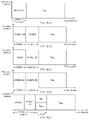
- FIG. 3 ( 1 ) and FIG. 3 ( 2 ) each are a schematic diagram of power allocation in different time-domain symbols on a PUSCH according to an embodiment of this application;
- FIG. 4 ( 1 ) and FIG. 4 ( 2 ) each are a schematic diagram of power allocation in different time-domain symbols on a PUSCH according to an embodiment of this application;
- FIG. 5 ( 1 ) and FIG. 5 ( 2 ) each are a schematic diagram of power allocation in different time-domain symbols on a PUSCH according to an embodiment of this application;
- FIG. 6 ( 1 ) and FIG. 6 ( 2 ) each are a schematic diagram of power allocation in different time-domain symbols on a PUSCH according to an embodiment of this application;
- FIG. 7 ( 1 ) and FIG. 7 ( 2 ) each are a schematic diagram of power allocation in different time-domain symbols on a PUSCH according to an embodiment of this application:
- FIG. 8 ( 1 ) to FIG. 8 ( 5 ) and FIG. 9 ( 1 ) and FIG. 9 ( 2 ) each are a schematic diagram of a structure for carrying an SR on a PUSCH according to an embodiment of this application;
- FIG. 10 is a schematic diagram of transmission of a PUCCH according to an embodiment of this application.
- FIG. 11 and FIG. 12 each are a schematic diagram of a structure for simultaneously transmitting a PUSCH and a PUCCH carrying only an SR according to an embodiment of this application;
- FIG. 13 , FIG. 14( a ) and FIG. 14( b ) , FIG. 15( a ) and FIG. 15( b ) , and FIG. 16( a ) to FIG. 16( c ) each are a schematic diagram of a structure for carrying an SR on a PUSCH according to an embodiment of this application;
- FIG. 17 is a schematic diagram of a structure when a long-duration PUCCH collides with a PUCCH carrying only an SR according to an embodiment of this application;
- FIG. 18 is a schematic diagram of a structure when a short-duration PUCCH collides with a PUCCH carrying only an SR according to an embodiment of this application:
- FIG. 19 is a schematic structural diagram of a terminal according to an embodiment of this application:
- FIG. 20 is a schematic structural diagram of a terminal according to an embodiment of this application.
- FIG. 21 is a schematic structural diagram of a data transmission apparatus according to an embodiment of this application.
- FIG. 1 shows an example of a system architecture to which this application is applicable.
- a base station may be a device that can communicate with a terminal.
- the base station may be any device with a wireless transceiver function, including but not limited to a base station (for example, a NodeB NodeB, an evolved NodeB eNodeB, a NodeB in a fifth generation (the fifth generation, 5G) communications system, a base station or a network device in a future communications system, an access node in a Wi-Fi system, a wireless relay node, and a wireless backhaul node), or the like.
- the base station may be a radio controller in a cloud radio access network (cloud radio access network, CRAN) scenario.
- the base station may be a network device on a 5G network or a network device on a future evolved network.
- the base station may be a wearable device, a vehicle-mounted device, or the like.
- the base station may be a small cell, a transmission node (transmission reference point, TRP), or the like. Certainly, this is not limited in this application.
- the terminal is a device with a wireless transceiver function.
- the terminal may be deployed on land and includes an indoor or outdoor device, a handheld device, a wearable device, or a vehicle-mounted device, may be deployed on a water surface (for example, a ship), or may be deployed in the air (for example, an airplane, a balloon, or a satellite).
- the terminal may be a mobile phone (mobile phone), a tablet computer (Pad), a computer with a wireless transceiver function, a virtual reality (Virtual Reality, VR) terminal device, an augmented reality (Augmented Reality, AR) terminal device, a wireless terminal in industrial control (industrial control), a wireless terminal in self driving (self driving), a wireless terminal in remote medical (remote medical), a wireless terminal in a smart grid (smart grid), a wireless terminal in transportation safety (transportation safety), and a wireless terminal in a smart city (smart city), a wireless terminal in a smart home (smart home), or the like.
- An application scenario is not limited in the embodiments of this application.
- the terminal may sometimes be referred to as user equipment (user equipment, UE), an access terminal device, a UE unit, a UE station, a mobile station, a mobile console, a remote station, a remote terminal device, a mobile device, a UE terminal device, a terminal device, a wireless communications device, a UE agent, a UE apparatus, or the like.
- user equipment user equipment
- UE user equipment
- an access terminal device a UE unit, a UE station, a mobile station, a mobile console, a remote station, a remote terminal device, a mobile device, a UE terminal device, a terminal device, a wireless communications device, a UE agent, a UE apparatus, or the like.
- a plurality of means two or more. In view of this, “a plurality of” may also be understood as “at least two” in the embodiments of the disclosure.
- the term “and/or” describes an association relationship between associated objects and represents that three relationships may exist. For example, A and/or B may represent the following three cases: Only A exists, both A and B exist, and only B exists. In addition, unless otherwise specified, the character “/” generally indicates an “or” relationship between the associated objects.
- a time domain resource in this application is one symbol or more consecutive symbols distributed in time domain.
- a frequency domain resource in this application is one or more subcarriers distributed in frequency domain, and a frequency domain resource element in this application is a subcarrier.
- a resource element (resource element, RE) in this application is a resource corresponding to one symbol in time domain and one subcarrier in frequency domain.
- a symbol described in this application includes but is not limited to an orthogonal frequency division multiplexing (OFDM) symbol, a sparse code multiple access (SCMA) symbol, a symbol, a filtered OFDM (F-OFDM) symbol, and a non-orthogonal multiple access (NOMA) symbol.
- OFDM orthogonal frequency division multiplexing
- SCMA sparse code multiple access
- F-OFDM filtered OFDM
- NOMA non-orthogonal multiple access
- a PUCCH in this application is a channel carrying control signaling sent by the terminal to the base station, and the control signaling includes control-related information.
- the PUCCH is used for replying with an Acknowledgment or a (acknowledge/negative acknowledge (ACK/NACK), transmitting uplink channel state information (CSI), or carrying a scheduling request.
- the physical uplink control channel is classified into two types. One is a long-duration PUCCH.
- the long-duration PUCCH occupies four to 14 consecutive OFDM symbols, and is transmitted in a frequency hopping manner.
- a demodulation reference signal (DMRS) and uplink control information are (UCI) are respectively carried in different symbols, and an orthogonal coverage code may be used for spreading on each frequency hopping part, to increase a capacity.
- DMRS demodulation reference signal
- UCI uplink control information
- the other is a short-duration PUCCH.
- the short-duration PUCCH occupies one or two OFDM symbols.
- information may be carried by using a sequence, or a DMRS and uplink control information UCI are transmitted in a frequency division manner by respectively occupying different subcarriers.
- the PUCCH may be transmitted on any location.
- An SR in this application is request signaling sent by the terminal to the base station when the terminal has an uplink transmission requirement, to obtain a time-frequency domain resource allocated by the base station.
- the base station configures, for the terminal, a resource used for transmitting the SR, where the resource is periodically allocated.
- the base station receives the SR from the terminal, the base station sends, to the terminal in proper time, downlink control signaling in which allocated resource information is carried, and then the terminal performs uplink transmission on the resource allocated by the base station.
- a scheduling request is carried in two manners. One manner is that the scheduling request is transmitted by the terminal on a resource periodically allocated by the base station.
- the other manner is that when feeding back other uplink control information, the terminal jointly encodes the SR and the other uplink control information for transmission.
- a physical uplink shared channel (Physical uplink shared channel, PUSCH) in this application is a channel used by the terminal to transmit data and some control information.
- PUSCH Physical uplink shared channel
- New radio NR
- a currently agreed-upon structure of the PUSCH is shown in FIG. 2 .
- a DMRS is carried in one or two start symbols on the PUSCH, to support channel measurement on a plurality of ports.
- the data or other control information is carried in remaining symbols on the PUSCH. In the remaining symbols, there is a fixed frequency domain resource used for carrying a phase tracking reference signal (phase tracking reference signal, PT-RS).
- the terminal transmits the same signal in the symbols to detect phase noise. Whether the PT-RS is carried on the PUSCH is preconfigured.
- this application provides an uplink transmission method, mainly including the following steps.
- Step 101 A terminal obtains a first transmit power and a second transmit power.
- the first transmit power and the second transmit power are respectively powers allocated by the terminal to a first uplink channel and a second uplink channel for transmission on a first time domain resource.
- a sum of the first transmit power and the second transmit power is equal to a total transmit power of the terminal on the first time domain resource.
- the first uplink channel is a PUCCH carrying only an SR.
- the second uplink channel may be a long-duration PUCCH, or may be a short-duration PUCCH, or may be a PUSCH. However, when the second uplink channel is the short-duration PUCCH, the short-duration PUCCH does not include a short-duration PUCCH carrying only the SR.
- the first uplink channel occupies the first time domain resource to transmit the SR.
- a length of the first time domain resource is a length of one symbol or a length of two symbols
- the length of one symbol is a time length occupied by one symbol
- the length of two symbols is a time length occupied by two consecutive symbols.
- the first uplink channel is a short-duration PUCCH.
- the first uplink channel is a PUCCH with a length of one symbol or a PUCCH with a length of two symbols.
- the first time domain resource is the same as some or all time domain resources occupied by the second uplink channel. In other words, the first time domain resource is included in the time domain resources occupied by the second uplink channel.
- Step 102 The terminal transmits the first uplink channel on the first time domain resource by using the first transmit power, and the terminal transmits the second uplink channel on the first time domain resource by using the second transmit power.
- transmitting the second uplink channel on the first time domain resource means that information is transmitted on a resource that is configured for the second uplink channel and that corresponds to the first time domain resource.
- the information is information that is carried on the second uplink channel on the resource corresponding to the first time domain resource.
- transmitting the first uplink channel on the first time domain resource means that the SR is transmitted on a resource that is allocated to the first uplink channel and that corresponds to the first time domain resource.
- the resource that is configured for the second uplink channel and that corresponds to the first time domain resource is different from the resource that is configured for the first uplink channel and that corresponds to the first time domain resource.
- the resource that is configured for the second uplink channel and that corresponds to the first time domain resource includes one or more resource elements.
- the resource element that is configured for the second uplink channel and that corresponds to the first time domain resource is preconfigured by a base station, or is preconfigured on the terminal.
- the resource that is configured for the first uplink channel and that corresponds to the first time domain resource includes one or more resource elements.
- the resource that is allocated to the first uplink channel and that corresponds to the first time domain resource is preconfigured by the base station, or is preconfigured on the terminal.
- the terminal allocates the first transmit power and the second transmit power to the same time domain resource occupied by the first uplink channel and the second uplink channel, so that the first uplink channel and the second uplink channel can be simultaneously transmitted on the same time domain resource.
- the configured first transmit power is different from the configured second transmit power based on a transmission characteristic of the same time domain resource in the time domain resources occupied by the second uplink channel.
- the second uplink channel is a PUSCH, and a length of the PUSCH is not limited.
- a function of the PUSCH is to transmit a DMRS and data. Therefore, based on different cases of the first time domain resource included in time domain resources used for the PUSCH, that the terminal transmits the second uplink channel on the first time domain resource by using the second transmit power in step 102 also includes different cases. For example, if the first time domain resource included in the time domain resources used for the PUSCH occupies only a DMRS symbol, the terminal transmits the DMRS on the first time domain resource by using the second transmit power. If the first time domain resource included in the time domain resources used for the PUSCH occupies only a data symbol, the terminal transmits the data on the first time domain resource by using the second transmit power. If the first time domain resource included in the time domain resources used for the PUSCH occupies both a DMRS symbol and a data symbol, the terminal transmits both the DMRS and the data on the first time domain resource by using the second transmit power.
- the first transmit power and the second transmit power also have different configurations.
- the first transmit power is not less than a transmit power required for the SR, and the second transmit power is a difference between the total transmit power of the terminal on the first time domain resource and the first transmit power.
- the first uplink channel occupies a time domain resource with a length of one symbol to transmit the SR
- the PUSCH occupies a time domain resource with a length of one symbol or two symbols to transmit the DMRS.
- the symbol for carrying the SR on the first uplink channel is the same as the 1 st symbol for carrying the DMRS on the PUSCH in time domain
- the transmit power required for the DMRS is P0
- the transmit power required for the SR is P1
- a total transmit power of the terminal in each symbol is P
- the terminal configures the total transmit power P in the same symbol as the first transmit power P1 and the second transmit power (P-P1).
- P1 can meet at least a transmission requirement of the SR carried on the first uplink channel.
- the second transmit power (P-P1) may meet a transmission requirement of the DMRS carried on the PUSCH, or may not meet a transmission requirement of the DMRS carried on the PUSCH.
- the second transmit power is the same as a transmit power for the 1 st DMRS, and the first transmit power is a difference between the total transmit power of the terminal on the first time domain resource and the second transmit power.
- the first uplink channel occupies a time domain resource with a length of one symbol to transmit the SR
- the PUSCH occupies a time domain resource with a length of two symbols to transmit the DMRS.
- the symbol for carrying the SR on the first uplink channel is the same as the 2 nd symbol for carrying the DMRS on the PUSCH in time domain
- a transmit power required for the DMRS is P0
- a transmit power required for the SR is P1
- a total transmit power of the terminal in each symbol is P
- the terminal configures the total transmit power P in the same symbol as the first transmit power (P-P0) and the second transmit power P0.
- P0 is a transmit power in the 1 st symbol for carrying the DMRS on the PUSCH, and P0 can meet at least a transmission requirement of the DMRS carried on the PUSCH.
- the first transmit power (P-P0) may meet a transmission requirement of the SR carried on the first uplink channel, or may not meet a transmission requirement of the SR carried on the first uplink channel.
- the first transmit power is not less than a transmit power required for the SR
- the second transmit power is a difference between the total transmit power of the terminal on the first time domain resource and the first transmit power.
- the base station obtains variations of transmit powers in different data symbols by comparing variations of transmit powers on a frequency domain resource occupied by PT-RSs in the different data symbols.
- the first uplink channel occupies a time domain resource with a length of one symbol to transmit the SR
- the PUSCH occupies a time domain resource with a length of 2 to 13 symbols to transmit the data.
- the symbol for carrying the SR on the first uplink channel overlaps with one of the symbols for carrying the data on the PUSCH in time domain, and when a transmit power required for the DMRS is P0, the transmit power required for the SR is P1, and a total transmit power of the terminal in each symbol is P
- the terminal configures the total transmit power P in the overlapping symbol as the first transmit power P1 and the second transmit power (P-P1).
- the second transmit power (P-P1) may meet a transmission requirement of the DMRS carried on the PUSCH, or may not meet a transmission requirement of the DMRS carried on the PUSCH.
- the second transmit power is the same as a transmit power on a time domain resource used for carrying the DMRS on the PUSCH, and the first transmit power is a difference between the total transmit power of the terminal on the first time domain resource and the second transmit power.
- the first uplink channel occupies a time domain resource with a length of one symbol to transmit the SR
- the PUSCH occupies a time domain resource with a length of 1 to 13 symbols to transmit the data.
- the transmit power required for the DMRS is P0
- a transmit power required for the SR is P1
- a total transmit power of the terminal in each symbol is P
- the terminal configures the total transmit power P in the overlapping symbol as the first transmit power (P-P0) and the second transmit power P0.
- the first transmit power (P-P0) may meet a transmission requirement of the SR carried on the first uplink channel, or may not meet a transmission requirement of the SR carried on the first uplink channel.
- a symbol length of a time domain resource occupied by the PUSCH is not limited, and the length may be long duration or short duration.
- the symbol length of the time domain resource occupied by the PUSCH may be preconfigured on the terminal, or may be indicated by the base station to the terminal.
- an SR period is relatively short, and may be flexibly configured based on different services.
- the SR period includes a length of at least one symbol, and the SR period may be preconfigured on the terminal, or may be indicated by the base station to the terminal.
- a manner of configuring the first transmit power and the second transmit power may be one of the foregoing several optional configuration manners, or may be a combination of any two or three of the foregoing several optional configuration manners.
- a transmit power for data carried on the PUSCH in the data symbol after the DMRS symbol is configured as follows:
- the transmit power for the data carried in the data symbol is the same as the second transmit power.
- the transmit power required for the DMRS is P0
- the transmit power required for the SR is P1
- the total transmit power of the terminal in each symbol is P.
- the transmit power allocated to the SR may be P1
- the transmit power allocated to the DMRS may be P-P1
- the transmit power for the data carried in the data symbol may be P-P1.
- a transmit power for the 1 st DMRS may be P0
- the transmit power allocated to the SR may be P-P0
- the transmit power allocated to the DMRS may be P0
- the transmit power for the data carried in the data symbol may be P0.
- a transmit power for data carried in each data symbol increases relative to the second transmit power based on a specified proportion.
- the base station may either identify an increment in the transmit power in the data symbol, or obtain an increment in the transmit power in the data symbol by comparing variations of transmit powers for the PT-RS and the DMRS on a same frequency domain resource.
- the transmit power required for the DMRS is P0
- the transmit power required for the SR is P1
- the total transmit power of the terminal in each symbol is P.
- the transmit power allocated to the SR may be P1
- the transmit power allocated to the DMRS may be P-P1
- the transmit power for the data carried in the data symbol may be x*(P-P1), where x is greater than or equal to 1, and x is an integer or not an integer.
- a transmit power for the 1 st DMRS may be P0
- the transmit power allocated to the SR may be P-P0
- the transmit power allocated to the DMRS may be P0
- the transmit power for the data carried in the data symbol may be x*P0.
- the transmit power for the data carried in the data symbol keeps the same as the second transmit power.
- the transmit power for the data carried in the data symbol keeps the same as the second transmit power.
- a transmit power for data carried on the PUSCH in the data symbol after the DMRS symbol is configured as follows:
- a transmit power for carrying the SR on the first uplink channel in a next period is the transmit power required for the SR
- a transmit power in the same data symbol is a difference between a total transmit power of the terminal in the data symbol and the transmit power for carrying the SR on the first uplink channel in the next period
- a transmit power for data in a remaining data symbol may be the same as the transmit power for the DMRS, or may proportionally increase relative to the transmit power for the DMRS.
- the base station obtains variations of transmit powers in different data symbols by comparing variations of transmit powers on a frequency domain resource occupied by PT-RSs in the different data symbols.
- the transmit power required for the DMRS is P0
- the transmit power required for the SR is P1
- the total transmit power of the terminal in each symbol is P.
- a transmit power allocated to the SR in the 1 st symbol may be P1
- a transmit power allocated to the DMRS in the 1 st symbol may be P-P1.
- the transmit power for carrying the SR on the PUCCH in the next period may be P1
- a transmit power in the data symbol may be P-P1
- a transmit power for data carried in a remaining data symbol may be P-P1.
- a transmit power for the 1 st DMRS may be P0
- the transmit power allocated to the SR may be P-P0
- the transmit power allocated to the DMRS may be P.
- the transmit power for carrying the SR on the PUCCH in the next period may be P1
- a transmit power in the data symbol may be P-P1
- a transmit power for data carried in a remaining data symbol may be P0.
- the transmit power for the data carried in the data symbol keeps the same as the transmit power required for carrying the DMRS on the PUSCH, and a transmit power in the symbol for carrying the SR on the first uplink channel in a next period is a difference between a total transmit power of the terminal in the data symbol and a transmit power in the overlapping data symbol.
- the transmit power required for the DMRS is P0
- the transmit power required for the SR is P1
- the total transmit power of the terminal in each symbol is P.
- a transmit power allocated to the SR in the 1 st symbol may be P1
- a transmit power allocated to the DMRS in the 1 st symbol may be P-P1.
- the transmit power for carrying the SR on the PUCCH in the next period may be P-P0, a transmit power in the same data symbol may be P0, and a transmit power for data carried in a remaining data symbol may be P-P1.
- a transmit power for the 1 st DMRS may be P0, the transmit power allocated to the SR may be P-P0, and the transmit power allocated to the DMRS may be P0.
- the transmit power for carrying the SR on the PUCCH in the next period may be P-P0, a transmit power in the data symbol may be P0, and a transmit power for data carried in a remaining data symbol may be P0.
- a transmit power for carrying the SR on the first uplink channel in a next period is the transmit power required for the SR
- the transmit power in the data symbol is a difference between a total transmit power of the terminal in the data symbol and the transmit power for carrying the SR on the first uplink channel in the next period.
- the transmit power required for the DMRS is P0
- the transmit power required for the SR is P1
- the total transmit power of the terminal in each symbol is P.
- a transmit power allocated to the SR in the 1 st symbol may be P1
- a transmit power allocated to the DMRS in the 1 st symbol may be P-P1.
- the transmit power for carrying the SR on the PUCCH in the next period may be P1
- a transmit power in the same data symbol may be P-P1
- a transmit power for data carried in a remaining data symbol may be P-P.
- a transmit power for the 1 st DMRS may be P0
- the transmit power allocated to the SR may be P-P0
- the transmit power allocated to the DMRS may be P0.
- the transmit power for carrying the SR on the PUCCH in the next period may be P1
- a transmit power in the same data symbol may be P-P1
- a transmit power for data carried in a remaining data symbol may be P0.
- the second uplink channel is a PUCCH
- the second uplink channel may be a long-duration PUCCH shown in FIG. 17 , or may be a short-duration PUCCH shown in FIG. 18 .
- the long-duration PUCCH is a PUCCH with a length of 4 to 14 symbols
- the short-duration PUCCH may be a PUCCH with a length of one symbol or a PUCCH with a length of two symbols.
- that the terminal transmits the second uplink channel on the first time domain resource by using the second transmit power in step 102 means that the terminal transmits, on the resource that is allocated to the second uplink channel and that corresponds to the first time domain resource, uplink control information that is carried on the second uplink channel on the first time domain resource.
- information carried on the long-duration PUCCH may be uplink control information other than the SR, such as an ACK/a NACK and a CQI, or may be the SR and the uplink control information.
- Information carried on the short-duration PUCCH may be uplink control information other than the SR, such as an ACK/a NACK and a CQI, or may be the SR and the uplink control information. In this application, a case in which the short-duration PUCCH carries only the SR is not included.
- the long-duration PUCCH is classified into two types: a long-duration PUCCH on which an OCC is used to perform multi-user multiplexing and a long-duration PUCCH on which an OCC is not used to perform multi-user multiplexing.
- a long-duration PUCCH on which an OCC is used to perform multi-user multiplexing and a long-duration PUCCH on which an OCC is not used to perform multi-user multiplexing.
- the short-duration PUCCH is classified into three types: a short-duration PUCCH that occupies a single symbol, a short-duration PUCCH that occupies a short-duration PUCCH with two symbols for performing joint encoding, and a short-duration PUCCH that occupies a short-duration PUCCH on which an OCC is enabled by using two symbols. If the short-duration PUCCH is the short-duration PUCCH on which the OCC is enabled by using two symbols, a requirement for a transmit power for information carried in each symbol keeps unchanged, to avoid interference between a plurality of users.
- the second uplink channel is the long-duration PUCCH (as shown in FIG. 17 )
- the first transmit power and the second transmit power that are respectively allocated by the terminal to the first uplink channel and the second uplink channel also have different configurations. Details are as follows:
- the first transmit power is not less than the transmit power required for the SR
- the second transmit power is the difference between the total transmit power of the terminal on the first time domain resource and the first transmit power.
- the long-duration PUCCH occupies 14 symbols, and the first uplink channel occupies one symbol. It is assumed that the transmit power required for the SR is P1, a transmit power for the long-duration PUCCH in each symbol is P2, and a total transmit power of the terminal on the long-duration PUCCH in each symbol is P.
- the transmit power allocated to the SR may be P1
- a transmit power allocated to uplink control information carried on the long-duration PUCCH in the 1 st symbol may be P-P1
- a transmit power for uplink control information carried in each of the 2 nd symbol to the 7 th symbol is the same as the transmit power for the information carried in the 1 st symbol, where both may be P-P1.
- the transmit power allocated to the SR may be P1
- a transmit power allocated to uplink control information carried on the long-duration PUCCH in the 8 th symbol may be P-P1
- a transmit power for uplink control information carried in each of the 9 th symbol to the 14 th symbol is the same as the transmit power for the information carried in the 8 th symbol, where both may be P-P1.
- the first time domain resource is the same as a time domain resource after a start time domain resource used for the second uplink channel or a time domain resource after a start time domain resource used for the second uplink channel in frequency hopping
- the second transmit power is the same as a transmit power of the terminal on the start time domain resource
- the first transmit power is the difference between the total transmit power of the terminal on the first time domain resource and the second transmit power.
- the long-duration PUCCH occupies 14 symbols, and the first uplink channel occupies one symbol. It is assumed that the transmit power required for the SR is P1, a transmit power for the long-duration PUCCH in each symbol is P2, and a total transmit power of the terminal in each symbol is P.
- the transmit power allocated to the SR may be P-P2, and a transmit power for information carried on the long-duration PUCCH in each symbol may be P2.
- the transmit power allocated to the SR may be P-P2
- a transmit power for information carried on the long-duration PUCCH in each symbol may be P2.
- the first transmit power is not less than the transmit power required for the SR
- the second transmit power is the difference between the total transmit power of the terminal on the first time domain resource and the first transmit power.
- the long-duration PUCCH occupies 14 symbols, and the first uplink channel occupies one symbol. It is assumed that the transmit power required for the SR is P1, a transmit power for the long-duration PUCCH in each symbol is P2, and a total transmit power of the terminal in each symbol is P.
- the transmit power allocated to the SR is at least P1, and a transmit power allocated to uplink control information carried on the long-duration PUCCH in the overlapping symbol is P-P1.
- a transmit power for the long-duration PUCCH in another symbol may be P2, or may be P-P1.
- the first uplink channel may collide once with the long-duration PUCCH in a length of the symbols occupied by the PUCCH, or the first uplink channel may collide a plurality of times with the long-duration PUCCH in a length of the symbols occupied by the PUCCH. Therefore, in another implementation scenario, a case of the first time domain resource included in the time domain resources occupied by the second uplink channel may be any combination of the foregoing several cases.
- the symbol for carrying the SR on the first uplink channel may overlap with a symbol on the long-duration PUCCH on a location of one of or a combination of any two or three of the 1 st symbol on the long-duration PUCCH, the 1 st symbol on the long-duration PUCCH in frequency hopping, a symbol other than the 1 st symbol on the long-duration PUCCH, or a symbol other than the 1 st symbol on the long-duration PUCCH in frequency hopping.
- a manner of configuring the first transmit power and the second transmit power may include one of the foregoing several optional configuration manners, or may include any combination of the foregoing several optional configuration manners.
- the first transmit power and the second transmit power also have different configurations. Details are as follows:
- the first transmit power is not less than the transmit power required for the SR
- the second transmit power is the difference between the total transmit power of the terminal on the first time domain resource and the first transmit power.
- the second transmit power is not less than a transmit power required for the second uplink channel
- the first transmit power is the difference between the total transmit power of the terminal on the first time domain resource and the second transmit power.
- the first transmit power is equal to the second transmit power
- the first transmit power and the second transmit power are obtained by the terminal by allocating the total transmit power of the terminal on the first time domain resource according to an equal allocation principle.
- the first transmit power and the second transmit power are obtained by allocating the total power based on a ratio of an information amount of the SR to an information amount of uplink control information carried on the second uplink channel.
- the first transmit power and the second transmit power also have different configurations. Details are as follows:
- the first transmit power is not less than a transmit power required for the first uplink channel, and the second transmit power is the difference between the total transmit power of the terminal on the first time domain resource and the first transmit power; or the second transmit power is not less than the transmit power required for the second uplink channel, and the first transmit power is the difference between the total transmit power of the terminal on the first time domain resource and the second transmit power.
- the second transmit power is the same as a transmit power on the 1 st time domain resource used for the second uplink channel, and the first transmit power is the difference between the total transmit power of the terminal on the first time domain resource and the second transmit power.
- the first uplink channel may collide once with the short-duration PUCCH on the time domain resources occupied by the short-duration PUCCH, or the first uplink channel may collide a plurality of times with the short-duration PUCCH in a length of symbols occupied by the short-duration PUCCH. Therefore, in another implementation scenario, a case of the first time domain resource included in the time domain resources occupied by the second uplink channel may be any combination of the foregoing several cases.
- a manner of configuring the first transmit power and the second transmit power may include one of the foregoing several optional configuration manners, or may include any combination of the foregoing several optional configuration manners.
- the terminal transmits the SR on the first time domain resource.
- the terminal transmits the second uplink channel, or the transmit power for the second uplink channel is 0.
- the terminal transmits the SR on the first time domain resource.
- time domain resources on which the second uplink channel is not transmitted or has been transmitted include time domain resources respectively used for carrying the DMRS and the uplink control information (for example, UCI)
- the terminal transmits the second uplink channel.
- time domain resources on which the second uplink channel is not transmitted or has been transmitted do not include time domain resources used for carrying the DMRS and the uplink control information, the transmit power for the second uplink channel is 0.
- the terminal transmits the second uplink channel on the first time domain resource.
- a transmit power for information carried on a time domain resource that is used for the second uplink channel and that is different from the first time domain resource used for the first uplink channel is the same as the second transmit power.
- a transmit power for information carried on a time domain resource that is used for the second uplink channel and that is different from the first time domain resource used for the first uplink channel proportionally increases relative to the second transmit power.
- the time domain resource used for the first uplink channel may collide with some or all time domain resources used for the PUSCH, the time domain resource used for the first uplink channel may collide with some or all time domain resources used for the long-duration PUCCH, the time domain resource used for the first uplink channel may collide with some or all time domain resources used for the short-duration PUCCH, or the time domain resource used for the first uplink channel may collide with one of or any two or three of those used for the PUSCH, the long-duration PUCCH, or the short-duration PUCCH.
- a case of the first time domain resource included in the time domain resources occupied by the second uplink channel may be any combination of the different cases in the foregoing several implementation scenarios.
- a manner of configuring the first transmit power and the second transmit power may include one of the configuration manners in the foregoing several implementation scenarios, or may include any combination of the configuration manners in the foregoing several implementation scenarios.
- this application further provides another uplink transmission method, mainly including the following steps.
- Step 201 A terminal obtains a first time domain resource and a first frequency domain resource, and obtains a second time domain resource and a second frequency domain resource.
- Both the first frequency domain resource and the second frequency domain resource are included in frequency domain resources configured by a base station for a PUSCH, and the second time domain resource is included in the first time domain resource.
- Step 202 The terminal sends the information by using the first time domain resource and the first frequency domain resource, where the information includes a DMRS and/or data carried on the PUSCH; and the terminal sends the scheduling request SR by using the second time domain resource and the second frequency domain resource.
- That the terminal sends the information by using the first frequency domain resource and the first time domain resource in step 202 includes the following cases:
- the terminal sends the DMRS on the PUSCH by using the first frequency domain resource and the first time domain resource, or the terminal sends the data on the PUSCH by using the first frequency domain resource and the first time domain resource, or the terminal sends both the DMRS and the data on the PUSCH by using the first frequency domain resource and the first time domain resource.
- a possible relationship between the first time domain resource and the second time domain resource is as follows:
- All time domain resources of the second time domain resource are the same as all or some time domain resources of the first time domain resource, or some time domain resources of the second time domain resource are the same as all or some time domain resources of the first time domain resource.
- a length of the first time domain resource is a length of a symbol occupied by a PUCCH, and is preconfigured by the base station for the terminal or prestored on the terminal.
- the length may be a length of one symbol, a length of two symbols, or a length greater than two symbols.
- the SR is periodically sent, and a symbol length of the second time domain resource is related to an SR period and a length of a symbol occupied by each SR.
- the length of the symbol occupied by each SR is a length of one symbol or a length of two symbols.
- the SR period may be flexibly configured.
- the SR period is preconfigured by the base station for the terminal, or prestored on the terminal.
- the SR period may be a length of one symbol or a length greater than or equal to two symbols. If the SR period is greater than or equal to the length of the first time domain resource, there may be one SR sending period in the length of the first time domain resource. In this case, the length of the second time domain resource is a length of one symbol occupied by the SR. If the SR period is less than the length of the first time domain resource, there may be a plurality of SR sending periods in the length of the first time domain resource. In this case, the length of the second time domain resource is greater than a length of one symbol or greater than a length of two symbols.
- a time domain resource used by the terminal to send the DMRS on the PUSCH may be the same as the time domain resource used by the terminal to send the SR in time domain
- a time domain resource used by the terminal to send the data on the PUSCH may be the same as the time domain resource used by the terminal to send the SR in time domain
- both a time domain resource used by the terminal to send the data on the PUSCH and a time domain resource used by the terminal to send the DMRS on the PUSCH may be the same in time domain as the time domain resource used for sending the SR.
- the terminal may send the SR in one or more data symbols on the PUSCH, the terminal may send the SR in one or two DMRS symbols on the PUSCH, or the terminal sends the SR in both one or more data symbols and one or two DMRS symbols.
- all time domain resources of the second time domain resource are the same as all time domain resources of the first time domain resource.
- the first time domain resource fully overlaps with the second time domain resource in time domain.
- the SR period is the length of one symbol. Regardless of whether the length of the symbol occupied by each SR is the length of one symbol or the length of two symbols, the SR may be sent on the PUSCH in each symbol. In this case, the length of the second time domain resource is the same as the length of the first time domain resource.
- all time domain resources of the second time domain resource are the same as some time domain resources of the first time domain resource.
- all time domain resources of the second time domain resource overlap with some time domain resources of the first time domain resource in time domain.
- the SR period is the length of two symbols, and the SR period is less than the length of the first time domain resource.
- the SR may be sent at an interval of a length of two symbols in a symbol length of the PUSCH. If the length of the symbol occupied by each SR is the length of one symbol, the SR is sent in some symbols on the PUSCH. In this case, all time domain resources of the second time domain resource overlap with some time domain resources of the first time domain resource in time domain.
- some time domain resources of the second time domain resource are the same as all time domain resources of the first time domain resource.
- some time domain resources of the second time domain resource overlap with all time domain resources of the first time domain resource in time domain.
- the SR period is greater than the length of the first time domain resource
- the second time domain resource has a length of two symbols
- the first time domain resource has a length of one symbol
- a length in time domain of one of the symbols of the second time domain resource overlaps with the length in time domain of the symbol of the first time domain resource.
- some time domain resources of the second time domain resource are the same as some time domain resources of the first time domain resource.
- some time domain resources of the second time domain resource overlap with some time domain resources of the first time domain resource in time domain.
- the SR period is the length of two symbols, and the SR period is less than the length of the first time domain resource.
- the SR may be sent at an interval of a length of two symbols in a symbol length of the PUSCH. If the length of the symbol occupied by each SR is the length of two symbols, the 2 nd symbol of the second time domain resource overlaps with the 1 st symbol of the first time domain resource in time domain. In this case, the SR is sent in some symbols on the PUSCH, and some of the second time domain resources overlap with some of the first time domain resources in time domain.
- the length of the second time domain resource is the length of two symbols
- the length of the first time domain resource is greater than or equal to the length of two symbols
- a length in time domain of one of the symbols in time domain of the second time domain resource overlaps with a length of one of the symbols of the first time domain resource.
- the second time domain resource and the second frequency domain resource that are used to send the SR are some resources that are in resources configured for the PUSCH and that are reserved for the SR.
- the SR is carried on the PUSCH for transmission in the foregoing method procedure. This further resolves a prior-art signal transmission problem that arises when the short-duration PUCCH carrying only the SR collides with another uplink channel on a same time domain resource.
- the first frequency domain resource when the terminal sends the DMRS on the PUSCH by using the first frequency domain resource and the first time domain resource, the first frequency domain resource includes a frequency domain resource occupied by the DMRS on the PUSCH, and the first time domain resource includes a time domain resource occupied by the DMRS on the PUSCH.
- all frequency domain resources of the second frequency domain resource are the same as all or some frequency domain resources of the first frequency domain resource, or some frequency domain resources of the second frequency domain resource are the same as all or some frequency domain resources of the first frequency domain resource.
- a frequency domain resource occupied by the SR may be the same as all frequency domain resources occupied by the DMRS, or a frequency domain resource occupied by the SR may be the same as some frequency domain resources occupied by the DMRS.
- a frequency domain resource occupied by the SR is the same as some or all frequency domain resources occupied by the 1 st DMRS.
- a frequency domain resource occupied by the SR is the same as some or all frequency domain resources occupied by the 2 nd DMRS.
- the first frequency domain resource when the terminal sends the data on the PUSCH by using the first frequency domain resource and the first time domain resource, the first frequency domain resource includes a frequency domain resource occupied by the data on the PUSCH, and the first time domain resource includes a time domain resource occupied by the data on the PUSCH.
- the first frequency domain resource is different from the second frequency domain resource.
- the second frequency domain resource is a frequency domain resource that is in frequency domain resources configured by the base station for the PUCCH and that is reserved and specially used to send the SR, and a remaining frequency domain resource is the first frequency domain resource. Therefore, that the second frequency domain resource is different from the first frequency domain resource means that in the frequency domain resources configured by the base station for the PUCCH, the first frequency domain resource is different from the second frequency domain resource. In addition, that the first frequency domain resource is different from the second frequency domain resource may be further understood from a perspective of use frequencies corresponding to the frequency domain resources. To be specific, a frequency of the second frequency domain resource is greater than or equal to a minimum frequency of the first frequency domain resource, and the frequency of the second frequency domain resource is less than or equal to a maximum frequency of the first frequency domain resource.
- the first frequency domain resource includes a frequency domain resource occupied by the DMRS on the PUSCH and a frequency domain resource occupied by the data on the PUSCH
- the first time domain resource includes a time domain resource occupied by the DMRS on the PUSCH and a time domain resource occupied by the data on the PUSCH.
- the first frequency domain resource may be partially the same as the second frequency domain resource.
- the terminal when the time domain resource used by the terminal to send the DMRS on the PUSCH is the same as the time domain resource used by the terminal to send the SR, the terminal simultaneously sends the DMRS and the SR by using a frequency domain resource corresponding to the same time domain resource.
- time domain resource occupied by the DMRS is the same as the time domain resource occupied by the SR, the following several cases are mainly included:
- a frequency domain resource occupied by the DMRS may be the same as a frequency domain resource occupied by the SR, or some frequency domain resources occupied by the DMRS are the same as a frequency domain resource occupied by the SR.
- both the SR and the DMRS are carried on the PUSCH in a DMRS symbol.
- the DMRS symbol occupies one symbol, and the SR and the DMRS occupies a same frequency domain resource.
- a length of a symbol occupied by the SR is a length of one symbol
- a length of a symbol occupied by the DMRS is a length of two symbols
- the length of one symbol occupied by the SR is the same as a length of the 1 st symbol occupied by the DMRS in time domain
- some frequency domain resources occupied by the DMRS are the same as a frequency domain resource occupied by the SR.
- the DMRS occupies two symbols on the PUSCH, and both the SR and the DMRS are carried on the PUSCH in the 1 st DMRS symbol.
- the frequency domain resource occupied by the SR may be the same as some frequency domain resources occupied by the 1 st DMRS, or may be the same as all frequency domain resources occupied by the 1 st DMRS.
- the 2 nd DMRS symbol is used to carry only the DMRS.
- a length of a symbol occupied by the SR is a length of one symbol
- a length of a symbol occupied by the DMRS is a length of two symbols
- the length of one symbol occupied by the SR is the same as a length of the 2 nd symbol occupied by the DMRS in time domain
- some frequency domain resources occupied by the DMRS are the same as a frequency domain resource occupied by the SR.
- the DMRS occupies two symbols on the PUSCH, the 1 st DMRS symbol is used to carry only the DMRS, and the 2 nd DMRS symbol is used to carry the SR and the DMRS.
- the frequency domain resource occupied by the SR may be the same as some frequency domain resources occupied by the 2 nd DMRS, or may be the same as all frequency domain resources occupied by the 2 nd DMRS.
- a frequency domain resource occupied by the DMRS is the same as a frequency domain resource occupied by the SR.
- the DMRS occupies two symbols on the PUSCH, the 1 st DMRS symbol is used to carry the SR and the DMRS, and the 2 nd DMRS symbol is used to carry the SR and the DMRS.
- the frequency domain resource occupied by the SR may be the same as all frequency domain resources occupied by the DMRS, or may be the same as some frequency domain resources occupied by the DMRS.
- a length of a symbol occupied by the SR is a length of two symbols
- a length of a symbol occupied by the DMRS is a length of two symbols
- a length of the 1 st symbol occupied by the SR is the same as a length of the 2 nd symbol occupied by the DMRS in time domain
- a frequency domain resource occupied by the DMRS is the same as a frequency domain resource occupied by the SR.
- the DMRS occupies two symbols on the PUSCH, the 1 st DMRS symbol is used to carry only the DMRS, and the 2 nd DMRS symbol is used to carry the SR and the DMRS.
- the frequency domain resource occupied by the SR may be the same as some frequency domain resources occupied by the 2 nd DMRS, or may be the same as all frequency domain resources occupied by the 2 nd DMRS.
- the 1 data symbol after the 2 nd DMRS symbol is used to carry the data and the SR. However, the data and the SR occupy different frequency domain resources.
- the terminal when the time domain resource occupied by the DMRS is the same as the time domain resource occupied by the SR, on the same time domain resource, the terminal sends the DMRS by using a first sequence, and sends the SR by using a second sequence, where the first sequence is different from the second sequence.
- first time sequence and the second time sequence are orthogonal on the entire PUSCH.
- first time sequence and the second time sequence are orthogonal in an overlapping DMRS symbol.
- the terminal when the time domain resource occupied by the DMRS is the same as the time domain resource occupied by the SR, on the same time domain resource, the terminal sends the DMRS by using a first transmit power, and the terminal sends the SR by using a second transmit power.
- the second transmit power is 0, and the first transmit power is not less than a transmit power required for the DMRS.
- the second transmit power is not less than a transmit power required for transmitting the SR, and the first transmit power is a difference between a total transmit power of the terminal on the second time domain resource and the second transmit power.
- the second transmit power is not less than a transmit power required for transmitting the SR
- the first transmit power is a difference between a total transmit power of the terminal on the second time domain resource and the second transmit power.
- the first transmit power is the same as a transmit power for the 1 st DMRS
- the second transmit power is a difference between a total transmit power of the terminal on the second time domain resource and the first transmit power.
- the transmit power required for the SR is P1
- the transmit power required for the DMRS is P0
- a total transmit power of the terminal in each symbol length is P.
- the terminal sends the SR in the DMRS symbol by using the second sequence
- the terminal sends the DMRS in the DMRS symbol by using the first sequence.
- the transmit power for sending the SR is greater than or equal to P1
- the transmit power for transmitting the DMRS is less than or equal to P-P1.
- the terminal sends the SR in the 1 st DMRS symbol by using the second sequence, and the terminal sends the 1 st DMRS in the 1 st DMRS symbol by using the first sequence.
- the transmit power for sending the SR is greater than or equal to P1, and a transmit power for sending the 1 st DMRS is less than or equal to P-P1.
- the terminal sends the 2 nd DMRS in the 2 nd DMRS symbol.
- a transmit power for sending the 2 nd DMRS may be the same as the transmit power for sending the 1 st DMRS.
- the terminal sends the 1 st DMRS in the 1 st DMRS symbol.
- a transmit power for sending the 1 st DMRS is at least P0.
- the terminal sends the SR in the 2 nd DMRS symbol by using the second sequence, and the terminal sends the 2 nd DMRS in the 2 nd DMRS symbol by using the first sequence.
- the transmit power for sending the SR is P-P0, and a transmit power for sending the 2 nd DMRS is the same as the transmit power for sending the 1 st DMRS, that is, P0.
- the terminal sends the SR in the 1 st DMRS symbol and the 2 nd DMRS symbol by using the second sequence, and the terminal sends the DMRS in the 1 st DMRS symbol and the 2 nd DMRS symbol by using the first sequence.
- the transmit power for sending the SR is greater than or equal to P1
- the transmit power for sending the DMRS is less than or equal to P-P1.
- the terminal sends the 1 st DMRS in the 1 st DMRS symbol.
- a transmit power for sending the 1l DMRS is at least P0.
- the terminal sends the SR in the 2 nd DMRS symbol by using the second sequence, and the terminal sends the 2 nd DMRS in the 2 nd DMRS symbol by using the first sequence.
- the transmit power for sending the SR is P-P0, and a transmit power for sending the 2 nd DMRS is the same as the transmit power for sending the 1 st DMRS, that is, P0.
- the terminal further sends the SR and the data in a data symbol after the 2 nd DMRS symbol. However, the SR and the data occupy different frequency domain resources.
- the terminal when some or all time domain resources used by the terminal to send the data are the same as the time domain resource used by the terminal to send the SR in time domain, the terminal sends the SR and the data on the same time domain resource by respectively using different resources.
- a resource occupied by the data in resources corresponding to the same time domain resource occupied by the data and the SR, a resource occupied by the data is different from a resource occupied by the SR.
- a frequency of the resource occupied by the SR is greater than or equal to a minimum frequency of the resource occupied by the data, and a frequency of the resource occupied by the data is less than or equal to a maximum frequency of the resource occupied by the data.
- the resource occupied by the SR includes one or more resource groups, and each resource group includes one RE or at least two consecutive REs.
- a resource group used for carrying the data symbols and a resource group used for carrying the SR are located on different frequency domain resources.
- the terminal adds the SR to at least two data symbols on the PUSCH, and a resource used for carrying the SR is different from a resource used for carrying the data.
- the resource used for carrying the SR may be set adjacent to a frequency domain resource occupied by a PT-RS, may be set on a same side of a frequency domain resource occupied by a PT-RS, or may be set on different sides of a frequency domain resource occupied by a PT-RS.
- a resource corresponding to a same symbol there may be two or more resource groups used for carrying the SR.
- the frequency domain resource occupied by the SR includes a plurality of resource groups, there is an interval of at least one RE between different resource groups.
- the terminal when the terminal sends the SR in one of the data symbols on the PUSCH, in a resource corresponding to the data symbol, there are three resource groups used for carrying the SR, and there is an interval of at least one RE between the three resource groups.
- a frequency diversity manner may be used.
- adjacent resource groups that are located on the time domain resource and that are reserved for the SR are located on different frequency domain resources.
- resource groups used for carrying the SR in the two consecutive data symbols are located on different frequency domain resources.
- resource groups used for carrying the SR in two adjacent data symbols are located on different frequency domain resources.
- the terminal sends the SR in all data symbols on the PUSCH, and there are two resource groups used for carrying the SR in each data symbol, four resource groups used for carrying the SR in two adjacent data symbols are located on different frequency domain resources.
- the information further includes a phase tracking reference signal
- at least one of the resource groups used for carrying the SR is adjacent to a frequency domain resource occupied by the phase tracking reference signal.
- phase tracking reference signal is carried on the PUSCH in a data symbol
- the terminal when the terminal sends the SR in one or more data symbols on the PUSCH, one or more resource groups used for carrying the SR in each data symbol are set close to the frequency domain resource used for carrying the phase tracking reference signal.
- phase tracking reference signal is carried on the PUSCH in a data symbol
- some of a plurality of resource groups used for carrying the SR in each data symbol may be set close to the frequency domain resource used for carrying the phase tracking reference signal, and some may be set close to a frequency domain resource with a smallest subcarrier number or a largest subcarrier number.
- the foregoing embodiment describes the implementation in which the terminal sends the SR in one or two DMRS symbols on the PUSCH and the implementation in which the terminal sends the SR in one or more data symbols on the PUSCH.
- the terminal may send the SR in one or more data symbols on the PUSCH, the terminal may send the SR in one or two DMRS symbols on the PUSCH, or the terminal may send the SR in both one or more data symbols and one or two DMRS symbols.
- a solution may be a combination of implementations used in the foregoing two implementations scenarios.
- a solution is that the terminal transmits the SR by adding the SR to the PUSCH.
- the solution may include one of the solutions used in the foregoing two implementation scenarios, or may include a combination of the solutions used in the foregoing two implementation scenarios.
- the short-duration PUCCH carrying the SR and a PUSCH that can carry some uplink control information cannot be simultaneously transmitted.
- LTE when a long-duration control channel carrying an SR collides with a PUSCH, because the two channels occupy a same time domain resource, if the terminal has a support capability, the terminal can implement simultaneous transmission on the same time domain resource by allocating a power.
- a transmit power is configured as P1 for the long-duration PUCCH in each symbol
- a transmit power is configured as P-P1 for the PUSCH in each symbol.
- the short-duration PUCCH carrying only the SR occupies only some symbols, and a quantity of symbols occupied by the short-duration PUCCH carrying only the SR may change flexibly, it is difficult to provide a related power allocation solution.
- LTE Long-duration
- SCSI short-duration
- SR resources used for these service types are also independently configured. Therefore, a scheduling request of a service may collide with another uplink channel on a time domain resource.
- the SR period may be configured as one symbol.
- the SR may be transmitted in each symbol.
- FIG. 10 An existing PUCCH transmission mode scheduling method is shown in FIG. 10 .
- a subframe of 1 ms is divided into two segments with each 0.5 ms in time domain for transmission, and transmission locations are on two sides of an entire frequency band, to improve a diversity gain effect.
- 1 ms includes 14 symbols. The first seven symbols are transmitted on one side of the frequency band, and the last seven symbols are transmitted on the other side of the frequency band.
- the terminal In LTE, the terminal usually initiates the SR in two forms for two cases.
- the terminal has a resource periodically allocated by the base station for the scheduling request. In each period, the terminal may send a scheduling request on a fixed time domain resource, frequency domain resource, and code domain resource.
- the terminal adds an uplink scheduling request when making a response to the uplink scheduling request on a PUCCH.
- the terminal may jointly encode the uplink scheduling request information and other information, and then send the uplink scheduling request information and the other information to the base station.
- the terminal can simultaneously transmit the PUCCH carrying the scheduling request and the PUSCH. In this case, a power allocation problem arises.
- the short-duration PUCCH is transmitted in 5G NR. Compared with LTE, a difference is that the short-duration PUCCH may be transmitted in only some symbols, and not transmitted in another symbol. In this way, powers in different symbols on the PUSCH may vary, and an original power allocation solution is no longer applicable.
- the PUSCH may be used to feed back some uplink control information, including channel quality information or downlink ACK/NACK information that is previously transmitted.
- the scheduling request may have a quite short period, and the SR may be transmitted in each symbol. Therefore, for how to add, to the PUSCH, the scheduling request that has the short period and that is transmitted on an undetermined location, an original manner is no longer applicable.
- there is only one service type in LTE and the service type corresponds to one scheduling request. Therefore, transmitting the PUSCH means that a service of the service type is transmitted, and it is unnecessary to carry the scheduling request on the PUSCH.
- the scheduling request and other uplink information may be jointly encoded and transmitted to the base station through the PUCCH.
- the scheduling request may have a comparatively short period and a comparatively high delay requirement, and may be transmitted on the undetermined location. Therefore, the scheduling request and the other uplink information cannot be jointly encoded in advance.
- the short-duration PUCCH may be used in 5G NR.
- the PUSCH and the PUCCH are transmitted in only some symbols, and only the PUSCH is still transmitted in another symbol. Consequently, it is inconvenient to detect the PUSCH, and the original power allocation manner is no longer applicable.
- the original manner of carrying the scheduling request on the PUSCH is not used in LTE because only one service is supported.
- 5G NR the plurality of service types are introduced, and periods of the service types are flexibly configured.
- a serving PUSCH when a serving PUSCH is transmitted, another served scheduling request may be transmitted in any symbol. This is not considered in LTE.
- the scheduling request and other UCI are carried on the PUCCH and are jointly encoded, the scheduling request needs to be obtained in advance for encoding in LTE.
- the joint encoding solution in LTE cannot support the scheduling request with the comparatively low delay, and therefore cannot satisfy a requirement.
- the disclosure is intended to resolve the problem that the PUCCH carrying only the scheduling request collides with the another uplink channel on the same time domain resource.
- the PUCCH carrying only the scheduling request is a short-duration PUCCH
- the another uplink channel includes a PUSCH and a PUCCH.
- the PUCCH further includes three types: a long-duration PUCCH, a short-duration PUCCH with a length of one symbol, and a short-duration PUCCH with a length of two symbols.
- the short-duration PUCCH carrying only the scheduling request collides with the PUSCH on some time domain resources
- the two channels are simultaneously transmitted and a power is allocated.
- only one of the two channels is transmitted, to be specific, only the PUSCH is transmitted and the scheduling request information is carried on the PUSCH.
- the short-duration PUCCH carrying only the scheduling request collides with another PUCCH on some time domain resources
- there are also two cases to be discussed In a first case, the two channels are simultaneously transmitted and a power is allocated. In a second case, only one channel is transmitted, and whether only the PUCCH carrying only the scheduling request is transmitted or only the another uplink channel is transmitted is determined based on some conditions.
- a processing manner of solving a collision between the short-duration PUCCH carrying only the scheduling request and another channel includes the following parts:
- the disclosure provides a manner of jointly transmitting the short-duration PUCCH carrying only the scheduling request and the PUSCH, where the manner relates to simultaneous transmission in one or two start DMRS symbols on the PUSCH and simultaneous transmission in another symbol for carrying the data, and provides a limitation on a case in which simultaneous transmission can be performed.
- the disclosure provides a manner of carrying the scheduling request on the PUSCH, provides a manner of transmitting the scheduling request in any symbol, and provides a method for improving reliability of the scheduling request in a frequency diversity manner.
- the disclosure provides a method for how to perform power allocation when the short-duration PUCCH carrying only the scheduling request collides with the another PUCCH, and a specific condition for transmitting only one of the channels.
- the first processing solution is a processing manner of jointly transmitting the short-duration PUCCH carrying only the scheduling request and the PUSCH.
- the terminal when sending the PUSCH, the terminal needs to simultaneously transmit the scheduling request, and uses the short-duration PUCCH to carry only the scheduling request. In this case, because the two channels are simultaneously transmitted, the terminal needs to allocate a power based on a configured priority. A part of the power is preferentially allocated to one channel, and a remaining power is allocated to the other channel for transmission. In a specific power allocation solution, whether the symbol for carrying the SR collides with the DMRS symbol or a symbol for carrying the data after the DMRS symbol needs to be considered.
- a power is preferentially allocated to the short-duration PUCCH carrying the scheduling request, and a remaining power is allocated to the DMRS.
- a transmit power in a subsequent symbol for carrying the data keeps the same as the transmit power for the DMRS part.
- the terminal may increase a transmit power for the data, and the transmit power for the data proportionally increases relative to the transmit power for the DMRS.
- the base station side may either identify a power increment, or obtain a power increment by comparing a difference between a power for the PT-RS and the power for the DMRS on a same frequency domain resource.
- the PUSCH occupies two DMRS symbols, and the scheduling request is transmitted in the 1 st DMRS symbol, a part of a power is allocated to the short-duration PUCCH carrying the scheduling request, and a remaining power is allocated to the DMRS.
- a power in the 2 nd DMRS symbol still keeps the same as a power in the 1 st DMRS symbol.
- a transmit power in a subsequent symbol for carrying the data keeps the same as the transmit power for the DMRS part.
- the terminal may increase a transmit power for the data, and the transmit power for the data proportionally increases relative to the transmit power for the DMRS.
- the base station side may either identify a power increment, or obtain a power increment by comparing a difference between a power for the PT-RS and the power for the DMRS on a same frequency domain resource.
- the PUSCH occupies two DMRS symbols, and the scheduling request is transmitted in the 2 nd DMRS symbol, as shown in FIG. 11 , a part of a power is allocated to the DMRS to ensure that a power for the 2 nd DMRS is the same as a power for the 1 st DMRS, and a remaining power is allocated to the short-duration PUCCH carrying the scheduling request.
- a transmit power in a subsequent symbol for carrying the data keeps the same as the transmit power for the DMRS part. Because the two DMRS symbols are used for channel measurement on a plurality of ports, if powers for the two DMRS symbols are different, interference is caused between the plurality of ports.
- the terminal may increase a transmit power for the data, and the transmit power for the data proportionally increases relative to the transmit power for the DMRS.
- the base station side may either identify a power increment, or obtain a power increment by comparing a difference between a power for the PT-RS and the power for the DMRS on a same frequency domain resource.
- the scheduling request and the PUSCH are transmitted in a symbol used for carrying the data, as shown in FIG. 12 , if a PT-RS is configured on the PUSCH, a power is preferentially allocated to the short-duration PUCCH carrying the scheduling request, and a remaining power is allocated to the PUSCH.
- the base station side may either identify a value of a power, or obtain a value of a power for the PUSCH part in the symbol by comparing powers for the PT-RS carried on a frequency domain resource in different symbols before and after the symbol. If no PT-RS is configured on the PUSCH, a power is preferentially allocated to the PUSCH, and a remaining power is allocated to the short-duration PUCCH carrying the scheduling request.
- a power for the PUSCH in some symbols decreases, a decoding error occurs if the base station does not know a power decrement.
- a power is preferentially allocated to the short-duration PUCCH carrying the scheduling request, and a remaining power is allocated to the DMRS. Because there is no PT-RS, the base station cannot accurately estimate a power increment on the PUSCH, and a power for the PUSCH in a symbol used for carrying the data keeps the same as the power for the DMRS.
- a power in the data symbol should keep the same as a power required for the PUSCH, and a remaining power is allocated to the short-duration PUCCH carrying the scheduling request.
- the terminal preferentially allocates a power to the short-duration PUCCH carrying the scheduling request, and allocates a remaining power to the PUSCH.
- only one of the two channels is transmitted.
- only the PUSCH is transmitted, and the SR is carried on the PUSCH for transmission.
- a structure of the PUSCH includes one or two DMRS symbols and a subsequent symbol for carrying uplink data.
- a PT-RS may or may not be configured in the subsequent symbol for carrying the uplink data.
- a corresponding resource needs to be reserved on the PUSCH in each symbol. The following separately describes two cases in which the PUSCH occupies a symbol for carrying the DMRS and the PUSCH occupies a symbol for carrying the uplink data.
- the terminal When the PUSCH occupies only one DMRS symbol and the scheduling request is transmitted in the DMRS symbol, the terminal adds the SR by using a sequence different from a sequence used for transmitting the DMRS, where the SR and the DMRS are orthogonal in the entire frequency band of the PUSCH or in frequency bands used for the SR and the DMRS.
- the terminal preferentially provides a power for the SR, and provides a remaining power for transmitting the DMRS.
- the terminal may increase a power for the PUSCH to a power required for the PUSCH. If no PT-RS is configured, a transmit power for the PUSCH in a subsequent symbol keeps the same as a transmit power in the DMRS symbol.
- the terminal preferentially provides a power for the SR, and provides a power for the DMRS in the 2 nd symbol the same as a power for the DMRS in the 1 st symbol: or if there is an SR requirement in the 2 nd DMRS symbol, the terminal preferentially ensures that a power for the DMRS is the same as a power in the 1 st symbol, and allocates a remaining power for transmitting the SR.
- the sequence used for the SR is different from or orthogonal to the sequence used for the DMRS.
- a resource needs to be reserved every X symbols.
- at least one resource element (resource element. RE) is reserved every X symbols to carry the SR.
- a transmit power for the reserved resource is 0.
- a transmit power for the reserved resource is not 0.
- a resource is reserved every X symbols, and there are a plurality of RE allocation manners.
- Manner 1 In a single symbol, an RE adjacent to the PT-RS is allocated to the SR.
- the scheduling request with the period of X symbols is carried in the symbol for carrying the data on the PUSCH.
- One resource is reserved every X symbols to carry the SR, and the reserved resource includes one RE or at least two consecutive REs.
- the RE when the PT-RS is configured, the RE may be the RE adjacent to the PT-RS.
- X 1, and one resource is reserved for the SR in each symbol.
- At least two resources may be allocated for carrying the scheduling request.
- the REs used for carrying the scheduling request may be located on one side of a frequency domain resource used for carrying the PT-RS or on one side of the frequency band occupied by the PUSCH.
- Manner 2 In a single symbol. REs on two sides of the frequency band occupied by the PUSCH are allocated to the SR.
- the scheduling request with the period of X symbols is carried in the symbol for carrying the data on the PUSCH.
- One or more resources are reserved every X symbols to carry the SR, and each of the reserved resources includes one RE or at least two consecutive REs.
- the REs may be located on one side or two sides of the frequency band occupied by the PUSCH.
- the REs are allocated to the SR in the plurality of symbols on the PUSCH based on the SR period, and the REs used for carrying the SR are located on different frequency domain resources in at least two adjacent symbols.
- One resource or two resources may be reserved for the SR in a single symbol.
- a resource is reserved for the SR in each symbol.
- an RE that is used for carrying the scheduling request in a first symbol is located on one side of a frequency domain resource used for carrying the PT-RS
- an RE used for carrying the scheduling request in a second symbol is located on the other side of the PT-RS.
- an RE used for carrying the scheduling request in a first symbol is located on one side of a frequency domain resource used for carrying the PT-RS
- an RE used for carrying the scheduling request in a second symbol is located on one side of the PUSCH.
- an RE used for carrying the scheduling request in a first symbol is located on one side of the PUSCH, and an RE used for carrying the scheduling request in a second symbol is located on the other side of the PUSCH.
- this scheduling manner still achieves a diversity gain effect when there are relatively few RE resources.
- the third processing solution is a processing manner of jointly transmitting the short-duration PUCCH carrying only the scheduling request and the another PUCCH or selecting and transmitting one of the short-duration PUCCH and the another PUCCH.
- Case 1 A processing manner used when the PUCCH carrying only the SR collides with a long-duration PUCCH is provided.
- the short-duration PUCCH carrying only the scheduling request and the long-duration PUCCH are simultaneously transmitted, and information carried on the long-duration PUCCH herein may be information other than the scheduling request, such as an ACK/a NACK, a channel quality indicator (channel quality indicator, CQI), and CSI, or may include the scheduling request and other information such as an ACK/a NACK, a CQI, and CSI.
- information carried on the long-duration PUCCH may be information other than the scheduling request, such as an ACK/a NACK, a channel quality indicator (channel quality indicator, CQI), and CSI, or may include the scheduling request and other information such as an ACK/a NACK, a CQI, and CSI.
- a case in which only the scheduling request is carried on the long-duration PUCCH is not included.
- a time domain symbol on the long-duration PUCCH overlaps in time domain with a time domain symbol on the short-duration PUCCH carrying only the SR.
- the long-duration PUCCH is classified into two types: a long-duration PUCCH on which an OCC is used to perform multi-user multiplexing and a long-duration PUCCH on which an OCC is not used to perform multi-user multiplexing.
- a long-duration PUCCH on which an OCC is used to perform multi-user multiplexing and a long-duration PUCCH on which an OCC is not used to perform multi-user multiplexing.
- the terminal When an OCC code whose length is greater than or equal to 2 is used on the long-duration PUCCH for capacity expansion in a DMRS symbol and a UCI symbol, and a time domain resource used for the short-duration PUCCH carrying only the SR is the same as a start symbol on the long-duration PUCCH or a start symbol on any frequency hopping part on the long-duration PUCCH, the terminal simultaneously transmits the long-duration PUCCH and the short-duration PUCCH carrying only the SR, preferentially allocates a power to the short-duration PUCCH carrying only the SR, and allocates a remaining power (if any) to the long-duration PUCCH.
- a power for the long-duration PUCCH in a current slot or on a frequency hopping part keeps the same as a transmit power for the long-duration PUCCH in simultaneous transmission.
- the terminal transmits, by using a remaining power, the short-duration PUCCH carrying only the SR.
- the UE preferentially allocates a power to ensure transmission of the short-duration PUCCH carrying only the SR, and allocates a remaining power to the long-duration PUCCH.
- the terminal stops transmitting the long-duration PUCCH. In other words, only the short-duration PUCCH carrying only the SR is transmitted on the overlapping time domain part of the two channels.
- the terminal may determine, based on whether remaining symbols in which the long-duration PUCCH is not transmitted or symbols in which the long-duration PUCCH has been transmitted include both a DMRS symbol and a UCI symbol, whether to proceed to transmit the long-duration PUCCH. Specifically, the terminal proceeds to transmit the long-duration PUCCH only when the remaining symbols in which the long-duration PUCCH is not transmitted or the symbols in which the long-duration PUCCH has been transmitted include both the DMRS symbol and the UCI symbol on a frequency domain resource, and does not proceed to transmit the long-duration PUCCH when there are no DMRS symbol and UCI symbol on a same frequency domain resource.
- the terminal may proceed to transmit the long-duration PUCCH.
- the terminal may proceed to transmit the long-duration PUCCH.
- Case 2 A processing manner used when the PUCCH carrying only the SR collides with a short-duration PUCCH is provided.
- the short-duration PUCCH carrying only the scheduling request and the short-duration PUCCH are simultaneously transmitted, and information carried on the short-duration PUCCH may be information other than the scheduling request, such as an ACK/a NACK. CSI, and a CQI.
- information carried on the short-duration PUCCH may include the scheduling request and other control information such as an ACK/a NACK, CSI, and a CQI. In other words, a case in which only the scheduling request is carried on the short-duration PUCCH is not included.
- the short-duration PUCCH may be further classified into three types: a short-duration PUCCH with a single symbol, a short-duration PUCCH with two symbols for performing joint encoding, and a short-duration PUCCH on which an OCC is enabled by using two symbols.
- the short-duration PUCCH herein on which the OCC is enabled by using two symbols needs to be separately analyzed. Because the OCC is used to perform multi-user multiplexing, if energy of one of the symbols is affected due to simultaneous transmission, interference between a plurality of users is caused.
- the short-duration PUCCH carries only CQI information
- a power is preferentially ensured for the short-duration PUCCH carrying only the SR, and a remaining power (if any) is allocated to the short-duration PUCCH carrying the CQI.
- a priority of the SR is higher than a priority of the CQI.
- the terminal preferentially allocates a power to a channel carrying the SR with a higher priority and allocates a remaining power (if any) to the other channel.
- the terminal equally allocates a power to the two channels, or based on priorities of the ACK/NACK and the SR, the terminal preferentially allocates a power to a channel with a higher transmission priority and allocates a remaining power (if any) to the other channel.
- the terminal may allocate a power based on a ratio of an information amount of the ACK/NACK to an information amount of the SR (which is denoted as 1 bit).
- the short-duration PUCCH with two symbols is used to enable the OCC:
- the short-duration PUCCH carrying only the SR is transmitted in a first symbol on the short-duration PUCCH with two symbols, the two channels are simultaneously transmitted.
- a power is allocated based on the foregoing four cases. To be specific, a power is preferentially allocated to a channel with a higher transmission priority, and a remaining power (if any) is allocated to the other channel.
- the short-duration PUCCH carrying only the SR is transmitted in a second symbol on the short-duration PUCCH with two symbols, the two channels are simultaneously transmitted.
- a power in the second symbol on the short-duration PUCCH with two symbols is the same as a power in the first symbol on the short-duration PUCCH with two symbols, and a remaining power is allocated to the short-duration PUCCH carrying only the SR.
- An embodiment of this application provides an uplink transmission apparatus.
- the uplink transmission method and the uplink transmission apparatus that are provided in the embodiments of this application are based on a same inventive concept. Because problem-resolving principles of the method and the apparatus are similar, mutual reference may be made between implementations of the apparatus and the method, and no repeated description is provided.
- this application provides the foregoing terminal, and the foregoing terminal is configured to perform the method steps related to the terminal in the embodiments of this application.
- the terminal includes a plurality of functional modules, configured to perform the method steps related to the terminal in the embodiments of this application.
- the terminal 1000 includes a processing unit 1010 and a transceiver unit 1020 . It should be noted that an operation performed by the processing unit 1010 or the transceiver unit 1020 may be considered as an operation of the terminal 1000 .
- a structure of the terminal includes a processor and a transceiver.
- the processor is configured to support the terminal to perform a corresponding function in the foregoing method.
- the transceiver is configured to: support communication between the terminal and a base station, and send information or an instruction in the foregoing method embodiment to the base station.
- the terminal may further include a memory.
- the memory is configured to be coupled to the processor and store a program instruction and data that are necessary for the terminal.
- the processing unit 1010 on the terminal 1000 may be implemented by the processor on the terminal 1000
- the transceiver unit 1020 may be implemented by the transceiver on the terminal 1000 .
- the processing unit 1010 is configured to: transmit a first uplink channel on a first time domain resource by using a first transmit power, and transmit a second uplink channel on the first time domain resource by using a second transmit power, where the first uplink channel occupies the first time domain resource to transmit a scheduling request SR, and the first time domain resource is the same as some time domain resources occupied by the second uplink channel, or the first time domain resource is the same as all time domain resources occupied by the second uplink channel.
- the first time domain resource corresponds to one resource element or at least two consecutive resource elements.
- the second uplink channel is a physical uplink shared channel
- the first time domain resource is the same as a time domain resource used for carrying the 1 st demodulation reference signal DMRS on the physical uplink shared channel
- the first transmit power is not less than a transmit power required for the SR
- the second transmit power is a difference between a total transmit power of the terminal on the first time domain resource and the first transmit power.
- the second uplink channel is a physical uplink shared channel
- the first time domain resource is the same as a time domain resource used for carrying the 2 nd DMRS on the physical uplink shared channel
- the second transmit power is the same as a transmit power for the 1 st DMRS
- the first transmit power is a difference between a total transmit power of the terminal on the first time domain resource and the second transmit power.
- the second uplink channel is a physical uplink shared channel
- the first time domain resource is the same as a time domain resource used for carrying data on the physical uplink shared channel
- a phase tracking reference signal PT-RS is also carried on the time domain resource used for carrying the data
- the first transmit power is not less than a transmit power required for the SR
- the second transmit power is a difference between a total transmit power of the terminal on the first time domain resource and the first transmit power.
- the second uplink channel is a physical uplink shared channel
- the first time domain resource is the same as a time domain resource used for carrying data on the physical uplink shared channel, and no PT-RS is carried on the time domain resource used for carrying the data
- the second transmit power is the same as a transmit power on a time domain resource used for carrying a DMRS on the physical uplink shared channel
- the first transmit power is a difference between a total transmit power of the terminal on the first time domain resource and the second transmit power.
- both the first uplink channel and the second uplink channel are physical uplink control channels
- the first time domain resource is the same as a start time domain resource used for the second uplink channel or a start time domain resource used for the second uplink channel in frequency hopping
- the first transmit power is not less than the transmit power required for the SR
- the second transmit power is the difference between the total transmit power of the terminal on the first time domain resource and the first transmit power.
- both the first uplink channel and the second uplink channel are physical uplink control channels
- the first time domain resource is the same as a time domain resource after a start time domain resource used for the first uplink channel or a time domain resource after a start time domain resource used for the first uplink channel in frequency hopping
- the second transmit power is the same as a transmit power of the terminal on the start time domain resource
- the first transmit power is the difference between the total transmit power of the terminal on the first time domain resource and the second transmit power.
- both the first uplink channel and the second uplink channel are physical uplink control channels
- the first transmit power is not less than the transmit power required for the SR
- the second transmit power is the difference between the total transmit power of the terminal on the first time domain resource and the first transmit power
- both the first uplink channel and the second uplink channel are physical uplink control channels, and the second uplink channel is transmitted in a frequency hopping manner, the first transmit power is not less than a transmit power required for the first uplink channel.
- the second transmit power is the difference between the total transmit power of the terminal on the first time domain resource and the first transmit power.
- both the first uplink channel and the second uplink channel are physical uplink control channels, and the second uplink channel is transmitted in a frequency hopping manner, the second transmit power is not less than a transmit power required for the second uplink channel, and the first transmit power is the difference between the total transmit power of the terminal on the first time domain resource and the second transmit power.
- both the first uplink channel and the second uplink channel are physical uplink control channels, and the second uplink channel is transmitted in a frequency hopping manner, the first transmit power is equal to the second transmit power.
- both the first uplink channel and the second uplink channel are physical uplink control channels, and the second uplink channel is transmitted in a frequency hopping manner, the first transmit power and the second transmit power are obtained by allocating the total power based on a ratio of an information amount of the SR to an information amount of uplink control information carried on the second uplink channel.
- both the first uplink channel and the second uplink channel are physical uplink control channels, and the orthogonal cover code OCC is used for the second uplink channel
- the first transmit power is not less than the transmit power required for the first uplink channel
- the second transmit power is the difference between the total transmit power of the terminal on the first time domain resource and the first transmit power
- the second transmit power is not less than the transmit power required for the second uplink channel
- the first transmit power is the difference between the total transmit power of the terminal on the first time domain resource and the second transmit power.
- both the first uplink channel and the second uplink channel are physical uplink control channels, and the orthogonal cover code OCC is used for the second uplink channel
- the first time domain resource is the same as a time domain resource that is after the 1 st time domain resource and that is used for the second uplink channel
- the second transmit power is the same as a transmit power on the 1 st time domain resource used for the second uplink channel
- the first transmit power is the difference between the total transmit power of the terminal on the first time domain resource and the second transmit power.
- the processing unit 1010 is configured to: if the second transmit power is less than the transmit power required for the second uplink channel, transmit the SR on the first time domain resource; or if the first transmit power is less than the transmit power required for the first uplink channel, transmit the second uplink channel on the first time domain resource.
- the processing unit 1010 is further configured to: after the SR is transmitted, if time domain resources on which the second uplink channel is not transmitted or has been transmitted include time domain resources respectively used for carrying the DMRS and the uplink control information, transmit the second uplink channel; or if time domain resources on which the second uplink channel is not transmitted or has been transmitted do not include time domain resources used for carrying the DMRS and the uplink control information, the transmit power for the second uplink channel is 0.
- a transmit power of the terminal on a time domain resource in the time domain resources occupied by the second uplink channel other than the first time domain resource is the same as the second transmit power, or proportionally increases relative to the second transmit power.
- the processing unit 1010 is configured to: send, by using the transceiver unit 1020 , information by using a first time domain resource and a first frequency domain resource; and send, by using the transceiver unit 1020 , a scheduling request SR by using a second time domain resource and a second frequency domain resource, where the information and the SR are carried on a physical uplink shared channel PUSCH, the information includes a demodulation reference signal DMRS and data, and all time domain resources of the second time domain resource are the same as all or some time domain resources of the first time domain resource, or some time domain resources of the second time domain resource are the same as all or some time domain resources of the first time domain resource.
- all frequency domain resources of the second frequency domain resource are the same as all or some frequency domain resources of the first frequency domain resource, or some frequency domain resources of the second frequency domain resource are the same as all or some frequency domain resources of the first frequency domain resource.
- the processing unit 1010 is configured to: when a time domain resource occupied by the DMRS is the same as a time domain resource occupied by the SR, on the same time domain resource occupied by the DMRS and the SR, send the DMRS by using a first sequence, and send the SR by using a second sequence, where the first sequence is different from the second sequence.
- the processing unit 1010 is configured to: on the same time domain resource occupied by the DMRS and the SR, send the DMRS by using a first transmit power, and send the SR by using a second transmit power.
- the processing unit 1010 when the processing unit 1010 does not use the second time domain resource and the second frequency domain resource to send the SR the second transmit power is 0, and the first transmit power is not less than a transmit power required for the DMRS.
- the second transmit power is not less than a transmit power required for transmitting the SR, and the first transmit power is a difference between a total transmit power of the terminal on the second time domain resource and the second transmit power; or when the second time domain resource is the same as a time domain resource occupied by the 2 nd DMRS, the first transmit power is the same as a transmit power for the 1 st DMRS, and the second transmit power is a difference between a total transmit power of the terminal on the second time domain resource and the first transmit power.
- a time domain resource occupied by the data is the same as the time domain resource occupied by the SR
- resources corresponding to the same time domain resource occupied by the data and the SR a resource occupied by the data is different from a resource occupied by the SR.
- a frequency of the resource occupied by the SR is greater than or equal to a minimum frequency of the resource occupied by the data, and a frequency of the resource occupied by the data is less than or equal to a maximum frequency of the resource occupied by the data.
- the resource occupied by the SR includes one or more resource groups, and each resource group includes one resource element or at least two consecutive resource elements.
- the resource occupied by the SR includes a plurality of resource groups, there is an interval of at least one resource element between different resource groups.
- the adjacent resource groups on a time domain resource are located on different frequency domain resources.
- the information further includes a phase tracking reference signal
- at least one of the resource groups is adjacent to a frequency domain resource used for the phase tracking reference signal.
- a structure of the terminal includes a processor and a transceiver.
- the processor is configured to support the terminal to perform a corresponding function in the foregoing method.
- the transceiver is configured to: support communication between the terminal and a base station, and send information or an instruction in the foregoing method embodiment to the base station.
- the terminal may further include a memory.
- the memory is configured to be coupled to the processor and store a program instruction and data that are necessary for the terminal.
- the transceiver 1105 in FIG. 20 may be a wired transceiver, a wireless transceiver, or a combination thereof.
- the wired transceiver may be, for example, an Ethernet interface.
- the Ethernet interface may be an optical interface, an electrical interface, or a combination thereof.
- the wireless transceiver may be, for example, a wireless local area network communications interface, a cellular network communications interface, or a combination thereof.
- the processor 1102 in this embodiment of this application may be a central processing unit (CPU), a (NP), or a combination of the CPU and the NP.
- the processor may further include a hardware chip.
- the hardware chip may be an application-specific integrated circuit (ASIC), a programmable logic device (PLD), or a combination thereof
- the PLD may be a complex PLD (CPLD), a field programmable gate array (FPGA), generic array logic (GAL), or any combination thereof.
- the memory 1103 may include a volatile memory, for example, a random access memory (RAM); or the memory 1103 may include a non-volatile memory, for example, a read-only memory (ROM), a flash memory, a hard disk drive (HDD), or a solid-state drive (SSD); or the memory 1103 may include a combination of the foregoing memories.
- RAM random access memory
- ROM read-only memory
- HDD hard disk drive
- SSD solid-state drive
- a bus system 1104 may further be included.
- the bus system 1104 may include any quantity of interconnected buses and bridges. Specifically, a circuit of one or more processors 1102 represented by the processor and a circuit of a memory represented by the memory 1103 are connected together. Other circuits such as a peripheral device, a voltage stabilizer, and a power management circuit may also be connected by using a bus. This is not further described in this application.
- the transceiver 1105 provides a unit for communicating with various other devices on a transmission medium.
- the processor 1102 is responsible for managing a bus architecture and common processing.
- the memory 1103 may store data used when the processor 1102 is performing an operation.
- an embodiment of this application further provides a chip.
- the chip is connected to a memory, and is configured to read and execute a software program stored in the memory, to implement the method steps related to the terminal in the embodiments of this application.
- FIG. 21 is a schematic structural diagram of the circuit system (for example, a communications apparatus such as an access point, a base station, a station, or a terminal, or a chip in the foregoing communications apparatus) according to an embodiment of the disclosure.
- a communications apparatus such as an access point, a base station, a station, or a terminal, or a chip in the foregoing communications apparatus
- the circuit system 1200 may be implemented by using a bus 1201 as a general bus architecture.
- the bus 1201 may include any quantity of interconnected buses and bridges based on specific application and an overall design constraint condition of the circuit system 1200 .
- the bus 1201 connects various circuits together, and these circuits include a processor 1202 , a storage medium 1203 , and a bus interface 1204 .
- the circuit system 1200 uses the bus interface 1204 to connect a network adapter 1205 and the like by using the bus 1201 .
- the network adapter 1205 may be configured to implement a signal processing function at a physical layer on a wireless communications network, and send and receive a radio frequency signal by using an antenna 1207 .
- a user interface 1206 may be connected to a user terminal such as a keyboard, a display, a mouse, or a joystick.
- the bus 1201 may further connect various other circuits such as a timing source, a peripheral device, a voltage regulator, or a power management circuit. These circuits are well-known in the art, and are not described in detail herein.
- the circuit system 1200 may be configured as a system on chip.
- the system on chip includes one or more microprocessors that provide a processor function, and an external memory that provides at least a part of the storage medium 1203 . All the components are connected to another support circuit by using an external bus architecture.
- the circuit system 1200 may be implemented by using an ASIC (application-specific integrated circuit) that includes the processor 1202 , the bus interface 1204 , and the user interface 1206 , and at least a part that is of the storage medium 1203 and that is integrated into a single chip.
- the circuit system 1200 may be implemented by using one or more FPGAs (field programmable gate arrays), a PLD (programmable logic device), a controller, a state machine, gate logic, a discrete hardware component, any other appropriate circuit, or any combination of circuits that can perform various functions described throughout the disclosure.
- the processor 1202 is responsible for managing the bus and general processing (including executing software stored in the storage medium 1203 ).
- the processor 1202 may be implemented by using one or more general-purpose processors and/or dedicated processors.
- the processor includes a microprocessor, a microcontroller, a DSP processor, and another circuit that can execute software.
- the software should be broadly construed as representing an instruction, data, or any combination thereof, regardless of whether the software is referred to as software, firmware, middleware, microcode, a hardware description language, or the like.
- the storage medium 1203 is separated from the processor 1202 .
- the storage medium 1203 or any part thereof may be located outside the circuit system 1200 .
- the storage medium 1203 may include a transmission line, a carrier waveform modulated by using data, and/or a computer product separated from a wireless node. These media are accessible by the processor 1202 by using the bus interface 1204 .
- the storage medium 1203 or any part thereof may be integrated into the processor 1202 , for example, may be a cache and/or a general-purpose register.
- the processor 1202 may perform the uplink transmission method in any one of the foregoing embodiments of this application. Specific content is not described herein again.
- All or some of the foregoing embodiments may be implemented by using software, hardware, firmware, or any combination thereof.
- the software is used to implement the embodiments, all or some of the embodiments may be implemented in a form of a computer program product.
- the computer program product includes one or more computer instructions.
- the computer may be a general-purpose computer, a dedicated computer, a computer network, or another programmable apparatus.
- the computer instructions may be stored in a computer-readable storage medium, or may be transmitted from a computer-readable storage medium to another computer-readable storage medium.
- the computer instructions may be transmitted from a web site, computer, server, or data center to another web site, computer, server, or data center in a wired (for example, a coaxial cable, an optical fiber, or a digital subscriber line (DSL)) or wireless (for example, infrared, wireless, or microwave) manner.
- the computer-readable storage medium may be any usable medium accessible by a computer, or a data storage device, such as a server or a data center, integrating one or more usable media.
- the usable medium may be a magnetic medium (for example, a floppy disk, a hard disk, or a magnetic tape), an optical medium (for example, a digital versatile disc (DVD)), a semiconductor medium (for example, an (SSD), or the like.
- a magnetic medium for example, a floppy disk, a hard disk, or a magnetic tape
- an optical medium for example, a digital versatile disc (DVD)
- DVD digital versatile disc
- SSD semiconductor medium
- this application provides a computer-readable storage medium.
- the computer-readable storage medium stores an instruction.
- the instruction is run on a computer, the computer is enabled to perform the method steps related to the terminal in the embodiments of this application.
- this application provides a computer-readable storage medium.
- the computer-readable storage medium stores an instruction.
- the instruction is run on a computer, the computer is enabled to perform method steps related to a base station in the embodiments of this application.
- this application provides a computer program product including an instruction.
- the computer program product is run on a computer, the computer is enabled to perform the method steps related to the terminal in the embodiments of this application.
- this application provides a computer program product including an instruction.
- the computer program product is run on a computer, the computer is enabled to perform method steps related to a base station in the embodiments of this application.
- this application may be provided as a method, a system, or a computer program product. Therefore, this application may use a form of a hardware-only embodiment, a software-only embodiment, or an embodiment with a combination of software and hardware. Moreover, this application may use a form of a computer program product that is implemented on one or more computer-usable storage media (including but not limited to a disk memory, an optical memory, and the like) that include computer-usable program code.
- computer-usable storage media including but not limited to a disk memory, an optical memory, and the like
- These computer program instructions may be provided for a general-purpose computer, a dedicated computer, an embedded processor, or a processor of another programmable data processing device to generate a machine, so that the instructions executed by the computer or the processor of the another programmable data processing device generate an apparatus for implementing a specific function in one or more processes in the flowcharts and/or in one or more blocks in the block diagrams.
- These computer program instructions may be stored in a computer-readable memory that can instruct the computer or the another programmable data processing device to work in a specific manner, so that the instructions stored in the computer-readable memory generate an artifact that includes an instruction apparatus.
- the instruction apparatus implements a specific function in one or more processes in the flowcharts and/or in one or more blocks in the block diagrams.
- These computer program instructions may also be loaded onto the computer or the another programmable data processing device, so that a series of operations and steps are performed on the computer or the another programmable device, thereby generating computer-implemented processing. Therefore, the instructions executed on the computer or the another programmable device provide steps for implementing a specific function in one or more processes in the flowcharts and/or in one or more blocks in the block diagrams.
Landscapes
- Engineering & Computer Science (AREA)
- Signal Processing (AREA)
- Computer Networks & Wireless Communication (AREA)
- Mobile Radio Communication Systems (AREA)
Abstract
Description
Claims (20)
Applications Claiming Priority (3)
| Application Number | Priority Date | Filing Date | Title |
|---|---|---|---|
| CN201711116323.7A CN109787728B (en) | 2017-11-13 | 2017-11-13 | Uplink transmission method and terminal |
| CN201711116323.7 | 2017-11-13 | ||
| PCT/CN2018/115228 WO2019091488A1 (en) | 2017-11-13 | 2018-11-13 | Uplink transmission method and terminal |
Publications (2)
| Publication Number | Publication Date |
|---|---|
| US20210068130A1 US20210068130A1 (en) | 2021-03-04 |
| US11510229B2 true US11510229B2 (en) | 2022-11-22 |
Family
ID=66438232
Family Applications (1)
| Application Number | Title | Priority Date | Filing Date |
|---|---|---|---|
| US16/763,402 Active 2039-05-17 US11510229B2 (en) | 2017-11-13 | 2018-11-13 | Uplink transmission method and terminal |
Country Status (3)
| Country | Link |
|---|---|
| US (1) | US11510229B2 (en) |
| CN (1) | CN109787728B (en) |
| WO (1) | WO2019091488A1 (en) |
Cited By (5)
| Publication number | Priority date | Publication date | Assignee | Title |
|---|---|---|---|---|
| US20210385036A1 (en) * | 2018-11-02 | 2021-12-09 | Lg Electronics Inc. | Method for transmitting data on physical shared channel in wireless communication system, and device for same |
| US20220045814A1 (en) * | 2019-04-30 | 2022-02-10 | Guangdong Oppo Mobile Telecommunications Corp., Ltd. | Dmrs configuration method and user equipment |
| US20220279572A1 (en) * | 2019-08-02 | 2022-09-01 | Qualcomm Incorporated | Techniques for carrier switching for two-step random access |
| US20220353862A1 (en) * | 2021-04-28 | 2022-11-03 | Samsung Electronics Co., Ltd. | Transmission of uplink channels with frequency hopping |
| US20230076789A1 (en) * | 2020-05-14 | 2023-03-09 | Apple Inc. | System and Method for Phase Noise Reduction in Very High Frequency Spectrum |
Families Citing this family (13)
| Publication number | Priority date | Publication date | Assignee | Title |
|---|---|---|---|---|
| CN115622674B (en) * | 2017-02-07 | 2024-12-24 | 中兴通讯股份有限公司 | A configuration and determination method and device for phase noise pilot |
| CN109150444B (en) * | 2017-06-16 | 2022-01-11 | 华为技术有限公司 | Resource unit setting and transmitting method and device |
| CN114885419A (en) * | 2018-01-12 | 2022-08-09 | 华为技术有限公司 | Transmission method of uplink control information, access network equipment and terminal equipment |
| CN112399583A (en) * | 2019-08-16 | 2021-02-23 | 大唐移动通信设备有限公司 | A resource transmission method, terminal and network device |
| KR20210085456A (en) * | 2019-12-30 | 2021-07-08 | 삼성전자주식회사 | Method and apparatus for transmission and reception for uplink control and data channel in wirelss communication system |
| EP4101221B1 (en) | 2020-02-07 | 2025-09-10 | ZTE Corporation | Multiple priority channel multiplexing |
| CN113473599B (en) * | 2020-03-30 | 2024-05-28 | 中国电信股份有限公司 | Channel resource mapping method, base station, terminal and communication network equipment |
| CN113498209B (en) * | 2020-04-08 | 2023-07-04 | 维沃移动通信有限公司 | Conflict processing method and device |
| US11770473B2 (en) * | 2020-05-01 | 2023-09-26 | Qualcomm Incorporated | Avoid and react to sudden possibility of damage to receiver in self-interference measurement |
| US12200705B2 (en) | 2021-01-06 | 2025-01-14 | Qualcomm Incorporated | Latency reduction and coverage enhancement for extended reality |
| CN114915391B (en) * | 2021-02-10 | 2024-08-16 | 维沃移动通信有限公司 | Conflict indication method and device and electronic equipment |
| US20250142613A1 (en) * | 2023-10-26 | 2025-05-01 | Qualcomm Incorporated | Handling an uplink resource muting pattern that overlaps with a phase tracking reference signal in a subband full duplex operation |
| WO2025166671A1 (en) * | 2024-02-07 | 2025-08-14 | Oppo广东移动通信有限公司 | Wireless communication method, device, and storage medium |
Citations (13)
| Publication number | Priority date | Publication date | Assignee | Title |
|---|---|---|---|---|
| CN101779392A (en) | 2007-06-11 | 2010-07-14 | 三星电子株式会社 | Apparatus and method for allocating resources in a mobile communication system |
| CN102427396A (en) | 2011-08-15 | 2012-04-25 | 中兴通讯股份有限公司 | Information exchange method and base station for uplink demodulation reference signal between cells |
| CN102469466A (en) | 2010-11-11 | 2012-05-23 | 华为技术有限公司 | Interference processing method and device |
| US20140219126A1 (en) * | 2011-10-09 | 2014-08-07 | Huawei Technologies Co., Ltd. | Uplink transmission power determining method and user equipment |
| US20150358924A1 (en) * | 2014-06-05 | 2015-12-10 | Samsung Electronics Co., Ltd. | Power control for transmission of uplink control information on two cells in carrier aggregation |
| US20160020929A1 (en) * | 2013-03-28 | 2016-01-21 | Kyocera Corporation | Radio communication device and signal processing method |
| CN106358296A (en) | 2015-07-14 | 2017-01-25 | 中兴通讯股份有限公司 | Method and device for transmitting signals on uplink control channel |
| WO2017172447A1 (en) | 2016-04-01 | 2017-10-05 | Motorola Mobility Llc | Method and apparatus for sending scheduling requests with reduced latency |
| WO2017172452A1 (en) | 2016-04-01 | 2017-10-05 | Motorola Mobility Llc | Method and apparatus for sending buffer status reports with reduced latency |
| WO2017172490A1 (en) | 2016-04-01 | 2017-10-05 | Motorola Mobility Llc | Method and apparatus for uplink power control when uplink transmissions overlap in time for at least one symbol duration |
| CN107241802A (en) | 2016-03-29 | 2017-10-10 | 中兴通讯股份有限公司 | Ascending control information UCI sending method and device |
| US20180279229A1 (en) * | 2017-03-23 | 2018-09-27 | Ofinno Technologies, Llc | Uplink Transmission Power Adjustment |
| US20200015218A1 (en) * | 2017-03-07 | 2020-01-09 | Lg Electronics Inc. | Method for performing non-orthogonal multiple access scheme-based communication, and device therefor |
-
2017
- 2017-11-13 CN CN201711116323.7A patent/CN109787728B/en active Active
-
2018
- 2018-11-13 US US16/763,402 patent/US11510229B2/en active Active
- 2018-11-13 WO PCT/CN2018/115228 patent/WO2019091488A1/en not_active Ceased
Patent Citations (16)
| Publication number | Priority date | Publication date | Assignee | Title |
|---|---|---|---|---|
| US20170164360A1 (en) | 2007-06-11 | 2017-06-08 | Samsung Electronics Co., Ltd. | Apparatus and method for allocating resource in a mobile communication system |
| CN101779392A (en) | 2007-06-11 | 2010-07-14 | 三星电子株式会社 | Apparatus and method for allocating resources in a mobile communication system |
| CN102469466A (en) | 2010-11-11 | 2012-05-23 | 华为技术有限公司 | Interference processing method and device |
| EP2922358B1 (en) | 2010-11-11 | 2019-05-22 | Huawei Technologies Co., Ltd. | Interference processing at a serving base station |
| CN102427396A (en) | 2011-08-15 | 2012-04-25 | 中兴通讯股份有限公司 | Information exchange method and base station for uplink demodulation reference signal between cells |
| US20140219126A1 (en) * | 2011-10-09 | 2014-08-07 | Huawei Technologies Co., Ltd. | Uplink transmission power determining method and user equipment |
| US20160020929A1 (en) * | 2013-03-28 | 2016-01-21 | Kyocera Corporation | Radio communication device and signal processing method |
| US20150358924A1 (en) * | 2014-06-05 | 2015-12-10 | Samsung Electronics Co., Ltd. | Power control for transmission of uplink control information on two cells in carrier aggregation |
| CN106358296A (en) | 2015-07-14 | 2017-01-25 | 中兴通讯股份有限公司 | Method and device for transmitting signals on uplink control channel |
| CN107241802A (en) | 2016-03-29 | 2017-10-10 | 中兴通讯股份有限公司 | Ascending control information UCI sending method and device |
| WO2017172447A1 (en) | 2016-04-01 | 2017-10-05 | Motorola Mobility Llc | Method and apparatus for sending scheduling requests with reduced latency |
| WO2017172490A1 (en) | 2016-04-01 | 2017-10-05 | Motorola Mobility Llc | Method and apparatus for uplink power control when uplink transmissions overlap in time for at least one symbol duration |
| US20180077651A1 (en) * | 2016-04-01 | 2018-03-15 | Motorola Mobility Llc | Method and apparatus for scheduling uplink transmissions with reduced latency |
| WO2017172452A1 (en) | 2016-04-01 | 2017-10-05 | Motorola Mobility Llc | Method and apparatus for sending buffer status reports with reduced latency |
| US20200015218A1 (en) * | 2017-03-07 | 2020-01-09 | Lg Electronics Inc. | Method for performing non-orthogonal multiple access scheme-based communication, and device therefor |
| US20180279229A1 (en) * | 2017-03-23 | 2018-09-27 | Ofinno Technologies, Llc | Uplink Transmission Power Adjustment |
Cited By (8)
| Publication number | Priority date | Publication date | Assignee | Title |
|---|---|---|---|---|
| US20210385036A1 (en) * | 2018-11-02 | 2021-12-09 | Lg Electronics Inc. | Method for transmitting data on physical shared channel in wireless communication system, and device for same |
| US12113735B2 (en) * | 2018-11-02 | 2024-10-08 | Lg Electronics Inc. | Method for transmitting data on physical shared channel in wireless communication system, and device for same |
| US20220045814A1 (en) * | 2019-04-30 | 2022-02-10 | Guangdong Oppo Mobile Telecommunications Corp., Ltd. | Dmrs configuration method and user equipment |
| US12166710B2 (en) * | 2019-04-30 | 2024-12-10 | Guangdong Oppo Mobile Telecommunications Corp., Ltd. | DMRS configuration method and user equipment |
| US20220279572A1 (en) * | 2019-08-02 | 2022-09-01 | Qualcomm Incorporated | Techniques for carrier switching for two-step random access |
| US20230076789A1 (en) * | 2020-05-14 | 2023-03-09 | Apple Inc. | System and Method for Phase Noise Reduction in Very High Frequency Spectrum |
| US12035251B2 (en) * | 2020-05-14 | 2024-07-09 | Apple Inc. | System and method for phase noise reduction in very high frequency spectrum |
| US20220353862A1 (en) * | 2021-04-28 | 2022-11-03 | Samsung Electronics Co., Ltd. | Transmission of uplink channels with frequency hopping |
Also Published As
| Publication number | Publication date |
|---|---|
| CN109787728A (en) | 2019-05-21 |
| US20210068130A1 (en) | 2021-03-04 |
| CN109787728B (en) | 2020-10-23 |
| WO2019091488A1 (en) | 2019-05-16 |
Similar Documents
| Publication | Publication Date | Title |
|---|---|---|
| US20210068130A1 (en) | Uplink Transmission Method and Terminal | |
| US12170576B2 (en) | Method for transmitting and receiving data channel based on a plurality of symbol sets communication system and apparatus for the same | |
| US20240090035A1 (en) | Signal transmission and reception method for unlicensed band communication, and apparatus therefor | |
| US12143332B2 (en) | Method and apparatus for setting occupation time of channel state information processing unit of terminal in wireless communication system | |
| US11139906B2 (en) | Wireless communication method and wireless communications apparatus | |
| US20190356446A1 (en) | Uplink control information transmission method and device | |
| WO2021012277A1 (en) | Indication of repetition number for physical shared channel | |
| JP7129739B2 (en) | Terminal, wireless communication method and system | |
| US20170135127A1 (en) | User equipments, base stations and methods | |
| WO2019069471A1 (en) | User terminal and wireless communication method | |
| JP7704241B2 (en) | COMMUNICATION METHOD, TERMINAL DEVICE, AND NETWORK DEVICE | |
| EP3661298B1 (en) | Wireless communication method and apparatus | |
| WO2022130629A1 (en) | Terminal, wireless communication method, and base station | |
| US20230088283A1 (en) | Method and apparatus for transmitting overlapping downlink and uplink channels in wireless communication system | |
| WO2019026214A1 (en) | User terminal and wireless communications method | |
| WO2019026215A1 (en) | User terminal, wireless base station, and wireless communications method | |
| US11139854B2 (en) | Method for spread spectrum communication, user equipment and base station | |
| RU2746019C1 (en) | User terminal and radio communication method | |
| EP4068891A1 (en) | Terminal and wireless communication method | |
| AU2017420053B2 (en) | User terminal and radio communication method | |
| KR20200060255A (en) | Method for transmitting and receiving data channel in communication system and apparatus for the same | |
| JP7144399B2 (en) | Terminal, wireless communication method and system | |
| WO2021087768A1 (en) | Method, device and computer storage medium for communication | |
| CN109803406A (en) | The indicating means of time-domain resource, the network equipment and user equipment in a kind of junction network | |
| WO2021106169A1 (en) | Terminal and wireless communication method |
Legal Events
| Date | Code | Title | Description |
|---|---|---|---|
| FEPP | Fee payment procedure |
Free format text: ENTITY STATUS SET TO UNDISCOUNTED (ORIGINAL EVENT CODE: BIG.); ENTITY STATUS OF PATENT OWNER: LARGE ENTITY |
|
| AS | Assignment |
Owner name: HUAWEI TECHNOLOGIES CO., LTD., CHINA Free format text: ASSIGNMENT OF ASSIGNORS INTEREST;ASSIGNORS:LIU, YUN;WANG, JIAN;WANG, DA;AND OTHERS;SIGNING DATES FROM 20200507 TO 20200721;REEL/FRAME:053616/0617 |
|
| STPP | Information on status: patent application and granting procedure in general |
Free format text: APPLICATION DISPATCHED FROM PREEXAM, NOT YET DOCKETED |
|
| STPP | Information on status: patent application and granting procedure in general |
Free format text: DOCKETED NEW CASE - READY FOR EXAMINATION |
|
| STPP | Information on status: patent application and granting procedure in general |
Free format text: NON FINAL ACTION MAILED |
|
| STPP | Information on status: patent application and granting procedure in general |
Free format text: RESPONSE TO NON-FINAL OFFICE ACTION ENTERED AND FORWARDED TO EXAMINER |
|
| STPP | Information on status: patent application and granting procedure in general |
Free format text: NOTICE OF ALLOWANCE MAILED -- APPLICATION RECEIVED IN OFFICE OF PUBLICATIONS |
|
| STPP | Information on status: patent application and granting procedure in general |
Free format text: PUBLICATIONS -- ISSUE FEE PAYMENT VERIFIED |
|
| STCF | Information on status: patent grant |
Free format text: PATENTED CASE |
|
| MAFP | Maintenance fee payment |
Free format text: PAYMENT OF MAINTENANCE FEE, 4TH YEAR, LARGE ENTITY (ORIGINAL EVENT CODE: M1551); ENTITY STATUS OF PATENT OWNER: LARGE ENTITY Year of fee payment: 4 |