US11509975B2 - Communication patch panel and communication rack system - Google Patents
Communication patch panel and communication rack system Download PDFInfo
- Publication number
- US11509975B2 US11509975B2 US16/952,465 US202016952465A US11509975B2 US 11509975 B2 US11509975 B2 US 11509975B2 US 202016952465 A US202016952465 A US 202016952465A US 11509975 B2 US11509975 B2 US 11509975B2
- Authority
- US
- United States
- Prior art keywords
- communication
- panel body
- fittings
- panel
- patch panel
- Prior art date
- Legal status (The legal status is an assumption and is not a legal conclusion. Google has not performed a legal analysis and makes no representation as to the accuracy of the status listed.)
- Active
Links
Images


Classifications
-
- H—ELECTRICITY
- H04—ELECTRIC COMMUNICATION TECHNIQUE
- H04Q—SELECTING
- H04Q1/00—Details of selecting apparatus or arrangements
- H04Q1/02—Constructional details
- H04Q1/14—Distribution frames
-
- H—ELECTRICITY
- H04—ELECTRIC COMMUNICATION TECHNIQUE
- H04Q—SELECTING
- H04Q1/00—Details of selecting apparatus or arrangements
- H04Q1/02—Constructional details
- H04Q1/13—Patch panels for monitoring, interconnecting or testing circuits, e.g. patch bay, patch field or jack field; Patching modules
- H04Q1/131—Patch panels for monitoring, interconnecting or testing circuits, e.g. patch bay, patch field or jack field; Patching modules being pivotable
-
- H—ELECTRICITY
- H01—ELECTRIC ELEMENTS
- H01R—ELECTRICALLY-CONDUCTIVE CONNECTIONS; STRUCTURAL ASSOCIATIONS OF A PLURALITY OF MUTUALLY-INSULATED ELECTRICAL CONNECTING ELEMENTS; COUPLING DEVICES; CURRENT COLLECTORS
- H01R13/00—Details of coupling devices of the kinds covered by groups H01R12/70 or H01R24/00 - H01R33/00
- H01R13/46—Bases; Cases
- H01R13/516—Means for holding or embracing insulating body, e.g. casing, hoods
- H01R13/518—Means for holding or embracing insulating body, e.g. casing, hoods for holding or embracing several coupling parts, e.g. frames
-
- H—ELECTRICITY
- H01—ELECTRIC ELEMENTS
- H01R—ELECTRICALLY-CONDUCTIVE CONNECTIONS; STRUCTURAL ASSOCIATIONS OF A PLURALITY OF MUTUALLY-INSULATED ELECTRICAL CONNECTING ELEMENTS; COUPLING DEVICES; CURRENT COLLECTORS
- H01R13/00—Details of coupling devices of the kinds covered by groups H01R12/70 or H01R24/00 - H01R33/00
- H01R13/73—Means for mounting coupling parts to apparatus or structures, e.g. to a wall
-
- H—ELECTRICITY
- H04—ELECTRIC COMMUNICATION TECHNIQUE
- H04Q—SELECTING
- H04Q1/00—Details of selecting apparatus or arrangements
- H04Q1/02—Constructional details
- H04Q1/09—Frames or mounting racks not otherwise provided for
-
- H—ELECTRICITY
- H01—ELECTRIC ELEMENTS
- H01R—ELECTRICALLY-CONDUCTIVE CONNECTIONS; STRUCTURAL ASSOCIATIONS OF A PLURALITY OF MUTUALLY-INSULATED ELECTRICAL CONNECTING ELEMENTS; COUPLING DEVICES; CURRENT COLLECTORS
- H01R2201/00—Connectors or connections adapted for particular applications
- H01R2201/04—Connectors or connections adapted for particular applications for network, e.g. LAN connectors
Definitions
- the present invention relates to the technical field of a communication device, and more particularly to a communication patch panel and a communication rack system.
- a communication patch panel may integrate many communication ports into a single element that may connect input and output lines of a communication system.
- a typical communication patch panel comprises a panel body having two ends as well as a front side and a rear side, wherein the two ends are configured for connection with communication racks, the front side is configured for connection with the input lines, and the rear side is configured for connection with the output lines.
- the communication patch panel includes a panel body having two ends as well as a front side and a rear side.
- the communication patch panel includes two fittings, each of which is configured to be mounted on a communication rack and to be detachably connected to one of the ends of the panel body, wherein each of the fittings provides multiple transverse positions for the detachable connection.
- each of the fittings may include multiple mounting holes.
- the plurality of mounting holes may be distributed in a transverse direction.
- the plurality of mounting holes may be uniformly distributed in the transverse direction in the respective fittings.
- the fittings may include an elongated hole extending in a transverse direction, which may provide a plurality of predetermined transverse positions or continuous arbitrary transverse positions.
- the elongated hole may be provided with a scale by which a current transverse position may be clearly known.
- the number of the mounting holes in each of the fittings may be two, three, four, or more.
- the two fittings may have the same layout of mounting holes.
- the mounting holes of the two fittings may be mirror symmetrical to each other.
- the detachable connection may be a bolted connection.
- the detachable connection may be achieved by a locking element, wherein the locking element is moveable between a locked position in which the detachable connection is locked, and an unlocked position in which the detachable connection is released.
- the detachable connection may be achieved in the form of a snap-fit connection by a snap-fit element.
- the panel body may include a bolt hole for receiving a bolt.
- the bolt head of the bolt and the bolt hole may have spherical surfaces mated with each other. By these spherical surfaces, it is possible to vary the orientation of the bolt head so that the bolted connection can be easily established.
- the plurality of mounting holes may be threaded holes with internal threads so that a separate nut may be spared.
- the communication patch panel may include a compensation element configured to fill a gap between one of the ends of the panel body and a respective fitting at an inclined position of the panel body. In the inclined position of the panel body with respect to the fitting, a favorable visual impression of the overall communication patch panel may be achieved by the compensation element.
- the compensation element may be a wedge.
- the compensation element may be a hinge, which may include a hinge shaft as well as a first hinge arm and a second hinge arm connected to each other by the hinge shaft, wherein the first hinge arm is configured for connection with a respective end of the panel body, and the second hinge arm is configured for connection with a respective fitting.
- the compensation element may be a movable member.
- the movable member is drawable and rotatable with respect to a respective end of the panel body.
- the movable member may include a first portion drawable with respect to a respective end of the panel body and a second portion that is hinged to the first portion for connection with a respective fitting.
- each of the fittings may be an L-shaped member, one arm of which is configured to be mounted on the communication rack, and the other arm of which is detachably connected to a respective end of the panel body.
- the panel body may include an integral linear frame or include two angled frame elements that are hinged to each other.
- FIG. 1 is a partial perspective view of a communication rack system
- FIGS. 2A-2E are perspective views of a communication patch panel in different mounted states according to an embodiment of the present invention.
- FIGS. 3A-3C are a partially enlarged exploded view, a partial horizontal perspective cross-sectional view, and a partial horizontal cross-sectional view of a right side of the communication patch panel of FIG. 2D ;
- FIG. 4 is a schematic top view of a compensation element according to another embodiment of the present invention.
- FIG. 5 is a schematic side view of a compensation element according to another embodiment of the present invention.
- FIG. 6 is a schematic side view of a compensation element according to another embodiment of the present invention.
- a communication patch panel and a communication rack system may manage and organize input and output cables, which, for example, may be used in high speed data networks.
- the cables may be for example copper wires or optical fiber cables.
- FIG. 1 is a partial perspective view of a communication rack system, wherein two communication racks 20 of the communication rack system are partially described.
- the two communication racks 20 which may for example extend vertically in parallel with respect to each other, have a height of about 2 m, and have a U-shaped cross section.
- Each of the communication racks 20 has many mounting positions in an extension height thereof.
- the two communication racks 20 may be mounted with many communication patch panels 1 , which are arranged side by side with each other. Three of the communication patch panels 1 adjacent to each other are shown in FIG. 1 .
- the communication patch panel 1 includes a panel body 2 having two ends as well as a front side 21 that can be seen in FIG. 1 and a rear side opposite to the front side that cannot be seen in FIG. 1 .
- the panel body 2 may include an integral linear frame 22 , in which one or more connector modules 23 having a plurality of connectors may be arranged, wherein a plurality of input cables leading to the communication patch panel 1 may be connected to the connectors on the front side 21 of the panel body 2 , and a plurality of output cables departing from the communication patch panel 1 may be connected to the connectors on the rear side of the panel body 2 .
- Four connector modules 23 which are exemplarily arranged in a row, can be seen in FIG. 1 .
- the communication patch panel 1 may have any type of connectors, such as an RJ45 connector, an RS232 connector, an optical fiber connector, or the like at any performance levels.
- the frame 22 may be made from any suitable material, for example metal, plastic or composite materials.
- the panel body 2 may also include two frame elements that are hinged to each other to form a fixed angle, which may be, for example, 120° or 150°.
- One or more connector modules may be provided in each of the frame elements.
- the communication patch panel 1 includes two fittings 3 , each of which is configured to be mounted on a communication rack 20 (for example, a pair of mounting holes 5 for bolts may be provided in each of the fittings 3 ) and to be detachably connected to one of the ends of the panel body 2 , wherein each of the fittings 3 may provide a plurality of transverse positions for the detachable connection.
- each of the fittings 3 may for example have a plurality of mounting holes 4 (the number is three in the drawings) which are distributed in a transverse direction, for example uniformly distributed.
- the mounting holes 4 of the two fittings 3 may have the same layout, especially mirror-symmetrical to each other.
- an upper communication panel body 2 is respectively connected to intermediate mounting holes 4 of the fittings 3 , and thus is located at a position in parallel with respect to a width direction of the communication racks 20 and sunk with respect to an outer side of the communication racks 20 ;
- an intermediate communication rack body 2 is connected at one end thereof to an outer mounting hole 4 of one of the fittings 3 , and at the other end thereof to an inner mounting hole 4 of the other of the fittings 3 , and thus is located at a position inclined with respect to the width direction of the communication racks 20 ;
- a lower communication panel body 2 is connected at one end thereof to an inner mounting hole 4 of the one of the fittings 3 , and at the other end thereof to an outer mounting hole 4 of the other of the fittings 3 , and thus is
- Each of the fittings 3 may be an L-shaped member.
- One of the arms 6 of the L-shaped member may be configured to be mounted on the communication rack 20 , for example it may be fixed on the communication rack by means of fastening elements that pass through the mounting holes 5 .
- the other arm 7 of the L-shaped member may be detachably connected to one of the ends of the panel body 2 .
- U-shaped fittings or fittings having other suitable shapes are also conceivable.
- FIGS. 2A to 2E are perspective views of a communication patch panel 1 in different mounted states according to an embodiment of the present invention.
- a communication panel body 2 is connected to respective outer mounting holes 4 of the fittings 3 , and thus is located at a position substantially aligned with an outer side of the communication racks 20 and parallel to a width direction of the communication racks.
- the communication panel body 2 is connected to respective intermediate mounting holes 4 of the fittings 3 , and thus is located at a position sunk with respect to the outer side of the communication racks 20 and parallel to the width direction of the communication racks.
- the communication panel body 2 is connected to respective inner mounting holes 4 of the fittings 3 , and thus is located at a position further sunk with respect to the communication racks 20 and parallel to the width direction of the communication racks.
- the communication panel body 2 is connected at one end thereof to an outer mounting hole 4 of one of the fittings 3 , and at the other end thereof to an inner mounting hole 4 of the other of the fittings 3 , and thus is located at a position inclined with respect to the width direction of the communication racks 20 .
- FIG. 2D the mounted state shown in FIG.
- the communication panel body 2 is connected at one end thereof to an inner mounting hole 4 of the one of the fittings 3 , and at the other end thereof to an outer mounting hole 4 of the other of the fittings 3 . Therefore, as compared with the mounted state shown in FIG. 2E , the communication panel body 2 is located at a position inclined oppositely with respect to the width direction of the communication rack 20 .
- FIG. 3A is a partially enlarged exploded view of a right side of the communication patch panel of FIG. 2D .
- FIGS. 3B-3C are a partial horizontal perspective cross-sectional view and a partial horizontal cross-sectional view of the right side of the communication patch panel of FIG. 2D , wherein the cross-section is in a horizontal plane and extends through a longitudinal axis of the bolt.
- the detachable connection of the fitting 3 to the respective end of the panel body 2 may be a bolted connection.
- the panel body 2 may include a bolt hole for receiving the bolt 11 , wherein a bolt head 15 of the bolt and the bolt hole may have spherical surfaces mated with each other, by means of which it is possible to achieve a variable orientation of the bolt 11 , so that a reliable bolted connection can be achieved at an inclined position of the panel body 2 with respect to the width direction of the racks.
- the bolt 11 may be provided with a nut 12 which may be a separate nut, or a stand-off provided in the mounting hole 4 of the fitting 3 .
- a simple shielding element may also be used, wherein the mounting hole 4 itself may be a threaded hole with an internal thread.
- each of the hole groups includes one mounting hole 4 and two positioning holes 14 adjacent to the mounting hole.
- the panel body 2 has two corresponding positioning pins 13 at the respective end thereof. When the end of the panel body 2 is in direct contact with the fitting 3 , as in the mounted state shown in FIGS. 2A to 2C , the two positioning pins 13 may be inserted into the two positioning holes 14 , thereby preventing the panel body 2 from torsion with respect to the fitting 3 .
- the communication patch panel 1 may further include a compensation element 8 , which is configured to fill a gap between one of the ends of the panel body 2 and the respective fitting 3 at an inclined position of the panel body 2 .
- a compensation element 8 is used in FIGS. 2D and 2E respectively.
- the compensation element 8 may be a wedge.
- the wedge includes a mounting hole 9 through which the bolt 11 passes and two positioning pins 10 and two invisible positioning holes. In the mounted state as shown in FIGS. 2D and 2E , the two positioning pins 13 of the panel body 2 are inserted into the two positioning holes of the wedge, and the two positioning pins 10 of the wedge are inserted into the two positioning holes 14 of the fitting 3 .
- the bolt 11 passes through not only the mounting hole 9 of the wedge but also one of the mounting holes 4 of the fitting 3 .
- FIG. 4 is a schematic top view of a compensation element according to another embodiment of the present invention, wherein the compensation element 8 is constructed as a hinge including a hinge shaft 30 extending vertically, a first hinge arm 31 and a second hinge arm 32 .
- the first hinge arm 31 may be fixedly connected to the end of the panel body 2
- the second hinge arm 32 may be fixedly connected to the fitting 3 through one of the mounting holes 4 of the fitting.
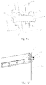
- FIG. 5 is a schematic side view of a compensation element according to another embodiment of the present invention, wherein a panel body 2 is partially described in an area of one of the ends.
- the compensation element 8 may be a movable part drawable and rotatable with respect to the end of the panel body 2 , wherein a length difference may be compensated by means of drawing, and an angle difference may be compensated by means of rotation.
- the panel body 2 may be constructed in a U-shape in the area of the end.
- the two legs 33 of the U-shape may respectively have a groove extending in a length direction of the panel body 2 (not shown), in which a pivot 34 of the compensation element 8 is received respectively.
- the pivot is arranged on one end side of a sheet 35 of the compensation element 8 , and the compensation element 8 is connectable to the fitting 3 on the other opposite end side 36 of the sheet 35 .
- this may be realized by means of a bolted connection.
- the compensation element 8 is partially drawn out from the U-shape of the panel body 2 , and the compensation element 8 rotates about the pivot 34 , so that the end side 36 is attached against the surface of the fitting 3 in a planar manner.
- FIG. 6 is a schematic side view of a compensation element according to another embodiment of the present invention.
- the compensation element 8 may be a movable member including a first portion 37 drawable with respect to one of the ends of the panel body 2 and a second portion 39 that is hinged to the first portion, wherein the hinge 38 that connects the first portion 37 and the second portion 39 is indicated by a broken line in FIG. 6 , and the first portion 37 and the second portion 39 are coplanarly depicted in FIG. 6 .
- the second portion 39 is connectable to the fitting 3 , for example by means of a bolted connection and thus the second portion includes a mounting hole 40 for a bolt.
- the panel body 2 may have grooves in the area of the respective end, for guiding the first portion 37 linearly in translation.
- the first portion 37 is in the same plane as the panel body 2 .
- the first portion 37 of the compensation element 8 is completely received in the area of the respective end of the panel body 2
- the second portion 39 of the compensation element 8 is substantially perpendicular with respect to the first portion 37
- the mounting hole 40 is aligned with one of the mounting holes 4 of the fitting 3 .
- the compensation element 8 is drawn out partially from the respective end portion of the panel body 2 , and the second portion 39 rotates with respect to the first portion 37 such that the second portion 39 is attached against the surface of the fitting 3 in a planar manner.
Landscapes
- Engineering & Computer Science (AREA)
- Computer Networks & Wireless Communication (AREA)
- Structure Of Telephone Exchanges (AREA)
- Casings For Electric Apparatus (AREA)
Abstract
Description
Claims (21)
Applications Claiming Priority (2)
| Application Number | Priority Date | Filing Date | Title |
|---|---|---|---|
| CN201911153321.4A CN112839265A (en) | 2019-11-22 | 2019-11-22 | Communication Patch Panels and Communication Rack Systems |
| CN201911153321.4 | 2019-11-22 |
Publications (2)
| Publication Number | Publication Date |
|---|---|
| US20210160592A1 US20210160592A1 (en) | 2021-05-27 |
| US11509975B2 true US11509975B2 (en) | 2022-11-22 |
Family
ID=75921609
Family Applications (1)
| Application Number | Title | Priority Date | Filing Date |
|---|---|---|---|
| US16/952,465 Active US11509975B2 (en) | 2019-11-22 | 2020-11-19 | Communication patch panel and communication rack system |
Country Status (2)
| Country | Link |
|---|---|
| US (1) | US11509975B2 (en) |
| CN (1) | CN112839265A (en) |
Citations (10)
| Publication number | Priority date | Publication date | Assignee | Title |
|---|---|---|---|---|
| US5129842A (en) * | 1991-04-08 | 1992-07-14 | Digital Equipment Corporation | Modular patch panel |
| US5975962A (en) * | 1998-02-20 | 1999-11-02 | Laukonis; Robert | Network shelf system |
| US6086415A (en) * | 1998-10-29 | 2000-07-11 | Hubbell Incorporated | High density modular patch panel |
| US20040056155A1 (en) * | 2002-09-25 | 2004-03-25 | King Slide Works Co., Ltd. | Adjustable bracket device of a cable management arm for furniture |
| US20080176445A1 (en) | 2007-01-24 | 2008-07-24 | Pinchas Shifris | Patch panel with a variable angle |
| US7534135B2 (en) | 1998-06-05 | 2009-05-19 | Adc Telecommunications, Inc. | Telecommunications patch panel with angled connector modules |
| US20090305554A1 (en) | 2006-06-29 | 2009-12-10 | Siano Frank S | Adjustable Patch Panel and Methods of Using Same |
| JP2012104650A (en) * | 2010-11-10 | 2012-05-31 | Hitachi Systems Ltd | Patch panel fixing device |
| US9720195B2 (en) * | 2010-04-30 | 2017-08-01 | Corning Optical Communications LLC | Apparatuses and related components and methods for attachment and release of fiber optic housings to and from an equipment rack |
| US9775260B1 (en) * | 2015-03-23 | 2017-09-26 | Adva Optical Networking Se | Brackets for use with three rack mount systems |
Family Cites Families (4)
| Publication number | Priority date | Publication date | Assignee | Title |
|---|---|---|---|---|
| TW232757B (en) * | 1994-01-21 | 1994-10-21 | Adc Telecommunications Inc | High-density fiber distribution frame |
| US6424781B1 (en) * | 1999-03-01 | 2002-07-23 | Adc Telecommunications, Inc. | Optical fiber distribution frame with pivoting connector panels |
| US9348104B2 (en) * | 2012-12-11 | 2016-05-24 | CommScope Connectivity Belgium BVBA | Universal cable management system for telecommunications rack |
| CN110166852B (en) * | 2019-06-21 | 2024-02-02 | 上海天诚通信技术股份有限公司 | General distribution frame with support column structure |
-
2019
- 2019-11-22 CN CN201911153321.4A patent/CN112839265A/en active Pending
-
2020
- 2020-11-19 US US16/952,465 patent/US11509975B2/en active Active
Patent Citations (10)
| Publication number | Priority date | Publication date | Assignee | Title |
|---|---|---|---|---|
| US5129842A (en) * | 1991-04-08 | 1992-07-14 | Digital Equipment Corporation | Modular patch panel |
| US5975962A (en) * | 1998-02-20 | 1999-11-02 | Laukonis; Robert | Network shelf system |
| US7534135B2 (en) | 1998-06-05 | 2009-05-19 | Adc Telecommunications, Inc. | Telecommunications patch panel with angled connector modules |
| US6086415A (en) * | 1998-10-29 | 2000-07-11 | Hubbell Incorporated | High density modular patch panel |
| US20040056155A1 (en) * | 2002-09-25 | 2004-03-25 | King Slide Works Co., Ltd. | Adjustable bracket device of a cable management arm for furniture |
| US20090305554A1 (en) | 2006-06-29 | 2009-12-10 | Siano Frank S | Adjustable Patch Panel and Methods of Using Same |
| US20080176445A1 (en) | 2007-01-24 | 2008-07-24 | Pinchas Shifris | Patch panel with a variable angle |
| US9720195B2 (en) * | 2010-04-30 | 2017-08-01 | Corning Optical Communications LLC | Apparatuses and related components and methods for attachment and release of fiber optic housings to and from an equipment rack |
| JP2012104650A (en) * | 2010-11-10 | 2012-05-31 | Hitachi Systems Ltd | Patch panel fixing device |
| US9775260B1 (en) * | 2015-03-23 | 2017-09-26 | Adva Optical Networking Se | Brackets for use with three rack mount systems |
Also Published As
| Publication number | Publication date |
|---|---|
| US20210160592A1 (en) | 2021-05-27 |
| CN112839265A (en) | 2021-05-25 |
Similar Documents
| Publication | Publication Date | Title |
|---|---|---|
| DE60131184T2 (en) | HIGH DENSITY FIBER DISTRIBUTION MOUNTING SYSTEM | |
| US7300308B2 (en) | Patch panel | |
| US20060194470A1 (en) | Stair-stepped angled patch panel | |
| US9232676B2 (en) | Spacers for a cable backplane system | |
| US7142763B2 (en) | Optical waveguide distribution cabinet | |
| DE69518803T2 (en) | Optical fiber guidance | |
| DE60126273T2 (en) | OPTICAL ARRANGEMENT | |
| US20050111810A1 (en) | Connector housing for a communication network | |
| US11439036B2 (en) | Slide rail assembly | |
| DE102009058118A1 (en) | Junction box for solar modules | |
| US20090090534A1 (en) | Cable management patch panel system with vertical ducting | |
| US20160276790A1 (en) | Cable connector mounts for connector bricks of a cable communication system | |
| US9326417B2 (en) | Cable backplane system having mounting blocks | |
| US11509975B2 (en) | Communication patch panel and communication rack system | |
| DE102015108528B4 (en) | Distribution cabinet | |
| DE19860440C1 (en) | Receptacle | |
| EP3916449B1 (en) | Splice module stack with improved cable guide | |
| US20080026613A1 (en) | Conductor Connection | |
| WO2011091914A1 (en) | Profiled support element for a support arm system | |
| JP5064175B2 (en) | Desk equipment | |
| EP2348591B1 (en) | Support arm | |
| US20250164729A1 (en) | Patch Field Mounting Bracket System | |
| DE102007016601B4 (en) | Plug-in modular personal computer construction | |
| EP4498141B1 (en) | Rail assembly, beam assembly and fiber optic distribution system | |
| DE202004012696U1 (en) | Distribution cabinet for light wave guide communications cables, has a swiveling frame on a base stand for accepting communications cables |
Legal Events
| Date | Code | Title | Description |
|---|---|---|---|
| FEPP | Fee payment procedure |
Free format text: ENTITY STATUS SET TO UNDISCOUNTED (ORIGINAL EVENT CODE: BIG.); ENTITY STATUS OF PATENT OWNER: LARGE ENTITY |
|
| STPP | Information on status: patent application and granting procedure in general |
Free format text: APPLICATION DISPATCHED FROM PREEXAM, NOT YET DOCKETED |
|
| AS | Assignment |
Owner name: COMMSCOPE TECHNOLOGIES LLC, NORTH CAROLINA Free format text: ASSIGNMENT OF ASSIGNORS INTEREST;ASSIGNORS:LIU, ZHIHUI;THIJS, DANNY GHISLAIN;WU, WENYONG;AND OTHERS;SIGNING DATES FROM 20210217 TO 20210218;REEL/FRAME:055348/0146 |
|
| STPP | Information on status: patent application and granting procedure in general |
Free format text: DOCKETED NEW CASE - READY FOR EXAMINATION |
|
| AS | Assignment |
Owner name: JPMORGAN CHASE BANK, N.A., NEW YORK Free format text: ABL SECURITY AGREEMENT;ASSIGNORS:ARRIS ENTERPRISES LLC;COMMSCOPE TECHNOLOGIES LLC;COMMSCOPE, INC. OF NORTH CAROLINA;REEL/FRAME:058843/0712 Effective date: 20211112 Owner name: JPMORGAN CHASE BANK, N.A., NEW YORK Free format text: TERM LOAN SECURITY AGREEMENT;ASSIGNORS:ARRIS ENTERPRISES LLC;COMMSCOPE TECHNOLOGIES LLC;COMMSCOPE, INC. OF NORTH CAROLINA;REEL/FRAME:058875/0449 Effective date: 20211112 |
|
| AS | Assignment |
Owner name: WILMINGTON TRUST, DELAWARE Free format text: SECURITY INTEREST;ASSIGNORS:ARRIS SOLUTIONS, INC.;ARRIS ENTERPRISES LLC;COMMSCOPE TECHNOLOGIES LLC;AND OTHERS;REEL/FRAME:060752/0001 Effective date: 20211115 |
|
| STPP | Information on status: patent application and granting procedure in general |
Free format text: NON FINAL ACTION MAILED |
|
| STPP | Information on status: patent application and granting procedure in general |
Free format text: RESPONSE TO NON-FINAL OFFICE ACTION ENTERED AND FORWARDED TO EXAMINER |
|
| STPP | Information on status: patent application and granting procedure in general |
Free format text: FINAL REJECTION MAILED |
|
| STPP | Information on status: patent application and granting procedure in general |
Free format text: NOTICE OF ALLOWANCE MAILED -- APPLICATION RECEIVED IN OFFICE OF PUBLICATIONS |
|
| STCF | Information on status: patent grant |
Free format text: PATENTED CASE |
|
| CC | Certificate of correction | ||
| AS | Assignment |
Owner name: APOLLO ADMINISTRATIVE AGENCY LLC, NEW YORK Free format text: SECURITY INTEREST;ASSIGNORS:ARRIS ENTERPRISES LLC;COMMSCOPE TECHNOLOGIES LLC;COMMSCOPE INC., OF NORTH CAROLINA;AND OTHERS;REEL/FRAME:069889/0114 Effective date: 20241217 |
|
| AS | Assignment |
Owner name: COMMSCOPE TECHNOLOGIES LLC, NORTH CAROLINA Free format text: RELEASE OF SECURITY INTEREST AT REEL/FRAME 058875/0449;ASSIGNOR:JPMORGAN CHASE BANK, N.A., AS COLLATERAL AGENT;REEL/FRAME:069743/0057 Effective date: 20241217 Owner name: COMMSCOPE, INC. OF NORTH CAROLINA, NORTH CAROLINA Free format text: RELEASE OF SECURITY INTEREST AT REEL/FRAME 058875/0449;ASSIGNOR:JPMORGAN CHASE BANK, N.A., AS COLLATERAL AGENT;REEL/FRAME:069743/0057 Effective date: 20241217 Owner name: ARRIS ENTERPRISES LLC (F/K/A ARRIS ENTERPRISES, INC.), NORTH CAROLINA Free format text: RELEASE OF SECURITY INTEREST AT REEL/FRAME 058875/0449;ASSIGNOR:JPMORGAN CHASE BANK, N.A., AS COLLATERAL AGENT;REEL/FRAME:069743/0057 Effective date: 20241217 |