US11504682B2 - Mixer base assembly for mixing vessels and method of use - Google Patents
Mixer base assembly for mixing vessels and method of use Download PDFInfo
- Publication number
- US11504682B2 US11504682B2 US16/724,539 US201916724539A US11504682B2 US 11504682 B2 US11504682 B2 US 11504682B2 US 201916724539 A US201916724539 A US 201916724539A US 11504682 B2 US11504682 B2 US 11504682B2
- Authority
- US
- United States
- Prior art keywords
- port
- base assembly
- side wall
- mixing chamber
- fluid
- Prior art date
- Legal status (The legal status is an assumption and is not a legal conclusion. Google has not performed a legal analysis and makes no representation as to the accuracy of the status listed.)
- Active, expires
Links
Images


Classifications
-
- B—PERFORMING OPERATIONS; TRANSPORTING
- B01—PHYSICAL OR CHEMICAL PROCESSES OR APPARATUS IN GENERAL
- B01F—MIXING, e.g. DISSOLVING, EMULSIFYING OR DISPERSING
- B01F33/00—Other mixers; Mixing plants; Combinations of mixers
- B01F33/45—Magnetic mixers; Mixers with magnetically driven stirrers
- B01F33/453—Magnetic mixers; Mixers with magnetically driven stirrers using supported or suspended stirring elements
- B01F33/4532—Magnetic mixers; Mixers with magnetically driven stirrers using supported or suspended stirring elements using a bearing, tube, opening or gap for internally supporting the stirring element
-
- B—PERFORMING OPERATIONS; TRANSPORTING
- B01—PHYSICAL OR CHEMICAL PROCESSES OR APPARATUS IN GENERAL
- B01F—MIXING, e.g. DISSOLVING, EMULSIFYING OR DISPERSING
- B01F33/00—Other mixers; Mixing plants; Combinations of mixers
- B01F33/45—Magnetic mixers; Mixers with magnetically driven stirrers
- B01F33/453—Magnetic mixers; Mixers with magnetically driven stirrers using supported or suspended stirring elements
- B01F33/4535—Magnetic mixers; Mixers with magnetically driven stirrers using supported or suspended stirring elements using a stud for supporting the stirring element
-
- B—PERFORMING OPERATIONS; TRANSPORTING
- B01—PHYSICAL OR CHEMICAL PROCESSES OR APPARATUS IN GENERAL
- B01F—MIXING, e.g. DISSOLVING, EMULSIFYING OR DISPERSING
- B01F35/00—Accessories for mixers; Auxiliary operations or auxiliary devices; Parts or details of general application
- B01F35/40—Mounting or supporting mixing devices or receptacles; Clamping or holding arrangements therefor
-
- B—PERFORMING OPERATIONS; TRANSPORTING
- B01—PHYSICAL OR CHEMICAL PROCESSES OR APPARATUS IN GENERAL
- B01F—MIXING, e.g. DISSOLVING, EMULSIFYING OR DISPERSING
- B01F27/00—Mixers with rotary stirring devices in fixed receptacles; Kneaders
- B01F27/80—Mixers with rotary stirring devices in fixed receptacles; Kneaders with stirrers rotating about a substantially vertical axis
- B01F27/808—Mixers with rotary stirring devices in fixed receptacles; Kneaders with stirrers rotating about a substantially vertical axis with stirrers driven from the bottom of the receptacle
-
- B—PERFORMING OPERATIONS; TRANSPORTING
- B01—PHYSICAL OR CHEMICAL PROCESSES OR APPARATUS IN GENERAL
- B01F—MIXING, e.g. DISSOLVING, EMULSIFYING OR DISPERSING
- B01F33/00—Other mixers; Mixing plants; Combinations of mixers
- B01F33/45—Magnetic mixers; Mixers with magnetically driven stirrers
-
- B—PERFORMING OPERATIONS; TRANSPORTING
- B01—PHYSICAL OR CHEMICAL PROCESSES OR APPARATUS IN GENERAL
- B01F—MIXING, e.g. DISSOLVING, EMULSIFYING OR DISPERSING
- B01F33/00—Other mixers; Mixing plants; Combinations of mixers
- B01F33/45—Magnetic mixers; Mixers with magnetically driven stirrers
- B01F33/452—Magnetic mixers; Mixers with magnetically driven stirrers using independent floating stirring elements
-
- B—PERFORMING OPERATIONS; TRANSPORTING
- B01—PHYSICAL OR CHEMICAL PROCESSES OR APPARATUS IN GENERAL
- B01F—MIXING, e.g. DISSOLVING, EMULSIFYING OR DISPERSING
- B01F33/00—Other mixers; Mixing plants; Combinations of mixers
- B01F33/86—Mixing heads comprising a driven stirrer
-
- B—PERFORMING OPERATIONS; TRANSPORTING
- B01—PHYSICAL OR CHEMICAL PROCESSES OR APPARATUS IN GENERAL
- B01F—MIXING, e.g. DISSOLVING, EMULSIFYING OR DISPERSING
- B01F35/00—Accessories for mixers; Auxiliary operations or auxiliary devices; Parts or details of general application
- B01F35/181—Preventing generation of dust or dirt; Sieves; Filters
-
- B—PERFORMING OPERATIONS; TRANSPORTING
- B01—PHYSICAL OR CHEMICAL PROCESSES OR APPARATUS IN GENERAL
- B01F—MIXING, e.g. DISSOLVING, EMULSIFYING OR DISPERSING
- B01F35/00—Accessories for mixers; Auxiliary operations or auxiliary devices; Parts or details of general application
- B01F35/20—Measuring; Control or regulation
- B01F35/21—Measuring
- B01F35/213—Measuring of the properties of the mixtures, e.g. temperature, density or colour
-
- B—PERFORMING OPERATIONS; TRANSPORTING
- B01—PHYSICAL OR CHEMICAL PROCESSES OR APPARATUS IN GENERAL
- B01F—MIXING, e.g. DISSOLVING, EMULSIFYING OR DISPERSING
- B01F35/00—Accessories for mixers; Auxiliary operations or auxiliary devices; Parts or details of general application
- B01F35/20—Measuring; Control or regulation
- B01F35/21—Measuring
- B01F35/2132—Concentration, pH, pOH, p(ION) or oxygen-demand
-
- B—PERFORMING OPERATIONS; TRANSPORTING
- B01—PHYSICAL OR CHEMICAL PROCESSES OR APPARATUS IN GENERAL
- B01F—MIXING, e.g. DISSOLVING, EMULSIFYING OR DISPERSING
- B01F35/00—Accessories for mixers; Auxiliary operations or auxiliary devices; Parts or details of general application
- B01F35/20—Measuring; Control or regulation
- B01F35/21—Measuring
- B01F35/2133—Electrical conductivity or dielectric constant of the mixture
-
- B—PERFORMING OPERATIONS; TRANSPORTING
- B01—PHYSICAL OR CHEMICAL PROCESSES OR APPARATUS IN GENERAL
- B01F—MIXING, e.g. DISSOLVING, EMULSIFYING OR DISPERSING
- B01F35/00—Accessories for mixers; Auxiliary operations or auxiliary devices; Parts or details of general application
- B01F35/30—Driving arrangements; Transmissions; Couplings; Brakes
-
- B—PERFORMING OPERATIONS; TRANSPORTING
- B01—PHYSICAL OR CHEMICAL PROCESSES OR APPARATUS IN GENERAL
- B01F—MIXING, e.g. DISSOLVING, EMULSIFYING OR DISPERSING
- B01F35/00—Accessories for mixers; Auxiliary operations or auxiliary devices; Parts or details of general application
- B01F35/50—Mixing receptacles
- B01F35/51—Mixing receptacles characterised by their material
-
- B—PERFORMING OPERATIONS; TRANSPORTING
- B01—PHYSICAL OR CHEMICAL PROCESSES OR APPARATUS IN GENERAL
- B01F—MIXING, e.g. DISSOLVING, EMULSIFYING OR DISPERSING
- B01F35/00—Accessories for mixers; Auxiliary operations or auxiliary devices; Parts or details of general application
- B01F35/50—Mixing receptacles
- B01F35/513—Flexible receptacles, e.g. bags supported by rigid containers
-
- B—PERFORMING OPERATIONS; TRANSPORTING
- B01—PHYSICAL OR CHEMICAL PROCESSES OR APPARATUS IN GENERAL
- B01F—MIXING, e.g. DISSOLVING, EMULSIFYING OR DISPERSING
- B01F35/00—Accessories for mixers; Auxiliary operations or auxiliary devices; Parts or details of general application
- B01F35/50—Mixing receptacles
- B01F35/53—Mixing receptacles characterised by the configuration of the interior, e.g. baffles for facilitating the mixing of components
- B01F35/531—Mixing receptacles characterised by the configuration of the interior, e.g. baffles for facilitating the mixing of components with baffles, plates or bars on the wall or the bottom
-
- B—PERFORMING OPERATIONS; TRANSPORTING
- B01—PHYSICAL OR CHEMICAL PROCESSES OR APPARATUS IN GENERAL
- B01F—MIXING, e.g. DISSOLVING, EMULSIFYING OR DISPERSING
- B01F35/00—Accessories for mixers; Auxiliary operations or auxiliary devices; Parts or details of general application
- B01F35/55—Baffles; Flow breakers
-
- B—PERFORMING OPERATIONS; TRANSPORTING
- B01—PHYSICAL OR CHEMICAL PROCESSES OR APPARATUS IN GENERAL
- B01F—MIXING, e.g. DISSOLVING, EMULSIFYING OR DISPERSING
- B01F35/00—Accessories for mixers; Auxiliary operations or auxiliary devices; Parts or details of general application
- B01F35/71—Feed mechanisms
Definitions
- Mixing vessels are mounted to mixer bases for use. However, different mixing vessels have different shapes and/or configurations and can require specialized mixer bases for use.
- the present invention provides for ameliorating at least some of the disadvantages of the prior art.
- An embodiment of the invention provides a mixer base assembly comprising (a) a body having (i) an upper end including a mating face for mixing vessel connection; (ii) a lower end including a cavity; (iii) a plurality of side walls; (iv) an inlet port arranged in a side wall; (v) an outlet port arranged in a side wall; (vi) a sampling port arranged in a side wall; (vii) at least one probe port arranged in a side wall; and, (viii) a fluid mixing chamber including a baffle, the fluid mixing chamber having a bottom wall; (b) an impeller seat arranged in the cavity in the lower end of the body; and, (c) a levitating magnetic impeller arranged in the impeller seat, the impeller comprising a magnet, a base, and at least two blades, wherein the at least two blades extend above the bottom wall of the fluid mixing chamber into the fluid mixing chamber.
- a method for mixing fluid comprises connecting a mixing vessel to a mixer base assembly comprising (a) a body having (i) an upper end including a mating face for mixing vessel connection; (ii) a lower end including a cavity; (iii) a plurality of side walls; (iv) an inlet port arranged in a side wall; (v) an outlet port arranged in a side wall; (vi) a sampling port arranged in a side wall; (vii) at least one probe port arranged in a side wall; and, (viii) a fluid mixing chamber including a baffle, the fluid mixing chamber having a bottom wall; (b) an impeller seat arranged in the cavity in the lower end of the body; and, (c) a levitating magnetic impeller arranged in the impeller seat, the impeller comprising a magnet, a base, and at least two blades, wherein the at least two blades extend above the bottom wall of the fluid mixing chamber into the fluid mixing chamber; introducing fluid into the fluid mixing chamber
- FIG. 1 is an exploded top view of a mixer base assembly according to an embodiment of the invention, wherein the mixer base assembly comprises a body comprising a baffle, a fluid mixing chamber, two probe ports, a sample port, an inlet port, an outlet port, a vent inlet port, and a vent outlet port, the mixer base also comprising a levitating magnetic impeller, and an interface plate including an impeller seat, two probes, an inlet connector, an outlet connector, a vent filter, a sample port plug including a sealing gasket, a sample port nut, and fluid conduits.
- the mixer base assembly comprises a body comprising a baffle, a fluid mixing chamber, two probe ports, a sample port, an inlet port, an outlet port, a vent inlet port, and a vent outlet port, the mixer base also comprising a levitating magnetic impeller, and an interface plate including an impeller seat, two probes, an inlet connector, an outlet connector, a vent filter, a sample port plug including a sealing gasket
- FIG. 2 is a bottom view of the mixer base assembly shown in FIG. 1 .
- FIG. 3A is a top view of a portion of the mixer base assembly shown in FIG. 1 , showing an inlet port communicating with the fluid mixing chamber;
- FIG. 3B is a cross-sectional view of the mixer base assembly shown in FIG. 3A , including an arrow showing the flow path of fluid through the inlet port into the fluid mixing chamber.
- FIG. 4A is a top view of another portion of the mixer base assembly shown in FIG. 1 , showing an outlet port communicating with the fluid mixing chamber;
- FIG. 4B is a cross-sectional view of the mixer base assembly shown in FIG. 4A , including an arrow showing the flow path of fluid through from the fluid mixture chamber and the outlet port.
- FIG. 5 shows a cross-sectional view of another portion of the mixer base assembly shown in FIG. 1 , showing a downwardly sloped bottom wall of the fluid mixing chamber and the tips of two probes arranged to sense fluid parameters in the fluid mixing chamber, preferably wherein the slope toward the outlet port minimizes hold-up volume and/or helps create a taller height of fluid with a minimum volume to allow sensing of the fluid parameters.
- FIG. 5 also shows that the tips of the probes are angled downwardly into the fluid mixing chamber.
- FIG. 6 is a partial cross-sectional view of another portion of the mixer base assembly shown in FIG. 1 , showing a vent filter inlet port, a vent filter outlet port, a vent filter communicating with the vent filter outlet port, and fluid conduits.
- FIG. 7 is a top perspective view of the interface plate shown in FIG. 1 , also showing the impeller seat.
- FIG. 8 is a partial top view of the mixer base assembly shown in FIG. 1 , showing the body including the baffle, and the impeller.
- FIGS. 9A, 10A, 11A, and 12A show embodiments of the mixer base assembly connectable to a variety of mixing vessels, wherein the mixer base assembly is docked into a hardware system (shown in FIGS. 13A-13D ) containing electronics and a drive unit to rotate the impeller.
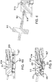
- FIG. 9A shows an embodiment of the mixer base assembly connectable to a commercially available rigid mixing vessel, including a threaded mounting ring that can be threaded to the bottom of the mixing vessel and mated (e.g., by pins or screws) to the mating face of the mixer base assembly;
- FIG. 9B shows an enlarged view of the threaded base of the mixing vessel and the mounting ring,
- FIGS. 9C and 9D show, respectively, a cross-sectional view, and a bottom perspective view, of the mounting ring.
- FIG. 10A shows an embodiment of the mixer base assembly connectable to a custom molded rigid mixing vessel
- FIG. 10B shows an enlarged view of the mounting flange at the bottom of the mixing vessel and the mating face of the mixer base assembly, wherein they can be mated together (e.g., by pins or screws, or welded)
- FIG. 10C shows a perspective bottom view of the mounting flange at the bottom of the mixing vessel.
- FIG. 11A shows an embodiment of the mixer base assembly connectable to a flexible mixing vessel (a biocontainer) arranged in a tote, including upper and lower sanitary flanges and a tri-clamp;
- FIG. 11B shows an enlarged view of the upper sanitary flange and the tri-clamp;
- FIG. 11C shows an exploded view of the upper sanitary flange, the tri-clamp, and the lower sanitary flange (that can be mated, e.g., by pins or screws, or injection molded as part of the body) to the mating face of the mixer base assembly.
- FIG. 12A shows an embodiment of the mixer base assembly connectable by an adapter to a custom vacuum formed mixing vessel having halves welded together, wherein the vessel can be rigid or flexible; also showing a mating flange connectable to the bottom of the mixing vessel and an adapter for connecting the mating flange to the mixer base assembly;
- FIG. 12B shows an enlarged view of the mating flange and adapter,
- FIG. 12C shows top perspective views of the mating flange, adapter, and a sealing ring providing a seal between the adapter and the mating face of the mixer base assembly;
- FIG. 12D shows a bottom perspective view of the sealing ring.
- FIG. 13A shows an illustrative hardware system
- FIG. 13B shows a front partially disassembled view of the hardware system shown in FIG. 13A
- FIG. 13C shows a rear partially disassembled view of the hardware system shown in FIG. 13A
- FIG. 13D shows an internal view of the hardware system shown in FIG. 13A .
- a mixer base assembly comprising (a) a body having (i) an upper end including a mating face for mixing vessel connection; (ii) a lower end including a cavity; (iii) a plurality of side walls; (iv) an inlet port arranged in a side wall; (v) an outlet port arranged in a side wall; (vi) a sampling port arranged in a side wall; (vii) at least one probe port arranged in a side wall; and, (viii) a fluid mixing chamber including a baffle, the fluid mixing chamber having a bottom wall; (b) an impeller seat arranged in the cavity in the lower end of the body; and, (c) a levitating magnetic impeller arranged in the impeller seat, the impeller comprising a magnet, a base, and at least two blades, wherein the at least two blades extend above the bottom wall of the fluid mixing chamber into the fluid mixing chamber.
- the impeller seat is fluid tightly sealed to the bottom wall of the fluid mixing chamber.
- it can be included as part of the fluid mixing chamber (e.g., as a single, injection-molded part).
- the mixer base assembly includes two probe ports.
- the mixer base assembly further a vent inlet port and a vent outlet port, wherein the vent outlet port is arranged in a side wall of the body.
- the vent outlet port is arranged in the body of the mixing vessel.
- the bottom wall of the mixing chamber slopes downwardly toward the outlet port, and in a more preferred embodiment, the mixer base assembly further comprises at least one probe arranged in the at least one probe port, wherein a tip of the at least one probe (where the sensing element is located) is angled downwardly into the mixing chamber.
- the mixer base assembly includes two probe ports, and two probes, each arranged in a separate probe port, wherein the tip of each probe is angled downwardly into the mixing chamber.
- a method for using a mixing fluid comprises connecting a mixing vessel to a mixer base assembly comprising (a) a body having (i) an upper end including a mating face for mixing vessel connection; (ii) a lower end including a cavity; (iii) a plurality of side walls; (iv) an inlet port arranged in a side wall; (v) an outlet port arranged in a side wall; (vi) a sampling port arranged in a side wall; (vii) at least one probe port arranged in a side wall; and, (viii) a fluid mixing chamber including a baffle, the fluid mixing chamber having a bottom wall; (b) an impeller seat arranged in the cavity in the lower end of the body; and, (c) a levitating magnetic impeller arranged in the impeller seat, the impeller comprising a magnet, a base, and at least two blades, wherein the at least two blades extend above the bottom wall of the fluid mixing chamber into the fluid mixing chamber; introducing fluid into the
- Embodiments of the method can further comprise, for example, measuring or detecting a parameter of the fluid in the fluid mixing chamber (e.g., measuring the pH and/or the conductivity of the fluid) and/or sampling the fluid in the fluid mixing chamber and/or venting air from the mixer base assembly.
- a parameter of the fluid in the fluid mixing chamber e.g., measuring the pH and/or the conductivity of the fluid
- sampling the fluid in the fluid mixing chamber and/or venting air from the mixer base assembly e.g., measuring the pH and/or the conductivity of the fluid
- embodiments of the present invention provide a “clever base” that can be used with a variety of mixing vessels having different shapes and/or configurations. Homogenized mixing of a wide range of liquid volumes (e.g, about 35 ml to about 10,000 ml) and/or a liquids having wide range of viscosities (e.g., about 1 to about 25 Centipoise (cP)) can be achieved while minimizing or eliminating splashing, foaming, and/or vortexing of the liquids. Moreover, the use of a levitating magnetic impeller significantly reduces shear force, and eliminates rubbing of parts, thus reducing or eliminating particle shed that could contaminate the fluid.
- a levitating magnetic impeller significantly reduces shear force, and eliminates rubbing of parts, thus reducing or eliminating particle shed that could contaminate the fluid.
- Embodiments of the invention can be used with low volume mixing vessels, and if desired, can be connected to aseptic sampling devices (manual or automatic). If the mixing vessel does not have a vent filter, embodiments of the invention can include connection for a vent filter to maintain sterility and equilibrium of pressures within the system.
- the mixer base assembly is single-use.
- FIG. 1 is an exploded top view of an embodiment of the mixer base assembly according to the invention, wherein the mixer base assembly 500 is part of a mixing base system 1000 .
- the illustrated embodiment of the mixer base assembly 500 comprises a body 550 having an upper end 571 including a mating face 575 for mixing vessel/mixing vessel adapter connection; a lower end 572 including a cavity 557 ; a plurality of side walls ( 4 side walls 551 A, 551 B, 551 C, 551 D are illustrated; an inlet port 501 (shown in more detail in FIG.
- a side wall 551 A also showing an inlet port fitting 501 A arranged in the inlet port
- an outlet port 502 (having an entrance 502 ′ and an exit 502 ′′) (the inlet and outlet ports can be separate components installed in the body or included in the body as a single injection molded part) passing through a different side wall 551 C (also showing an outlet port fitting 502 A arranged in the outlet port 502 as it passes (exits at 502 ′′) through the side wall); a sampling port 507 arranged in a side wall 551 D (the illustrated port having external threads); at least one probe port arranged in a side wall 551 C (two probe ports 518 , 519 are illustrated, in some embodiments, the ports having internal threads, and probe adapters 818 B and 819 B have external threads, as well as o-rings (o-rings not shown)); and, a fluid mixing chamber 530 including a baffle (or vortex breaker) 525 , the fluid mixing
- fluid is preferably directed via the inlet port 501 to a lower part of the fluid mixing chamber to minimize splashing upon entry, and as shown in FIGS. 4A-4B , the outlet port 502 is positioned at a low point in the bottom wall and passes through the side wall to aid in full draining of the fluid mixture chamber.
- the mixer base assembly 500 comprises a baffle (or vortex breaker) 525 in the fluid mixing chamber 530 which is advantageous for minimizing or eliminating splashing, foaming, and/or vortexing of the liquids.
- the mixer base assembly can further comprise a vent inlet port 511 (also showing a vent inlet port fitting 511 A arranged in the vent inlet port) and a vent outlet port 512 (also showing a vent outlet port fitting 512 A arranged in the vent outlet port), wherein the vent outlet port is arranged in a side wall of the body 551 A, and the vent port is in communication (e.g., via a conduit 924 ) with a vent filter 912 .
- vent inlet port 511 also showing a vent inlet port fitting 511 A arranged in the vent inlet port
- a vent outlet port 512 also showing a vent outlet port fitting 512 A arranged in the vent outlet port
- the vent outlet port is arranged in a side wall of the body 551 A
- the vent port is in communication (e.g., via a conduit 924 ) with a vent filter 912 .
- vent filters 912 are known in the art and are commercially available.
- embodiments of the mixing base system 1000 or the mixer base assembly can include a sampling arrangement 700 comprising a sample port plug 707 and sample port nut 707 A, wherein the sample port plug 707 can be arranged in the sampling port 507 .
- the sampling arrangement is for use with a threaded connection such as, for example, a DN 25 threaded connection.
- an autosampling system can be installed through the sampling port 507 and/or manual sampling can be carried out through outlet port exit 502 ′′.
- samples can be taken offline to measure parameters that the probes are not reading or to confirm a probe reading or to calibrate a sensor.
- embodiments of the mixing base system 1000 or the mixer base assembly can include a connector system 900 comprising an inlet connector 201 and an outlet connector 202 , such as aseptic connectors.
- a connector system 900 comprising an inlet connector 201 and an outlet connector 202 , such as aseptic connectors.
- aseptic connectors are commercially available, from, for example, Pall Corporation (Port Washington, N.Y., e.g., KLEENPAK® PRESTO); Cole-Parmer (Vernon Hills, Ill.); and Eldon James (Denver, Colo.).
- Embodiments of the mixing base system or the mixer base assembly further comprise at least one probe 800 , typically, two probes 818 , 819 (in some embodiments probe adapters 818 B and 819 B are used to connect the probes to the probe ports), wherein FIG. 5 also shows the tips of two probes 818 A, 819 A arranged to sense fluid parameters of fluid in the fluid mixing chamber, preferably wherein the slope toward the outlet port minimizes hold-up volume (sometimes referred to as “carry-over volume”) and/or helps create a taller height of fluid with a minimum volume to allow sensing of the fluid parameters.
- the Figure also shows that the tips of the probes are angled downwardly into the fluid mixing chamber. Advantageously, this allows positioning the tips as low as possible, and certain probes need to be positioned a few degrees above horizontal to operate correctly.
- probes are suitable for use in embodiments of the invention, and are commercially available. Suitable probes include, for example, pH probes, conductivity probes, temperature sensors, dissolved oxygen probes, and cell counters.
- the body can be fabricated from any suitable rigid impervious material, including any impervious thermoplastic material, which is compatible with the fluid being processed.
- the housing can be fabricated from a metal, such as stainless steel, or from a polymer.
- the body is injection molded.
- the adapter plate is preferably plastic, and cannot be a magnetic material.
- the mixer base assembly is connectable to a variety of mixing vessels (e.g., as shown in FIGS. 9A, 10A, 11A, and 12A ).
- FIG. 9A shows an embodiment of the mixer base assembly connectable to a commercially available rigid mixing vessel 1500 A having threads 1501 at the bottom, allowing connection with a threaded mounting ring 1502 (having threads 1502 A) that can be threaded to the bottom of the mixing vessel and mated (e.g., by pins or screws) to the mating face of the mixer base assembly;
- FIG. 9B shows an enlarged view of the threaded base of the mixing vessel and the mounting ring
- FIGS. 9C and 9D show, respectively, a cross-sectional view, and a bottom perspective view, of the mounting ring 1502 .
- FIG. 10A shows an embodiment of the mixer base assembly connectable to a custom molded rigid mixing vessel 1500 B having a base 1510 and a mounting flange 1511 ;
- FIG. 10B shows an enlarged view of the mounting flange 1511 at the bottom of the mixing vessel and the mating face of the mixer base assembly, wherein they can be mated together (e.g., by pins or screws);
- FIG. 10C shows a perspective bottom view of the mounting flange 1511 at the bottom of the mixing vessel.
- FIG. 11A shows an embodiment of the mixer base assembly connectable to a custom formed flexible mixing vessel (a biocontainer) 1500 C arranged in a tote 1507 , including a clamping arrangement 1525 comprising upper and lower sanitary flanges 1526 A, 1526 B, and a tri-clamp 1527 ;
- FIG. 11B shows an enlarged view of the upper sanitary flange 1526 A and the tri-clamp 1527 ;
- FIG. 11C shows an exploded view of the upper sanitary flange 1526 A, the tri-clamp 1527 , and the lower sanitary flange 1526 B (that can be mated, e.g., by pins or screws) to the mating face of the mixer base assembly.
- FIG. 12A shows an embodiment of the mixer base assembly connectable by an adapter to a custom vacuum formed mixing vessel 1500 D having halves welded 1517 A, 1517 B together, wherein the vessel can be rigid or flexible; also showing a mating flange 1518 connectable to the bottom of the mixing vessel and an adapter 1519 for connecting the mating flange to the mixer base assembly;
- FIG. 12B shows an enlarged view of the mating flange 1518 and adapter 1519
- FIG. 12C shows top perspective views of the mating flange 1518 , adapter 1519 , and a sealing ring 1521 providing a seal between the adapter and the mating face of the mixer base assembly;
- FIG. 12D shows a bottom perspective view of the sealing ring 1521 .
- Drive systems include a motor, an input/output (TO) module, a power supply, fans, wiring and connectors, and, optionally, a weighing system, arranged in a housing.
- TO input/output
- FIGS. 13A-13D show an illustrative drive system 2500 comprising a motor 2000 (shown in FIGS. 13B and 13C ); an I/O module 2100 , DC-DC converters 2150 A, 2150 B and terminal blocks 2155 (mounted to a rail 2160 ), inlet and outlet fans 2175 A, 2175 B ( FIG. 13D ), a power receptacle 2190 ; a weighing system 2200 (shown including a weighing system cover 2201 and a weighing system load cell 2202 ( FIGS. 13B and 13C ), as well as a weighing system display 2203 and weighing system connector 2204 ( FIG. 13D ).
- a weighing system 2200 shown including a weighing system cover 2201 and a weighing system load cell 2202 ( FIGS. 13B and 13C ), as well as a weighing system display 2203 and weighing system connector 2204 ( FIG. 13D ).
- the illustrated housing 2300 includes a front cover 2301 , a rear cover 2302 , a top cover/mixer base support 2303 , and a chassis 2304 .
- FIG. 13C shows a top cover gasket 2401 is mounted on top of the top cover/mixer base support 2303 , and a mixer base assembly gasket 2402 is mounted on top of the motor 2000 .
- motors for magnetically levitating and spinning the impellers are known in the art.
- Commercially available motors include those available from Pall Corporation (Port Washington, N.Y.; e.g., LEVMIXER® SYSTEM) and Levitronix GmbH (Zurich, Switzerland).
- the mating face of the mixer base assembly can be adapted for connection to a variety of size, shape, and/or type of mixing vessels, and the bottom surface of the interface plate can be adapted for docking to a variety of drive systems.
- components and/or processes such as screws, pins, bolts, mounting rings, adapters, o-rings (with or without grooves or channels in the mating face), sanitary gaskets, and/or ultrasonic welding can be used for efficient connection.
- FIGS. 9B-9D, 10B-10C, 11B-11C, and 12B-12D show exemplary components and processes for connection
- FIG. 13C shows exemplary components for docking.
- This example demonstrates the quick (less than 60 seconds) homogenous mixing time and low carry-over volume (less than 20 mL) when using a mixer base assembly according to an embodiment of the invention with a variety of mixing vessels and fluid viscosities.
- FIG. 1 An embodiment of a mixer base assembly as generally shown in FIG. 1 is connected to mixing vessels and drive units as generally shown in FIGS. 9A, 10A, 11A, and 12B .
- the fluid volume is 100 mL, and the impeller speed is 700 rpm.
- the fluid viscosity is 1 cP, in the other set of experiments, the fluid viscosity if 25 cP.
- the homogenous mixing time is conducted via additions of acids and bases, and time recorded to stability of pH, defined as a 10 second period of time with a pH change of ⁇ 0.1.
- the mixing time for the acid is 14 seconds
- the mixing time for the base is 13 seconds.
- the mixing time for the acid is 24 seconds
- the mixing time for the base is 31 seconds.
- the carry-over volume for the mixing vessel shown in FIG. 9A is 7 mL; for FIG. 10A , 11 mL; for FIG. 11A , 4 mL, and for FIG. 12A , 15 mL.
- This example demonstrates the quick (less than 60 seconds) homogenous mixing time and low carry-over volume (less than 20 mL) when using a mixer base assembly according to an embodiment of the invention with a variety of mixing vessels and fluid viscosities.
- Example 2 This example is similar to Example 1, with the exception that the fluid volume is 10,000 mL (100:1 turndown ratio), and the impeller speed is 5000 rpm.
- the fluid viscosity is 1 cP, in the other set of experiments, the fluid viscosity if 25 cP.
- the mixing time for the acid for the mixing vessel shown in FIG. 9A is 20 seconds, for FIG. 10A is 35 seconds, for FIG. 11A is 9 seconds, and for FIG. 12A is 29 seconds.
- the mixing time for the base for each of these mixing vessels is 31 seconds, 44 seconds, 45 seconds, and 34 seconds, respectively.
- the mixing time for the acid for the mixing vessel shown in FIG. 9A is 33 seconds, for FIG. 10A is 22 seconds, for FIG. 11A is 39 seconds, and for FIG. 12A is 32 seconds.
- the mixing time for the base for the mixing vessel shown in FIG. 9A is not stable after 1197 seconds (it is believed the shape and footprint of the vessel does not allow good mixing at high viscosity); for FIG. 10A is 35 seconds, for FIG. 11A is 34 seconds, and for FIG. 12A is 34 seconds.
- the carry-over volume for the mixing vessel shown in FIG. 9A is 7 mL; for FIG. 10A , 11 mL; for FIG. 11A , 4 mL, and for FIG. 12A , 15 mL.
Landscapes
- Chemical & Material Sciences (AREA)
- Chemical Kinetics & Catalysis (AREA)
- Mixers With Rotating Receptacles And Mixers With Vibration Mechanisms (AREA)
- Mixers Of The Rotary Stirring Type (AREA)
- Accessories For Mixers (AREA)
Abstract
Description
Claims (21)
Priority Applications (11)
| Application Number | Priority Date | Filing Date | Title |
|---|---|---|---|
| US16/724,539 US11504682B2 (en) | 2019-12-23 | 2019-12-23 | Mixer base assembly for mixing vessels and method of use |
| FIEP20199155.1T FI3842135T3 (en) | 2019-12-23 | 2020-09-30 | Mixer base assembly for mixing vessels and method of operation |
| EP20199155.1A EP3842135B9 (en) | 2019-12-23 | 2020-09-30 | Mixer base assembly for mixing vessels and method of use |
| DK20199155.1T DK3842135T3 (en) | 2019-12-23 | 2020-09-30 | MIXER BASE DEVICE FOR MIXING CONTAINERS AND METHOD OF USE |
| JP2020167106A JP7095204B2 (en) | 2019-12-23 | 2020-10-01 | Mixer-based assembly and usage for mixing vessels |
| SG10202009863WA SG10202009863WA (en) | 2019-12-23 | 2020-10-05 | Mixer base assembly for mixing vessels and method of use |
| KR1020200149066A KR102521075B1 (en) | 2019-12-23 | 2020-11-10 | Mixer base assembly for mixing vessels and method of use |
| CN202011251665.1A CN113083110B (en) | 2019-12-23 | 2020-11-11 | Mixer base assembly for mixing vessel and method of use thereof |
| CA3099502A CA3099502C (en) | 2019-12-23 | 2020-11-17 | Mixer base assembly for mixing vessels and method of use |
| BR102020026269-6A BR102020026269B1 (en) | 2019-12-23 | 2020-12-21 | MIXER BASE SET FOR MIXING CONTAINERS AND METHOD OF USE |
| AU2020294183A AU2020294183B2 (en) | 2019-12-23 | 2020-12-22 | Mixer base assembly for mixing vessels and method of use |
Applications Claiming Priority (1)
| Application Number | Priority Date | Filing Date | Title |
|---|---|---|---|
| US16/724,539 US11504682B2 (en) | 2019-12-23 | 2019-12-23 | Mixer base assembly for mixing vessels and method of use |
Publications (2)
| Publication Number | Publication Date |
|---|---|
| US20210187456A1 US20210187456A1 (en) | 2021-06-24 |
| US11504682B2 true US11504682B2 (en) | 2022-11-22 |
Family
ID=72709032
Family Applications (1)
| Application Number | Title | Priority Date | Filing Date |
|---|---|---|---|
| US16/724,539 Active 2040-04-18 US11504682B2 (en) | 2019-12-23 | 2019-12-23 | Mixer base assembly for mixing vessels and method of use |
Country Status (11)
| Country | Link |
|---|---|
| US (1) | US11504682B2 (en) |
| EP (1) | EP3842135B9 (en) |
| JP (1) | JP7095204B2 (en) |
| KR (1) | KR102521075B1 (en) |
| CN (1) | CN113083110B (en) |
| AU (1) | AU2020294183B2 (en) |
| BR (1) | BR102020026269B1 (en) |
| CA (1) | CA3099502C (en) |
| DK (1) | DK3842135T3 (en) |
| FI (1) | FI3842135T3 (en) |
| SG (1) | SG10202009863WA (en) |
Families Citing this family (6)
| Publication number | Priority date | Publication date | Assignee | Title |
|---|---|---|---|---|
| US11565222B2 (en) | 2019-12-23 | 2023-01-31 | Pall Corporation | Mixer base assembly for mixing vessels and method of use |
| US11872562B1 (en) * | 2021-03-29 | 2024-01-16 | The United States Of America As Represented By The Secretary Of The Army | Chemical detection training container and method for use thereof |
| CN115738850B (en) * | 2022-11-14 | 2024-08-13 | 济南冠龙化工有限公司 | Plant essential oil treatment processing system |
| CN115855284B (en) * | 2023-02-20 | 2023-06-02 | 郯城县检验检测中心 | Temperature detection device with alarm structure |
| US20250303373A1 (en) * | 2024-04-02 | 2025-10-02 | Cytiva Us Llc | Small volume mixing device hardware |
| US20250303375A1 (en) * | 2024-04-02 | 2025-10-02 | Cytiva Us Llc | Small volume mixing device |
Citations (20)
| Publication number | Priority date | Publication date | Assignee | Title |
|---|---|---|---|---|
| US5882113A (en) | 1997-07-15 | 1999-03-16 | Dep Corporation | Device for homogenizing and heating a liquid or mashy substance |
| US5885113A (en) | 1995-05-11 | 1999-03-23 | Itt Manufacturing Enterprises, Inc. | Connector with retained contacts |
| JP2006122785A (en) | 2004-10-27 | 2006-05-18 | Aisin Seiki Co Ltd | Non-contact stirrer |
| WO2006120945A1 (en) | 2005-05-12 | 2006-11-16 | Ebara Corporation | Mixer and reaction apparatus |
| WO2008040568A1 (en) | 2006-10-03 | 2008-04-10 | Artelis | Mixing system including a flexible bag, specific flexible bag and locating system for the mixing system |
| KR101124220B1 (en) | 2009-11-18 | 2012-03-27 | 주식회사 세종파마텍 | Mixer for exchanging the vessel |
| US8328410B1 (en) | 2008-03-14 | 2012-12-11 | E I Du Pont De Nemours And Company | In-line multi-chamber mixer |
| CN202876683U (en) | 2012-10-09 | 2013-04-17 | 宁波天益医疗器械有限公司 | Mini-type ozone water mixer |
| CN103945928A (en) | 2011-09-16 | 2014-07-23 | 通用电气医疗集团生物科学公司 | Single-use mixing and bioreactor systems |
| CN104689737A (en) | 2013-12-03 | 2015-06-10 | 默克专利股份有限公司 | Mixing device and its use |
| US20150273414A1 (en) | 2014-03-28 | 2015-10-01 | Asepco | Magnetically Coupled Mixer with Thrust Bearing Friction Control |
| KR20170029937A (en) | 2015-09-08 | 2017-03-16 | 이기남 | Impeller for mixer and mixer including thereof |
| CN107208519A (en) | 2015-01-22 | 2017-09-26 | 天纳克汽车经营有限公司 | Exhaust after treatment system with mixer assembly |
| US20170296988A1 (en) | 2014-11-21 | 2017-10-19 | Cirkul, Inc. | Adjustable additive cartridge systems and methods |
| US10059914B2 (en) * | 2013-11-21 | 2018-08-28 | Distek, Inc. | Disposable bioreactors and methods for construction and use thereof |
| WO2018162174A1 (en) | 2017-03-06 | 2018-09-13 | Spinchem Ab | Flow-promoting device, a reactor arrangement and the use of such flow-promoting device |
| CN109312284A (en) | 2016-05-31 | 2019-02-05 | 康宁股份有限公司 | Containers and spinner flasks with reduced impeller swing for culturing cells |
| US20190168901A1 (en) | 2017-12-04 | 2019-06-06 | Ecolab Usa Inc. | Powder Material Hopper System with Offset Loading |
| WO2019180710A1 (en) | 2018-03-19 | 2019-09-26 | Mayu Water Art Ltd. | Device for circulating stored drinking water with vortex circulation |
| US20210187457A1 (en) | 2019-12-23 | 2021-06-24 | Pall Corporation | Mixer base assembly for mixing vessels and method of use |
Family Cites Families (1)
| Publication number | Priority date | Publication date | Assignee | Title |
|---|---|---|---|---|
| BR112015031637B1 (en) | 2013-06-28 | 2022-01-18 | Saint-Gobain Performance Plastics Corporation | MIXING ASSEMBLIES INCLUDING MAGNETIC IMPELLERS |
-
2019
- 2019-12-23 US US16/724,539 patent/US11504682B2/en active Active
-
2020
- 2020-09-30 DK DK20199155.1T patent/DK3842135T3/en active
- 2020-09-30 EP EP20199155.1A patent/EP3842135B9/en active Active
- 2020-09-30 FI FIEP20199155.1T patent/FI3842135T3/en active
- 2020-10-01 JP JP2020167106A patent/JP7095204B2/en active Active
- 2020-10-05 SG SG10202009863WA patent/SG10202009863WA/en unknown
- 2020-11-10 KR KR1020200149066A patent/KR102521075B1/en active Active
- 2020-11-11 CN CN202011251665.1A patent/CN113083110B/en active Active
- 2020-11-17 CA CA3099502A patent/CA3099502C/en active Active
- 2020-12-21 BR BR102020026269-6A patent/BR102020026269B1/en active IP Right Grant
- 2020-12-22 AU AU2020294183A patent/AU2020294183B2/en active Active
Patent Citations (25)
| Publication number | Priority date | Publication date | Assignee | Title |
|---|---|---|---|---|
| US5885113A (en) | 1995-05-11 | 1999-03-23 | Itt Manufacturing Enterprises, Inc. | Connector with retained contacts |
| US5882113A (en) | 1997-07-15 | 1999-03-16 | Dep Corporation | Device for homogenizing and heating a liquid or mashy substance |
| JP2006122785A (en) | 2004-10-27 | 2006-05-18 | Aisin Seiki Co Ltd | Non-contact stirrer |
| WO2006120945A1 (en) | 2005-05-12 | 2006-11-16 | Ebara Corporation | Mixer and reaction apparatus |
| WO2008040568A1 (en) | 2006-10-03 | 2008-04-10 | Artelis | Mixing system including a flexible bag, specific flexible bag and locating system for the mixing system |
| US8469585B2 (en) * | 2007-03-16 | 2013-06-25 | E. I. Du Pont De Nemours And Company | In-line multi-chamber mixer |
| US8328410B1 (en) | 2008-03-14 | 2012-12-11 | E I Du Pont De Nemours And Company | In-line multi-chamber mixer |
| KR101124220B1 (en) | 2009-11-18 | 2012-03-27 | 주식회사 세종파마텍 | Mixer for exchanging the vessel |
| JP2017051947A (en) | 2011-09-16 | 2017-03-16 | ジーイー・ヘルスケア・バイオサイエンス・コーポレイション | Single-use mixing / bioreactor system |
| CN103945928A (en) | 2011-09-16 | 2014-07-23 | 通用电气医疗集团生物科学公司 | Single-use mixing and bioreactor systems |
| CN202876683U (en) | 2012-10-09 | 2013-04-17 | 宁波天益医疗器械有限公司 | Mini-type ozone water mixer |
| US10059914B2 (en) * | 2013-11-21 | 2018-08-28 | Distek, Inc. | Disposable bioreactors and methods for construction and use thereof |
| CN104689737A (en) | 2013-12-03 | 2015-06-10 | 默克专利股份有限公司 | Mixing device and its use |
| KR20150064698A (en) | 2013-12-03 | 2015-06-11 | 메르크 파텐트 게엠베하 | Mixing device and the use thereof |
| US20150273414A1 (en) | 2014-03-28 | 2015-10-01 | Asepco | Magnetically Coupled Mixer with Thrust Bearing Friction Control |
| US20170296988A1 (en) | 2014-11-21 | 2017-10-19 | Cirkul, Inc. | Adjustable additive cartridge systems and methods |
| CN107208519A (en) | 2015-01-22 | 2017-09-26 | 天纳克汽车经营有限公司 | Exhaust after treatment system with mixer assembly |
| US9784163B2 (en) | 2015-01-22 | 2017-10-10 | Tenneco Automotive Operating Company Inc. | Exhaust aftertreatment system having mixer assembly |
| KR20170029937A (en) | 2015-09-08 | 2017-03-16 | 이기남 | Impeller for mixer and mixer including thereof |
| CN109312284A (en) | 2016-05-31 | 2019-02-05 | 康宁股份有限公司 | Containers and spinner flasks with reduced impeller swing for culturing cells |
| US10920185B2 (en) | 2016-05-31 | 2021-02-16 | Corning Incorporated | Vessels and spinner flasks with reduced impeller wobble for culturing cells |
| WO2018162174A1 (en) | 2017-03-06 | 2018-09-13 | Spinchem Ab | Flow-promoting device, a reactor arrangement and the use of such flow-promoting device |
| US20190168901A1 (en) | 2017-12-04 | 2019-06-06 | Ecolab Usa Inc. | Powder Material Hopper System with Offset Loading |
| WO2019180710A1 (en) | 2018-03-19 | 2019-09-26 | Mayu Water Art Ltd. | Device for circulating stored drinking water with vortex circulation |
| US20210187457A1 (en) | 2019-12-23 | 2021-06-24 | Pall Corporation | Mixer base assembly for mixing vessels and method of use |
Non-Patent Citations (8)
| Title |
|---|
| "LevMixer® System", Pall Biotech, pp. 1-5 (2018). |
| Canadian Intellectual Property Office, Office Action issued in Canadian Patent Application No. 3,099,502, dated Feb. 21, 2022. |
| China National Intellectual Property Administration, Office Action issued in counterpart Chinese Patent Application No. 202011251665.1, dated Jun. 27, 2022. |
| European Patent Office, extended European Search Report in counterpart European Patent Application No. 20199155.1 dated Mar. 22, 2021. |
| Intellectual Property Office of Singapore, Search Report issued in counterpart Singapore Patent Application No. 10202009863W, dated Sep. 1, 2021. |
| Japanese Patent Office, Office Action in counterpart Japanese Patent Application No. 2020-167106, dated Oct. 19, 2021. |
| Korean Intellectual Property Office, Office Action issued in counterpart Korean Patent Application No. 10-2020-0149066, dated May 11, 2022. |
| Ondrey, "Alfa Laval Launches Levitating Mixer", Chemical Engineering, pp. 1-2, (Nov. 9, 2010). |
Also Published As
| Publication number | Publication date |
|---|---|
| JP2021098189A (en) | 2021-07-01 |
| AU2020294183B2 (en) | 2021-10-14 |
| BR102020026269B1 (en) | 2024-01-02 |
| KR20210081239A (en) | 2021-07-01 |
| JP7095204B2 (en) | 2022-07-05 |
| DK3842135T3 (en) | 2024-03-04 |
| BR102020026269A2 (en) | 2021-07-13 |
| SG10202009863WA (en) | 2021-07-29 |
| CA3099502C (en) | 2023-03-21 |
| KR102521075B1 (en) | 2023-04-13 |
| US20210187456A1 (en) | 2021-06-24 |
| FI3842135T3 (en) | 2024-03-06 |
| CN113083110A (en) | 2021-07-09 |
| CA3099502A1 (en) | 2021-06-23 |
| CN113083110B (en) | 2022-12-20 |
| EP3842135A1 (en) | 2021-06-30 |
| AU2020294183A1 (en) | 2021-07-08 |
| EP3842135B1 (en) | 2024-01-03 |
| EP3842135B9 (en) | 2024-11-13 |
Similar Documents
| Publication | Publication Date | Title |
|---|---|---|
| US11504682B2 (en) | Mixer base assembly for mixing vessels and method of use | |
| CA3099511C (en) | Mixer base assembly for mixing vessels and method of use | |
| KR101342154B1 (en) | Process bag container with sensors | |
| US12364987B2 (en) | Flow cell for use in a fluid management and/or processing system | |
| US9248420B2 (en) | High turndown impeller | |
| CN116583720A (en) | Process Monitoring Equipment | |
| US12607180B2 (en) | Pump and combination pump/mixer device | |
| US20230106503A1 (en) | Impeller guard | |
| WO2025259923A1 (en) | Pump with integrated sensors and optional dampeners |
Legal Events
| Date | Code | Title | Description |
|---|---|---|---|
| FEPP | Fee payment procedure |
Free format text: ENTITY STATUS SET TO UNDISCOUNTED (ORIGINAL EVENT CODE: BIG.); ENTITY STATUS OF PATENT OWNER: LARGE ENTITY |
|
| AS | Assignment |
Owner name: PALL CORPORATION, NEW YORK Free format text: ASSIGNMENT OF ASSIGNORS INTEREST;ASSIGNORS:CORTI, ERIC A.;KEATING, TIMOTHY;MALLOY, ANDREW J.;SIGNING DATES FROM 20200107 TO 20200120;REEL/FRAME:051580/0980 |
|
| STPP | Information on status: patent application and granting procedure in general |
Free format text: DOCKETED NEW CASE - READY FOR EXAMINATION |
|
| STPP | Information on status: patent application and granting procedure in general |
Free format text: NON FINAL ACTION MAILED |
|
| STPP | Information on status: patent application and granting procedure in general |
Free format text: RESPONSE TO NON-FINAL OFFICE ACTION ENTERED AND FORWARDED TO EXAMINER |
|
| STPP | Information on status: patent application and granting procedure in general |
Free format text: FINAL REJECTION MAILED |
|
| STPP | Information on status: patent application and granting procedure in general |
Free format text: DOCKETED NEW CASE - READY FOR EXAMINATION |
|
| STPP | Information on status: patent application and granting procedure in general |
Free format text: NOTICE OF ALLOWANCE MAILED -- APPLICATION RECEIVED IN OFFICE OF PUBLICATIONS |
|
| STCF | Information on status: patent grant |
Free format text: PATENTED CASE |
|
| AS | Assignment |
Owner name: CYTIVA US LLC, MASSACHUSETTS Free format text: ASSIGNMENT OF ASSIGNORS INTEREST;ASSIGNOR:PALL CORPORATION;REEL/FRAME:063144/0716 Effective date: 20230101 |