US11501124B2 - Measuring device, image reading apparatus and image forming system for controlling movement of a sheet - Google Patents
Measuring device, image reading apparatus and image forming system for controlling movement of a sheet Download PDFInfo
- Publication number
- US11501124B2 US11501124B2 US17/320,458 US202117320458A US11501124B2 US 11501124 B2 US11501124 B2 US 11501124B2 US 202117320458 A US202117320458 A US 202117320458A US 11501124 B2 US11501124 B2 US 11501124B2
- Authority
- US
- United States
- Prior art keywords
- roller pair
- sheet
- speed
- image
- measuring device
- Prior art date
- Legal status (The legal status is an assumption and is not a legal conclusion. Google has not performed a legal analysis and makes no representation as to the accuracy of the status listed.)
- Active
Links
Images




Classifications
-
- G—PHYSICS
- G03—PHOTOGRAPHY; CINEMATOGRAPHY; ANALOGOUS TECHNIQUES USING WAVES OTHER THAN OPTICAL WAVES; ELECTROGRAPHY; HOLOGRAPHY
- G03G—ELECTROGRAPHY; ELECTROPHOTOGRAPHY; MAGNETOGRAPHY
- G03G15/00—Apparatus for electrographic processes using a charge pattern
- G03G15/50—Machine control of apparatus for electrographic processes using a charge pattern, e.g. regulating differents parts of the machine, multimode copiers, microprocessor control
- G03G15/5062—Machine control of apparatus for electrographic processes using a charge pattern, e.g. regulating differents parts of the machine, multimode copiers, microprocessor control by measuring the characteristics of an image on the copy material
-
- G—PHYSICS
- G06—COMPUTING OR CALCULATING; COUNTING
- G06K—GRAPHICAL DATA READING; PRESENTATION OF DATA; RECORD CARRIERS; HANDLING RECORD CARRIERS
- G06K15/00—Arrangements for producing a permanent visual presentation of the output data, e.g. computer output printers
- G06K15/02—Arrangements for producing a permanent visual presentation of the output data, e.g. computer output printers using printers
- G06K15/027—Test patterns and calibration
-
- G—PHYSICS
- G06—COMPUTING OR CALCULATING; COUNTING
- G06K—GRAPHICAL DATA READING; PRESENTATION OF DATA; RECORD CARRIERS; HANDLING RECORD CARRIERS
- G06K15/00—Arrangements for producing a permanent visual presentation of the output data, e.g. computer output printers
- G06K15/02—Arrangements for producing a permanent visual presentation of the output data, e.g. computer output printers using printers
- G06K15/16—Means for paper feeding or form feeding
-
- G—PHYSICS
- G06—COMPUTING OR CALCULATING; COUNTING
- G06K—GRAPHICAL DATA READING; PRESENTATION OF DATA; RECORD CARRIERS; HANDLING RECORD CARRIERS
- G06K15/00—Arrangements for producing a permanent visual presentation of the output data, e.g. computer output printers
- G06K15/02—Arrangements for producing a permanent visual presentation of the output data, e.g. computer output printers using printers
- G06K15/18—Conditioning data for presenting it to the physical printing elements
- G06K15/1801—Input data handling means
- G06K15/1822—Analysing the received data before processing
-
- G—PHYSICS
- G06—COMPUTING OR CALCULATING; COUNTING
- G06K—GRAPHICAL DATA READING; PRESENTATION OF DATA; RECORD CARRIERS; HANDLING RECORD CARRIERS
- G06K15/00—Arrangements for producing a permanent visual presentation of the output data, e.g. computer output printers
- G06K15/40—Details not directly involved in printing, e.g. machine management, management of the arrangement as a whole or of its constitutive parts
- G06K15/4025—Managing optional units, e.g. sorters, document feeders
- G06K15/403—Managing optional units, e.g. sorters, document feeders handling the outputted documents, e.g. staplers, sorters
-
- G—PHYSICS
- G06—COMPUTING OR CALCULATING; COUNTING
- G06K—GRAPHICAL DATA READING; PRESENTATION OF DATA; RECORD CARRIERS; HANDLING RECORD CARRIERS
- G06K15/00—Arrangements for producing a permanent visual presentation of the output data, e.g. computer output printers
- G06K15/40—Details not directly involved in printing, e.g. machine management, management of the arrangement as a whole or of its constitutive parts
- G06K15/4065—Managing print media, e.g. determining available sheet sizes
-
- G—PHYSICS
- G03—PHOTOGRAPHY; CINEMATOGRAPHY; ANALOGOUS TECHNIQUES USING WAVES OTHER THAN OPTICAL WAVES; ELECTROGRAPHY; HOLOGRAPHY
- G03G—ELECTROGRAPHY; ELECTROPHOTOGRAPHY; MAGNETOGRAPHY
- G03G15/00—Apparatus for electrographic processes using a charge pattern
- G03G15/65—Apparatus which relate to the handling of copy material
- G03G15/6555—Handling of sheet copy material taking place in a specific part of the copy material feeding path
-
- G—PHYSICS
- G03—PHOTOGRAPHY; CINEMATOGRAPHY; ANALOGOUS TECHNIQUES USING WAVES OTHER THAN OPTICAL WAVES; ELECTROGRAPHY; HOLOGRAPHY
- G03G—ELECTROGRAPHY; ELECTROPHOTOGRAPHY; MAGNETOGRAPHY
- G03G2215/00—Apparatus for electrophotographic processes
- G03G2215/00362—Apparatus for electrophotographic processes relating to the copy medium handling
- G03G2215/00919—Special copy medium handling apparatus
- G03G2215/00945—Copy material feeding speed varied over the feed path
-
- G—PHYSICS
- G03—PHOTOGRAPHY; CINEMATOGRAPHY; ANALOGOUS TECHNIQUES USING WAVES OTHER THAN OPTICAL WAVES; ELECTROGRAPHY; HOLOGRAPHY
- G03G—ELECTROGRAPHY; ELECTROPHOTOGRAPHY; MAGNETOGRAPHY
- G03G2215/00—Apparatus for electrophotographic processes
- G03G2215/00362—Apparatus for electrophotographic processes relating to the copy medium handling
- G03G2215/00919—Special copy medium handling apparatus
- G03G2215/00949—Copy material feeding speed switched according to current mode of the apparatus, e.g. colour mode
Definitions
- the present invention relates to a measuring device for measuring an image on a sheet, an image reading apparatus for reading image on information from the sheet, and an image forming system for forming the image on the sheet.
- JP-A 2009-53346 and 2013-54324 disclose that in an image forming system of an electrophotographic type, a color of an image on a sheet is measured by using a color sensor provided on a feeding passage along which the sheet on which the image is formed. By using such a color sensor of an in-line type, it becomes possible to automatically execute, as a series of operations, formation of the image, which is an object to be measured such as a color chart, on the sheet and setting of an image forming condition.
- JP-A 2014-131205 discloses a constitution in which in the case where measurement of a color is carried out by the color sensor, a passing position of the sheet is aligned with a focus position of the color sensor by pressing the sheet toward the color sensor side by a pressing roller opposing the color sensor.
- a principal object of the present invention is to provide a measuring device, an image reading apparatus and an image forming system which are capable of improving measurement accuracy with a simple constitution.
- a measuring device comprising: a first roller pair configured to feed a sheet; a colorimetric unit provided downstream of the first roller pair with respect to a sheet feeding direction and configured to measure a color of an image on the sheet; a second roller pair provided downstream of the colorimetric unit with respect to the sheet feeding direction and configured to be rotated at a peripheral speed higher than a peripheral speed of the first roller pair; a third roller pair provided downstream of the second roller pair with respect to the sheet feeding direction and configured to feed the sheet; a motor configured to drive the first roller pair and the second roller pair; and a torque limiter configured to permit rotation of the first roller pair at a peripheral speed equal to the peripheral speed of the first roller pair in a state in which the sheet is nipped in both the first roller pair and the second roller pair, wherein the third roller pair is driven at a first speed before a trailing end of the sheet with respect to the sheet feeding direction passes through the first roller pair and is driven at a second speed higher than the first speed after the
- an image reading apparatus comprising: a first roller pair configured to feed a sheet; a reading unit provided downstream of the first roller pair with respect to a sheet feeding direction and configured to read image information of the sheet; a second roller pair provided downstream of the reading unit with respect to the sheet feeding direction and configured to be rotated at a peripheral speed higher than a peripheral speed of the first roller pair; a motor configured to drive the first roller pair and the second roller pair; and a torque limiter configured to permit rotation of the first roller pair at a peripheral speed equal to the peripheral speed of the first roller pair in a state in which the sheet is nipped in both the first roller pair and the second roller pair.
- FIG. 1 is a schematic view of an image forming system according to an embodiment 1.
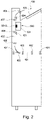
- FIG. 2 is a schematic view of an adjusting unit in the embodiment 1.
- FIG. 3 is a schematic view of a color sensor of a measuring unit in the embodiment 1.
- FIG. 4 is a schematic view of a moving unit of the measuring unit in the embodiment 1.
- FIG. 5 is a schematic view of the moving unit of the measuring unit in the embodiment 1.
- FIG. 6 is a schematic view of a feeding unit of the measuring unit in the embodiment 1.
- FIG. 7 is a schematic view of the feeding unit of the measuring unit in the embodiment 1.
- Parts (a) to (d) of FIG. 8 are schematic views for illustrating a color measuring operation of the measuring unit in the embodiment 1.
- FIG. 9 is a schematic view for illustrating a sheet feeding operation after the color measuring operation in the embodiment 1.
- FIG. 10 is a schematic view for illustrating the sheet feeding operation after the color measuring operation in the embodiment 1.
- Part (a) of FIG. 11 is a graph showing a moving speed of a sheet trailing end in the embodiment 1
- part (b) of FIG. 11 is a graph showing a driving speed of a discharging roller pair in the embodiment 1.
- Part (a) of FIG. 12 is a graph showing a moving speed of a sheet trailing end in an embodiment 2
- part (b) of FIG. 12 is a graph showing a driving speed of the discharging roller pair in the embodiment 2.
- FIG. 1 is a schematic view showing an image forming system 100 S according to a first embodiment (embodiment 1).
- the image forming system 100 S includes an image forming apparatus 100 , an adjusting unit 400 and a finisher 600 .
- the image forming apparatus 100 is an image forming apparatus in this embodiment
- the adjusting unit 400 is a measuring device in this embodiment
- the finisher 600 is a sheet processing device in this embodiment.
- an image forming engine 102 and a control board accommodating portion for accommodating a printer controller described later for controlling an operation of the image forming system 100 S including the image forming apparatus 100 .
- the image forming engine 102 in this embodiment includes an optical processing mechanism and a fixing processing mechanism which are used for forming an image on a recording material by an electrophotographic process, and a feeding processing mechanism and a conveying processing mechanism which are used for feeding and conveying a sheet 110 used as the recording material.
- the recording material it is possible to use sheet materials including papers such as plain paper and thick paper, surface-treated papers such as coated paper and embossed paper, a plastic film, a cloth, and the like.
- the optical processing mechanism 10 includes stations 120 , 121 , 122 and 123 for forming toner images of colors of yellow, magenta, cyan and black and includes an intermediary transfer belt 106 .
- stations 120 to 123 a surface of a photosensitive drum 105 which is a drum-shaped photosensitive member is electrically charged by a primary charger 111 .
- a laser scanner portion 107 performs an exposure process of the photosensitive drum 105 on the basis of an instruction signal which is formed on the basis of the image data and which is sent to the laser scanner portion 107 .
- the laser scanner portion 107 includes a laser driver for turning on and off an unshown semiconductor laser to emit laser light.
- the laser scanner portion 107 guides the laser light from the semiconductor laser to the photosensitive drum 105 through a reflection mirror 109 while dividing the laser light into portions by a rotatable polygonal mirror with respect to a main scan direction. By this, on the surface of the photosensitive drum 105 , an electrostatic latent image corresponding to the image data is formed.
- a developing device 112 accommodates therein a developer containing toner and supplies charged toner particles to the photosensitive drum 105 .
- the toner particles are deposited on the drum surface depending on a surface potential distribution, so that the electrostatic latent image carried on the photosensitive drum 105 is visualized as a toner image.
- the toner image carried on the photosensitive drum 105 is transferred (primary-transferred) onto the intermediary transfer belt 106 to which a voltage of a polarity opposite to a normal charge polarity of the toner is applied.
- toner images formed by the four stations 120 to 123 are multiple-transferred onto the intermediary transfer belt 106 so as to be superposed on each other, so that a full-color toner image is formed on the intermediary transfer belt 106 .
- the feeding processing mechanism feeds sheets 110 one by one toward a transfer roller 114 from a sheet accommodating portion 113 inserted into the casing 101 of the image forming apparatus 100 so as to be capable of being pulled out.
- the toner image carried on the intermediary transfer belt 106 which is an intermediary transfer member is transferred (secondary-transferred) onto the sheet 110 by the transfer roller 114 .
- an image formation start position detecting sensor 115 for determining a print start position when the image formation is carried out, a feeding timing sensor 116 for timing feeding of the sheet 110 , and a density sensor 117 are provided.
- the density sensor 117 measures a density of a patch image carried on the intermediary transfer belt 106 .
- the printer controller adjusts an operation condition (for example, setting of a target charging potential of the primary charger 111 and a bias voltage of the developing device 112 ) of the optical processing mechanism 10 on the basis of a detection result of the density sensor 117 .
- the fixing processing mechanism in this embodiment is constituted by a first fixing device 150 and a second fixing device 160 .
- the first fixing device 150 includes a fixing roller 151 for applying heat to the sheet 110 , a pressing belt 152 for causing the sheet 110 to press-contact the fixing roller 151 , and a first post-fixing sensor 153 for detecting completion of a fixing process by the first fixing device 150 .
- Each of rollers including the fixing roller 151 is a hollow roller and includes therein a heater.
- the first fixing device 150 applies heat and pressure to the toner image on the sheet 110 while nipping and feeding the sheet 110 by the fixing roller 151 and the pressing belt 152 which constitute a rotatable member pair. By this, the toner particles are melted and then is stuck, so that an image is fixed on the sheet 110 .
- the second fixing device 160 is disposed downstream of the first fixing device 150 in a feeding passage of the sheet 110 .
- the second fixing device 160 has a function of enhancing glossiness of the image fixed on the sheet 110 by the first fixing device 150 and a function of ensuring a fixing property of the image on the sheet 110 .
- the second fixing device 160 includes a fixing roller 161 and a pressing roller 162 as a rotatable member pair for heating and pressing the image on the sheet 110 while feeding the sheet 110 , and a second post-fixing sensor 163 for detecting completion of a fixing process by the second fixing device 160 .
- the image forming apparatus 100 includes a circumventing feeding passage 130 for discharging the sheet 110 without via the second fixing device 160 for the purpose of reducing energy consumption.
- the sheet 110 sent from the first fixing device 150 is derived to either one of the second fixing device 160 and the circumventing feeding passage 130 by a first switching flapper 131 .
- the sheet 110 passed through the second fixing device 160 or the circumventing feeding passage 130 is derived to either one of discharge feeding passage 139 and a reverse feeding passage 135 by a second switching flapper 132 .
- the sheet 110 fed to the reverse feeding passage 135 is then subjected to detection of a position thereof by a reverse sensor 137 , so that a leading end and a trailing end of the sheet 110 with respect to a sheet feeding direction are changed to each other by a switch-back operation performed by reversing portion 136 .
- the sheet 110 on which the image is formed on a first surface thereof is fed toward the transfer roller 114 again via a re-feeding passage 138 in a state in which the leading end and the trailing end of the sheet 110 are changed to each other by the reversing portion 136 , and then an image is formed on a second surface of the sheet 110 .
- the sheet 110 on which image formation of one-side printing is ended or the sheet 110 on which image formation on the second surface of the sheet 110 in the double-side printing is discharged to an outside of the image forming apparatus 100 via the discharge feeding passage 139 .
- a switching flapper 134 capable of guiding the sheet 110 , switched back by the reversing portion 136 , toward the discharge feeding passage 139 is provided.
- an image reading apparatus 190 including a main body portion 192 fixed to the casing 101 of the image forming apparatus 100 and including an automatic original feeding device (automatic document feeder (ADF)) 191 is provided.
- the ADF 191 includes a feeding tray 193 on which a sheet 2 which is an original is stacked and a discharge tray 198 on which the sheet 2 from which image information is read is discharged.
- the sheets 2 set on the feeding tray 193 are fed one by one by a feeding unit 194 , and the fed sheet 2 is conveyed via conveying roller pairs 197 a and 197 b .
- the sheet 2 is optically scanned by image sensors 195 and 196 , so that image information of the sheet 2 is read.
- the image sensor 195 for reading the image information from one surface of the sheet 2 is provided in the main body portion 192 , and the image sensor 196 for reading the image information form the other surface of the sheet 2 is provided at a lower portion of the ADF 191 .
- the sheet 2 from which the image information is read is discharged onto the discharge tray 198 by a discharging roller pair 197 c.
- an original (supporting) platen 199 is provided, so that the image reading apparatus 190 is capable of reading the image information from a surface of an object to be read, stationally placed on the original platen 199 , by moving the image sensor 195 .
- the ADF 191 is connected to the casing 101 of the image forming apparatus 100 via a hinge and is constituted so as to be openable upward from the original platen 199 .
- the image forming apparatus 100 is provided with an operating portion 180 ( FIG. 1 ) which is a user interface of the image forming system 100 S.
- the operating portion 180 includes a display as a display unit for displaying information to the user. Further, the operating portion 180 is provided with, for example, physical keys such as numeric keys and a print execution button and the like, and a touch panel function of the display as an input unit capable of inputting instructions and data from the user to the image forming system 100 S.
- the user is capable of inputting pieces of information indicating sheet attributes such as a name, a basis weight and the presence or absence of surface treatment of the sheet 110 set in the sheet accommodating portion 113 .
- the inputted attributes are registered in a sheet library 900 stored in the memory 304 .
- the adjusting unit 400 which is a measuring device of this embodiment will be described.
- the adjusting unit 400 is provided between the image forming apparatus 100 and the finisher 600 with respect to a horizontal direction (left-right direction in the figure). That is, an upstream device of the adjusting unit 400 in this embodiment is the image forming apparatus 100 , and a downstream device of the adjusting unit 400 is the finisher 600 .
- the finisher 600 includes a processing portion 601 for subjecting the sheet to processing such as a binding process, a saddle process and the like process, and discharges the processed sheet bundle (or the sheet received form the upstream device in the case where there is no need to perform the processes) as a product of the image forming system 100 S.
- the devices connected to the adjusting unit 400 on sides upstream and downstream device of the adjusting unit 400 change depending on a constitution of the image forming system 100 S.
- the adjusting unit 400 is not always directly connected to the image forming apparatus 100 , but a constitution in which an intermediary unit is provided between the image forming apparatus 100 and the adjusting unit 400 and in which the adjusting unit 400 receives the sheet from the intermediary unit may also be employed.
- the intermediary unit it is possible to cite a device for performing coating such that transparent toner is deposited on an image surface of the image-formed sheet and thus glossiness is imparted to the image.
- a sheet processing device other than the finisher 600 is connected to the adjusting unit 400 on a side downstream of the adjusting unit 400 .
- a sheet processing device it is possible to cite an inserter for inserting a sheet as a cover into the sheet bundle, a trimmer for cutting and uniformizing an end portion of a sheet bundle subjected to binding, and a stacker movable by a hard cart in a state in which a large volume of products is accommodated.
- the adjusting unit 400 is provided with a colorimetric unit 500 , and a through path 431 and a colorimetric path 432 which constitute a sheet feeding passage in the adjusting unit 400 . Further, at an upper portion of a casing of the adjusting unit 400 , a discharge tray 423 which is a stacking portion in this embodiment.
- the through path 431 is a feeding path along which the sheet discharge from the image forming apparatus 100 is received and fed toward the finisher 600 , and extends in a substantially horizontal direction.
- a first feeding roller pair 401 , a second feeding roller pair 402 , a third feeding roller pair 403 and a fourth feeding roller pair 404 are provided in a named order from an upstream side toward a downstream side with respect to the sheet feeding direction.
- the colorimetric path 432 branches from the through path 431 and extends upward.
- a first feeding roller pair 405 a second feeding roller pair 406 , a third feeding roller pair 407 and a discharging roller pair 408 are provided in a named order from an upstream side toward a downstream side of the colorimetric path 432 with respect to the sheet feeding direction.
- the colorimetric unit 500 including a color sensor 501 described later is provided.
- a switching flapper 422 which is a guiding member capable of switching a feeding passage of the sheet between the through path 431 and the colorimetric path 432 is provided.
- the sheet fed from the image forming apparatus 100 to the through path 431 is guided to the colorimetric path 432 by the switching flapper 422 .
- the second feeding roller pair 406 and the third feeding roller pair 407 is a named order, which are disposed in the colorimetric path 432 .
- a color of an image on the sheet is measured by the color sensor 501 .
- the sheet is discharged to the discharge tray 423 by the discharging roller pair 408 .
- sheet position sensors 421 and 604 are provided in the colorimetric path 432 .
- the sheet position sensor 421 is disposed upstream of a measuring position (a light incident portion on which reflected light from the sheet is incident) of the color sensor 501
- the sheet position sensor 604 is disposed downstream of a measuring position of the color sensor 501 .
- the sheet position sensors 421 and 604 for example, a photo-reflection for detecting reflected light from the sheet by emitting detection light toward a space of the feeding passage and a photo-interruptor for detecting that a flag member projecting toward the feeding passage is swung by being urged by the sheet are usable.
- FIG. 3 is a schematic view of the color sensor 501 as a measuring unit in this embodiment.
- the color sensor 501 is a sensor unit including a white LED 507 which is a light source, a line sensor 503 for detecting light intensity, and an optical system for guiding reflected light from a sheet 510 to the line sensor 503 by emitting the light from the light source to the sheet 510 .
- the white LED 507 irradiates a patch image 520 on the sheet 510 with light having a continuous spectrum.
- a diffraction grating 502 disperses the light reflected by the patch image 520 for each of wavelengths.
- the line sensor 503 is constituted by image pick-up elements 503 - 1 , . . . , 503 - n for n pixels, and measures intensity of light, for each of wavelengths, separated by the diffraction grating 502 .
- a wavelength area detectable by the line sensor 503 substantially ranges over entirety of a visible light area, and is set in a range of 380 nm to 720 nm, for example.
- the image pick-up elements 503 - 1 , . . . , 503 - n of the line sensor 503 it is possible to utilize a CMOS sensor.
- a lens 506 for concentrating light, reflected from the patch image 520 , on the diffraction grating 502 is provided.
- a detection signal of the line sensor 503 is processed by a processing (calculating) portion 504 mounted in the color sensor 501 , and a calculation result is stored in a memory 505 .
- the processing portion 504 includes a spectral processing portion for calculating a spectral reflectance of each of patch images 520 by performing spectral calculation from, for example, a light intensity value.
- a color management module (CMM) mounted in the image forming system 100 S converts inputted image data to device-independent data of a color space (for example, CIE L*a*b*color space), and thereafter converts the color space data to a signal for forming an image by the image forming engine 102 .
- a converting method from the device-independent color space to the color space for the image formation is defined by a color profile such as an international color consortium (ICC) profile.
- ICC international color consortium
- the color space for the image formation refers to a signal inputted, as a video signal, to the laser scanner portion 107 , for example.
- the image forming system 100 S In order that the image forming system 100 S outputs the image with high reproducibility relative to the inputted image data, there is a need to set a proper color profile. Therefore, in the image forming system 100 S, the color of the image formed on the sheet by the image forming engine 102 is measured by the color sensor 501 , so that a degree of approximation between a color of the inputted image data and a color represented by a measurement result is evaluated.
- an evaluation criterion for example, satisfaction of ⁇ E>4 in accordance with a color matching accuracy standard defined by ISO 12647-7 is employed.
- ⁇ E is a Euclidean distance between two points (for example, in CIE L*a*b*color space).
- the color profile is changed so as to satisfy the predetermined evaluation criterion, so that a color, a density and the like of the image outputted for the same inputted image data by the image forming engine 102 are adjusted and thus an output image high in color reproducibility is obtained.
- an image to be measured may also be an image test-printed as an image outputted in a current image forming job and may also be a test chart determined in advance by a standard such as ISO 12642.
- a test chart determined in advance by a standard such as ISO 12642.
- the color sensor of a spectral type was described as an example, but another measuring unit (for example, an image sensor unit including a combination of LEDs of three colors with a charge coupled device) capable of measuring the color of the image on the sheet may also be used.
- another measuring unit for example, an image sensor unit including a combination of LEDs of three colors with a charge coupled device
- the colorimetric unit 500 includes a moving unit 530 for moving the color sensor 501 , a moving motor 571 for driving the moving unit 530 , and a slide position sensor 545 for detecting the position of the color sensor 501 . Further, as shown in FIGS. 6 and 7 , as peripheral parts of the colorimetric unit 500 , a feeding unit 580 for feeding the sheet, and a feeding motor 590 for driving the feeding unit 580 are provided.
- the feeding unit 580 includes a second feeding roller pair 406 as a first roller pair in this embodiment, a third feeding roller pair 407 as a second roller pair in this embodiment, and a drive transmitting portion 589 for transmitting a driving force of the feeding motor 590 .
- a direction in which the sheet S is fed from the second feeding roller pair 406 toward the third feeding roller pair 407 is referred to as a “sheet feeding direction Da”.
- a widthwise direction (axial direction of a rotational axis of each of the second feeding roller pair 406 and the third feeding roller pair 407 ) perpendicular to the sheet feeding direction Da is referred to as a “main scan direction Db”.
- the colorimetric unit 500 is constituted so as to measure the color by the color sensor 501 while moving the color sensor 501 in the main scan direction Db by the moving unit 530 after receiving the sheet S fed in the sheet feeding direction Da along the colorimetric path 432 .
- the moving unit 530 includes a moving shaft 534 and a moving belt 533 which extend in the main scan direction Db, and includes a movement supporting plate 531 movable along the moving shaft 534 .
- the movement supporting plate 531 supports the color sensor 501 .
- the movement supporting plate 531 is provided with a bearing 532 slidably engageable with the moving shaft 534 , and the bearing 532 has a tooth surface engaging with the moving belt 533 .
- the moving belt 533 is stretched by two pulleys 572 (only one of which is shown in FIGS. 4 and 5 ) spaced from each other in the main scan direction Db, and is rotated with rotation of the moving motor 571 .
- the moving unit 530 is constituted so that the color sensor 501 is reciprocated in the main scan direction Db by moving the movement supporting plate 531 through rotation of the moving belt 533 by a driving force of a moving motor 571 .
- the adjusting unit 400 is provided with the slide position sensor 545 as a detecting unit for detecting the color sensor 501 .
- a photo-interruptor in which light is blocked by a flag portion 531 f provided on the movement supporting plate 531 can be used.
- a stepping motor is used as the moving motor 571 , it is possible to carry out positional control of the color sensor 501 with respect to the main scan direction Db by counting the number of driving pulses of the motor from a timing when an on state and an off state of the slide position sensor 545 are switched to each other.
- the feeding unit 580 includes a driving roller 581 and a follower roller 582 which constitute the second feeding roller pair 406 provided on a side upstream of the color sensor 501 and includes a driving roller 583 and a follower roller 584 which constitute the third feeding roller pair 407 provided on a side downstream of the color sensor 501 , and includes the drive transmitting portion 589 .
- the drive transmitting portion 589 is constituted by a driving pulley 585 mounted on an output shaft of the feeding motor 590 , follower pulleys 586 and 587 connected to the driving rollers 581 and 583 , respectively, a belt connecting the driving pulley 585 and the follower pulley 586 , and a belt connecting the driving pulley 585 and the follower pulley 587 .
- the driving rollers 581 and 583 are rotationally driven in a rotational direction R 1 along the sheet feeding direction Da, so that the follower rollers 582 and 584 are rotated by rotation of the driving rollers 581 and 583 , respectively.
- a feeding speed of the downstream-side third feeding roller pair 407 is set at a value larger than a value of a feeding speed of the upstream-side feeding roller pair 406 .
- the feeding speeds refer to peripheral speeds of the driving rollers 581 and 583 .
- the driving pulley 585 provided on the output shaft of the feeding motor 590 the number of teeth of a tooth surface connected to the third feeding roller pair 407 may only be required to be made larger than the number of teeth connected to the second feeding roller pair 406 .
- a ratio (speed ratio) of an angular speed of the driving roller 581 to an angular speed of the output shaft of the feeding motor 590 can be made smaller than a ratio (speed ratio) of an angular speed of the driving roller 583 to the angular speed of the output shaft of the feeding motor 590 .
- a method of creating a difference in feeding speed is not limited thereto, but for example, an outer diameter of the upstream-side driving roller 581 may also be set so as to be smaller than an outer diameter of the downstream-side driving roller 583 .
- a difference in feeding speed between the second feeding roller pair 406 and the third feeding roller pair 407 is provided in a simple constitution in which the second feeding roller pair 406 and the third feeding roller pair 407 are driven by a single feeding motor 590 .
- tension acts on the sheet.
- a distance from a light incident portion 501 S (lens 506 in FIG. 3 ) of the color sensor 501 to the sheet is stabilized, and thus contributes to an improvement in measurement accuracy of the color sensor 501 .
- the follower pulley 587 and the driving roller 583 of the third feeding roller pair 407 are not fixed to each other, and are connected to each other via a torque limiter 588 .
- the torque limiter 588 is divided into, for example, an inner ring portion and an outer ring portion, and the inner ring portion is mounted on a roller shaft of the driving roller 583 and the outer ring portion is connected to the follower pulley 587 .
- a slip when load of a predetermined torque value or more is exerted on the torque limiter 588 , a slip generates between the inner ring portion and the outer ring portion (i.e., the torque limiter 588 idles), and when the load is less than the predetermined torque value, the inner ring portion and the outer ring portion of the torque limiter 588 are rotated integrally with each other.
- a structure of the torque limiter is not limited to the above-described structure as long as the drive transmission is interrupted when the load of the predetermined torque value or more is exerted on the torque limiter 588 .
- the torque value of the torque limiter 588 is set so as to permit the torque limiter 588 idles through pulling of the third feeding roller pair 407 by the sheet.
- the driving roller 581 of the second feeding roller pair 406 and the pulley 586 are connected to each other so as not to rotate relative to each other. For this reason, in a period in which the sheet is nipped and fed between both the second feeding roller pair 406 and the third feeding roller pair 407 , the third feeding roller pair 407 is pulled by the sheet, so that a slip of the torque limiter 588 generates. Then, the third feeding roller pair 407 rotates at a peripheral speed equal to a peripheral speed of the second feeding roller pair 406 lower than the set feeding speed.
- FIGS. 7 to 9 An operation (color measuring operation) for measuring a color of a patch image P of a test chart by the color sensor 501 will be described using FIGS. 7 to 9 .
- a leading end (downstream end with respect to the sheet feeding direction Da) of the sheet S reaches the downstream-side belt feeding roller pair 407 and the sheet S is nipped and fed by the second feeding roller pair 406 and the third feeding roller pair 407 .
- a position of the sheet S with respect to the sheet feeding direction Da is controlled on the basis of a driving amount of the feeding motor 590 from a detection timing when the leading end of the sheet is detected by, for example, the sheet position sensors 421 and 604 ( FIG. 2 ).
- patch images are formed on the sheet S in m rows from P 1 to Pm, and a patch image group in each row is constituted by n patch images P 1 - 1 , P 1 - 2 , P 1 - 3 , . . . , P 1 - n . That is, in the following, a test chart on which the patch images are formed on a single sheet in a lattice shape with m rows and n columns would be considered.
- the color sensor 501 When the sheet S is fed to a measuring position of the color sensor 501 , as shown in part (a) of FIG. 8 , the color sensor 501 is on stand-by at a position retracted from a passing range of the sheet S with respect to the main scan direction Db.
- the patch image P 1 in a leading row reaches the position of the light incident portion 501 S of the color sensor 501 with respect to the sheet feeding direction, feeding of the sheet S is stopped (interrupted). Then, as shown in part (b) of FIG. 8 , the color sensor 501 reads the color of the n patch images (P 1 - 1 to P 1 - n ) through movement thereof in the main scan direction Db.
- a feeding operation of the sheet S and a reciprocating operation of the color sensor 501 which are as described above are repeated, so that the colors of all the patch images in the lattices with the m rows and n columns.
- the leading end of the sheet S is delivered to the discharging roller pair 408 .
- the speed difference is provided between the second feeding roller pair 406 and the third feeding roller pair 407 which are disposed on sides upstream and downstream, respectively, of the color sensor 501 , so that as shown in FIG. 7 , the sheet S is in a stretched state when the sheet S is temporarily at rest during the color measuring operation.
- the color sensor 501 is capable of measuring the color of the patch image in a state in which the color sensor 501 and a distance A 1 from the light incident portion 501 S to the sheet S are stabilized.
- the feeding speed of the downstream-side third feeding roller pair 407 is set at a value larger than a value of the upstream-side second feeding roller pair 406 by 10%.
- a trailing end (upstream end with respect to the sheet feeding direction Da) of the sheet S passes through the second feeding roller pair 406 disposed on the side upstream of the color sensor 501 , the sheet S is further fed by the third feeding roller pair 407 and the discharging roller pair 408 .
- the tension does not act on the sheet S at a timing when the trailing end of the sheet S passes through the second feeding roller pair 406 , and therefore, the torque limiter 588 is in a connected state, so that the peripheral speed of the third feeding roller pair 407 is accelerated.
- a driving motor for the discharging roller pair 408 is subjected to accelerated control so that the peripheral speed of the discharging roller pair 408 increases.
- a driving speed of the third roller pair disposed downstream of the second roller pair disposed on the side downstream of the measuring unit is accelerated from a first speed (V 1 ) to a second speed (V 2 ) higher than the first speed (V 1 ).
- Part (a) of FIG. 11 shows a movement speed 704 of the trailing end of the sheet S. It is understood that the movement speed of the sheet S is accelerated from the feeding speed V 1 of the second feeding roller pair 406 to the feeding speed V 2 of the third feeding roller pair 407 by passing of the trailing end of the sheet S through the second feeding roller pair 406 .
- Part (b) of FIG. 11 shows a movement speed 605 (peripheral speed of the driving roller of the discharging roller pair 408 ) of the discharging roller pair 408 , and shows that the discharging roller pair 408 is accelerated in accordance with timing of passing of the trailing end of the sheet S through the second feeding roller pair 406 .
- the movement speed of the sheet is accelerated when the trailing end of the sheet passes through the upstream-side feeding roller pair.
- the discharging roller pair 408 is also accelerated in synchronism with the acceleration of the sheet, so that occurrence of a crease and pressing of the sheet between the third feeding roller pair 407 and the discharging roller pair 408 are suppressed and thus the sheet can be stably fed.
- the peripheral speed of the discharging roller pair 408 before the acceleration may preferably be substantially equal to the feeding speed of the second feeding roller pair 406 as shown in part (a) and (b) of FIG. 11 .
- the peripheral speed of the discharging roller pair 408 after the acceleration may preferably be substantially equal to the feeding speed of the third feeding roller pair 407 in a state in which there is no slip of the torque limiter 588 .
- a “timing when the trailing end of the sheet passes through the second feeding roller pair 406 ” which is acceleration timing of the discharging roller pair 408 is discriminated on the basis of a detection signal of the sheet position sensor 421 or 604 ( FIG. 2 ). For example, a timing of a lapse of a predetermined timing from a timing (detection timing) when a detection signal indicating passing of the trailing end of the sheet is outputted by the sheet position sensor 421 disposed upstream of the second feeding roller pair 406 is the “timing when the trailing end of the sheet passes through the second feeding roller pair 406 ”.
- the predetermined timing is a required timing when the trailing end of the sheet moves at the feeding speed V 1 from the sheet position sensor 421 to the second feeding roller pair 406 . Further, it is also possible to acquire the “timing when the trailing end of the sheet passes through the second feeding roller pair 406 ” on the basis of an elapsed time from a detection timing when a detect signal indicating the passing of the trailing end of the sheet is outputted by the sheet position sensor 604 disposed downstream of the second feeding roller pair 406 .
- acceleration timing of the discharging roller pair 408 is different from the acceleration timing in the embodiment 1.
- Constituent elements represented by reference numerals or symbols common to the embodiment 1 and this embodiment have substantially the same constitutions and functions, and in this embodiment, a portion different from the embodiment 1 will be principally described.
- Parts (a) and (b) of FIG. 12 correspond to parts (a) and (b) of FIG. 12 , respectively, in which part (a) of FIG. 12 represents a movement speed 606 of the trailing end of the sheet, and part (b) of FIG. 12 represents a driving speed 607 of the discharging roller pair 408 .
- part (a) of FIG. 12 represents a movement speed 606 of the trailing end of the sheet
- part (b) of FIG. 12 represents a driving speed 607 of the discharging roller pair 408 .
- the trailing end of the sheet passes through the second feeding roller pair 406 after the color measuring operation and then the sheet movement speed 606 is accelerated from the feeding speed V 1 of the second feeding roller pair 406 to the feeding speed V 2 of the third feeding roller pair 407 (part (a) of FIG. 12 ).
- the driving speed (V 2 ) of the discharging roller pair 408 after the trailing end of the sheet passes through the second feeding roller pair 406 is set at a value larger than a value of the driving speed (V 1 ) of the discharging roller pair 408 before the trailing end of the sheet passes through the second feeding roller pair 406 .
- a delay time ⁇ T is set relative to a timing when the trailing end of the sheet passes through the second feeding roller pair 406 . The reason why such a delay time ⁇ T is provided will be described below.
- a time from the timing when the trailing end of the sheet passes through the second feeding roller pair 406 until the torque limiter 588 released from the tension of the sheet is changed in state from a connection-released state to a connected state can vary.
- a deviation amount of a change (transition) time of such a torque limiter 588 is referred to as ⁇ T 1 .
- the timing when the trailing end of the sheet passes through the second feeding roller pair 406 can be determined on the basis of the detection timing of the sheet position sensor 421 or 604 as described above, but a variation occurs in timing when the trailing end of the sheet actually passes through the second feeding roller pair 406 .
- Such a variation in trailing end passing timing occurs due to a tolerance of an outer diameter of the third feeding roller pair 407 , a sheet position variation when the sheet position sensors 421 and 604 output the detection signals, and the like.
- a fluctuation amount of a timing when the trailing end of the sheet actually passes through the second feeding roller pair 406 is referred to as ⁇ T 2 .
- a timing when the torque limiter 588 is in the connected state and then the acceleration of the sheet occurs is capable of varying with a duration of a time of about ( ⁇ T 1 + ⁇ T 2 ). That is, if the discharging roller pair 408 is accelerated just at the above-described calculative time, for the time of about ( ⁇ T 1 + ⁇ T 2 ), there is a possibility that a state in which the feeding speed of the discharging roller pair 408 is higher than the peripheral speed of the third feeding roller pair 407 is formed and thus mutual pulling of the sheet between the discharging roller pair 408 and the third feeding roller pair 407 occurs.
- a timing when the acceleration of the discharging roller pair 408 is started is after the acceleration of the peripheral speed of the third feeding roller pair 407 is started, so that it is possible to suppress damage on the sheet and an overload on a motor and the like due to the pulling of the sheet between the roller pairs 407 and 408 .
- the delay time ⁇ T is sets, so that it becomes possible to prevent the above-described mutual pulling of the sheet leading to the damage on the sheet and the excessive load on the motor and the like, by the acceleration of the discharging roller pair 408 .
- the adjusting unit 400 provided with the colorimetric unit 500 including the color sensor 501 was described as an example, but the present invention may also be applied to an image reading apparatus in which a reading unit for reading the image information from the sheet is provided in place of the color sensor 501 .
- the image reading apparatus 190 shown in FIG. 1 includes the image sensor 196 as the reading unit.
- the image reading apparatus is not limited to the image reading apparatus incorporated in the image forming apparatus (system), but may also be image reading apparatuses for other uses, such as a bar code reader, an inspection device for a sheet-like product, and the like.
- the image forming system 100 S in a state in which the adjusting unit 400 as the measuring device is connected to a side portion of the image forming apparatus 100 was described.
- the present invention may also be applied to an image forming system in which a function of the adjusting unit 400 is incorporated in the same casing including the image forming engine 102 .
- a color sensor 509 as a measuring unit may also be provided in a reverse feeding passage in the image forming apparatus 100 .
Landscapes
- Engineering & Computer Science (AREA)
- General Engineering & Computer Science (AREA)
- Physics & Mathematics (AREA)
- General Physics & Mathematics (AREA)
- Theoretical Computer Science (AREA)
- Microelectronics & Electronic Packaging (AREA)
- Delivering By Means Of Belts And Rollers (AREA)
- Control Or Security For Electrophotography (AREA)
Abstract
Description
Claims (18)
Applications Claiming Priority (3)
| Application Number | Priority Date | Filing Date | Title |
|---|---|---|---|
| JP2020087091A JP2021181354A (en) | 2020-05-19 | 2020-05-19 | Measuring device, image reader and image forming system |
| JP2020-087091 | 2020-05-19 | ||
| JPJP2020-087091 | 2020-05-19 |
Publications (2)
| Publication Number | Publication Date |
|---|---|
| US20210365752A1 US20210365752A1 (en) | 2021-11-25 |
| US11501124B2 true US11501124B2 (en) | 2022-11-15 |
Family
ID=78606960
Family Applications (1)
| Application Number | Title | Priority Date | Filing Date |
|---|---|---|---|
| US17/320,458 Active US11501124B2 (en) | 2020-05-19 | 2021-05-14 | Measuring device, image reading apparatus and image forming system for controlling movement of a sheet |
Country Status (2)
| Country | Link |
|---|---|
| US (1) | US11501124B2 (en) |
| JP (1) | JP2021181354A (en) |
Families Citing this family (3)
| Publication number | Priority date | Publication date | Assignee | Title |
|---|---|---|---|---|
| JP2021183537A (en) | 2020-05-22 | 2021-12-02 | キヤノン株式会社 | Sheet transfer device and image formation system |
| JP7536512B2 (en) | 2020-05-29 | 2024-08-20 | キヤノン株式会社 | Image forming system |
| JP7669176B2 (en) * | 2021-04-13 | 2025-04-28 | キヤノン株式会社 | Image forming device |
Citations (33)
| Publication number | Priority date | Publication date | Assignee | Title |
|---|---|---|---|---|
| JP2009053346A (en) | 2007-08-24 | 2009-03-12 | Konica Minolta Business Technologies Inc | Image forming apparatus |
| US8087667B2 (en) | 2009-01-30 | 2012-01-03 | Canon Kabushiki Kaisha | Sheet processing apparatus and image forming apparatus |
| US20120275839A1 (en) | 2011-04-28 | 2012-11-01 | Canon Kabushiki Kaisha | Sheet storage device and image forming apparatus |
| US20120288310A1 (en) | 2011-05-11 | 2012-11-15 | Canon Kabushiki Kaisha | Sheet storage apparatus and image forming apparatus |
| JP2013054324A (en) | 2011-09-06 | 2013-03-21 | Canon Inc | Image forming apparatus |
| US8500122B2 (en) | 2010-05-17 | 2013-08-06 | Canon Kabushiki Kaisha | Sheet conveying apparatus, sheet processing apparatus, and image forming apparatus |
| US20130243451A1 (en) | 2011-09-06 | 2013-09-19 | Canon Kabushiki Kaisha | Image forming apparatus |
| US8550461B2 (en) | 2011-06-23 | 2013-10-08 | Canon Kabushiki Kaisha | Sheet stacking apparatus and image forming apparatus |
| US8613442B2 (en) | 2011-06-10 | 2013-12-24 | Canon Kabushiki Kaisha | Sheet storing apparatus and image forming apparatus |
| US20140030000A1 (en) | 2012-07-26 | 2014-01-30 | Canon Kabushiki Kaisha | Sheet processing apparatus and image forming apparatus |
| US8752837B2 (en) | 2011-06-15 | 2014-06-17 | Canon Kabushiki Kaisha | Sheet storage device and image forming apparatus |
| US20140185047A1 (en) | 2012-12-28 | 2014-07-03 | Canon Kabushiki Kaisha | Image forming apparatus |
| US8794617B2 (en) | 2011-07-29 | 2014-08-05 | Canon Kabushiki Kaisha | Sheet stacking apparatus and image forming apparatus |
| US8851468B2 (en) | 2012-04-27 | 2014-10-07 | Canon Kabushiki Kaisha | Sheet stacking apparatus and image forming apparatus |
| US9033330B2 (en) | 2012-02-17 | 2015-05-19 | Canon Kabushiki Kaisha | Sheet processing apparatus with two image forming devices |
| US9067753B2 (en) | 2012-04-27 | 2015-06-30 | Canon Kabushiki Kaisha | Sheet stacking apparatus and image forming apparatus |
| US9102497B2 (en) | 2012-04-27 | 2015-08-11 | Canon Kabushiki Kaisha | Sheet stacking apparatus, sheet processing apparatus and image forming apparatus |
| US20160366296A1 (en) * | 2015-06-10 | 2016-12-15 | Konica Minolta, Inc. | Image reading apparatus and image forming system |
| US9665055B2 (en) | 2013-11-01 | 2017-05-30 | Canon Kabushiki Kaisha | Sheet conveying apparatus, sheet processing apparatus and image forming apparatus |
| US9738469B2 (en) | 2015-08-06 | 2017-08-22 | Canon Kabushiki Kaisha | Sheet conveyance apparatus and image forming apparatus |
| US9890011B2 (en) | 2015-08-04 | 2018-02-13 | Canon Kabushiki Kaisha | Sheet processing apparatus and image forming apparatus |
| US9914611B2 (en) | 2015-08-04 | 2018-03-13 | Canon Kabushiki Kaisha | Sheet stacking apparatus and image forming apparatus |
| US9932194B2 (en) | 2015-08-04 | 2018-04-03 | Canon Kabushiki Kaisha | Sheet discharge apparatus and image forming apparatus having same |
| US20190127167A1 (en) | 2017-10-26 | 2019-05-02 | Canon Kabushiki Kaisha | Sheet conveyance apparatus and image forming apparatus |
| US10294059B2 (en) | 2015-06-25 | 2019-05-21 | Canon Kabushiki Kaisha | Image forming apparatus and sheet processing apparatus |
| US10317836B2 (en) | 2016-03-01 | 2019-06-11 | Canon Kabushiki Kaisha | Sheet stacking apparatus and an image forming apparatus |
| US20200041946A1 (en) | 2018-07-31 | 2020-02-06 | Canon Kabushiki Kaisha | Sheet feeding apparatus, and image forming apparatus |
| US20200089152A1 (en) * | 2018-09-14 | 2020-03-19 | Canon Kabushiki Kaisha | Image forming apparatus and control method thereof |
| US20200247627A1 (en) | 2019-01-31 | 2020-08-06 | Canon Kabushiki Kaisha | Sheet conveying apparatus and image forming apparatus |
| US10782639B2 (en) | 2018-09-13 | 2020-09-22 | Canon Kabushiki Kaisha | Measurement apparatus, image forming apparatus and image forming system |
| US20210087004A1 (en) | 2019-09-20 | 2021-03-25 | Canon Kabushiki Kaisha | Sheet feeding apparatus and image forming apparatus |
| US10981738B2 (en) | 2018-02-13 | 2021-04-20 | Canon Kabushiki Kaisha | Sheet feeding apparatus and image forming apparatus |
| US20210360116A1 (en) * | 2020-05-15 | 2021-11-18 | Canon Kabushiki Kaisha | Reading apparatus and image forming apparatus |
-
2020
- 2020-05-19 JP JP2020087091A patent/JP2021181354A/en active Pending
-
2021
- 2021-05-14 US US17/320,458 patent/US11501124B2/en active Active
Patent Citations (42)
| Publication number | Priority date | Publication date | Assignee | Title |
|---|---|---|---|---|
| JP2009053346A (en) | 2007-08-24 | 2009-03-12 | Konica Minolta Business Technologies Inc | Image forming apparatus |
| US8087667B2 (en) | 2009-01-30 | 2012-01-03 | Canon Kabushiki Kaisha | Sheet processing apparatus and image forming apparatus |
| US8240664B2 (en) | 2009-01-30 | 2012-08-14 | Canon Kabushiki Kaisha | Sheet processing apparatus and image forming apparatus |
| US8500122B2 (en) | 2010-05-17 | 2013-08-06 | Canon Kabushiki Kaisha | Sheet conveying apparatus, sheet processing apparatus, and image forming apparatus |
| US20120275839A1 (en) | 2011-04-28 | 2012-11-01 | Canon Kabushiki Kaisha | Sheet storage device and image forming apparatus |
| US20120288310A1 (en) | 2011-05-11 | 2012-11-15 | Canon Kabushiki Kaisha | Sheet storage apparatus and image forming apparatus |
| US8613442B2 (en) | 2011-06-10 | 2013-12-24 | Canon Kabushiki Kaisha | Sheet storing apparatus and image forming apparatus |
| US8752837B2 (en) | 2011-06-15 | 2014-06-17 | Canon Kabushiki Kaisha | Sheet storage device and image forming apparatus |
| US8550461B2 (en) | 2011-06-23 | 2013-10-08 | Canon Kabushiki Kaisha | Sheet stacking apparatus and image forming apparatus |
| US8794617B2 (en) | 2011-07-29 | 2014-08-05 | Canon Kabushiki Kaisha | Sheet stacking apparatus and image forming apparatus |
| US9971270B2 (en) | 2011-09-06 | 2018-05-15 | Canon Kabushiki Kaisha | Image forming apparatus |
| US20130243451A1 (en) | 2011-09-06 | 2013-09-19 | Canon Kabushiki Kaisha | Image forming apparatus |
| US20170102631A1 (en) | 2011-09-06 | 2017-04-13 | Canon Kabushiki Kaisha | Image forming apparatus |
| US9551966B2 (en) | 2011-09-06 | 2017-01-24 | Canon Kabushiki Kaisha | Image forming apparatus |
| JP2013054324A (en) | 2011-09-06 | 2013-03-21 | Canon Inc | Image forming apparatus |
| US9033330B2 (en) | 2012-02-17 | 2015-05-19 | Canon Kabushiki Kaisha | Sheet processing apparatus with two image forming devices |
| US9102497B2 (en) | 2012-04-27 | 2015-08-11 | Canon Kabushiki Kaisha | Sheet stacking apparatus, sheet processing apparatus and image forming apparatus |
| US9067753B2 (en) | 2012-04-27 | 2015-06-30 | Canon Kabushiki Kaisha | Sheet stacking apparatus and image forming apparatus |
| US8851468B2 (en) | 2012-04-27 | 2014-10-07 | Canon Kabushiki Kaisha | Sheet stacking apparatus and image forming apparatus |
| US20140030000A1 (en) | 2012-07-26 | 2014-01-30 | Canon Kabushiki Kaisha | Sheet processing apparatus and image forming apparatus |
| US9213293B2 (en) | 2012-12-28 | 2015-12-15 | Canon Kabushiki Kaisha | Image forming apparatus having measurement unit that irradiates a measurement image and measures light reflected therefrom, and having shielding unit that can be moved to block such irradiation and moved to not block such irradiation |
| JP2014131205A (en) | 2012-12-28 | 2014-07-10 | Canon Inc | Image forming apparatus |
| US20140185047A1 (en) | 2012-12-28 | 2014-07-03 | Canon Kabushiki Kaisha | Image forming apparatus |
| US9932195B2 (en) | 2013-11-01 | 2018-04-03 | Canon Kabushiki Kaisha | Sheet conveying apparatus, sheet processing apparatus and image forming apparatus |
| US9665055B2 (en) | 2013-11-01 | 2017-05-30 | Canon Kabushiki Kaisha | Sheet conveying apparatus, sheet processing apparatus and image forming apparatus |
| US20160366296A1 (en) * | 2015-06-10 | 2016-12-15 | Konica Minolta, Inc. | Image reading apparatus and image forming system |
| US10294059B2 (en) | 2015-06-25 | 2019-05-21 | Canon Kabushiki Kaisha | Image forming apparatus and sheet processing apparatus |
| US9890011B2 (en) | 2015-08-04 | 2018-02-13 | Canon Kabushiki Kaisha | Sheet processing apparatus and image forming apparatus |
| US9932194B2 (en) | 2015-08-04 | 2018-04-03 | Canon Kabushiki Kaisha | Sheet discharge apparatus and image forming apparatus having same |
| US10183829B2 (en) | 2015-08-04 | 2019-01-22 | Canon Kabushiki Kaisha | Sheet stacking apparatus and image forming apparatus |
| US9914611B2 (en) | 2015-08-04 | 2018-03-13 | Canon Kabushiki Kaisha | Sheet stacking apparatus and image forming apparatus |
| US9738469B2 (en) | 2015-08-06 | 2017-08-22 | Canon Kabushiki Kaisha | Sheet conveyance apparatus and image forming apparatus |
| US10317836B2 (en) | 2016-03-01 | 2019-06-11 | Canon Kabushiki Kaisha | Sheet stacking apparatus and an image forming apparatus |
| US20190127167A1 (en) | 2017-10-26 | 2019-05-02 | Canon Kabushiki Kaisha | Sheet conveyance apparatus and image forming apparatus |
| US10981738B2 (en) | 2018-02-13 | 2021-04-20 | Canon Kabushiki Kaisha | Sheet feeding apparatus and image forming apparatus |
| US20200041946A1 (en) | 2018-07-31 | 2020-02-06 | Canon Kabushiki Kaisha | Sheet feeding apparatus, and image forming apparatus |
| US10782639B2 (en) | 2018-09-13 | 2020-09-22 | Canon Kabushiki Kaisha | Measurement apparatus, image forming apparatus and image forming system |
| US20200387099A1 (en) | 2018-09-13 | 2020-12-10 | Canon Kabushiki Kaisha | Measurement apparatus, image forming apparatus and image forming system |
| US20200089152A1 (en) * | 2018-09-14 | 2020-03-19 | Canon Kabushiki Kaisha | Image forming apparatus and control method thereof |
| US20200247627A1 (en) | 2019-01-31 | 2020-08-06 | Canon Kabushiki Kaisha | Sheet conveying apparatus and image forming apparatus |
| US20210087004A1 (en) | 2019-09-20 | 2021-03-25 | Canon Kabushiki Kaisha | Sheet feeding apparatus and image forming apparatus |
| US20210360116A1 (en) * | 2020-05-15 | 2021-11-18 | Canon Kabushiki Kaisha | Reading apparatus and image forming apparatus |
Also Published As
| Publication number | Publication date |
|---|---|
| JP2021181354A (en) | 2021-11-25 |
| US20210365752A1 (en) | 2021-11-25 |
Similar Documents
| Publication | Publication Date | Title |
|---|---|---|
| US10012939B2 (en) | Image forming apparatus and program product used in the image forming apparatus | |
| EP1387221B1 (en) | Image forming apparatus including speed detection mechanism for a rotary member | |
| US12063334B2 (en) | Image reading apparatus and image forming system | |
| US20210365752A1 (en) | Measuring device, image reading apparatus and image forming system | |
| US20160170355A1 (en) | Automatic document feeder, image reading device, image forming apparatus, and image forming system | |
| JP6819171B2 (en) | Image formation system and control program | |
| US20120269563A1 (en) | Transporting device and image forming apparatus using the same | |
| US20230280147A1 (en) | Sheet property measurement device and image forming apparatus | |
| CN113848690A (en) | Image forming apparatus and control method thereof | |
| US20260129130A1 (en) | Paper type identification apparatus and image forming apparatus | |
| US11418665B2 (en) | Image reading apparatus and image forming system | |
| JP6083953B2 (en) | Image reading apparatus and image forming apparatus | |
| CN119610910A (en) | Sheet detecting device and image forming apparatus | |
| US7802792B2 (en) | Image forming apparatus | |
| JP2025042188A (en) | Paper detection device, image forming device | |
| JP2000227694A (en) | Image forming device | |
| US20120018947A1 (en) | Image forming apparatus | |
| US8879940B2 (en) | Image forming apparatus which controls fluctuation of fixing rollers based on a detected interval between transferred sheets of recording media | |
| JP7618453B2 (en) | Reading device and image forming system | |
| US20230177670A1 (en) | Information processing apparatus and method of setting inspection condition of image | |
| CN102193382A (en) | Image forming apparatus using electrophotographic process | |
| US20090129796A1 (en) | Image forming apparatus | |
| US12535758B2 (en) | Sheet detection device and image forming apparatus | |
| JP7612426B2 (en) | Image reading device and image forming system | |
| JP2009251170A (en) | Image forming apparatus |
Legal Events
| Date | Code | Title | Description |
|---|---|---|---|
| FEPP | Fee payment procedure |
Free format text: ENTITY STATUS SET TO UNDISCOUNTED (ORIGINAL EVENT CODE: BIG.); ENTITY STATUS OF PATENT OWNER: LARGE ENTITY |
|
| AS | Assignment |
Owner name: CANON KABUSHIKI KAISHA, JAPAN Free format text: ASSIGNMENT OF ASSIGNORS INTEREST;ASSIGNORS:MORI, EIKOU;TOKUMA, NAOTO;SEKIGAWA, AKITO;SIGNING DATES FROM 20210414 TO 20210416;REEL/FRAME:056465/0440 |
|
| STPP | Information on status: patent application and granting procedure in general |
Free format text: DOCKETED NEW CASE - READY FOR EXAMINATION |
|
| STPP | Information on status: patent application and granting procedure in general |
Free format text: NOTICE OF ALLOWANCE MAILED -- APPLICATION RECEIVED IN OFFICE OF PUBLICATIONS |
|
| STPP | Information on status: patent application and granting procedure in general |
Free format text: DOCKETED NEW CASE - READY FOR EXAMINATION |
|
| STPP | Information on status: patent application and granting procedure in general |
Free format text: NOTICE OF ALLOWANCE MAILED -- APPLICATION RECEIVED IN OFFICE OF PUBLICATIONS |
|
| STPP | Information on status: patent application and granting procedure in general |
Free format text: PUBLICATIONS -- ISSUE FEE PAYMENT VERIFIED |
|
| STCF | Information on status: patent grant |
Free format text: PATENTED CASE |
|
| MAFP | Maintenance fee payment |
Free format text: PAYMENT OF MAINTENANCE FEE, 4TH YEAR, LARGE ENTITY (ORIGINAL EVENT CODE: M1551); ENTITY STATUS OF PATENT OWNER: LARGE ENTITY Year of fee payment: 4 |