US11486862B2 - Ultrasound image display method and apparatus, storage medium, and electronic device - Google Patents
Ultrasound image display method and apparatus, storage medium, and electronic device Download PDFInfo
- Publication number
- US11486862B2 US11486862B2 US16/935,421 US202016935421A US11486862B2 US 11486862 B2 US11486862 B2 US 11486862B2 US 202016935421 A US202016935421 A US 202016935421A US 11486862 B2 US11486862 B2 US 11486862B2
- Authority
- US
- United States
- Prior art keywords
- signal
- analytic
- sin
- cos
- analytic signal
- Prior art date
- Legal status (The legal status is an assumption and is not a legal conclusion. Google has not performed a legal analysis and makes no representation as to the accuracy of the status listed.)
- Active, expires
Links
Images


Classifications
-
- G—PHYSICS
- G01—MEASURING; TESTING
- G01N—INVESTIGATING OR ANALYSING MATERIALS BY DETERMINING THEIR CHEMICAL OR PHYSICAL PROPERTIES
- G01N29/00—Investigating or analysing materials by the use of ultrasonic, sonic or infrasonic waves; Visualisation of the interior of objects by transmitting ultrasonic or sonic waves through the object
- G01N29/04—Analysing solids
- G01N29/06—Visualisation of the interior, e.g. acoustic microscopy
- G01N29/0609—Display arrangements, e.g. colour displays
- G01N29/0645—Display representation or displayed parameters, e.g. A-, B- or C-Scan
-
- G—PHYSICS
- G06—COMPUTING OR CALCULATING; COUNTING
- G06T—IMAGE DATA PROCESSING OR GENERATION, IN GENERAL
- G06T15/00—Three-dimensional [3D] image rendering
- G06T15/005—General purpose rendering architectures
-
- G—PHYSICS
- G01—MEASURING; TESTING
- G01N—INVESTIGATING OR ANALYSING MATERIALS BY DETERMINING THEIR CHEMICAL OR PHYSICAL PROPERTIES
- G01N29/00—Investigating or analysing materials by the use of ultrasonic, sonic or infrasonic waves; Visualisation of the interior of objects by transmitting ultrasonic or sonic waves through the object
- G01N29/44—Processing the detected response signal, e.g. electronic circuits specially adapted therefor
- G01N29/46—Processing the detected response signal, e.g. electronic circuits specially adapted therefor by spectral analysis, e.g. Fourier analysis or wavelet analysis
-
- A—HUMAN NECESSITIES
- A61—MEDICAL OR VETERINARY SCIENCE; HYGIENE
- A61B—DIAGNOSIS; SURGERY; IDENTIFICATION
- A61B8/00—Diagnosis using ultrasonic, sonic or infrasonic waves
- A61B8/48—Diagnostic techniques
- A61B8/483—Diagnostic techniques involving the acquisition of a 3D volume of data
-
- G—PHYSICS
- G01—MEASURING; TESTING
- G01N—INVESTIGATING OR ANALYSING MATERIALS BY DETERMINING THEIR CHEMICAL OR PHYSICAL PROPERTIES
- G01N29/00—Investigating or analysing materials by the use of ultrasonic, sonic or infrasonic waves; Visualisation of the interior of objects by transmitting ultrasonic or sonic waves through the object
- G01N29/04—Analysing solids
- G01N29/06—Visualisation of the interior, e.g. acoustic microscopy
- G01N29/0609—Display arrangements, e.g. colour displays
-
- G—PHYSICS
- G01—MEASURING; TESTING
- G01S—RADIO DIRECTION-FINDING; RADIO NAVIGATION; DETERMINING DISTANCE OR VELOCITY BY USE OF RADIO WAVES; LOCATING OR PRESENCE-DETECTING BY USE OF THE REFLECTION OR RERADIATION OF RADIO WAVES; ANALOGOUS ARRANGEMENTS USING OTHER WAVES
- G01S15/00—Systems using the reflection or reradiation of acoustic waves, e.g. sonar systems
- G01S15/88—Sonar systems specially adapted for specific applications
- G01S15/89—Sonar systems specially adapted for specific applications for mapping or imaging
- G01S15/8906—Short-range imaging systems; Acoustic microscope systems using pulse-echo techniques
- G01S15/8977—Short-range imaging systems; Acoustic microscope systems using pulse-echo techniques using special techniques for image reconstruction, e.g. FFT, geometrical transformations, spatial deconvolution, time deconvolution
-
- G—PHYSICS
- G01—MEASURING; TESTING
- G01S—RADIO DIRECTION-FINDING; RADIO NAVIGATION; DETERMINING DISTANCE OR VELOCITY BY USE OF RADIO WAVES; LOCATING OR PRESENCE-DETECTING BY USE OF THE REFLECTION OR RERADIATION OF RADIO WAVES; ANALOGOUS ARRANGEMENTS USING OTHER WAVES
- G01S15/00—Systems using the reflection or reradiation of acoustic waves, e.g. sonar systems
- G01S15/88—Sonar systems specially adapted for specific applications
- G01S15/89—Sonar systems specially adapted for specific applications for mapping or imaging
- G01S15/8906—Short-range imaging systems; Acoustic microscope systems using pulse-echo techniques
- G01S15/8993—Three dimensional imaging systems
-
- G—PHYSICS
- G06—COMPUTING OR CALCULATING; COUNTING
- G06F—ELECTRIC DIGITAL DATA PROCESSING
- G06F17/00—Digital computing or data processing equipment or methods, specially adapted for specific functions
- G06F17/10—Complex mathematical operations
- G06F17/14—Fourier, Walsh or analogous domain transformations, e.g. Laplace, Hilbert, Karhunen-Loeve, transforms
-
- G—PHYSICS
- G06—COMPUTING OR CALCULATING; COUNTING
- G06T—IMAGE DATA PROCESSING OR GENERATION, IN GENERAL
- G06T15/00—Three-dimensional [3D] image rendering
-
- A—HUMAN NECESSITIES
- A61—MEDICAL OR VETERINARY SCIENCE; HYGIENE
- A61B—DIAGNOSIS; SURGERY; IDENTIFICATION
- A61B8/00—Diagnosis using ultrasonic, sonic or infrasonic waves
- A61B8/46—Ultrasonic, sonic or infrasonic diagnostic devices with special arrangements for interfacing with the operator or the patient
- A61B8/461—Displaying means of special interest
- A61B8/466—Displaying means of special interest adapted to display 3D data
-
- G—PHYSICS
- G01—MEASURING; TESTING
- G01N—INVESTIGATING OR ANALYSING MATERIALS BY DETERMINING THEIR CHEMICAL OR PHYSICAL PROPERTIES
- G01N2291/00—Indexing codes associated with group G01N29/00
- G01N2291/02—Indexing codes associated with the analysed material
- G01N2291/024—Mixtures
- G01N2291/02475—Tissue characterisation
-
- G—PHYSICS
- G01—MEASURING; TESTING
- G01S—RADIO DIRECTION-FINDING; RADIO NAVIGATION; DETERMINING DISTANCE OR VELOCITY BY USE OF RADIO WAVES; LOCATING OR PRESENCE-DETECTING BY USE OF THE REFLECTION OR RERADIATION OF RADIO WAVES; ANALOGOUS ARRANGEMENTS USING OTHER WAVES
- G01S15/00—Systems using the reflection or reradiation of acoustic waves, e.g. sonar systems
- G01S15/88—Sonar systems specially adapted for specific applications
- G01S15/89—Sonar systems specially adapted for specific applications for mapping or imaging
- G01S15/8906—Short-range imaging systems; Acoustic microscope systems using pulse-echo techniques
- G01S15/8909—Short-range imaging systems; Acoustic microscope systems using pulse-echo techniques using a static transducer configuration
- G01S15/8915—Short-range imaging systems; Acoustic microscope systems using pulse-echo techniques using a static transducer configuration using a transducer array
Definitions
- This application relates to the field of computers, and specifically, to display of an ultrasound image.
- Envelope detection is an important step of reconstruction of a brightness-mode ultrasound image (B-mode ultrasound image).
- a basic process of the reconstruction of the B-mode ultrasound image includes: acquiring a high-frequency radio frequency (RF) signal from an ultrasound probe, the original RF signal being a one-dimensional signal along a direction of the ultrasound probe; then performing the Hilbert transform on the one-dimensional signal to construct a one-dimensional analytic signal, an amplitude value of the one-dimensional analytic signal calculated being a one-dimensional envelope signal; and splicing a plurality of one-dimensional envelope signals into a two-dimensional signal according to a location of the probe, to acquire a two-dimensional envelope image and acquire a two-dimensional B-mode ultrasound image after some post-processing.
- a three-dimensional (3D) B-mode ultrasound image is mostly acquired after some post-processing is performed a 3D envelope image that is obtained through splicing based on one-dimensional envelope signals.
- Embodiments of this application provide an ultrasound image display method and apparatus, a storage medium and an electronic device, to improve the accuracy of a three-dimensional (3D) B-mode ultrasound image.
- the present disclosure describes a method for displaying an ultrasound image.
- the method includes acquiring, by a device, an input signal by performing detection on a to-be-detected object, the input signal comprising a three-dimensional (3D) radio-frequency (RF) signal.
- the device includes a memory storing instructions and a processor in communication with the memory.
- the method also includes performing, by the device, a modulus calculation on the 3D RF signal to obtain envelope information in a 3D ultrasound image, the modulus calculation being at least used for directly acquiring a 3D amplitude of the 3D RF signal; and displaying, by the device, the envelope information in the 3D ultrasound image, the envelope information being at least used for indicating the to-be-detected object.
- the present disclosure describes an apparatus for displaying an ultrasound image.
- the apparatus includes a memory storing instructions; and a processor in communication with the memory.
- the processor executes the instructions, the processor is configured to cause the apparatus to acquire an input signal by performing detection on a to-be-detected object, the input signal comprising a three-dimensional (3D) radio-frequency (RF) signal, perform a modulus calculation on the 3D RF signal to obtain envelope information in a 3D ultrasound image, the modulus calculation being at least used for directly acquiring a 3D amplitude of the 3D RF signal, and display the envelope information in the 3D ultrasound image, the envelope information being at least used for indicating the to-be-detected object.
- 3D three-dimensional
- RF radio-frequency
- the present disclosure describes a non-transitory computer readable storage medium storing computer readable instructions.
- the computer readable instructions when executed by a processor, are configured to cause the processor to perform acquiring an input signal by performing detection on a to-be-detected object, the input signal comprising a three-dimensional (3D) radio-frequency (RF) signal; performing a modulus calculation on the 3D RF signal to obtain envelope information in a 3D ultrasound image, the modulus calculation being at least used for directly acquiring a 3D amplitude of the 3D RF signal; and displaying the envelope information in the 3D ultrasound image, the envelope information being at least used for indicating the to-be-detected object.
- 3D three-dimensional
- RF radio-frequency
- an electronic device including a memory and a processor, the memory storing a computer program, and the processor being configured to perform any ultrasound image display method in the embodiments of this application through the computer program.
- FIG. 1 is a schematic diagram of a hardware environment of an ultrasound image display method according to an embodiment of this application.
- FIG. 2 is a flowchart of an optional ultrasound image display method according to an embodiment of this application.
- FIG. 3 is a schematic diagram of forming a plane by splicing envelopes of one-dimensional signals in the related art.
- FIG. 4 is a schematic diagram of 8 orthants in a 3D frequency domain according to an embodiment of this application.
- FIG. 5 is a schematic diagram of a platform where a three-dimensional (3D) radio-frequency (RF) signal is collected according to an embodiment of this application.
- 3D three-dimensional radio-frequency
- FIG. 6 is a structural diagram of a 3D RF signal according to an embodiment of this application.
- FIG. 7 is a comparison diagram of an envelope image in a 3D ultrasound image according to an embodiment of this application.
- FIG. 8 is an enlarged schematic diagram of an envelope image in a 3D ultrasound image according to an embodiment of this application.
- FIG. 9 is an enlarged schematic diagram of a brightness comparison in the vertical direction according to an embodiment of this application.
- FIG. 10 is an enlarged schematic diagram of a brightness comparison in the biopsy needle direction according to an embodiment of this application.
- FIG. 11 is a schematic diagram of a platform where a 3D RF signal is collected by a linear probe according to an embodiment of this application.
- FIG. 12 is a structural diagram of a 3D RF signal collected by a linear probe according to an embodiment of this application.
- FIG. 13 is a comparison diagram of an envelope image in a 3D ultrasound image collected by a linear probe according to an embodiment of this application.
- FIG. 14 is a schematic diagram of a brightness comparison of an envelope image in the vertical direction in a 3D ultrasound image collected by a linear probe according to an embodiment of this application.
- FIG. 15 is a schematic diagram of a brightness comparison of an envelope image in the biopsy needle direction in a 3D ultrasound image collected by a linear probe according to an embodiment of this application.
- FIG. 16 is a schematic diagram of an optional ultrasound image display apparatus according to an embodiment of this application.
- FIG. 17 is a structural block diagram of an electronic device according to an embodiment of this application.
- terms, such as “a”, “an”, or “the”, again, may be understood to convey a singular usage or to convey a plural usage, depending at least in part upon context.
- the term “based on” or “determined by” may be understood as not necessarily intended to convey an exclusive set of factors and may, instead, allow for existence of additional factors not necessarily expressly described, again, depending at least in part on context.
- an ultrasound image display method is provided.
- the ultrasound image display method may be applied to a hardware environment composed of a server 102 and a detection device 104 shown in FIG. 1 .
- the server 102 is connected to the detection device 104 by a network 110 .
- the network 110 includes, but is not limited to, a wide area network, a metropolitan area network or a local area network.
- the detection device 104 may include, but is not limited to, an ultrasound device.
- the ultrasound image display method in this embodiment of this application may be performed by the detection device 104 and a display device together.
- the specific execution process may be described as: acquiring, by the detection device, an input signal obtained by performing detection on a to-be-detected object by the detection device, the input signal being a three-dimensional (3D) radio-frequency (RF) signal; performing a one-time modulus value calculation on the 3D RF signal to obtain envelope information in a 3D ultrasound image, the one-time modulus value calculation being at least used for directly acquiring a 3D amplitude of the 3D RF signal; generating, by the detection device, the 3D ultrasound image according to the envelope information and sending the 3D ultrasound image to the display device; and displaying the envelope information in the 3D ultrasound image on the display device, the envelope information being used for indicating the to-be-detected object.
- 3D radio-frequency
- the detection device and the display device may form an integral structure.
- the detection device 104 shown in FIG. 1 is the integral structure composed of the detection device and the display device.
- the detection device and the display device may be separate components.
- the detection device is configured to generate the 3D ultrasound image and the display device is configured to display the 3D ultrasound image.
- FIG. 2 is a flowchart of an optional ultrasound image display method according to an embodiment of this application. As shown in FIG. 2 , the method may include the following steps:
- the modulus calculation on the 3D RF signal may include a one-time modulus value calculation on the 3D RF signal to obtain the envelope information in the 3D ultrasound image.
- the detection device may include, but is not limited to, an ultrasound device.
- the detection device may be configured to detect the to-be-detected object, a type of the to-be-detected object being not specifically limited in this embodiment of this application.
- the to-be-detected object may be a human organ (for example, the kidney or the liver).
- the detection device may send a detection signal.
- a signal obtained after the detection signal is reflected by the to-be-detected object is an input signal, where the input signal may be a real signal and/or the input signal may be a high-frequency 3D RF signal.
- the modulus calculation may be performed on the input signal, that is, the modulus calculation is performed on the 3D RF signal, to obtain the envelope information in the 3D ultrasound image, where the envelope information in the 3D ultrasound image may be used for indicating the to-be-detected object.
- the modulus calculation may at least be used for directly acquiring the 3D amplitude of the 3D RF signal, where the envelope information may include the 3D amplitude of the 3D RF signal.
- the modulus calculation by performing the modulus calculation on the 3D RF signal, the envelope information in the 3D ultrasound image is obtained.
- this embodiment of this application may make the brightness of the to-be-detected object indicated by the envelope information in the 3D ultrasound image be greater than the brightness of the to-be-detected object in a one-dimensional ultrasound image or a two-dimensional ultrasound image, to clearly display the to-be-detected object in the 3D ultrasound image, thereby improving the accuracy of the 3D ultrasound image.
- S 204 of performing the modulus calculation on the 3D RF signal may include the following S 2042 and S 2044 :
- the acquiring the first hypercomplex signal corresponding to the input signal may include: acquiring a second hypercomplex signal corresponding to the input signal, the second hypercomplex signal including 8 components, and each component being represented by the Hilbert transform of the input signal; acquiring a correspondence between the components represented by the Hilbert transform and the modulus values and angles of the plurality of analytic signals; and transforming the second hypercomplex signal into the first hypercomplex signal according to the correspondence.
- the input signal of the 3D RF signal may be defined as f(x, y, z) herein, and a hypercomplex signal ⁇ cas (x, y, z) of f(x, y, z) is defined as formula (3):
- ⁇ cas ⁇ ( x , y , z ) f ⁇ ( x , y , z ) ⁇ ⁇ ⁇ ⁇ [ ⁇ ⁇ ( x ) + e 1 ⁇ ⁇ ⁇ x ] ⁇ [ ⁇ ⁇ ( y ) + e 2 ⁇ ⁇ ⁇ y ] ⁇ [ ⁇ ⁇ ( z ) + e 3 ⁇ ⁇ ⁇ z ] ⁇ . ( 3 )
- the hypercomplex signal ⁇ cas (x, y, z) uses 3 bases of complex units: e 1 , e 2 , and e 3 , to define an imaginary unit.
- the theoretical foundation thereof is derived from the definition of a biquaternion. The following explains related contents:
- FIG. 3 is a schematic diagram of sending a RF signal by a 3D ultrasound fan-shaped probe.
- the high-frequency signal f(x) represents a one-dimensional RF signal sent by the ultrasound probe.
- a plurality of one-dimensional RF signals form one plane and a plurality of planes form one piece of 3D RF volume data.
- H ⁇ f ⁇ represents the Hilbert transform of signal f(x, y, z).
- H z ⁇ f ⁇ represents the Hilbert transform of signal f(x, y, z) in the z direction
- H y ⁇ f ⁇ represents the Hilbert transform of signal f(x, y, z) in the y direction
- H x ⁇ f ⁇ represents the Hilbert transform of signal f(x, y, z) in the x direction
- H yz ⁇ f ⁇ represents the Hilbert transform of signal f(x, y, z) in the y direction and the z direction
- H xz ⁇ f ⁇ represents the Hilbert transform of signal f(x, y, z) in the x direction and the z direction
- H xy ⁇ f ⁇ represents the Hilbert transform of signal f(x, y, z) in the x direction and the y direction.
- ⁇ cas ⁇ ( x , y , z ) f + iH yz ⁇ ⁇ f ⁇ + j ⁇ ( - H xz ⁇ ⁇ f ⁇ ) + kH xy ⁇ ⁇ f ⁇ + ⁇ ⁇ ( - H ⁇ ⁇ f ⁇ ) + ⁇ ⁇ ⁇ iH x ⁇ ⁇ f ⁇ + ⁇ ⁇ ⁇ jH y ⁇ ⁇ f ⁇ + ⁇ ⁇ ⁇ kH z ⁇ ⁇ f ⁇ ( 7 )
- the hypercomplex signal in formula (7) is the second hypercomplex signal in this embodiment of this application.
- the second hypercomplex signal corresponding to the input signal f(x, y, z) of the 3D RF signal is shown in formula (7).
- Each component of the hypercomplex signal is represented by the Hilbert transform of the input signal.
- Formula (7) is a theoretical value. Next, each component needs to be calculated from the perspective of engineering, and then the amplitude value (theoretical value) of the hypercomplex signal is calculated, thereby acquiring the amplitude value (theoretical value) of the hypercomplex signal from the perspective of engineering.
- the foregoing content defines the hypercomplex signal in a form of convolution, and defines the imaginary unit of the hypercomplex signal by using three bases of the biquaternion.
- the beneficial effect is that the form of definition is a macroscopic form of a conventional complex number and a quaternion, and may process 3D data and express the conventional complex number (one real part and one imaginary part) and the quaternion (one real part and three imaginary parts) in a downward compatible manner.
- a method for indirectly calculating the Hilbert transform in each component of the hypercomplex signal is needed to acquire a mathematical expression, of a result of formula (7), that can be implemented in engineering.
- Engineering implementation means that: it may be implemented by using a common programming language and an open code library.
- a calculated single-orthant analytic signal of f(x, y, z) is a signal obtained by performing inverse Fourier transform on a single orthant of a 3D Fourier spectrum of a real signal f(x, y, z).
- the signal may be calculated by using a Fourier transform function of a general programming language.
- One 3D real signal is first transformed from a 3D real number domain to a 3D frequency domain through the Fourier transform.
- There are 8 orthants in the 3D frequency domain as shown in FIG. 4 .
- the 3D frequency domain half of the spectrum includes all information about the whole original signal. Therefore, in the 8 orthants of the 3D frequency domain, four adjacent orthants may be selected to include all information about the input signal.
- FIG. 4 shows the eight orthants in the 3D frequency domain. It can be seen that, orthant I, orthant III, orthant V, and orthant VII are four adjacent orthants.
- the eight orthants in the 3D frequency domain are in FIG. 4 , where u, v, and w are 3 dimensions of the frequency domain.
- ⁇ 1 (x, y, z), ⁇ 3 (x, y, z), ⁇ 5 (x, y, z), and ⁇ 7 (x, y, z) represent single-orthant analytic signals respectively acquired from orthant I, orthant III, orthant V, and orthant VII of the frequency domain in FIG. 4 .
- the difference between the signal and the definition in formula (3) is that: the definition uses the unique imaginary unit i, that is the most conventional definition of the complex number (a complex number including one real part and one imaginary part).
- a 3D convolution of formula (8) to formula (11) has 8 components.
- the 8 components may each be represented by the Hilbert transform of the input signal f(x, y, z), which form real parts and imaginary parts of the single-orthant analytic signals.
- ⁇ 1 (x, y, z) represents the modulus value in the form of the polar coordinates of the complex number ⁇ 1 (x, y, z) ( ⁇ 1 herein may also be referred to as an amplitude value).
- ⁇ 1 (x, y, z) is shortened to ⁇ 1 .
- ⁇ 1 (x, y, z) represents the angle in the form of the polar coordinates of the complex number ⁇ 1 (x, y, z) ( ⁇ 1 may also be referred to as the phase herein).
- ⁇ 1 (x, y, z) is shortened to ⁇ 1 .
- a specific calculation method thereof is shown in formula (12):
- Formula (14) may be used for representing a correspondence between the components represented by the Hilbert transform and the modulus value and angle of the analytic signal in this embodiment of this application.
- Formula (14) uses the modulus value and angle of the analytic signal of the input signal to represent the Hilbert transform. It is relatively difficult to obtain, through a calculation, the left part of formula (14) in engineering, while the right part of formula (14) may be obtained through a calculation of a library function of the Fourier transform of the conventional programming language.
- ⁇ cas 1 4 ⁇ [ ( a 1 ⁇ cos ⁇ ⁇ ⁇ 1 + a 3 ⁇ cos ⁇ ⁇ ⁇ 3 + a 5 ⁇ cos ⁇ ⁇ ⁇ 5 + a 7 ⁇ cos ⁇ ⁇ ⁇ 7 ) + i ⁇ ( - a 1 ⁇ cos ⁇ ⁇ ⁇ 1 + a 3 ⁇ cos ⁇ ⁇ ⁇ 3 + a 5 ⁇ cos ⁇ ⁇ ⁇ 5 - a 7 ⁇ cos ⁇ ⁇ ⁇ 7 ) + j ⁇ ( a 1 ⁇ cos ⁇ ⁇ ⁇ 1 + a 3 ⁇ cos ⁇ ⁇ ⁇ 3 - a 5 ⁇ cos ⁇ ⁇ ⁇ 5 - a 7 ⁇ cos ⁇ ⁇ ⁇ 7 ) + k ⁇ ( - a 1 ⁇ cos ⁇ ⁇ ⁇ 1 + a 3 ⁇ cos ⁇ ⁇ ⁇ 3 - a 5 ⁇ co
- the hypercomplex signal in formula (15) is the first hypercomplex signal in this embodiment of this application.
- the foregoing content theoretically converts the content of the hypercomplex signal ⁇ cas (x, y, z) into an expression in another form, aiming to acquire an expression of the hypercomplex signal ⁇ cas (x, y, z) that can be implemented in engineering, as shown in formula (15).
- the modulus value of the first hypercomplex signal may be calculated.
- of the hypercomplex signal may be described as follows:
- Biquaternion property 1 multiplication of the biquaternion
- Biquaternion property 2 conjugate of the biquaternion
- conjugate of the biquaternion A may be defined as Ac, as shown in formula (18):
- p c is conjugate of quaternion p.
- the other part is a part that takes c as an imaginary unit, that is,
- is a modulus value
- ⁇ is an angle of the biquaternion.
- ⁇ cas ( ⁇ cas ) c
- 2 e 2 ⁇
- ch( ) and sh( ) are a hyperbolic cosine function and a hyperbolic sine function respectively.
- the specific derivation process of the formula is shown as follows:
- M represents real parts in formula (19) and formula (20), and N represents “pseudo real” parts in formula (19) and formula (20).
- M 2 ⁇ N 2
- 4 [ ch (2 ⁇ ) 2 ⁇ sh (2 ⁇ ) 2 ]
- ⁇ ⁇ cas ⁇ [ a 1 2 + a 3 2 + a 5 2 + a 7 2 4 ] 2 - [ a 1 ⁇ a 3 ⁇ sin ⁇ ( ⁇ 1 - ⁇ 3 ) - a 5 ⁇ a 7 ⁇ sin ⁇ ( ⁇ 5 - ⁇ 7 ) 2 ] 2 4 , ( 21 )
- a result of formula (21) is the modulus value
- Elements representing the modulus value come from calculations of formula (8) to formula (11).
- the calculations are calculation processes that can be implemented in engineering.
- Input information is modulus values ⁇ 1 (x, y, z), ⁇ 3 (x, y, z), ⁇ 5 (x, y, z), and ⁇ 7 (x, y, z) and angles ⁇ 1 (x, y, z), ⁇ 3 (x, y, z), ⁇ 5 (x, y, z), and ⁇ 7 (x, y, z) of polar coordinates of formula (8) to formula (11).
- Output is the modulus value of the first hypercomplex signal, that is, an envelope signal
- the modulus value of the first hypercomplex signal may be acquired according to the formula (21).
- represents the modulus value of the first hypercomplex signal
- ⁇ 1 is a modulus value of a first analytic signal
- ⁇ i is an angle of the first analytic signal
- the first analytic signal is an analytic signal that is in the first orthant of 8 orthants in a 3D frequency domain and that corresponds to the input signal
- ⁇ 3 is a modulus value of a third analytic signal
- ⁇ 3 is an angle of the third analytic signal
- the third analytic signal is an analytic signal that is in the third orthant of the 8 orthants in the 3D frequency domain and that corresponds to the input signal
- ⁇ 5 is a modulus value of a fifth analytic signal
- ⁇ 5 is an angle of the fifth analytic signal
- the fifth analytic signal is an analytic signal that is in the fifth orthant of the 8 orthants in the 3D frequency domain and that corresponds to the input signal
- ⁇ 7 is a modul
- the envelope information used for indicating the to-be-detected object in the 3D ultrasound image may be obtained.
- the 3D ultrasound image may be generated according to the envelope information.
- a process of generating the 3D ultrasound image according to the envelope information is not specifically limited herein, and may specifically include, but is not limited to, image processing means such as denoising.
- the 3D ultrasound image may be displayed on a display device and/or the envelope information in the 3D ultrasound image is displayed on the display device.
- the display device and the detection device may form an integral structure, or the display device and the detection device may be separate components.
- the 3D ultrasound image may be sent to the display device for displaying, so that a user may observe the to-be-detected object from the display device clearly and intuitively.
- the ultrasound image display method in this embodiment of this application because the envelope information used for indicating the to-be-detected object in the 3D ultrasound image is obtained by performing a modulus calculation on the 3D RF signal, but not obtained by splicing the one-dimensional envelope information, the brightness and definition of the to-be-detected object indicated by the envelope information in the 3D ultrasound image are greater than the brightness and definition of the to-be-detected object in a one-dimensional ultrasound image or a two-dimensional ultrasound image. Therefore, this embodiment of this application may make the to-be-detected object be more clearly displayed in the 3D ultrasound image, thereby improving the accuracy of the 3D ultrasound image.
- the ultrasound image display method provided in this application may be used to direct 3D envelope detection of the B-mode ultrasound image.
- an analytic signal of high-dimensional hypercomplex numbers is defined to calculate the 3D amplitude of the 3D RF signal at a time, that is, the 3D ultrasound image of the 3D RF signal.
- the Hilbert transform is used to implement an engineering implementation method for the provided hypercomplex signal and its modulus value.
- this application completely abandons the method for obtaining a B-mode ultrasound image by splicing one-dimensional envelope signals, to avoid a reconstruction error of the 3D B-mode ultrasound image that is formed by splicing the one-dimensional envelope signals.
- this application is further applicable to one-time envelope detection of a two-dimensional B-mode ultrasound image and a 3D B-mode ultrasound image.
- This application may be applied to a device that performs an envelope calculation on the 3D RF signal, for example, applied to B-mode imaging of a 3D ultrasound device.
- the method may implement one-time imaging on the 3D data.
- This application may implement the modulus calculation on a 3D RF ultrasound signal, to acquire a 3D envelope image thereof (that is, the image indicated by the envelope information in the foregoing embodiment of this application).
- the modulus value of the 3D RF ultrasound signal herein refers to the 3D envelope image.
- 3D ultrasound image may be obtained by using any two-dimensional or 3D image post-processing algorithm.
- a platform where a 3D fan-shaped ultrasound probe 510 is used to acquire a 3D RF signal is described by using an example.
- a phantom 530 is under the 3D fan-shaped ultrasound probe to imitate a human body.
- a biopsy needle 520 is inserted into the phantom 530 to imitate an experiment of inserting the biopsy needle into the human body to acquire human tissue for a subsequent biopsy.
- a doctor uses the ultrasound probe to observe a location of the biopsy needle in the human body, aiming to make a needle of the probe reach a predetermined tissue location.
- FIG. 6 is marked with 3 terms of coordinate axis directions used in the 3D ultrasound: axial 602 , lateral 604 , and elevation 606 .
- FIG. 6 also shows a ultrasound probe 610 and a biopsy needle 620 .
- the x axis and the y axis of the 3D RF signal form a slice.
- the z axis is an elevation axis that represents a different two-dimensional slice.
- the ultrasound envelope image of the 3D RF signal acquired in FIG. 6 is calculated separately by using the existing methods and the method provided in this application.
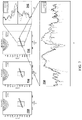
- FIG. 7 shows a part of the result, which is a result of slice 15 in FIG. 6 .
- the location of the biopsy needle is on the slice.
- Charts 710 and 720 are results calculated by using the existing one-dimensional method and two-dimensional method.
- Chart 730 is a result calculated by using the method for this application.
- a white area that is highlighted, diagonal, long and thin is the location of the biopsy needle. The higher brightness indicates that the biopsy needle is more apparently displayed on the ultrasound envelope image.
- chart 740 acquires profiles in a vertical direction of the image.
- Chart 750 is profiles along the direction of the probe. Higher values of the profiles indicate that the brightness is higher, that is, the probe is more clearly displayed on the envelope image. It can be seen from the values of the profiles that, the brightness in the 3D method provided in this application in the location of the probe is mostly higher than those in the one-dimensional method and/or the two-dimensional method.
- FIG. 8 is enlarged chart 730 .
- a diagonal quadrangular box is the location of the biopsy needle.
- Two imaginary lines are locations of the profiles in chart 740 and chart 750 .
- FIG. 9 is enlarged chart 740 .
- FIG. 10 is enlarged chart 750 .
- the middle of two horizontal lines in FIG. 9 is the location of the biopsy needle.
- the foregoing examples are two results based on the 3D RF data of the fan-shaped ultrasound probe.
- the following example is a calculation of the 3D envelope image based on the 3D RF data of the linear probe.
- a similar conclusion may also be drawn: the 3D envelope image of the solution can better display location information of the needle.
- FIG. 11 is a schematic diagram of a linear ultrasound probe 1110 .
- FIG. 11 also shows a biopsy needle 1120 and a phantom 1130 .
- FIG. 12 is a coordinate axis example of data acquired by the linear ultrasound probe 1210 , and the data is in a cubic structure including a plurality of slices, for example, slice 1 , slice 16 , and slice 29 .
- FIG. 13 is a result of a 3D envelope of the linear ultrasound probe.
- Chart 1310 is a result of the one-dimensional method
- chart 1320 is a result of the two-dimensional method
- chart 1330 is a result of the method of this application.
- FIG. 14 is a brightness comparison of pixels of the profiles in a vertical direction in the quadrangle.
- FIG. 15 is a brightness comparison of pixels of the profiles along the direction of the needle in the quadrangle. The whole curve is the location of the biopsy needle in the image. The brightness of the result of the 3D method is the highest, and the needle is displayed most apparently.
- the solution of this application may solve every envelope calculation of the 3D high-frequency signal mathematically.
- the solution may also solve the problem that the 3D signal is a high-frequency signal in one dimension or two dimensions but not a high-frequency signal in other dimensions. Therefore, the solution can be potentially applied to various physics and engineering application problems related to a modulus value calculation of 3D high-frequency signals, such as, high-frequency signal communications, high-frequency radar signal demodulation, encryption of images by using high-frequency information, and decryption requiring a calculation of envelope information of signals.
- the computer software product is stored in a storage medium (such as a read-only memory (ROM)/random access memory (RAM), a magnetic disk, or an optical disc), and includes several instructions for instructing a terminal device (which may be a mobile phone, a computer, a server, a network device, and the like) to perform the method described in the embodiments of this application.
- a storage medium such as a read-only memory (ROM)/random access memory (RAM), a magnetic disk, or an optical disc
- a terminal device which may be a mobile phone, a computer, a server, a network device, and the like
- FIG. 16 is a schematic diagram of an optional ultrasound image display apparatus according to an embodiment of this application. As shown in FIG. 16 , the apparatus may include:
- an acquiring unit 22 configured to acquire an input signal obtained by performing detection on a to-be-detected object by a detection device, the input signal being a 3D RF signal; a calculating unit 24 , configured to perform a modulus calculation on the 3D RF signal to obtain envelope information in a 3D ultrasound image, the modulus calculation being at least used for directly acquiring a 3D amplitude of the 3D RF signal; and a display unit 26 , configured to display the envelope information in the 3D ultrasound image on a display device, the envelope information being used for indicating the to-be-detected object.
- the acquiring unit 22 in this embodiment may be configured to perform step S 202 in the embodiments of this application
- the calculating unit 24 in this embodiment may be configured to perform step S 204 in the embodiments of this application
- the display unit 26 in this embodiment may be configured to perform step S 206 in the embodiments of this application.
- Implemented examples and application scenarios of the foregoing modules are the same as those of the corresponding steps, but are not limited to the content disclosed in the foregoing embodiments.
- the foregoing modules may be run in the hardware environment shown in FIG. 1 as a part of the apparatus, and may be implemented by software, or may be implemented by hardware.
- the calculating unit 24 may include: a first acquiring module, configured to acquire a first hypercomplex signal corresponding to the 3D RF signal, the first hypercomplex signal being a sum of 8 components, and each component being represented by modulus values and angles of a plurality of analytic signals corresponding to the input signal; and a second acquiring module, configured to acquire a modulus value of the first hypercomplex signal, the modulus value of the first hypercomplex signal being used for representing the 3D amplitude of the 3D RF signal, and envelope information including the modulus value of the first hypercomplex signal.
- the first acquiring module may include: a first acquiring submodule, configured to acquire a second hypercomplex signal corresponding to the 3D RF signal, the second hypercomplex signal including 8 components, and each component being represented by the Hilbert transform of the input signal; a second acquiring submodule, configured to acquire a correspondence between the components represented by the Hilbert transform and the modulus values and angles of the plurality of analytic signals; and a transforming module, configured to transform the second hypercomplex signal into the first hypercomplex signal according to the correspondence.
- the second acquiring module is configured to acquire the modulus value of the first hypercomplex signal according to the following formula:
- ⁇ ⁇ cas ⁇ [ a 1 2 + a 3 2 + a 5 2 + a 7 2 4 ] 2 - [ a 1 ⁇ a 3 ⁇ sin ⁇ ( ⁇ 1 - ⁇ 3 ) - a 5 ⁇ a 7 ⁇ sin ⁇ ( ⁇ 5 - ⁇ 7 ) 2 ] 2 4
- represents the modulus value of the first hypercomplex signal
- ⁇ 1 is a modulus value of a first analytic signal
- ⁇ 1 is an angle of the first analytic signal
- the first analytic signal is an analytic signal that is in the first orthant of 8 orthants in a 3D frequency domain and that corresponds to the input signal
- ⁇ 3 is a modulus value of a third analytic signal
- ⁇ 3 is an angle of the third analytic signal
- the third analytic signal is an analytic signal that is in the third orthant of the 8 orthants in the 3D frequency domain and that corresponds to the input signal
- ⁇ 5 is a modulus value of a fifth analytic signal
- ⁇ 5 is an angle of the fifth analytic signal
- the fifth analytic signal is an analytic signal that is in the fifth orthant of the 8 orthants in the 3D frequency domain and that corresponds to the input signal
- ⁇ 7 is a modulus
- the brightness of the to-be-detected object indicated by the envelope information in the 3D ultrasound image is greater than the brightness of the to-be-detected object in a one-dimensional ultrasound image or a two-dimensional ultrasound image.
- Implemented examples and application scenarios of the foregoing modules are the same as those of the corresponding steps, but are not limited to the content disclosed in the foregoing embodiments.
- the foregoing modules may be run in the hardware environment shown in FIG. 1 as a part of the apparatus, and may be implemented by software, or may be implemented by hardware.
- the to-be-detected object is accurately displayed in the 3D ultrasound image, to achieve a technical effect of improving the accuracy of the 3D ultrasound image, thereby solving the technical problem that the 3D B-mode ultrasound image reconstructed in the related art has a reconstruction error that reduces the accuracy of the 3D B-mode ultrasound image.
- an electronic device for implementing the ultrasound image display method is further provided.
- FIG. 17 is a structural block diagram of an electronic device according to an embodiment of this application.
- the electronic device may include: one or more (only one processor is shown in the figure) processors 201 and a memory 203 , the memory 203 storing a computer program, and the processor 201 being configured to run the computer program to perform the ultrasound image display method according to the embodiments of this application.
- the memory 203 may be configured to store a computer program and a module, for example, a program instruction/module corresponding to the ultrasound image display method and apparatus in the embodiments of this application, and the processor 201 performs various functional applications and data processing by running the computer program and the module stored in the memory 203 , that is, implementing the foregoing ultrasound image display method.
- the memory 203 may include a high-speed random access memory, and may further include a non-volatile memory, for example, one or more magnetic storage apparatuses, flash memories, or other non-volatile solid-state memories.
- the memory 203 may further include memories that are remotely disposed relative to the processor 201 , and the remote memories may be connected to a terminal via a network. Examples of the network include, but are not limited to, the Internet, an intranet, a local area network, a mobile communications network, and a combination thereof.
- the electronic device may further include: a transmission apparatus 205 and an input/output device 207 .
- the transmission apparatus 205 is configured to receive or send data through a network. Specific instances of the foregoing network may include a wired network and a wireless network.
- the transmission apparatus 205 includes a network interface controller (NIC), and the network interface controller may be connected to another network device or a router by using a network cable, so as to communicate with the Internet or a local area network.
- the transmission apparatus 205 is a radio frequency (RF) module, and the radio frequency module is configured to communicate with the Internet in a wireless manner.
- RF radio frequency
- the electronic device may be a terminal device such as a smartphone (such as an Android mobile phone or an iOS mobile phone), a tablet computer, a palmtop computer, a mobile Internet device (MID), or a PAD.
- FIG. 17 does not constitute a limitation on a structure of the foregoing electronic device.
- the electronic device may further include more or fewer components (for example, a network interface and a display apparatus) than those shown in FIG. 17 , or has a configuration different from that shown in FIG. 17 .
- the memory 203 may be configured to store the computer program.
- the processor is configured to run the computer program for performing the following steps: acquiring an input signal obtained by performing detection on a to-be-detected object by a detection device, the input signal being a 3D RF signal; performing a modulus calculation on the 3D RF signal to obtain envelope information in a 3D ultrasound image, the modulus calculation being at least used for directly acquiring a 3D amplitude of the 3D RF signal; and displaying the envelope information in the 3D ultrasound image on the display device, the envelope information being used for indicating the to-be-detected object.
- the processor 201 is further configured to perform the following steps: acquiring a first hypercomplex signal corresponding to the 3D RF signal, the first hypercomplex signal being a sum of 8 components, and each component being represented by modulus values and angles of a plurality of analytic signals corresponding to the input signal; and acquiring a modulus value of the first hypercomplex signal, the modulus value of the first hypercomplex signal being used for representing the 3D amplitude of the 3D RF signal, and envelope information including the modulus value of the first hypercomplex signal.
- the processor 201 is further configured to perform the following steps: acquiring a second hypercomplex signal corresponding to the 3D RF signal, the second hypercomplex signal including 8 components, and each component being represented by the Hilbert transform of the input signal; acquiring a correspondence between the components represented by the Hilbert transform and the modulus values and angles of the plurality of analytic signals; and transforming the second hypercomplex signal into the first hypercomplex signal according to the correspondence.
- the processor 201 is further configured to perform the following step: acquiring the modulus value of the first hypercomplex signal according to the following formula:
- ⁇ ⁇ cas ⁇ [ a 1 2 + a 3 2 + a 5 2 + a 7 2 4 ] 2 - [ a 1 ⁇ a 3 ⁇ sin ⁇ ( ⁇ 1 - ⁇ 3 ) - a 5 ⁇ a 7 ⁇ sin ⁇ ( ⁇ 5 - ⁇ 7 ) 2 ] 2 4
- represents the modulus value of the first hypercomplex signal
- ⁇ 1 is a modulus value of a first analytic signal
- ⁇ 1 is an angle of the first analytic signal
- the first analytic signal is an analytic signal that is in the first orthant of 8 orthants in a 3D frequency domain and that corresponds to the input signal
- ⁇ 3 is a modulus value of a third analytic signal
- ⁇ 3 is an angle of the third analytic signal
- the third analytic signal is an analytic signal that is in the third orthant of the 8 orthants in the 3D frequency domain and that corresponds to the input signal
- ⁇ 5 is a modulus value of a fifth analytic signal
- ⁇ 5 is an angle of the fifth analytic signal
- the fifth analytic signal is an analytic signal that is in the fifth orthant of the 8 orthants in the 3D frequency domain and that corresponds to the input signal
- ⁇ 7 is a modulus
- an ultrasound image display solution is provided.
- the input signal obtained by performing the detection on the to-be-detected object by the detection device, the input signal being the 3D RF signal; performing the modulus calculation on the 3D RF signal to obtain the envelope information in the 3D ultrasound image, the modulus calculation being at least used for directly acquiring the 3D amplitude of the 3D RF signal; and displaying the envelope information in the 3D ultrasound image on the display device, the envelope information being used for indicating the to-be-detected object, the to-be-detected object is accurately displayed in the 3D ultrasound image, to achieve a technical effect of improving the accuracy of the 3D ultrasound image, thereby solving the technical problem that the 3D B-mode ultrasound image reconstructed in the related art has a reconstruction error that reduces the accuracy of the 3D B-mode ultrasound image.
- a storage medium stores a computer program, the computer program being configured to perform a step of an ultrasound image display method in the foregoing embodiment when being run.
- the storage medium may be located in at least one network device of a plurality of network devices in a network shown in the foregoing embodiments.
- the storage medium is configured to store the computer program for performing the following steps:
- the storage medium is further configured to store the computer program for performing the following steps: acquiring a first hypercomplex signal corresponding to the 3D RF signal, the first hypercomplex signal being a sum of 8 components, and each component being represented by modulus values and angles of a plurality of analytic signals corresponding to the input signal; and acquiring a modulus value of the first hypercomplex signal, the modulus value of the first hypercomplex signal being used for representing the 3D amplitude of the 3D RF signal, and envelope information including the modulus value of the first hypercomplex signal.
- the storage medium is further configured to store the computer program for performing the following steps: acquiring a second hypercomplex signal corresponding to the 3D RF signal, the second hypercomplex signal including 8 components, and each component being represented by the Hilbert transform of the input signal; acquiring a correspondence between the components represented by the Hilbert transform and the modulus values and angles of the plurality of analytic signals; and transforming the second hypercomplex signal into the first hypercomplex signal according to the correspondence.
- the storage medium is further configured to store the computer program for performing the following step: acquiring the modulus value of the first hypercomplex signal according to the following formula:
- ⁇ ⁇ cas ⁇ [ a 1 2 + a 3 2 + a 5 2 + a 7 2 4 ] 2 - [ a 1 ⁇ a 3 ⁇ sin ⁇ ( ⁇ 1 - ⁇ 3 ) - a 5 ⁇ a 7 ⁇ sin ⁇ ( ⁇ 5 - ⁇ 7 ) 2 ] 2 4
- represents the modulus value of the first hypercomplex signal
- ⁇ 1 is a modulus value of a first analytic signal
- ⁇ i is an angle of the first analytic signal
- the first analytic signal is an analytic signal that is in the first orthant of 8 orthants in a 3D frequency domain and that corresponds to the input signal
- ⁇ 3 is a modulus value of a third analytic signal
- ⁇ 3 is an angle of the third analytic signal
- the third analytic signal is an analytic signal that is in the third orthant of the 8 orthants in the 3D frequency domain and that corresponds to the input signal
- ⁇ 5 is a modulus value of a fifth analytic signal
- ⁇ 5 is an angle of the fifth analytic signal
- the fifth analytic signal is an analytic signal that is in the fifth orthant of the 8 orthants in the 3D frequency domain and that corresponds to the input signal
- ⁇ 7 is a modul
- a person of ordinary skill in the art may understand that all or some of the steps of the methods in the foregoing embodiments may be implemented by a program instructing relevant hardware of the terminal device.
- the program may be stored in a computer-readable storage medium.
- the storage medium may include a flash disk, a read-only memory (ROM), a random access memory (RAM), a magnetic disk, an optical disc, and the like.
- the integrated unit in the foregoing embodiments When the integrated unit in the foregoing embodiments is implemented in the form of a software functional unit and sold or used as an independent product, the integrated unit may be stored in the foregoing computer-readable storage medium.
- the technical solution of this application essentially, or a part contributing to the related art, or all or a part of the technical solution may be implemented in a form of a software product.
- the computer software product is stored in a storage medium and includes several instructions for instructing one or more computer devices (which may be a personal computer, a server, a network device, or the like) to perform all or some of steps of the methods in the embodiments of this application.
- the disclosed client may be implemented in other manners.
- the described apparatus embodiment is merely an example.
- the unit division is merely logical function division and may be another division in an actual implementation.
- a plurality of units or components may be combined or integrated into another system, or some features may be ignored or not performed.
- the displayed or discussed mutual couplings or direct couplings or communication connections may be implemented by using some interfaces.
- the indirect couplings or communication connections between units or modules may be implemented in electric or other forms.
- the units described as separate parts may or may not be physically separate. Parts displayed as units may or may not be physical units, and may be located in one position, or may be distributed on a plurality of network units. Some or all of the units may be selected according to actual requirements to achieve the objectives of the solutions in the embodiments.
- functional units in the embodiments of this application may be integrated into one processing unit, or each of the units may exist alone physically, or two or more units are integrated into one unit.
- the integrated unit may be implemented in the form of hardware, or may be implemented in the form of a software function unit.
Landscapes
- Physics & Mathematics (AREA)
- Engineering & Computer Science (AREA)
- General Physics & Mathematics (AREA)
- Health & Medical Sciences (AREA)
- Life Sciences & Earth Sciences (AREA)
- Acoustics & Sound (AREA)
- Remote Sensing (AREA)
- Radar, Positioning & Navigation (AREA)
- General Health & Medical Sciences (AREA)
- Pathology (AREA)
- Mathematical Physics (AREA)
- Chemical & Material Sciences (AREA)
- Immunology (AREA)
- Biochemistry (AREA)
- Analytical Chemistry (AREA)
- Theoretical Computer Science (AREA)
- Data Mining & Analysis (AREA)
- Mathematical Optimization (AREA)
- Pure & Applied Mathematics (AREA)
- Mathematical Analysis (AREA)
- Computational Mathematics (AREA)
- Signal Processing (AREA)
- Computer Graphics (AREA)
- Computer Networks & Wireless Communication (AREA)
- Algebra (AREA)
- Databases & Information Systems (AREA)
- Software Systems (AREA)
- General Engineering & Computer Science (AREA)
- Spectroscopy & Molecular Physics (AREA)
- Radiology & Medical Imaging (AREA)
- Biomedical Technology (AREA)
- Heart & Thoracic Surgery (AREA)
- Medical Informatics (AREA)
- Molecular Biology (AREA)
- Surgery (AREA)
- Animal Behavior & Ethology (AREA)
- Public Health (AREA)
- Veterinary Medicine (AREA)
- Nuclear Medicine, Radiotherapy & Molecular Imaging (AREA)
- Biophysics (AREA)
Abstract
Description
f A(x)=f(x)+iH{f(x)},x∈
|f A(x)|=√{square root over (f(x)2+(H{f(x)})2)} (2)
[1,i=c 2 c 3 ,j=e 3 e 1 ,k=e 1 e 2 ,ϵ=−e 1 e 2 e 3 ,ϵi=e 1 ,ϵj=e 2 ,ϵk=e 3] (4)
α1 cos φ1 =f−H xy {f}−H xz {f}−H yz {f}
α1 sin φ1 =H x {f}+H y {f}+H z {f}−H{f} (13)
f=¼(α1 cos φ1+α3 cos φ3+α5 cos φ5+α7 cos φ7),
H yz {f}=¼(−α1 cos φ1+α3 cos φ3+α5 cos φ5−α7 cos φ7),
−H xz {f}=¼(α1 cos φ1+α3 cos φ3−α5 cos φ5−α7 cos φ7),
H xy {f}=¼(−α1 cos φ1+α3 cos φ3−α5 cos φ5+α7 cos φ7),
−H{f}=¼(α1 sin φ1−α3 sin φ3−α5 sin φ5+α7 sin φ7),
H x {f}=¼(α1 sin φ1+α3 sin φ3+α5 sin φ5+α7 sin φ7),
H y {f}=¼(α1 sin φ1−α3 sin φ3+α5 sin φ5−α7 sin φ7),
H z {f}=¼(α1 sin φ1+α3 sin φ3−α5 sin φ5−α7 sin φ7), (14)
AB=(p+ϵq)(p′+ϵq′)=(pp′+qq′)+ϵ(pq′+qp′) (17)
ψcas=|ψcas|eϵϕa,
ψcas(ψcas)c=|ψcas|2 e 2ϵϕ=|ψcas|2[ch(2ϕ)+ϵsh(2ϕ)], (20)
ψcas(ψcas)c =M+ϵN
M 2 −N 2=|ψcas|4[ch(2ϕ)2 −sh(2ϕ)2]=|ψcas|4
Claims (14)
f=¼(α1 cos φ1+α3 cos φ3+α5 cos φ5+α7 cos φ7),
H yz {f}=¼(−α1 cos φ1+α3 cos φ3+α5 cos φ5−α7 cos φ7),
−H xz {f}=¼(α1 cos φ1+α3 cos φ3−α5 cos φ5−α7 cos φ7),
H xy {f}=¼(−α1 cos φ1+α3 cos φ3−α5 cos φ5+α7 cos φ7),
−H{f}=¼(α1 sin φ1−α3 sin φ3−α5 sin φ5+α7 sin φ7),
H x {f}=¼(α1 sin φ1+α3 sin φ3+α5 sin φ5+α7 sin φ7),
H y {f}=¼(α1 sin φ1−α3 sin φ3+α5 sin φ5−α7 sin φ7),
H z {f}=¼(α1 sin φ1+α3 sin φ3−α5 sin φ5−α7 sin φ7).
f=¼(α1 cos φ1+α3 cos φ3+α5 cos φ5+α7 cos φ7),
H yz {f}=¼(−α1 cos φ1+α3 cos φ3+α5 cos φ5−α7 cos φ7),
−H xz {f}=¼(α1 cos φ1+α3 cos φ3−α5 cos φ5−α7 cos φ7),
H xy {f}=¼(−α1 cos φ1+α3 cos φ3−α5 cos φ5+α7 cos φ7),
−H{f}=¼(α1 sin φ1−α3 sin φ3−α5 sin φ5+α7 sin φ7),
H x {f}=¼(α1 sin φ1+α3 sin φ3+α5 sin φ5+α7 sin φ7),
H y {f}=¼(α1 sin φ1−α3 sin φ3+α5 sin φ5−α7 sin φ7),
H z {f}=¼(α1 sin φ1+α3 sin φ3−α5 sin φ5−α7 sin φ7),
Applications Claiming Priority (3)
| Application Number | Priority Date | Filing Date | Title |
|---|---|---|---|
| CN201810508663.2 | 2018-05-24 | ||
| CN201810508663.2A CN110163940B (en) | 2018-05-24 | 2018-05-24 | Ultrasonic image display method and device, storage medium and electronic device |
| PCT/CN2019/082216 WO2019223442A1 (en) | 2018-05-24 | 2019-04-11 | Ultrasound image display method and apparatus, and storage medium and electronic apparatus |
Related Parent Applications (1)
| Application Number | Title | Priority Date | Filing Date |
|---|---|---|---|
| PCT/CN2019/082216 Continuation WO2019223442A1 (en) | 2018-05-24 | 2019-04-11 | Ultrasound image display method and apparatus, and storage medium and electronic apparatus |
Publications (2)
| Publication Number | Publication Date |
|---|---|
| US20200348268A1 US20200348268A1 (en) | 2020-11-05 |
| US11486862B2 true US11486862B2 (en) | 2022-11-01 |
Family
ID=67644979
Family Applications (1)
| Application Number | Title | Priority Date | Filing Date |
|---|---|---|---|
| US16/935,421 Active 2039-12-25 US11486862B2 (en) | 2018-05-24 | 2020-07-22 | Ultrasound image display method and apparatus, storage medium, and electronic device |
Country Status (5)
| Country | Link |
|---|---|
| US (1) | US11486862B2 (en) |
| EP (1) | EP3806028B1 (en) |
| JP (1) | JP6941742B2 (en) |
| CN (1) | CN110163940B (en) |
| WO (1) | WO2019223442A1 (en) |
Families Citing this family (1)
| Publication number | Priority date | Publication date | Assignee | Title |
|---|---|---|---|---|
| JP2022041386A (en) * | 2020-09-01 | 2022-03-11 | キヤノンメディカルシステムズ株式会社 | Hypercomplex-number operation device and medical image diagnostic apparatus |
Citations (4)
| Publication number | Priority date | Publication date | Assignee | Title |
|---|---|---|---|---|
| JP2005087237A (en) | 2003-09-12 | 2005-04-07 | Aloka Co Ltd | Ultrasonic image processor |
| CN101061961A (en) | 2006-04-24 | 2007-10-31 | 株式会社东芝 | Ultrasonic imaging apparatus and a method of obtaining ultrasonic images |
| CN103512960A (en) * | 2013-09-27 | 2014-01-15 | 中国科学院声学研究所 | Ultrasound array imaging method |
| US20160238568A1 (en) | 2015-02-18 | 2016-08-18 | Riverside Research Institute | Typing and imaging of biological and non-biological materials using quantitative ultrasound |
Family Cites Families (5)
| Publication number | Priority date | Publication date | Assignee | Title |
|---|---|---|---|---|
| EP0596560A1 (en) * | 1992-11-04 | 1994-05-11 | Laboratoires D'electronique Philips | Apparatus for the examination of media by ultrasonic echography |
| US6579239B1 (en) * | 2002-04-05 | 2003-06-17 | Ge Medical Systems Global Technology Company, Llc | System and method for automatic adjustment of brightness and contrast in images |
| JP4945273B2 (en) * | 2006-04-24 | 2012-06-06 | 株式会社東芝 | Ultrasonic diagnostic apparatus and control program for ultrasonic diagnostic apparatus |
| WO2010131136A1 (en) * | 2009-05-13 | 2010-11-18 | Koninklijke Philips Electronics, N.V. | Ultrasonic blood flow doppler audio with pitch shifting |
| CN106934335B (en) * | 2015-12-31 | 2021-02-02 | 南通东华软件有限公司 | Image recognition method and device |
-
2018
- 2018-05-24 CN CN201810508663.2A patent/CN110163940B/en active Active
-
2019
- 2019-04-11 WO PCT/CN2019/082216 patent/WO2019223442A1/en not_active Ceased
- 2019-04-11 JP JP2020543587A patent/JP6941742B2/en active Active
- 2019-04-11 EP EP19808389.1A patent/EP3806028B1/en active Active
-
2020
- 2020-07-22 US US16/935,421 patent/US11486862B2/en active Active
Patent Citations (4)
| Publication number | Priority date | Publication date | Assignee | Title |
|---|---|---|---|---|
| JP2005087237A (en) | 2003-09-12 | 2005-04-07 | Aloka Co Ltd | Ultrasonic image processor |
| CN101061961A (en) | 2006-04-24 | 2007-10-31 | 株式会社东芝 | Ultrasonic imaging apparatus and a method of obtaining ultrasonic images |
| CN103512960A (en) * | 2013-09-27 | 2014-01-15 | 中国科学院声学研究所 | Ultrasound array imaging method |
| US20160238568A1 (en) | 2015-02-18 | 2016-08-18 | Riverside Research Institute | Typing and imaging of biological and non-biological materials using quantitative ultrasound |
Non-Patent Citations (6)
| Title |
|---|
| Bulow et al., "Hypercomplex Signals—A Novel Extension of the Analytic Signal to the Multidimensional Case," IEEE Transactions on Signal Processing, IEEE Service Center, New York, NY, Nov. 1, 2001, pp. 2844-2852. |
| Extended European Search Report regarding EP19808389 dated May 21, 2021. |
| International Search Report with English translation and Written Opinion regarding PCT/CN2019/082216 dated Jul. 8, 2019, 8 pages. |
| L. Wang, P. R. Girard, A. Bernard, Z. Liu, P. Clarysse, et al.. 3-D biquaternionic analytic signal and application to envelope detection in 3-D ultrasound imaging. 2nd International Conference on 3D Imaging, Dec. 2012, Liège, Belgium, pp. 1-8, (Year: 2012). * |
| Snopek, "The n-D analytic 2-5, 7-10 signals and Fourier spectra in complex and hypercomplex domains," Telecommunications and Signal Processing (TSP), 2011, 34th International Conference IEEE, Aug. 18, 2018, pp. 423-427. |
| Wang et al., "3-D biquaternionic analytic signal and application to envelope detection in 3-D ultrasound imaging," 2012 International Conference on 3D Imaging (IC3D), IEEE, Lyon, France, Dec. 3, 2012, pp. 1-8. |
Also Published As
| Publication number | Publication date |
|---|---|
| CN110163940B (en) | 2023-04-18 |
| EP3806028A1 (en) | 2021-04-14 |
| JP6941742B2 (en) | 2021-09-29 |
| JP2021513421A (en) | 2021-05-27 |
| US20200348268A1 (en) | 2020-11-05 |
| EP3806028A4 (en) | 2021-06-23 |
| CN110163940A (en) | 2019-08-23 |
| WO2019223442A1 (en) | 2019-11-28 |
| EP3806028B1 (en) | 2023-12-20 |
Similar Documents
| Publication | Publication Date | Title |
|---|---|---|
| US10957062B2 (en) | Structure depth-aware weighting in bundle adjustment | |
| US9192339B2 (en) | Scanning system and image display method | |
| CN109584168B (en) | Image processing method and apparatus, electronic device and computer storage medium | |
| US20180082421A1 (en) | Image processing system and method to reconstruct a three-dimensional (3d) anatomical surface | |
| KR20190059092A (en) | Method for reconstructing three dimension information of object and apparatus for the same | |
| CN111508058A (en) | Method and device for three-dimensional reconstruction of image, storage medium and electronic equipment | |
| CN114741652A (en) | Deconvolution high-resolution imaging method and system based on acoustic image instrument | |
| US11486862B2 (en) | Ultrasound image display method and apparatus, storage medium, and electronic device | |
| Georgiev et al. | Time-of-flight range measurement in low-sensing environment: Noise analysis and complex-domain non-local denoising | |
| JP5787398B2 (en) | Function calculation device, depth map generation device, function calculation method, and function calculation program | |
| US20160335771A1 (en) | Incremental global non-rigid alignment of three-dimensional scans | |
| WO2020175445A1 (en) | Learning method, learning device, generative model and program | |
| CN113470154B (en) | Image processing method, device, electronic equipment and storage medium | |
| CN110969578A (en) | Local grid map rapid splicing method, medium, terminal and device | |
| CN109345466B (en) | Electromagnetic imaging space-variant fuzzy recovery method and device | |
| CN118469809A (en) | Wafer image stitching method and device, electronic equipment and storage medium | |
| CN116363303A (en) | Three-dimensional reconstruction method, device, equipment and medium for multi-view two-dimensional ultrasound images | |
| US20180260965A1 (en) | Automatic global non-rigid scan point registration | |
| JP6260888B2 (en) | Function calculation device, function calculation method, and function calculation program | |
| CN110146880B (en) | Imaging method, terminal device, and computer storage medium | |
| CN109839608B (en) | Magnetic resonance field map determination method, magnetic resonance field map determination device, electronic apparatus, and storage medium | |
| CN119110051B (en) | Three-dimensional display method, device, electronic device and storage medium | |
| Wu et al. | Spatial and frequency-based super-resolution of ultrasound images | |
| US11461917B1 (en) | Measuring 3-dimensional distances in medical imaging data | |
| Fehr et al. | Fast and accurate rotation estimation on the 2-sphere without correspondences |
Legal Events
| Date | Code | Title | Description |
|---|---|---|---|
| AS | Assignment |
Owner name: TENCENT TECHNOLOGY (SHENZHEN) COMPANY LIMITED, CHINA Free format text: ASSIGNMENT OF ASSIGNORS INTEREST;ASSIGNOR:WANG, LIANG;REEL/FRAME:053280/0340 Effective date: 20200720 |
|
| FEPP | Fee payment procedure |
Free format text: ENTITY STATUS SET TO UNDISCOUNTED (ORIGINAL EVENT CODE: BIG.); ENTITY STATUS OF PATENT OWNER: LARGE ENTITY |
|
| STPP | Information on status: patent application and granting procedure in general |
Free format text: DOCKETED NEW CASE - READY FOR EXAMINATION |
|
| STPP | Information on status: patent application and granting procedure in general |
Free format text: NON FINAL ACTION MAILED |
|
| STPP | Information on status: patent application and granting procedure in general |
Free format text: RESPONSE TO NON-FINAL OFFICE ACTION ENTERED AND FORWARDED TO EXAMINER |
|
| STPP | Information on status: patent application and granting procedure in general |
Free format text: NOTICE OF ALLOWANCE MAILED -- APPLICATION RECEIVED IN OFFICE OF PUBLICATIONS |
|
| STPP | Information on status: patent application and granting procedure in general |
Free format text: PUBLICATIONS -- ISSUE FEE PAYMENT RECEIVED |
|
| STPP | Information on status: patent application and granting procedure in general |
Free format text: PUBLICATIONS -- ISSUE FEE PAYMENT VERIFIED |
|
| STCF | Information on status: patent grant |
Free format text: PATENTED CASE |