US11486030B2 - Process and apparatus for continuous production of porous structures - Google Patents
Process and apparatus for continuous production of porous structures Download PDFInfo
- Publication number
- US11486030B2 US11486030B2 US16/235,178 US201816235178A US11486030B2 US 11486030 B2 US11486030 B2 US 11486030B2 US 201816235178 A US201816235178 A US 201816235178A US 11486030 B2 US11486030 B2 US 11486030B2
- Authority
- US
- United States
- Prior art keywords
- gas
- section
- porous
- reaction
- green part
- Prior art date
- Legal status (The legal status is an assumption and is not a legal conclusion. Google has not performed a legal analysis and makes no representation as to the accuracy of the status listed.)
- Active, expires
Links
- 238000010924 continuous production Methods 0.000 title claims abstract description 21
- 238000000034 method Methods 0.000 title abstract description 28
- 230000008569 process Effects 0.000 title abstract description 21
- 239000011148 porous material Substances 0.000 claims abstract description 84
- 239000007789 gas Substances 0.000 claims abstract description 76
- 229910052751 metal Inorganic materials 0.000 claims abstract description 69
- 239000002184 metal Substances 0.000 claims abstract description 69
- 238000006243 chemical reaction Methods 0.000 claims abstract description 62
- 229910052760 oxygen Inorganic materials 0.000 claims abstract description 10
- QVGXLLKOCUKJST-UHFFFAOYSA-N atomic oxygen Chemical compound [O] QVGXLLKOCUKJST-UHFFFAOYSA-N 0.000 claims abstract description 9
- 239000001301 oxygen Substances 0.000 claims abstract description 9
- 238000009792 diffusion process Methods 0.000 claims abstract description 7
- 238000012546 transfer Methods 0.000 claims abstract description 7
- 238000005245 sintering Methods 0.000 claims description 45
- OKTJSMMVPCPJKN-UHFFFAOYSA-N Carbon Chemical compound [C] OKTJSMMVPCPJKN-UHFFFAOYSA-N 0.000 claims description 40
- 239000007787 solid Substances 0.000 claims description 30
- 238000001816 cooling Methods 0.000 claims description 25
- 238000010438 heat treatment Methods 0.000 claims description 24
- 229910052799 carbon Inorganic materials 0.000 claims description 22
- UFHFLCQGNIYNRP-UHFFFAOYSA-N Hydrogen Chemical compound [H][H] UFHFLCQGNIYNRP-UHFFFAOYSA-N 0.000 claims description 21
- 239000002243 precursor Substances 0.000 claims description 19
- 239000000376 reactant Substances 0.000 claims description 16
- 229910000480 nickel oxide Inorganic materials 0.000 claims description 15
- GNRSAWUEBMWBQH-UHFFFAOYSA-N oxonickel Chemical compound [Ni]=O GNRSAWUEBMWBQH-UHFFFAOYSA-N 0.000 claims description 15
- 239000011261 inert gas Substances 0.000 claims description 6
- 239000000470 constituent Substances 0.000 claims description 4
- 239000012265 solid product Substances 0.000 claims 12
- 239000000654 additive Substances 0.000 claims 2
- 239000002245 particle Substances 0.000 abstract description 40
- 239000000919 ceramic Substances 0.000 abstract description 12
- 238000005524 ceramic coating Methods 0.000 abstract description 9
- 238000000576 coating method Methods 0.000 description 42
- 239000011248 coating agent Substances 0.000 description 35
- PXHVJJICTQNCMI-UHFFFAOYSA-N nickel Substances [Ni] PXHVJJICTQNCMI-UHFFFAOYSA-N 0.000 description 32
- 239000012528 membrane Substances 0.000 description 24
- 229910001233 yttria-stabilized zirconia Inorganic materials 0.000 description 23
- 239000002041 carbon nanotube Substances 0.000 description 18
- 229910021393 carbon nanotube Inorganic materials 0.000 description 18
- 230000015572 biosynthetic process Effects 0.000 description 17
- 239000000047 product Substances 0.000 description 16
- 239000000463 material Substances 0.000 description 15
- LFQSCWFLJHTTHZ-UHFFFAOYSA-N Ethanol Chemical compound CCO LFQSCWFLJHTTHZ-UHFFFAOYSA-N 0.000 description 12
- 238000000137 annealing Methods 0.000 description 12
- IJGRMHOSHXDMSA-UHFFFAOYSA-N Atomic nitrogen Chemical compound N#N IJGRMHOSHXDMSA-UHFFFAOYSA-N 0.000 description 11
- 239000006259 organic additive Substances 0.000 description 11
- 239000001257 hydrogen Substances 0.000 description 10
- 229910052739 hydrogen Inorganic materials 0.000 description 10
- 229910044991 metal oxide Inorganic materials 0.000 description 10
- 150000004706 metal oxides Chemical class 0.000 description 10
- 239000007833 carbon precursor Substances 0.000 description 9
- 239000003054 catalyst Substances 0.000 description 9
- VNWKTOKETHGBQD-UHFFFAOYSA-N methane Chemical compound C VNWKTOKETHGBQD-UHFFFAOYSA-N 0.000 description 9
- 229910052759 nickel Inorganic materials 0.000 description 9
- 239000011247 coating layer Substances 0.000 description 8
- 238000011068 loading method Methods 0.000 description 8
- 238000004519 manufacturing process Methods 0.000 description 8
- 239000002002 slurry Substances 0.000 description 8
- 239000011230 binding agent Substances 0.000 description 7
- XEEYBQQBJWHFJM-UHFFFAOYSA-N iron Substances [Fe] XEEYBQQBJWHFJM-UHFFFAOYSA-N 0.000 description 7
- 239000000203 mixture Substances 0.000 description 7
- 229910000990 Ni alloy Inorganic materials 0.000 description 6
- VYPSYNLAJGMNEJ-UHFFFAOYSA-N Silicium dioxide Chemical compound O=[Si]=O VYPSYNLAJGMNEJ-UHFFFAOYSA-N 0.000 description 6
- 239000006227 byproduct Substances 0.000 description 6
- 239000002270 dispersing agent Substances 0.000 description 6
- 239000010410 layer Substances 0.000 description 6
- 229910000831 Steel Inorganic materials 0.000 description 5
- 229910001873 dinitrogen Inorganic materials 0.000 description 5
- 238000009826 distribution Methods 0.000 description 5
- 238000012986 modification Methods 0.000 description 5
- 230000004048 modification Effects 0.000 description 5
- 229920001568 phenolic resin Polymers 0.000 description 5
- 239000000843 powder Substances 0.000 description 5
- 239000002904 solvent Substances 0.000 description 5
- 239000010959 steel Substances 0.000 description 5
- 230000004580 weight loss Effects 0.000 description 5
- XKRFYHLGVUSROY-UHFFFAOYSA-N Argon Chemical compound [Ar] XKRFYHLGVUSROY-UHFFFAOYSA-N 0.000 description 4
- OTMSDBZUPAUEDD-UHFFFAOYSA-N Ethane Chemical compound CC OTMSDBZUPAUEDD-UHFFFAOYSA-N 0.000 description 4
- RTAQQCXQSZGOHL-UHFFFAOYSA-N Titanium Chemical compound [Ti] RTAQQCXQSZGOHL-UHFFFAOYSA-N 0.000 description 4
- MCMNRKCIXSYSNV-UHFFFAOYSA-N Zirconium dioxide Chemical compound O=[Zr]=O MCMNRKCIXSYSNV-UHFFFAOYSA-N 0.000 description 4
- 239000003570 air Substances 0.000 description 4
- PNEYBMLMFCGWSK-UHFFFAOYSA-N aluminium oxide Inorganic materials [O-2].[O-2].[O-2].[Al+3].[Al+3] PNEYBMLMFCGWSK-UHFFFAOYSA-N 0.000 description 4
- 239000006229 carbon black Substances 0.000 description 4
- 235000019241 carbon black Nutrition 0.000 description 4
- 229910052742 iron Inorganic materials 0.000 description 4
- 238000013507 mapping Methods 0.000 description 4
- 229920001296 polysiloxane Polymers 0.000 description 4
- 238000000197 pyrolysis Methods 0.000 description 4
- 238000001878 scanning electron micrograph Methods 0.000 description 4
- 239000010935 stainless steel Substances 0.000 description 4
- 229910001220 stainless steel Inorganic materials 0.000 description 4
- 239000010936 titanium Substances 0.000 description 4
- 229910052719 titanium Inorganic materials 0.000 description 4
- 239000012808 vapor phase Substances 0.000 description 4
- 238000010521 absorption reaction Methods 0.000 description 3
- 239000006255 coating slurry Substances 0.000 description 3
- 239000002131 composite material Substances 0.000 description 3
- 238000005336 cracking Methods 0.000 description 3
- 238000005262 decarbonization Methods 0.000 description 3
- 230000003247 decreasing effect Effects 0.000 description 3
- 238000000151 deposition Methods 0.000 description 3
- 230000008021 deposition Effects 0.000 description 3
- 238000010586 diagram Methods 0.000 description 3
- 239000013528 metallic particle Substances 0.000 description 3
- 150000002739 metals Chemical class 0.000 description 3
- 229910052757 nitrogen Inorganic materials 0.000 description 3
- 230000002093 peripheral effect Effects 0.000 description 3
- 239000004014 plasticizer Substances 0.000 description 3
- 229920000642 polymer Polymers 0.000 description 3
- 239000002244 precipitate Substances 0.000 description 3
- 230000009257 reactivity Effects 0.000 description 3
- 229910052710 silicon Inorganic materials 0.000 description 3
- 239000000377 silicon dioxide Substances 0.000 description 3
- 238000001179 sorption measurement Methods 0.000 description 3
- XQMTUIZTZJXUFM-UHFFFAOYSA-N tetraethoxy silicate Chemical compound CCOO[Si](OOCC)(OOCC)OOCC XQMTUIZTZJXUFM-UHFFFAOYSA-N 0.000 description 3
- 238000002411 thermogravimetry Methods 0.000 description 3
- KXGFMDJXCMQABM-UHFFFAOYSA-N 2-methoxy-6-methylphenol Chemical compound [CH]OC1=CC=CC([CH])=C1O KXGFMDJXCMQABM-UHFFFAOYSA-N 0.000 description 2
- CURLTUGMZLYLDI-UHFFFAOYSA-N Carbon dioxide Chemical compound O=C=O CURLTUGMZLYLDI-UHFFFAOYSA-N 0.000 description 2
- BVKZGUZCCUSVTD-UHFFFAOYSA-L Carbonate Chemical compound [O-]C([O-])=O BVKZGUZCCUSVTD-UHFFFAOYSA-L 0.000 description 2
- KFZMGEQAYNKOFK-UHFFFAOYSA-N Isopropanol Chemical compound CC(C)O KFZMGEQAYNKOFK-UHFFFAOYSA-N 0.000 description 2
- 229910021536 Zeolite Inorganic materials 0.000 description 2
- 238000004458 analytical method Methods 0.000 description 2
- 229910052786 argon Inorganic materials 0.000 description 2
- 239000012159 carrier gas Substances 0.000 description 2
- 238000006555 catalytic reaction Methods 0.000 description 2
- UPHIPHFJVNKLMR-UHFFFAOYSA-N chromium iron Chemical compound [Cr].[Fe] UPHIPHFJVNKLMR-UHFFFAOYSA-N 0.000 description 2
- 238000010276 construction Methods 0.000 description 2
- 208000012839 conversion disease Diseases 0.000 description 2
- 230000007547 defect Effects 0.000 description 2
- 230000032798 delamination Effects 0.000 description 2
- HNPSIPDUKPIQMN-UHFFFAOYSA-N dioxosilane;oxo(oxoalumanyloxy)alumane Chemical compound O=[Si]=O.O=[Al]O[Al]=O HNPSIPDUKPIQMN-UHFFFAOYSA-N 0.000 description 2
- 239000000428 dust Substances 0.000 description 2
- FWDBOZPQNFPOLF-UHFFFAOYSA-N ethenyl(triethoxy)silane Chemical compound CCO[Si](OCC)(OCC)C=C FWDBOZPQNFPOLF-UHFFFAOYSA-N 0.000 description 2
- 238000001914 filtration Methods 0.000 description 2
- 239000006260 foam Substances 0.000 description 2
- SLGWESQGEUXWJQ-UHFFFAOYSA-N formaldehyde;phenol Chemical compound O=C.OC1=CC=CC=C1 SLGWESQGEUXWJQ-UHFFFAOYSA-N 0.000 description 2
- 238000005984 hydrogenation reaction Methods 0.000 description 2
- 239000007769 metal material Substances 0.000 description 2
- 239000002923 metal particle Substances 0.000 description 2
- 239000006262 metallic foam Substances 0.000 description 2
- 238000010899 nucleation Methods 0.000 description 2
- 125000004430 oxygen atom Chemical group O* 0.000 description 2
- 238000012856 packing Methods 0.000 description 2
- 230000035515 penetration Effects 0.000 description 2
- 239000005011 phenolic resin Substances 0.000 description 2
- 238000002360 preparation method Methods 0.000 description 2
- 230000009467 reduction Effects 0.000 description 2
- 238000004626 scanning electron microscopy Methods 0.000 description 2
- 229910010271 silicon carbide Inorganic materials 0.000 description 2
- 239000000758 substrate Substances 0.000 description 2
- 238000009827 uniform distribution Methods 0.000 description 2
- 238000003828 vacuum filtration Methods 0.000 description 2
- XLYOFNOQVPJJNP-UHFFFAOYSA-N water Chemical compound O XLYOFNOQVPJJNP-UHFFFAOYSA-N 0.000 description 2
- 229910052727 yttrium Inorganic materials 0.000 description 2
- 239000010457 zeolite Substances 0.000 description 2
- 229910052726 zirconium Inorganic materials 0.000 description 2
- QGZKDVFQNNGYKY-UHFFFAOYSA-N Ammonia Chemical compound N QGZKDVFQNNGYKY-UHFFFAOYSA-N 0.000 description 1
- 241000894006 Bacteria Species 0.000 description 1
- VYZAMTAEIAYCRO-UHFFFAOYSA-N Chromium Chemical compound [Cr] VYZAMTAEIAYCRO-UHFFFAOYSA-N 0.000 description 1
- 241000272194 Ciconiiformes Species 0.000 description 1
- MYMOFIZGZYHOMD-UHFFFAOYSA-N Dioxygen Chemical compound O=O MYMOFIZGZYHOMD-UHFFFAOYSA-N 0.000 description 1
- VGGSQFUCUMXWEO-UHFFFAOYSA-N Ethene Chemical compound C=C VGGSQFUCUMXWEO-UHFFFAOYSA-N 0.000 description 1
- 239000005977 Ethylene Substances 0.000 description 1
- 229910017060 Fe Cr Inorganic materials 0.000 description 1
- 229910002544 Fe-Cr Inorganic materials 0.000 description 1
- 229910001111 Fine metal Inorganic materials 0.000 description 1
- 229910002651 NO3 Inorganic materials 0.000 description 1
- NHNBFGGVMKEFGY-UHFFFAOYSA-N Nitrate Chemical compound [O-][N+]([O-])=O NHNBFGGVMKEFGY-UHFFFAOYSA-N 0.000 description 1
- 241000700605 Viruses Species 0.000 description 1
- 230000009471 action Effects 0.000 description 1
- 239000012080 ambient air Substances 0.000 description 1
- 239000012298 atmosphere Substances 0.000 description 1
- 125000004429 atom Chemical group 0.000 description 1
- 230000008901 benefit Effects 0.000 description 1
- -1 carbosilane Chemical compound 0.000 description 1
- 238000005266 casting Methods 0.000 description 1
- CETPSERCERDGAM-UHFFFAOYSA-N ceric oxide Chemical compound O=[Ce]=O CETPSERCERDGAM-UHFFFAOYSA-N 0.000 description 1
- 229910000422 cerium(IV) oxide Inorganic materials 0.000 description 1
- 239000007795 chemical reaction product Substances 0.000 description 1
- 238000005229 chemical vapour deposition Methods 0.000 description 1
- 229910052804 chromium Inorganic materials 0.000 description 1
- 239000011651 chromium Substances 0.000 description 1
- 239000003426 co-catalyst Substances 0.000 description 1
- UFMZWBIQTDUYBN-UHFFFAOYSA-N cobalt dinitrate Chemical compound [Co+2].[O-][N+]([O-])=O.[O-][N+]([O-])=O UFMZWBIQTDUYBN-UHFFFAOYSA-N 0.000 description 1
- 229910001981 cobalt nitrate Inorganic materials 0.000 description 1
- 238000002485 combustion reaction Methods 0.000 description 1
- 239000002178 crystalline material Substances 0.000 description 1
- 238000000354 decomposition reaction Methods 0.000 description 1
- 238000006392 deoxygenation reaction Methods 0.000 description 1
- 238000003795 desorption Methods 0.000 description 1
- 229910001882 dioxygen Inorganic materials 0.000 description 1
- 238000007599 discharging Methods 0.000 description 1
- 238000001035 drying Methods 0.000 description 1
- 239000003792 electrolyte Substances 0.000 description 1
- 238000005516 engineering process Methods 0.000 description 1
- 238000002474 experimental method Methods 0.000 description 1
- 239000002360 explosive Substances 0.000 description 1
- 239000012530 fluid Substances 0.000 description 1
- 239000002803 fossil fuel Substances 0.000 description 1
- 239000001307 helium Substances 0.000 description 1
- 229910052734 helium Inorganic materials 0.000 description 1
- SWQJXJOGLNCZEY-UHFFFAOYSA-N helium atom Chemical compound [He] SWQJXJOGLNCZEY-UHFFFAOYSA-N 0.000 description 1
- 150000002431 hydrogen Chemical class 0.000 description 1
- 125000004435 hydrogen atom Chemical group [H]* 0.000 description 1
- 238000005470 impregnation Methods 0.000 description 1
- 238000011065 in-situ storage Methods 0.000 description 1
- 238000010348 incorporation Methods 0.000 description 1
- MVFCKEFYUDZOCX-UHFFFAOYSA-N iron(2+);dinitrate Chemical compound [Fe+2].[O-][N+]([O-])=O.[O-][N+]([O-])=O MVFCKEFYUDZOCX-UHFFFAOYSA-N 0.000 description 1
- 230000001788 irregular Effects 0.000 description 1
- 230000007246 mechanism Effects 0.000 description 1
- QSHDDOUJBYECFT-UHFFFAOYSA-N mercury Chemical compound [Hg] QSHDDOUJBYECFT-UHFFFAOYSA-N 0.000 description 1
- 229910052753 mercury Inorganic materials 0.000 description 1
- 239000012982 microporous membrane Substances 0.000 description 1
- 238000000386 microscopy Methods 0.000 description 1
- 238000003801 milling Methods 0.000 description 1
- 239000002808 molecular sieve Substances 0.000 description 1
- BFDHFSHZJLFAMC-UHFFFAOYSA-L nickel(ii) hydroxide Chemical compound [OH-].[OH-].[Ni+2] BFDHFSHZJLFAMC-UHFFFAOYSA-L 0.000 description 1
- 239000011368 organic material Substances 0.000 description 1
- 239000003960 organic solvent Substances 0.000 description 1
- 239000007800 oxidant agent Substances 0.000 description 1
- 239000012071 phase Substances 0.000 description 1
- 238000002459 porosimetry Methods 0.000 description 1
- 238000004663 powder metallurgy Methods 0.000 description 1
- 230000001737 promoting effect Effects 0.000 description 1
- 230000001681 protective effect Effects 0.000 description 1
- 238000010926 purge Methods 0.000 description 1
- 238000002407 reforming Methods 0.000 description 1
- 239000011819 refractory material Substances 0.000 description 1
- 238000012827 research and development Methods 0.000 description 1
- 229920005989 resin Polymers 0.000 description 1
- 239000011347 resin Substances 0.000 description 1
- 238000005096 rolling process Methods 0.000 description 1
- 238000004621 scanning probe microscopy Methods 0.000 description 1
- 238000007789 sealing Methods 0.000 description 1
- 238000000926 separation method Methods 0.000 description 1
- HBMJWWWQQXIZIP-UHFFFAOYSA-N silicon carbide Chemical compound [Si+]#[C-] HBMJWWWQQXIZIP-UHFFFAOYSA-N 0.000 description 1
- 238000007581 slurry coating method Methods 0.000 description 1
- URGAHOPLAPQHLN-UHFFFAOYSA-N sodium aluminosilicate Chemical compound [Na+].[Al+3].[O-][Si]([O-])=O.[O-][Si]([O-])=O URGAHOPLAPQHLN-UHFFFAOYSA-N 0.000 description 1
- 239000004071 soot Substances 0.000 description 1
- 241000894007 species Species 0.000 description 1
- 238000007669 thermal treatment Methods 0.000 description 1
- 229920005992 thermoplastic resin Polymers 0.000 description 1
- 229920001187 thermosetting polymer Polymers 0.000 description 1
- 230000007704 transition Effects 0.000 description 1
- 229910052723 transition metal Inorganic materials 0.000 description 1
- 150000003624 transition metals Chemical group 0.000 description 1
Images


Classifications
-
- C—CHEMISTRY; METALLURGY
- C23—COATING METALLIC MATERIAL; COATING MATERIAL WITH METALLIC MATERIAL; CHEMICAL SURFACE TREATMENT; DIFFUSION TREATMENT OF METALLIC MATERIAL; COATING BY VACUUM EVAPORATION, BY SPUTTERING, BY ION IMPLANTATION OR BY CHEMICAL VAPOUR DEPOSITION, IN GENERAL; INHIBITING CORROSION OF METALLIC MATERIAL OR INCRUSTATION IN GENERAL
- C23C—COATING METALLIC MATERIAL; COATING MATERIAL WITH METALLIC MATERIAL; SURFACE TREATMENT OF METALLIC MATERIAL BY DIFFUSION INTO THE SURFACE, BY CHEMICAL CONVERSION OR SUBSTITUTION; COATING BY VACUUM EVAPORATION, BY SPUTTERING, BY ION IMPLANTATION OR BY CHEMICAL VAPOUR DEPOSITION, IN GENERAL
- C23C8/00—Solid state diffusion of only non-metal elements into metallic material surfaces; Chemical surface treatment of metallic material by reaction of the surface with a reactive gas, leaving reaction products of surface material in the coating, e.g. conversion coatings, passivation of metals
- C23C8/06—Solid state diffusion of only non-metal elements into metallic material surfaces; Chemical surface treatment of metallic material by reaction of the surface with a reactive gas, leaving reaction products of surface material in the coating, e.g. conversion coatings, passivation of metals using gases
-
- B—PERFORMING OPERATIONS; TRANSPORTING
- B01—PHYSICAL OR CHEMICAL PROCESSES OR APPARATUS IN GENERAL
- B01D—SEPARATION
- B01D67/00—Processes specially adapted for manufacturing semi-permeable membranes for separation processes or apparatus
- B01D67/0002—Organic membrane manufacture
- B01D67/0004—Organic membrane manufacture by agglomeration of particles
-
- B—PERFORMING OPERATIONS; TRANSPORTING
- B22—CASTING; POWDER METALLURGY
- B22F—WORKING METALLIC POWDER; MANUFACTURE OF ARTICLES FROM METALLIC POWDER; MAKING METALLIC POWDER; APPARATUS OR DEVICES SPECIALLY ADAPTED FOR METALLIC POWDER
- B22F3/00—Manufacture of workpieces or articles from metallic powder characterised by the manner of compacting or sintering; Apparatus specially adapted therefor ; Presses and furnaces
- B22F3/003—Apparatus, e.g. furnaces
-
- B—PERFORMING OPERATIONS; TRANSPORTING
- B01—PHYSICAL OR CHEMICAL PROCESSES OR APPARATUS IN GENERAL
- B01D—SEPARATION
- B01D69/00—Semi-permeable membranes for separation processes or apparatus characterised by their form, structure or properties; Manufacturing processes specially adapted therefor
- B01D69/02—Semi-permeable membranes for separation processes or apparatus characterised by their form, structure or properties; Manufacturing processes specially adapted therefor characterised by their properties
-
- B—PERFORMING OPERATIONS; TRANSPORTING
- B01—PHYSICAL OR CHEMICAL PROCESSES OR APPARATUS IN GENERAL
- B01D—SEPARATION
- B01D71/00—Semi-permeable membranes for separation processes or apparatus characterised by the material; Manufacturing processes specially adapted therefor
- B01D71/02—Inorganic material
- B01D71/028—Molecular sieves
-
- B—PERFORMING OPERATIONS; TRANSPORTING
- B22—CASTING; POWDER METALLURGY
- B22F—WORKING METALLIC POWDER; MANUFACTURE OF ARTICLES FROM METALLIC POWDER; MAKING METALLIC POWDER; APPARATUS OR DEVICES SPECIALLY ADAPTED FOR METALLIC POWDER
- B22F3/00—Manufacture of workpieces or articles from metallic powder characterised by the manner of compacting or sintering; Apparatus specially adapted therefor ; Presses and furnaces
- B22F3/10—Sintering only
- B22F3/1003—Use of special medium during sintering, e.g. sintering aid
- B22F3/1007—Atmosphere
-
- B—PERFORMING OPERATIONS; TRANSPORTING
- B22—CASTING; POWDER METALLURGY
- B22F—WORKING METALLIC POWDER; MANUFACTURE OF ARTICLES FROM METALLIC POWDER; MAKING METALLIC POWDER; APPARATUS OR DEVICES SPECIALLY ADAPTED FOR METALLIC POWDER
- B22F3/00—Manufacture of workpieces or articles from metallic powder characterised by the manner of compacting or sintering; Apparatus specially adapted therefor ; Presses and furnaces
- B22F3/10—Sintering only
- B22F3/1039—Sintering only by reaction
-
- B—PERFORMING OPERATIONS; TRANSPORTING
- B22—CASTING; POWDER METALLURGY
- B22F—WORKING METALLIC POWDER; MANUFACTURE OF ARTICLES FROM METALLIC POWDER; MAKING METALLIC POWDER; APPARATUS OR DEVICES SPECIALLY ADAPTED FOR METALLIC POWDER
- B22F3/00—Manufacture of workpieces or articles from metallic powder characterised by the manner of compacting or sintering; Apparatus specially adapted therefor ; Presses and furnaces
- B22F3/10—Sintering only
- B22F3/11—Making porous workpieces or articles
- B22F3/1103—Making porous workpieces or articles with particular physical characteristics
-
- B—PERFORMING OPERATIONS; TRANSPORTING
- B22—CASTING; POWDER METALLURGY
- B22F—WORKING METALLIC POWDER; MANUFACTURE OF ARTICLES FROM METALLIC POWDER; MAKING METALLIC POWDER; APPARATUS OR DEVICES SPECIALLY ADAPTED FOR METALLIC POWDER
- B22F3/00—Manufacture of workpieces or articles from metallic powder characterised by the manner of compacting or sintering; Apparatus specially adapted therefor ; Presses and furnaces
- B22F3/10—Sintering only
- B22F3/11—Making porous workpieces or articles
- B22F3/1121—Making porous workpieces or articles by using decomposable, meltable or sublimatable fillers
-
- C—CHEMISTRY; METALLURGY
- C23—COATING METALLIC MATERIAL; COATING MATERIAL WITH METALLIC MATERIAL; CHEMICAL SURFACE TREATMENT; DIFFUSION TREATMENT OF METALLIC MATERIAL; COATING BY VACUUM EVAPORATION, BY SPUTTERING, BY ION IMPLANTATION OR BY CHEMICAL VAPOUR DEPOSITION, IN GENERAL; INHIBITING CORROSION OF METALLIC MATERIAL OR INCRUSTATION IN GENERAL
- C23C—COATING METALLIC MATERIAL; COATING MATERIAL WITH METALLIC MATERIAL; SURFACE TREATMENT OF METALLIC MATERIAL BY DIFFUSION INTO THE SURFACE, BY CHEMICAL CONVERSION OR SUBSTITUTION; COATING BY VACUUM EVAPORATION, BY SPUTTERING, BY ION IMPLANTATION OR BY CHEMICAL VAPOUR DEPOSITION, IN GENERAL
- C23C16/00—Chemical coating by decomposition of gaseous compounds, without leaving reaction products of surface material in the coating, i.e. chemical vapour deposition [CVD] processes
- C23C16/22—Chemical coating by decomposition of gaseous compounds, without leaving reaction products of surface material in the coating, i.e. chemical vapour deposition [CVD] processes characterised by the deposition of inorganic material, other than metallic material
- C23C16/28—Deposition of only one other non-metal element
-
- C—CHEMISTRY; METALLURGY
- C23—COATING METALLIC MATERIAL; COATING MATERIAL WITH METALLIC MATERIAL; CHEMICAL SURFACE TREATMENT; DIFFUSION TREATMENT OF METALLIC MATERIAL; COATING BY VACUUM EVAPORATION, BY SPUTTERING, BY ION IMPLANTATION OR BY CHEMICAL VAPOUR DEPOSITION, IN GENERAL; INHIBITING CORROSION OF METALLIC MATERIAL OR INCRUSTATION IN GENERAL
- C23C—COATING METALLIC MATERIAL; COATING MATERIAL WITH METALLIC MATERIAL; SURFACE TREATMENT OF METALLIC MATERIAL BY DIFFUSION INTO THE SURFACE, BY CHEMICAL CONVERSION OR SUBSTITUTION; COATING BY VACUUM EVAPORATION, BY SPUTTERING, BY ION IMPLANTATION OR BY CHEMICAL VAPOUR DEPOSITION, IN GENERAL
- C23C16/00—Chemical coating by decomposition of gaseous compounds, without leaving reaction products of surface material in the coating, i.e. chemical vapour deposition [CVD] processes
- C23C16/22—Chemical coating by decomposition of gaseous compounds, without leaving reaction products of surface material in the coating, i.e. chemical vapour deposition [CVD] processes characterised by the deposition of inorganic material, other than metallic material
- C23C16/30—Deposition of compounds, mixtures or solid solutions, e.g. borides, carbides, nitrides
-
- C—CHEMISTRY; METALLURGY
- C23—COATING METALLIC MATERIAL; COATING MATERIAL WITH METALLIC MATERIAL; CHEMICAL SURFACE TREATMENT; DIFFUSION TREATMENT OF METALLIC MATERIAL; COATING BY VACUUM EVAPORATION, BY SPUTTERING, BY ION IMPLANTATION OR BY CHEMICAL VAPOUR DEPOSITION, IN GENERAL; INHIBITING CORROSION OF METALLIC MATERIAL OR INCRUSTATION IN GENERAL
- C23C—COATING METALLIC MATERIAL; COATING MATERIAL WITH METALLIC MATERIAL; SURFACE TREATMENT OF METALLIC MATERIAL BY DIFFUSION INTO THE SURFACE, BY CHEMICAL CONVERSION OR SUBSTITUTION; COATING BY VACUUM EVAPORATION, BY SPUTTERING, BY ION IMPLANTATION OR BY CHEMICAL VAPOUR DEPOSITION, IN GENERAL
- C23C8/00—Solid state diffusion of only non-metal elements into metallic material surfaces; Chemical surface treatment of metallic material by reaction of the surface with a reactive gas, leaving reaction products of surface material in the coating, e.g. conversion coatings, passivation of metals
- C23C8/02—Pretreatment of the material to be coated
-
- C—CHEMISTRY; METALLURGY
- C23—COATING METALLIC MATERIAL; COATING MATERIAL WITH METALLIC MATERIAL; CHEMICAL SURFACE TREATMENT; DIFFUSION TREATMENT OF METALLIC MATERIAL; COATING BY VACUUM EVAPORATION, BY SPUTTERING, BY ION IMPLANTATION OR BY CHEMICAL VAPOUR DEPOSITION, IN GENERAL; INHIBITING CORROSION OF METALLIC MATERIAL OR INCRUSTATION IN GENERAL
- C23C—COATING METALLIC MATERIAL; COATING MATERIAL WITH METALLIC MATERIAL; SURFACE TREATMENT OF METALLIC MATERIAL BY DIFFUSION INTO THE SURFACE, BY CHEMICAL CONVERSION OR SUBSTITUTION; COATING BY VACUUM EVAPORATION, BY SPUTTERING, BY ION IMPLANTATION OR BY CHEMICAL VAPOUR DEPOSITION, IN GENERAL
- C23C8/00—Solid state diffusion of only non-metal elements into metallic material surfaces; Chemical surface treatment of metallic material by reaction of the surface with a reactive gas, leaving reaction products of surface material in the coating, e.g. conversion coatings, passivation of metals
- C23C8/60—Solid state diffusion of only non-metal elements into metallic material surfaces; Chemical surface treatment of metallic material by reaction of the surface with a reactive gas, leaving reaction products of surface material in the coating, e.g. conversion coatings, passivation of metals using solids, e.g. powders, pastes
-
- F—MECHANICAL ENGINEERING; LIGHTING; HEATING; WEAPONS; BLASTING
- F27—FURNACES; KILNS; OVENS; RETORTS
- F27B—FURNACES, KILNS, OVENS OR RETORTS IN GENERAL; OPEN SINTERING OR LIKE APPARATUS
- F27B17/00—Furnaces of a kind not covered by any of groups F27B1/00 - F27B15/00
- F27B17/02—Furnaces of a kind not covered by any of groups F27B1/00 - F27B15/00 specially designed for laboratory use
-
- B—PERFORMING OPERATIONS; TRANSPORTING
- B22—CASTING; POWDER METALLURGY
- B22F—WORKING METALLIC POWDER; MANUFACTURE OF ARTICLES FROM METALLIC POWDER; MAKING METALLIC POWDER; APPARATUS OR DEVICES SPECIALLY ADAPTED FOR METALLIC POWDER
- B22F7/00—Manufacture of composite layers, workpieces, or articles, comprising metallic powder, by sintering the powder, with or without compacting wherein at least one part is obtained by sintering or compression
- B22F7/02—Manufacture of composite layers, workpieces, or articles, comprising metallic powder, by sintering the powder, with or without compacting wherein at least one part is obtained by sintering or compression of composite layers
- B22F7/04—Manufacture of composite layers, workpieces, or articles, comprising metallic powder, by sintering the powder, with or without compacting wherein at least one part is obtained by sintering or compression of composite layers with one or more layers not made from powder, e.g. made from solid metal
- B22F2007/042—Manufacture of composite layers, workpieces, or articles, comprising metallic powder, by sintering the powder, with or without compacting wherein at least one part is obtained by sintering or compression of composite layers with one or more layers not made from powder, e.g. made from solid metal characterised by the layer forming method
- B22F2007/047—Manufacture of composite layers, workpieces, or articles, comprising metallic powder, by sintering the powder, with or without compacting wherein at least one part is obtained by sintering or compression of composite layers with one or more layers not made from powder, e.g. made from solid metal characterised by the layer forming method non-pressurised baking of the paste or slurry containing metal powder
-
- B—PERFORMING OPERATIONS; TRANSPORTING
- B22—CASTING; POWDER METALLURGY
- B22F—WORKING METALLIC POWDER; MANUFACTURE OF ARTICLES FROM METALLIC POWDER; MAKING METALLIC POWDER; APPARATUS OR DEVICES SPECIALLY ADAPTED FOR METALLIC POWDER
- B22F2201/00—Treatment under specific atmosphere
- B22F2201/01—Reducing atmosphere
- B22F2201/013—Hydrogen
-
- B—PERFORMING OPERATIONS; TRANSPORTING
- B22—CASTING; POWDER METALLURGY
- B22F—WORKING METALLIC POWDER; MANUFACTURE OF ARTICLES FROM METALLIC POWDER; MAKING METALLIC POWDER; APPARATUS OR DEVICES SPECIALLY ADAPTED FOR METALLIC POWDER
- B22F3/00—Manufacture of workpieces or articles from metallic powder characterised by the manner of compacting or sintering; Apparatus specially adapted therefor ; Presses and furnaces
- B22F3/10—Sintering only
- B22F3/11—Making porous workpieces or articles
- B22F3/1143—Making porous workpieces or articles involving an oxidation, reduction or reaction step
-
- C—CHEMISTRY; METALLURGY
- C22—METALLURGY; FERROUS OR NON-FERROUS ALLOYS; TREATMENT OF ALLOYS OR NON-FERROUS METALS
- C22C—ALLOYS
- C22C26/00—Alloys containing diamond or cubic or wurtzitic boron nitride, fullerenes or carbon nanotubes
- C22C2026/002—Carbon nanotubes
Definitions
- the present invention is directed to devices and methods for producing porous structures.
- Micro-porous structures have a variety of applications, including molecular separation, particulate filtration, adsorption and absorption, catalytic reaction, conductive electrodes, membrane separator, acoustic absorption, impact and high-energy absorption, sensors, actuators, and hybrid composite materials.
- Metal-based structures provide some unique performance attributes compared to other materials. For example, metals possess much higher electrical and thermal conductivity than ceramics and polymers; metals are ductile compared to fragile ceramics; metals provide higher mechanical strength and thermal stability than polymers. Many commercial products with metal-based structures having pore sizes above about 10 micrometers are produced, such as screens and meshes, foams and sponges, and sintered filters. However, metal-based structures with pore sizes smaller than 10 um are expensive to make at large industrial scales.
- the specific surface area of a porous structure increases with decreasing pore size in inverse first order.
- a high specific surface area is desired by applications for which large surface area is desirable, such as adsorption, catalytic reaction, and porous electrodes.
- the porous structures of pore sizes at micro- and sub-micrometer level can be used to filter fine particulates that are difficult to separate by other methods, such as filtering of bacteria, virus, and soot in fossil fuel combustion exhaust.
- the porous metal structures of pores at sub and micrometer scale can also be used as a support to prepare high-flux thin membranes of much smaller pore sizes, such as molecular sieve membranes of pores from 0.3 to 2.0 nm.
- the metal-based porous structures can be produced by powder metallurgy technologies at industrial scales from fine metallic particles.
- the metal particles with addition of some binders and/or pore formers, can be made into various desired shapes (plate, tube, capillary, monolith) and sintered to form porous structures.
- the resulting pore size generally decrease with decreasing size of the metallic particle used.
- fine metallic particles are expensive to purchase and can become explosive when the particles become too small.
- using fine metal particles to produce porous structures is an expensive process.
- Embodiments herein disclose a continuous reactive process for production of porous metal-based structures of pore sizes ranging from 0.3 nm to about 5 ⁇ m from a green part having a characteristic pore diffusion mass transfer dimension less than 1 mm.
- the process comprises i) continuously feeding the green part and gas flow into a reactor of high aspect ratio, such as environment-controlled tunnel furnace; ii) moving the green part through the reactor which is heated with a designated temperature profile long the length, where the green part is reacted and converted into a product part of the designated porous structures under continuous gas flow; and iii) cooling down the product part and moving it out of the furnace.
- mass transfer plays a role in formation of the designated porous structure.
- the characteristic diffusion mass transfer dimension is the dimension of a green part that is desirable for formation of the designated porous structures, where gaseous reactants and/or products transport into or out of the green part through diffusion.
- the characteristic dimension is the sheet thickness.
- the characteristic dimension is the wall thickness.
- the characteristic dimension is the channel wall thickness. If the green part is a coating on the preformed porous support, the characteristic dimension is the coating layer thickness.
- the pore size is its diameter.
- One quick assessment commonly used in the field is to use the width for nearly square-shaped pores, the diameter for nearly rounded pores, and the spacing between two narrow sides in slit or rectangle kind of pores.
- Hydraulic diameter as defined in fluid mechanics, can be calculated for any shape of pores and used as the pore size.
- Microscopy analysis provides direct observation and assessment of the pore size and shape.
- Mercury porosimetry is a well-established experimental method to quantify exterior pore size of a porous structure over a range of about 0.1 to 100 ⁇ m. For pore sizes in the range of 0.3 nm to 100 nm, gas adsorption and desorption is an established method to quantify the pore size.
- FIG. 1 is a drawing illustrating the conversion of a green part of metal oxide particles to a micro-porous metallic structure according to an embodiment.
- FIG. 2 is a plot of particle size distribution of nickel oxide used to make a green tape according to an embodiment.
- FIG. 3 is a plot of the reactivity of green tapes by TGA in H 2 /Ar gas according to an embodiment.
- FIG. 4 is a plot illustrating evolution of gaseous molecules during reaction of nickel oxide green tape in hydrogen according to an embodiment.
- FIG. 5 is a drawing illustrating a green part of a supported coating to a micro-porous membrane or film according to an embodiment.
- FIGS. 6A and 6B are diagrams illustrating the preparation of additional porous structures on a precursor or promoting material deposited on a porous support structure, wherein FIG. 6A illustrates precursor or functional material supported on a porous structure as a film according to an embodiment and FIG. 6B illustrates precursor or functional material deposited inside pores of a support structure according to an embodiment.
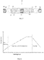
- FIG. 7 is a schematic illustration of an apparatus for continuous production of micro-porous structures according to an embodiment.
- FIG. 8 is a plot illustrating the temperature profiles of three reactor sections of a tunnel furnace according to an embodiment.
- FIGS. 9A-9C are photographs illustrating the morphologies of green tape and porous metal sheet produced according to an embodiment; where FIG. 9A illustrates the green tape, FIG. 9B illustrates a metal sheet produced on the support plate and FIG. 9C illustrates a self-supported thin metal sheet.
- FIGS. 10A and 10B are plots illustrating the tunnel furnace temperature profiles used for conversion of nickel oxide green tapes into porous nickel alloy sheets according to an embodiment.
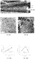
- FIGS. 11A-11C are SEM micrographs illustrating the microstructure at various magnifications of porous metal sheets produced according to an embodiment.
- FIG. 11D is a plot illustrating the surface pore size distribution of the sheet illustrated in FIGS. 11A-11C .
- FIGS. 12A and 12B are photographs illustrating the morphologies of micro-porous ceramic coatings on the thin porous metal sheets according to an embodiment.
- FIGS. 13A-13D are SEM micrographs illustrating structures of a 200 nm YSZ coating on the thin porous metal sheet at different magnifications according to an embodiment.
- FIG. 13D illustrates an elemental mapping of the coating.
- FIGS. 14A and 14B are SEM micrographs of structures of a 50 nm/200 nm YSZ coating on a thin porous metal sheet at different magnifications according to an embodiment.
- FIG. 14B illustrates an elemental mapping of the coating.
- FIGS. 15A-15D are photographs illustrating the conversion of carbon precursor coatings on the porous metal-based supports into micro-porous carbon films according to an embodiment.
- FIGS. 16A-16B are photographs illustrating morphologies of three porous Ni sheet coupons functionalized for carbon nanotube growth according to an embodiment.
- FIGS. 17A-17E are SEM micrographs under different magnification illustrating carbon nanotubes grown inside pores of a porous Ni sheet.
- FIG. 18 is a flow diagram of a method of making porous structures according to an embodiment.
- FIGS. 1-6 show three embodiments of the present invention.
- a green part body 100 comprising particles of metal precursors such as metal oxides, pore formers and organic additives is converted into a porous metallic structure 102 in hydrogen gas environment through the following reactions: Organic additives+ H 2 ⁇ vapor Pore former+ H 2 ⁇ vapor Metal precursor(oxide)+ H 2 ⁇ Metallic grain(solid)+vapor Metallic grains(solid) ⁇ Networked porous structures
- compositions of the green part are illustrated with the green tape cast from slurry comprising metal oxide particles in table 1.
- Particle size distribution of the metal oxide such as nickel oxide used to make the slurry is shown in FIG. 2 .
- the particle size may be in a range of 0.1 to 4 ⁇ m with 50% of the particles below 0.35 ⁇ m and 95% particles below 1.54 ⁇ m.
- FIG. 18 illustrates a flow diagram of an embodiment of a method 1800 of making porous structures from a slurry.
- the metal oxide particles are mixed with a carbon black pore former, dispersant, organic binder, solvent and plasticizer into homogenous slurry in an organic solvent.
- the slurry is cast into a green tape of about 70 ⁇ m thickness, step 1804 .
- the solvent is evaporated during casting to form a nearly dense green tape, step 1806 .
- the non-volatile organic additives and pore formers are removed from the green part into vapor phase by pyrolysis, cracking, and/or hydrogenation reactions. Removal of these constituents in the green part leaves voids or pores 104 in the part.
- the metal precursor such as metal oxide is reduced into metallic grains.
- the gaseous species released from those reactions are swept away by a gas flow. Networked porous structures are formed by controlling the degree of sintering of these metallic grains (step 1810 ).
- the pore size is mainly determined by particle size of the metal precursors.
- fragile precursor materials such as metal oxides
- the particle size over a range of 100 nm to 5 ⁇ m can be produced by milling of bulk powder materials. Metallic materials are too ductile to be milled into such small sizes.
- the pore size in the resulting porous metal structure made from the fragile precursor materials can be smaller than the precursor particle size due to shrinkage of the metal precursor particle.
- the density of nickel oxide is 6.67 g/cc, while the density of nickel metal is 8.89 g/cc.
- the porosity is mainly determined by volume fraction of the pore former in the green part.
- the pore former as a sacrificial material, is preferably in-expensive and removable under the reaction conditions.
- the preferred pore former materials are carbon blacks, polymer particles, and carbonate particles.
- the organic additives including dispersant, binder, and plasticizer, are used to make the metal precursor particle into desired shapes. They are typically organic materials
- Reactivity of the green part 100 can be characterized by thermogravimetric analysis (TGA). Weight changes of four different metal oxide green tapes processed by programmed heating in hydrogen/argon gas flow are shown in FIG. 3 .
- the NiO tape 1 was made of nickel oxide particle and carbon black pore former, while the NiO tape 2 was made of the same nickel oxide but with a carbonate pore former.
- the oxide composite tapes were made of Ni—Fe—Cr mixed oxides and the carbon black pore former.
- the composite tapes 1 and 2 are made of mixed oxides of the same composition but prepared in two different ways. The sample was heated from ambient 25° C. to 650° C. at a ramp rate of 5° C./min and held isothermally at 650° C. for 2 hours.
- the weight loss started at about 220-240° C.
- First stage of rapid weight loss occurred between 320-400° C., which corresponds to pyrolysis of the organic additives and reduction of metal oxides.
- Second stage weight loss started at about 500-600° C., which corresponds to decarbonation.
- the green parts 100 of different compositions show some variation in the extent of weight loss and starting temperature. But, the green parts 100 exhibit common characteristics in removal of some constituents in the green part into vapor phase by chemical reactions.
- the reactivity of the green part 100 can be further delineated by heating the sample inside a furnace with pure hydrogen gas flow.
- FIG. 4 shows evolution of gaseous reaction products, H 2 O, CO 2 , C 2 H 6 , CH 4 , and CO during programmed heating of a nickel oxide green tape in pure hydrogen gas from 20 to 835° C. Peak production of H 2 O, CO 2 , CH 4 and C 2 H 6 occurs in the temperature range of 200 to 400° C., which corresponds to a slight dip in hydrogen signal. H 2 O production is attributed to reduction of nickel oxide. Production of CH 4 and C 2 H 6 results from pyrolysis and cracking of the organic additives. CO 2 formation can be explained by reaction of the organic additive with nickel oxide.
- the second peak production of CH 4 occurs in the range of 550 to 700° C., which results from reaction of hydrogen with the carbon pore former. Small amounts of CO were also produced during the process. Evolution of these gaseous products clearly shows the kinds of chemical reactions involved in decarbonization and deoxygenation of the green part for formation of sintered porous metallic structures.
- the green part 100 is in the form of coating or film 502 supported on a pre-formed porous support structure 504 .
- the coating layer 502 comprises packing of preformed particles/grains 506 with organic additives 508 and/or sintering promoters 510 at a thickness less than 40 ⁇ m.
- the support pore size is about 200 nm to 5 ⁇ m.
- the preformed particles 506 include stable ceramic crystalline materials, such as zirconia, alumina, ceria, and silicon carbide. These preformed particles 506 may be impregnated or doped with some promoter 510 to facilitate sintering of the preformed particle 506 from point-to-point contact to neck-to-neck bonding.
- Organic additives 508 such as dispersants and binders are incorporated into the green part 100 in the coating process.
- the preformed particle size is substantially smaller than the size of the support pores 512 , by a few times to one order of magnitude, to form a membrane layer 514 having membrane pores 516 with pore sizes in the range of 5 to 100 nm.
- the coating layer 502 may be formed by multiple coatings with different particles sizes in an order of decreasing particle size from the support to surface.
- the support structure 504 is intact or experiences minimal changes during the membrane formation process.
- the support structure 504 is preferably made of metallic backbones.
- porous ceramic coatings on a porous ceramic support by high-temperature heating in an oxygen-containing gas environment is known in the membrane field.
- porous zirconia membranes supported on a porous alumina tube can be sintered by heating at above 1000° C. in air.
- sintering of a durable ceramic-type membrane 514 on a metal-based support structure 504 is extremely challenging.
- the metal support structure 504 can be damaged or destroyed by heating above 500° C. in a O 2 -containing gas environment. Even in an inert or reducing gas environment, the porous metallic support structures 504 can experience significant shrinkage at high temperatures.
- a decarbonization and sintering process with controlled temperature gradient and gas environment is provided herein to form a micro-porous ceramic membrane on the preformed metal-based support structure 504 :
- the non-volatile organic additives 508 incorporated in the green part 100 during the coating process are removed into the vapor phase by pyrolysis, decomposition, cracking, and/or hydrogenation.
- the sacrificial material introduced in pre-reforming of the coating particles with addition of the sintering promoter 510 is removed as well during sintering of the grains.
- FIGS. 6A and 6B Additional porous structures may be formed out of a green part 602 comprising dense or less porous material supported on a porous support structure 504 as illustrated in FIGS. 6A and 6B .
- FIG. 6A show conversion of a dense or less porous coating layer 602 on a porous support structure 504 into a networked porous structure 604 through solid/vapor reactions.
- a carbon precursor can be coated on the support structure as a dense or less-porous layer at low temperatures ( ⁇ 100° C.) and may be converted into micro-porous carbon film by chemical reactions at high temperatures (500-900° C.).
- the pores 604 are generated by removing a fraction of the carbon in the green part 602 .
- the carbon precursor material can be phenolic resins and furthermore, thermoset-type phenolic resin, in which oxygen atom in the precursor material can act as an in-situ reactant to generate porous structures.
- CO 2 gas may be added to react with the carbon to form CO.
- H 2 O vapor may be added to react with the carbon to form H 2 and CO.
- Hydrogen gas can be used to react with carbon to form methane.
- micro-porous silicone carbide film or membrane 604 by reacting a functionalized film 602 on the support 504 with carbosilane-type vapor at temperatures of 500-900° C.: Functionalized film/support+Carbosilane ⁇ micro-porous SiC film/support+gaseous by-products
- the carbosilane is a source of C and Si atoms to form silicone carbide.
- the support is functionalized, forming a functionalized coating 602 , to promote, direct, and/or catalyze deposition and reaction of gaseous carbosilane on the support 504 to form a porous silicone carbide film 604 .
- the support 504 can be functionalized by impregnation or coating of alumina of particle sizes less than 100 nm.
- a micro-porous silica membrane or film 604 can be formed by the gas/solid reaction with a vapor-phase precursor containing Si and O atoms: Functionalized support+ Si & O precursor ⁇ micro-porous silica film/support+gaseous by-products
- the Si and O-containing precursor examples include vinyltriethoxysilane (VTES) and tetraethoxyorthosilicate (TEOS).
- VTES vinyltriethoxysilane
- TEOS tetraethoxyorthosilicate
- the support can be functionalized by coatings of alumina of particle size less than 100 nm. A small fraction of Ni, Fe, and/or Co may be added into the coating.
- the new porous structures can be formed inside the pores of a porous support structure.
- surface of the metallic grains inside a porous metal-based support structure may be functionalized, such as by deposition of a catalyst to form a functionalized support 606 .
- a gas reactant diffuses into the pores 512 of the support to form new structures 600 .
- Such a process is illustrated with growth of carbon nanotubes inside the support pores: Functionalized support+Carbon precursor ⁇ Carbon nanotubes+gaseous by-products
- the metal-based porous support can be functionalized by deposition of transition metal catalysts, such as Fe, Ni, and/or Co, on the surface of metallic grains inside the support.
- the carbon precursor can be, but is not limited to, CO, methane, ethanol, ethane or ethylene in an inert carrier gas such as nitrogen.
- the chemical vapor deposition or gas/solid reaction may be carried out at temperatures from 500 to 900° C.
- the common features of above-described formation processes of micro-porous structures are i) reaction of gaseous reactant with the green part at high temperatures (500 to 1200° C.), ii) evolution of gaseous byproducts, and iii) reducing or inert gas environment with substantial absence of oxygen gas.
- the reaction temperature should be well controlled to achieve the designed level of reaction conversion.
- the gaseous reactant should be constantly supplied and the gaseous byproducts should be constantly removed. Therefore, a continuous production process is presented by this embodiment to produce the porous structures economically at large scales.
- the porous structures can be in various forms or shapes, such as sheets, tubes, and monoliths. A flat sheet form is preferred, because its simple geometry renders high throughput handling.
- the sheet thickness is preferably thin, less than 1 mm or less than 200 ⁇ m.
- the thinness of the sheet reduces diffusion mass transfer resistance and increases stacking density of the sheets.
- the basic functional units of a continuous production system 700 are shown in FIG. 7 .
- the green parts 100 located on supports 504 are fed into an inlet gas exchange chamber 702 where oxygen or air entrained into the chamber is removed, such as by sweep with an inert gas.
- the green parts 100 are moved into a preheating section 708 via a gas-tight connector 704 .
- volatile or thermally-unstable constituents in the green parts are removed via an exhaust outlet 706 .
- the green parts 504 are moved into a reaction and sintering section 710 where the green parts 504 react with a gas flow, provided via a gas inlet 714 , to form product parts 718 of desired porous structures.
- the product parts 718 are moved into cooling section 712 .
- the product parts 718 are moved into an outlet gas exchange chamber 716 where the reactive gas entrained by the product parts 718 are removed, such as by sweep with inert nitrogen gas.
- the green parts 100 are continuously fed while the product parts 718 are continuously moved out.
- the reactive gas is continuously introduced into the reaction and sintering section 710 to purge the gaseous products out of the furnace and supply the reactant to react with the green part 100 , while the reacted gas stream is continuously discharged.
- the feed gas may be introduced at different locations or sections, while the reacted gas may be discharged at different locations or section.
- the feed gas may be introduced at the cooling section 712 , reaction and sintering section 710 , and the preheating section 708 to meet specific needs to the gas flow rate and compositions in respective sections 708 , 710 , 712 .
- the gas flow direction is preferably opposite to the moving direction of the green parts 100 .
- the feed gas composition is determined by specific reaction conversion need.
- conversion of the green parts to the product parts 718 is limited by hydrogen reaction, pure hydrogen is used. If the conversion requires a small fraction of active reactants, such as CO 2 , H 2 O, CO, ethanol, CH 4 , carbosilane, or TEOS, an inert carrier gas, such as nitrogen, argon and Helium, can be used.
- active reactants such as CO 2 , H 2 O, CO, ethanol, CH 4 , carbosilane, or TEOS
- an inert carrier gas such as nitrogen, argon and Helium.
- the feed gas should be substantially free of oxidants, such as oxygen, to protect the formed porous structure 718 from being oxidized.
- the preheating 708 , reaction and sintering 710 , and cooling sections 712 may be built as mutually-connected individual sections or as different zones in one reactor body.
- the three sections are controlled with different temperature profiles.
- the green part 100 is heated from ambient temperature to moderate temperatures such as 200-400° C. in the preheating zone 708 .
- the reaction and sintering zone 710 the green part 100 may be heated to and held at much higher temperatures.
- the temperature is as high as 1000-1300° C. for formation of micro-porous stainless-steel structures.
- the temperature required for formation of porous nickel and nickel alloy is about 750 to 900° C.
- the temperature is about 700 to 1100° C.
- the temperature is about 500 to 900° C.
- the reaction and sintering section 710 should have sufficiently high aspect ratio to control the temperature profile.
- the aspect ratio is defined as ratio of the reactor length to width of the reaction tunnel or diameter for a rounded reaction channel. The aspect ratio is preferably greater than 2.
- a green tape comprising nickel oxide particles was converted into thin porous Ni alloy sheets in a continuous tunnel flow reactor.
- the green tape thickness was about 70 ⁇ m with the composition listed in Table 1.
- the thin green tape 900 is flexible enough to be wrapped on a roller 902 .
- the green tape 900 was cut into 35 cm ⁇ 35 cm coupons and set on a durable substrate plate to be processed in a tunnel flow reactor or environment-controlled tunnel furnace.
- the tunnel furnace temperature was maintained by use of many independently-controlled electrical heaters along the furnace length.
- FIG. 10 shows the temperature profiles in the three sections. In the pre-heating section ( FIG. 10A ), the temperature was gradually increased to 400° C. through nine heating zones. In the reaction section ( FIG. 10B ), the temperature was raised from 400° C.
- the temperature in lower and upper points of the tunnel were maintained almost the same to achieve uniform de-gas, reaction, and sintering over the cross-section of the tunnel.
- the green tapes 900 were continuously moved through the tunnel and experienced significant temperature variance along the tunnel length.
- the de-gas, reaction, and sintering rates should be well controlled and balanced to prevent formation of defects, such as cracks, wrinkling, and pinholes.
- the temperature gradient among two heating zones can be much greater in the cooling section than in the preheating 708 and reaction sintering 710 sections.
- Pure hydrogen gas was introduced into the reactor tunnel at end of the cooling section and discharged at the beginning of the preheating section 708 , i.e., the hydrogen flow direction was opposite to the green part movement. After the desired temperature profiles and hydrogen gas flow were stabilized, stacks of the green tapes were pushed into the preheating section 708 and pushed out of the cooling section 712 continuously one by one.
- FIG. 9B shows a thin porous Ni alloy sheet 718 produced from the continuous furnace.
- the thin sheet 718 was laid on a rigid and stable substrate plate.
- the sheet 718 looked flat and free of any defects.
- the thin metal sheet 718 presents much higher strength than the green tape 502 .
- FIG. 9C shows that the porous metal sheet 718 is strong enough to be self-supported. No light penetration or pin-holes are seen on the sheet 718 . Any holes that allow the light to go through indicate that the hole is too large.
- the stacks of green tapes 502 are fed into the tunnel reactor one by one or stack by stack. Sizes and porosity of a few consecutive stacks processed under the same conditions are summarized in table 2.
- the average thickness and porosity of these stacks listed in Table 2 are 46 ⁇ 2 ⁇ m and 40 ⁇ 3%, respectively. These variances are acceptable to most practical applications.
- FIGS. 11A-C show scanning electron microscope (SEM) images under different magnification.
- SEM scanning electron microscope
- FIG. 11A shows a smooth surface is seen, and pores are not visible yet.
- FIG. 11B magnification, the porous structure and surface features become evident.
- the image at 5000 ⁇ magnification shows neck-to-neck sintering of metallic grains, pores or voids formed among the grains, and some carbon residuals.
- the porous surface structure looks uniform and no pore size greater than 5 ⁇ m are seen.
- FIG. 11D shows the surface pore size distribution of two representative porous Ni alloy sheets produced in this embodiment.
- Example II Sintering of Micro-Porous Ceramic Coating on the Porous Metal Sheet Support
- Two porous Ni alloy sheets produced from the continuous hydrogen furnace with respective thicknesses of 49 ⁇ 1.6 ⁇ m and 47 ⁇ 1.3 ⁇ m were used as a support structure 504 . They were cut into 3.5 cm ⁇ 5.5 cm coupons for preparation of porous ceramic membranes of pore sizes much smaller than the support.
- the ceramic particles were coated on a 3.0 cm ⁇ 5.0 cm area of the coupon by vacuum filtration of a coating slurry.
- the ceramic particle used for first layer coating was yttria-stabilized zirconia (YSZ) of 200 nm mean particle size.
- the YSZ particle was impregnated with 1.1 wt. % nickel oxide as a sintering promoter.
- the 1 st coating slurry included 0.5 wt.
- the slurry volume used for the first layer of coating is listed in table 3.
- the metal surface was fully covered by first coating to form a smooth, uniform coating layer.
- second coating with 50 nm YSZ particles was applied.
- the second coating slurry included 0.25 wt. % of the 50 nm YSZ particle, 0.006 wt. % of the dispersant and 0.006 wt. % of the binder.
- the volume of the coating solution used is listed in table 3. The coated samples were dried in ambient air conditions.
- the amount of coating is normalized by the coated area as surface loading density, mg/cm 2 .
- the as-coated layer comprising stacking of the YSZ particles, was very loose such that it could be easily wiped or rinsed away from the support sheet. It should be sintered to form a stable structure.
- the ceramic coating layer adhered to the porous Ni support sheet as an integrated body.
- the sintered membrane was soaked in a 50 wt. % KOH solution and no crack occurred. Electrical conductivity of the ceramic coating was tested. The results show that the coating layer does not present any electrical conductivity when its thickness is at about or above 10 ⁇ m, which suggests that the metallic surface was fully insulated by the ceramic coating.
- YSZ is a refractory material. Formation of porous YSZ membranes on a ceramic support typically requires sintering temperatures above 1000° C. in air or oxygen-containing gas environment. It has been very difficult to sinter YSZ coatings on a porous metal support structure due to the limitation of the metallic material properties. In an oxygen-containing gas environment, the metallic structure would be oxidized and destroyed at high temperatures. Even in an oxygen-free gas environment, the metallic structure can experience dramatic shrinkage when heated at high temperatures, which would result in cracks and/or delamination of the ceramic coating layer. This example demonstrates the feasibility to prepare thin ( ⁇ 40 ⁇ m) porous ceramic membranes or coatings on the porous metal-based support structures through reactive processes under controlled temperature and gas flow profiles in a continuous reactor system.
- the YSZ coating dramatically reduces surface pore sizes.
- Micro-structures of the porous metal sheet coated with the 200 nm YSZ particles are shown in FIGS. 13A-C at different magnification (2,500; 15,000; 50,000).
- the YSZ coating surface looks much smoother and comprises pores in the tens of nm.
- the surface pore size is reduced by about an order of magnitude relative to the pores in the metal sheets.
- FIG. 13C shows that the neck-to-neck sintering of the YSZ crystalline grains occurred.
- Uniform distribution of the promoter (NiO) is revealed by elemental mapping of Zr, Ni, and Y in FIG.
- FIG. 13D (5,000 ⁇ magnification). No segregated NiO phase was found.
- the surface pore size was further reduced by applying the 50 nm YSZ coating on the 200 nm coating.
- FIG. 14A (50,000 ⁇ magnification) shows that large pores between the 200 nm crystalline grains were substantially filled by the 50 nm YSZ crystalline and finer surface pores were formed.
- the elemental mapping at 5000 ⁇ magnification in FIG. 14B also confirms uniform distribution of Zr, Y, and Ni elements.
- the NiO promoter was incorporated into the YSZ crystalline after sintering.
- Example III Formation of Micro-Porous Carbon Coating on the Thin Metal Sheet-Based Support
- the carbon precursor was coated on the porous Ni sheet support by vacuum filtration.
- the coating material and loading density for four samples are listed in Table 4.
- the support sheet was cut into 3.5 cm ⁇ 5.5 cm coupons. The coating was deposited on the coupon in 3 cm ⁇ 5 cm region.
- phenol-formaldehyde thermosetting (PFT) resin solution in ethanol was used.
- the 50 nm/200 nm YSZ-coated porous Ni sheet was as used for sample 1 and the bare porous Ni sheet of about 50 ⁇ m thickness was used for sample 2 to see the impact of the support surface on formation of micro-porous carbon membranes.
- the phenol-formaldehyde thermoplastic resin (PFTP) solution in ethanol was used for samples 3 and 4.
- the support used for sample 3 was the porous Ni sheet grown with a NaA-type zeolite membrane.
- the bare Ni sheet was used as a support for sample 4.
- the coated sample was dried to remove all the solvent and volatile component.
- the surface loading density of the carbon precursor, i.e., phenol-formaldehyde resin, is listed in Table 3.
- the dried samples were loaded into a tunnel reactor with continuous nitrogen gas flow. The samples were heated from room temperature to 700° C. and held at 700° C. for 1 h to remove oxygen and a fraction of carbon from the carbon precursor, and to form micro-porous carbon structures.
- the last column in Table 4 shows that weight loss of the coating material was greater than 50% for all the samples.
- the morphology changes are shown in FIG. 15 .
- the example demonstrates the feasibility to form new micro-porous structures from a dense or less porous coating precursor on the porous metal support structure by reaction in flowing gas under a certain temperature profile.
- Example IV Formation of Micro-Porous Structures Inside Pores of a Porous Metal Support
- a porous Ni sheet of about 50 ⁇ m thickness was used as a support.
- Three support coupons were impregnated with 0.1M iron nitrate, cobalt nitrate, and Ni nitrate solutions, respectively. After drying, the metallic grains inside pores of the three metal support sheets were functionalized by respective Fe, Co, and Ni catalyst.
- the functionalized coupons were placed inside a tunnel reactor. The reactor was first purged by nitrogen gas flow and then by hydrogen gas flow. The reactor was heated to 650° C. in continuous hydrogen gas flow. At 650° C., the hydrogen gas flow was switched to ethanol/nitrogen gas flow. The sample was exposed to the ethanol/nitrogen gas flow for about 10 min. Carbon nanotubes (CNT) were grown inside the pores of the metal support sheet.
- FIGS. 17A and 17B show the surface textures of the porous Ni sheet with CNT grown on the Fe catalyst seeding (sample 1 in FIG. 16B ) under 3,000 and 20,000 ⁇ magnification, respectively. It can be seen that the pores of the nickel support sheet remained intact, but CNT features were added inside the pores.
- FIG. 17C shows the surface texture of the porous Ni sheet with CNT grown on the Co seeding (sample 2 in FIG. 16B ) under 30,000 ⁇ magnification.
- the Ni catalyst promoted growth of CNT of smaller diameter (30-50 nm).
- the analysis of the fractured wall confirmed growth of the CNT throughout the support sheet thickness.
- FIGS. 17D, 17E show the fractured porous Ni sheet wall with CNT growth on the Ni sheet (sample 3 in FIG. 16B ) under 1,600 and 20,000 ⁇ magnification, respectively.
- This example demonstrates the feasibility to grown smaller porous structures inside the pore of a porous metal support structure through gas/solid reactions in continuous gas flow.
- An electrically controlled process for producing microperforated stainless steel which comprises connecting a sheet of stainless steel having a thickness between approximately 0.0005′′ and 0.005′′, containing intergranular iron chromium precipitates and containing as essential elements a preponderance of iron and a lesser but significant amount of chromium as the anode in an electrolytic cell having a non-polarizing electrolyte and a cathode and discharging direct current through said cell so as to anodically dissolve intergranular iron chromium precipitates in said sheet and to thereby produce a multiplicity of light transmitting microperforations through said sheet, the microperforations being primarily due to electrochemical action.
- a porous product typically a metal foam sheet
- an engineered product can be produced which, for example, as an open-cell metal foam prepared from a polymeric foam can have conductivity, both thermal and electrical, as well as strength and ductility, tailored for greater uniformity and performance.
- a method of manufacturing a porous metal sheet having pores forming a pattern comprising the steps of supplying metal powders to a peripheral surface, of at least one pattern roller of a pair of rollers, on which a pattern including a large number of concaves is formed; dropping metal powders to the concaves and accumulating metal powders on the peripheral surface of the pattern roller except the concaves; and rolling directly the metal powders accumulated on the peripheral surface of the pattern roller by rotating a pair of the rollers. It is preferable to laminate porous metal sheets or solid metal sheets manufactured by a method other than the above-described method on the metal sheet manufactured by the above-described method.
- the utility model relates to a horizontal continuous annealing furnace for annealing titanium strips and steel strips.
- the horizontal continuous annealing furnace comprises a heating section, a transition section and a cooling section, wherein sealing systems are respectively arranged before the heating section and after the cooling section, and a protective atmosphere in all sections of the furnace is communicated;
- the horizontal continuous annealing furnace can be used for continuous annealing of the titanium strips and the steel strips so as to obtain the annealed titanium strips and the steel strips with uniform structures and performances and good surface quality.
- a seal assembly located at an entrance or exit of a heat treatment furnace for heat treating a continuously fed metallic strip using an atmospheric gas containing hydrogen gas as a furnace gas and including an elastic rotating roll which is engaged with an elastic pad fixed on a surface of a seal plate and the metallic strip to seal an inside of the furnace against outside air, wherein elastic members are provided in through-holes formed through a side plate of a furnace wall at positions corresponding to both side edges of the elastic pad and elastic member-moving mechanisms are provided for engaging the elastic members with the sides of the elastic pad.
Landscapes
- Chemical & Material Sciences (AREA)
- Engineering & Computer Science (AREA)
- Mechanical Engineering (AREA)
- Chemical Kinetics & Catalysis (AREA)
- Organic Chemistry (AREA)
- Metallurgy (AREA)
- Materials Engineering (AREA)
- Manufacturing & Machinery (AREA)
- Inorganic Chemistry (AREA)
- General Chemical & Material Sciences (AREA)
- Health & Medical Sciences (AREA)
- General Engineering & Computer Science (AREA)
- Clinical Laboratory Science (AREA)
- Separation Using Semi-Permeable Membranes (AREA)
- Powder Metallurgy (AREA)
Abstract
Description
Organic additives+H 2→vapor
Pore former+H 2→vapor
Metal precursor(oxide)+H 2→Metallic grain(solid)+vapor
Metallic grains(solid)→Networked porous structures
| TABLE 1 |
| Typical composition of green tapes |
| Wet slurry tape, Wt. % | Tape dried, Vol. % | ||
| Metal oxide | 52 | 33 | ||
| Pore former | 14 | 33 | ||
| Solvent | 25 | 0 | ||
| |
1 | 4 | ||
| |
5 | 18 | ||
| |
3 | 12 | ||
Organic additives+H 2→vapor
Packed particles or grains(+promoter)+H 2→Vapor+sintered grains
The carbon precursor+gas→porous carbon+gaseous by-products
Functionalized film/support+Carbosilane→micro-porousSiC film/support+gaseous by-products
Functionalized support+Si&O precursor→micro-porous silica film/support+gaseous by-products
Functionalized support+Carbon precursor→Carbon nanotubes+gaseous by-products
| TABLE 2 |
| Porous thin Ni sheets produced by a continuous process |
| Stack | Width, cm | Thickness, μm | Geometric |
| # | Avg. | STDEV | Avg. | STDEV | Porosity | ||
| 1-2 | 23.7 | 0.1 | 44 | 3 | 0.44 | ||
| 1-3 | 23.3 | 0.1 | 45 | 2 | 0.43 | ||
| 1-4 | 23.4 | 0.3 | 44 | 2 | 0.41 | ||
| 1-5 | 23.4 | 0.2 | 45 | 3 | 0.43 | ||
| 1-6 | 23.7 | 0.1 | 44 | 1 | 0.43 | ||
| 2-1 | 23.9 | 0.3 | 44 | 1 | 0.43 | ||
| 2-2 | 23.4 | 0.2 | 46 | 2 | 0.43 | ||
| 2-3 | 23.5 | 0.2 | 43 | 2 | 0.43 | ||
| 2-4 | 23.4 | 0.1 | 44 | 1 | 0.42 | ||
| 2-5 | 23.5 | 0.1 | 44 | 2 | 0.42 | ||
| 2-6 | 23.4 | 0.2 | 47 | 2 | 0.44 | ||
| 3-1 | 23.7 | 0.1 | 46 | 2 | 0.45 | ||
| 3-2 | 23.2 | 0.3 | 45 | 1 | 0.41 | ||
| 3-3 | 23.1 | 0.1 | 44 | 2 | 0.40 | ||
| 3-4 | 23.3 | 0.1 | 45 | 1 | 0.41 | ||
| 3-5 | 23.5 | 0.1 | 45 | 3 | 0.42 | ||
| 3-6 | 23.5 | 0.1 | 45 | 2 | 0.42 | ||
| 5-1 | 23.0 | 0.2 | 44 | 2 | 0.38 | ||
| 5-2 | 22.5 | 0.2 | 44 | 2 | 0.36 | ||
| 5-3 | 22.5 | 0.2 | 46 | 1 | 0.38 | ||
| 5-4 | 22.6 | 0.2 | 44 | 2 | 0.36 | ||
| 5-5 | 22.6 | 0.1 | 45 | 2 | 0.38 | ||
| 5-6 | 22.5 | 0.1 | 46 | 2 | 0.37 | ||
| 5-7 | 22.4 | 0.1 | 45 | 0 | 0.36 | ||
| 5-8 | 22.5 | 0.1 | 47 | 3 | 0.38 | ||
| 6-1 | 23.0 | 0.2 | 44 | 2 | 0.38 | ||
| 6-2 | 22.4 | 0.1 | 47 | 1 | 0.37 | ||
| 6-3 | 22.3 | 0.1 | 47 | 2 | 0.37 | ||
| 6-4 | 22.4 | 0.1 | 48 | 2 | 0.39 | ||
| 6-5 | 22.6 | 0.2 | 47 | 2 | 0.39 | ||
| 6-6 | 22.4 | 0.2 | 47 | 2 | 0.38 | ||
| 6-7 | 22.5 | 0.2 | 47 | 1 | 0.38 | ||
| 6-8 | 22.6 | 0.1 | 46 | 2 | 0.37 | ||
| 8-1 | 23.5 | 0.1 | 48 | 1 | 0.44 | ||
| 8-2 | 23.0 | 0.2 | 49 | 3 | 0.43 | ||
| 8-3 | 22.8 | 0.1 | 47 | 2 | 0.40 | ||
| 8-4 | 22.8 | 0.2 | 49 | 1 | 0.42 | ||
| 8-5 | 22.8 | 0.1 | 47 | 2 | 0.40 | ||
| 8-6 | 22.8 | 0.4 | 46 | 1 | 0.38 | ||
| 9-1 | 23.5 | 0.4 | 47 | 2 | 0.42 | ||
| 9-2 | 22.8 | 0.2 | 46 | 3 | 0.38 | ||
| 9-3 | 22.6 | 0.2 | 47 | 3 | 0.38 | ||
| 9-4 | 22.6 | 0.2 | 50 | 3 | 0.42 | ||
| 9-5 | 22.7 | 0.2 | 48 | 3 | 0.41 | ||
| 9-6 | 22.8 | 0.2 | 49 | 3 | 0.42 | ||
| 10-1 | 23.6 | 0.3 | 48 | 2 | 0.44 | ||
| 10-2 | 22.9 | 0.3 | 49 | 1 | 0.41 | ||
| 10-3 | 22.6 | 0.2 | 49 | 4 | 0.40 | ||
| 10-4 | 22.6 | 0.2 | 50 | 3 | 0.41 | ||
| 10-5 | 22.5 | 0.2 | 48 | 2 | 0.37 | ||
| 10-6 | 22.6 | 0.1 | 47 | 2 | 0.39 | ||
| TABLE 3 |
| Micro-porous ceramic membranes supported on the thin |
| porous |
| Metal |
| 1st | 2nd | Coating | Elec- | ||||
| sheet | coating | coating | thickness | trical | |||
| thick- | slurry | slurry | Coating | after | con- | ||
| ID | ness, | Porosity, | usage, | usage, | loading, | sintering, | duc- |
| No. | μm | % | ml | ml | mg/cm2 | μm | |
| 1 | 49 | 42 | 3 | No | 1.05 | | NA | |
| 2 | 49 | 45 | 3 | 1 | 0.64 | 9 | |
|
| 3 | 49 | 47 | 3 | 1 | 0.79 | 2 | |
|
| 4 | 49 | 45 | 3 | 1 | 0.77 | 3 | |
|
| 5 | 49 | 47 | 6 | 2 | 1.57 | | NA | |
| 6 | 49 | 43 | 6 | 1.67 | 5 | |
||
| 7 | 49 | 44 | 6 | 2 | 1.61 | 5 | |
|
| 8 | 49 | 44 | 5 | 2 | 1.82 | 6 | |
|
| 9 | 49 | 42 | 10 | 4 | 3.58 | 20 | |
|
| 10 | 47 | 43 | 10 | 4 | 3.24 | 23 | |
|
| 11 | 47 | 43 | 10 | 4 | 3.12 | 11 | |
|
| 12 | 47 | 43 | 10 | 4 | 4.17 | 15 | |
|
| 13 | 47 | 41 | 10 | 4 | 3.18 | NA | NA | |
| NA = not measured. | ||||||||
| TABLE 4 |
| Carbon coating on porous metal support sheet |
| Overall | |||||||
| coating | Coating | ||||||
| thick- | density | Carbon | |||||
| ness | of | precursor | Carbon | ||||
| on | carbon | loading, | coating | ||||
| Sam- | the metal | pre- | wt. % of | weight | |||
| ple | Coating | sheet, | cursor, | support | loss, | ||
| No. | solution | Support | μm | mg/cm2 | | wt. % | |
| 1 | 35 ml, 2 | 50 | 39 | 0.7 | 1.9% | −65% | |
| wt.% of | nm/200 NM | ||||||
| PFT | YSZ-coated | ||||||
| |
|||||||
| 2 | 3 ml of 20 | Bare Ni | 27 | 1.1 | 2.4% | −63% | |
| wt. % | Sheet | ||||||
| of |
|||||||
| 3 | 35 ml of | NaA-type | 17 | 0.4 | 1.0% | −54% | |
| 2 wt. | zeolite | ||||||
| % of | grown | ||||||
| PFTP | on the | ||||||
| sheet | |||||||
| 4 | 35 ml of 2 | |
13 | 0.9 | 2.2% | −83% | |
| wt. % of | Sheet | ||||||
| PFTP | |||||||
Claims (19)
Priority Applications (3)
| Application Number | Priority Date | Filing Date | Title |
|---|---|---|---|
| US16/235,178 US11486030B2 (en) | 2018-05-23 | 2018-12-28 | Process and apparatus for continuous production of porous structures |
| CN201910317947.8A CN110523295B (en) | 2018-05-23 | 2019-04-19 | Continuous production process and apparatus for porous structure |
| US17/943,680 US20230051729A1 (en) | 2018-05-23 | 2022-09-13 | Process and Apparatus for Continuous Production of Porous Structures |
Applications Claiming Priority (2)
| Application Number | Priority Date | Filing Date | Title |
|---|---|---|---|
| US201862675341P | 2018-05-23 | 2018-05-23 | |
| US16/235,178 US11486030B2 (en) | 2018-05-23 | 2018-12-28 | Process and apparatus for continuous production of porous structures |
Related Child Applications (1)
| Application Number | Title | Priority Date | Filing Date |
|---|---|---|---|
| US17/943,680 Division US20230051729A1 (en) | 2018-05-23 | 2022-09-13 | Process and Apparatus for Continuous Production of Porous Structures |
Publications (2)
| Publication Number | Publication Date |
|---|---|
| US20190358706A1 US20190358706A1 (en) | 2019-11-28 |
| US11486030B2 true US11486030B2 (en) | 2022-11-01 |
Family
ID=68614942
Family Applications (2)
| Application Number | Title | Priority Date | Filing Date |
|---|---|---|---|
| US16/235,178 Active 2040-07-02 US11486030B2 (en) | 2018-05-23 | 2018-12-28 | Process and apparatus for continuous production of porous structures |
| US17/943,680 Pending US20230051729A1 (en) | 2018-05-23 | 2022-09-13 | Process and Apparatus for Continuous Production of Porous Structures |
Family Applications After (1)
| Application Number | Title | Priority Date | Filing Date |
|---|---|---|---|
| US17/943,680 Pending US20230051729A1 (en) | 2018-05-23 | 2022-09-13 | Process and Apparatus for Continuous Production of Porous Structures |
Country Status (2)
| Country | Link |
|---|---|
| US (2) | US11486030B2 (en) |
| CN (1) | CN110523295B (en) |
Citations (11)
| Publication number | Priority date | Publication date | Assignee | Title |
|---|---|---|---|---|
| US3352769A (en) | 1967-01-11 | 1967-11-14 | Ruben Samuel | Process for producing microperforated stainless steel sheets |
| US3668024A (en) * | 1969-10-07 | 1972-06-06 | Smith Inland A O | Method of annealing metal powder |
| US3677721A (en) * | 1970-12-07 | 1972-07-18 | Union Carbide Corp | Porous metal bodies of uniform porosity |
| US3871829A (en) * | 1972-10-20 | 1975-03-18 | Gen Electric | Calciner with baffle means |
| EP0311030A1 (en) | 1987-10-07 | 1989-04-12 | Linde Aktiengesellschaft | Process for annealing metallic work pieces in a continuous furnace |
| US5693288A (en) | 1994-06-24 | 1997-12-02 | Nisshin Steel Co., Ltd. | Seal assembly for thermal treatment furnaces using an atmospheric gas containing hydrogen gas |
| US5738907A (en) | 1995-08-04 | 1998-04-14 | Eltech Systems Corporation | Conductive metal porous sheet production |
| US5850591A (en) | 1996-04-19 | 1998-12-15 | Katayama Special Industries, Ltd. | Method of manufacturing a metal sheet |
| US20070128568A1 (en) * | 2005-12-07 | 2007-06-07 | Ajax Tocco Magnethermic Corporation | Method and apparatus to provide continuous movement through a furnace |
| CN203569154U (en) | 2013-11-08 | 2014-04-30 | 中冶南方(武汉)威仕工业炉有限公司 | Horizontal continuous annealing furnace for annealing titanium belt and steel belt |
| CN104004888A (en) * | 2014-05-14 | 2014-08-27 | 中国科学院广州能源研究所 | Continuous annealing device for thermochromatic coating materials on sheet substrates |
Family Cites Families (11)
| Publication number | Priority date | Publication date | Assignee | Title |
|---|---|---|---|---|
| US3671228A (en) * | 1969-10-30 | 1972-06-20 | Battelle Development Corp | Method of making high-density sintered metal |
| GB8914023D0 (en) * | 1989-06-19 | 1989-08-09 | Alcan Int Ltd | Porous ceramic membrane method |
| JPH03260591A (en) * | 1990-03-08 | 1991-11-20 | O S Seramu Kk | Continuous sintering furnace |
| JPH1143705A (en) * | 1997-07-24 | 1999-02-16 | Mitsubishi Materials Corp | Continuous firing method and continuous firing device for long plate |
| JP2002512308A (en) * | 1998-04-17 | 2002-04-23 | ゲーカーエヌ・ジンター・メタルス・ゲゼルシャフト・ミト・ベシュレンクテル・ハフツング | Method for producing thin metal layer with open porosity |
| US7476636B2 (en) * | 2004-12-03 | 2009-01-13 | L'air Liquide, Societe Anonyme A Directoire Et Conseil De Surveillance Pour L'etude Et L'exploration Des Procedes Georges Claude | Method of making mixed matrix membranes using electrostatically stabilized suspensions |
| US9079136B2 (en) * | 2009-05-21 | 2015-07-14 | Battelle Memorial Institute | Thin, porous metal sheets and methods for making the same |
| RU2424083C1 (en) * | 2009-12-28 | 2011-07-20 | Федеральное государственное унитарное предприятие "Красная звезда" | Method of producing filtration material |
| CN102881930A (en) * | 2012-10-26 | 2013-01-16 | 中国科学院上海硅酸盐研究所 | Method for preparing flat-plate type metal-support solid oxide fuel cell |
| CN103115487B (en) * | 2013-01-23 | 2014-12-24 | 青海拓海新材料有限公司 | Tunnel kiln producing silicon nitride and silicon carbide combined product with nitrogen discharged by entrained-flow bed reactor |
| CN106621800B (en) * | 2016-12-26 | 2023-11-24 | 重庆稳稳科技有限公司 | Moving bed hot sinter denitration device |
-
2018
- 2018-12-28 US US16/235,178 patent/US11486030B2/en active Active
-
2019
- 2019-04-19 CN CN201910317947.8A patent/CN110523295B/en active Active
-
2022
- 2022-09-13 US US17/943,680 patent/US20230051729A1/en active Pending
Patent Citations (11)
| Publication number | Priority date | Publication date | Assignee | Title |
|---|---|---|---|---|
| US3352769A (en) | 1967-01-11 | 1967-11-14 | Ruben Samuel | Process for producing microperforated stainless steel sheets |
| US3668024A (en) * | 1969-10-07 | 1972-06-06 | Smith Inland A O | Method of annealing metal powder |
| US3677721A (en) * | 1970-12-07 | 1972-07-18 | Union Carbide Corp | Porous metal bodies of uniform porosity |
| US3871829A (en) * | 1972-10-20 | 1975-03-18 | Gen Electric | Calciner with baffle means |
| EP0311030A1 (en) | 1987-10-07 | 1989-04-12 | Linde Aktiengesellschaft | Process for annealing metallic work pieces in a continuous furnace |
| US5693288A (en) | 1994-06-24 | 1997-12-02 | Nisshin Steel Co., Ltd. | Seal assembly for thermal treatment furnaces using an atmospheric gas containing hydrogen gas |
| US5738907A (en) | 1995-08-04 | 1998-04-14 | Eltech Systems Corporation | Conductive metal porous sheet production |
| US5850591A (en) | 1996-04-19 | 1998-12-15 | Katayama Special Industries, Ltd. | Method of manufacturing a metal sheet |
| US20070128568A1 (en) * | 2005-12-07 | 2007-06-07 | Ajax Tocco Magnethermic Corporation | Method and apparatus to provide continuous movement through a furnace |
| CN203569154U (en) | 2013-11-08 | 2014-04-30 | 中冶南方(武汉)威仕工业炉有限公司 | Horizontal continuous annealing furnace for annealing titanium belt and steel belt |
| CN104004888A (en) * | 2014-05-14 | 2014-08-27 | 中国科学院广州能源研究所 | Continuous annealing device for thermochromatic coating materials on sheet substrates |
Non-Patent Citations (1)
| Title |
|---|
| Machine translation of CN-104004888-A, retrieved Jul. 6, 2021. * |
Also Published As
| Publication number | Publication date |
|---|---|
| CN110523295A (en) | 2019-12-03 |
| CN110523295B (en) | 2021-10-08 |
| US20190358706A1 (en) | 2019-11-28 |
| US20230051729A1 (en) | 2023-02-16 |
Similar Documents
| Publication | Publication Date | Title |
|---|---|---|
| Nam et al. | Hydrogen separation by Pd alloy composite membranes: introduction of diffusion barrier | |
| US9079136B2 (en) | Thin, porous metal sheets and methods for making the same | |
| JPWO2007015550A1 (en) | Silicon carbide firing jig and method for producing porous silicon carbide body | |
| JP4051569B2 (en) | Method for producing intermetallic compound porous material | |
| JP4885159B2 (en) | Oxygen separation membrane element | |
| JP2008237945A (en) | Hydrogen separation membrane | |
| CN107838427B (en) | Porous sintered metal composite film and preparation method thereof | |
| US20230051729A1 (en) | Process and Apparatus for Continuous Production of Porous Structures | |
| JP5031616B2 (en) | Oxygen separator and method for producing the same | |
| JP2007000858A (en) | Hydrogen permeation member and its manufacturing method | |
| JPS63171802A (en) | Prodoction of porous sintered metallic body | |
| CN118434500A (en) | Gas handling body of structure for carbon capture | |
| JP2005081246A (en) | Oxygen separation membrane element and manufacturing method thereof | |
| JPH05285357A (en) | Membrane for separation of hydrogen | |
| JP2003190792A (en) | Catalytic ceramic composite and synthesis gas production method | |
| JP6493669B2 (en) | Method for producing paper-like catalyst structure for hydrogen production | |
| US7387755B2 (en) | Method of making a ceramic composite | |
| FR2969012A1 (en) | CATALYST COMPRISING ACTIVE PARTICLES BLOCKED PHYSICALLY ON THE SUPPORT | |
| JP2003135943A (en) | Hydrogen separation membrane and method for producing hydrogen separation membrane | |
| JP2006082039A (en) | Oxygen separation membrane element, its production method, oxygen production method, and reactor | |
| JP5512374B2 (en) | Method for producing catalyst carrier by plasma spraying and catalyst carrier | |
| CN113398662A (en) | Laminated filter medium for high-temperature gas filtering and dust removing device and preparation method thereof | |
| JP2005279439A (en) | Oxygen separation membrane element, oxygen production method, and reactor | |
| CN113769483B (en) | Laminated porous ceramic filter material for high-temperature gas purification and preparation method thereof | |
| JP5057684B2 (en) | Hydrogen production equipment |
Legal Events
| Date | Code | Title | Description |
|---|---|---|---|
| FEPP | Fee payment procedure |
Free format text: ENTITY STATUS SET TO UNDISCOUNTED (ORIGINAL EVENT CODE: BIG.); ENTITY STATUS OF PATENT OWNER: SMALL ENTITY |
|
| FEPP | Fee payment procedure |
Free format text: ENTITY STATUS SET TO SMALL (ORIGINAL EVENT CODE: SMAL); ENTITY STATUS OF PATENT OWNER: SMALL ENTITY |
|
| AS | Assignment |
Owner name: MOLECULE WORKS INC., WASHINGTON Free format text: ASSIGNMENT OF ASSIGNORS INTEREST;ASSIGNOR:LIU, WEI;REEL/FRAME:048245/0282 Effective date: 20181219 |
|
| STPP | Information on status: patent application and granting procedure in general |
Free format text: NON FINAL ACTION MAILED |
|
| STPP | Information on status: patent application and granting procedure in general |
Free format text: RESPONSE TO NON-FINAL OFFICE ACTION ENTERED AND FORWARDED TO EXAMINER |
|
| STPP | Information on status: patent application and granting procedure in general |
Free format text: FINAL REJECTION MAILED |
|
| STPP | Information on status: patent application and granting procedure in general |
Free format text: ADVISORY ACTION MAILED |
|
| STPP | Information on status: patent application and granting procedure in general |
Free format text: NON FINAL ACTION MAILED |
|
| STPP | Information on status: patent application and granting procedure in general |
Free format text: RESPONSE TO NON-FINAL OFFICE ACTION ENTERED AND FORWARDED TO EXAMINER |
|
| STPP | Information on status: patent application and granting procedure in general |
Free format text: FINAL REJECTION MAILED |
|
| STPP | Information on status: patent application and granting procedure in general |
Free format text: NOTICE OF ALLOWANCE MAILED -- APPLICATION RECEIVED IN OFFICE OF PUBLICATIONS |
|
| STPP | Information on status: patent application and granting procedure in general |
Free format text: PUBLICATIONS -- ISSUE FEE PAYMENT VERIFIED |
|
| STCF | Information on status: patent grant |
Free format text: PATENTED CASE |
|
| AS | Assignment |
Owner name: US DEPARTMENT OF ENERGY, DISTRICT OF COLUMBIA Free format text: CONFIRMATORY LICENSE;ASSIGNOR:MOLECULE WORKS, INC.;REEL/FRAME:070763/0916 Effective date: 20250219 |