US11484438B2 - Systems and methods for rapid contrast therapy - Google Patents
Systems and methods for rapid contrast therapy Download PDFInfo
- Publication number
- US11484438B2 US11484438B2 US16/479,022 US201816479022A US11484438B2 US 11484438 B2 US11484438 B2 US 11484438B2 US 201816479022 A US201816479022 A US 201816479022A US 11484438 B2 US11484438 B2 US 11484438B2
- Authority
- US
- United States
- Prior art keywords
- hot
- reservoir
- cold
- liquid
- therapy
- Prior art date
- Legal status (The legal status is an assumption and is not a legal conclusion. Google has not performed a legal analysis and makes no representation as to the accuracy of the status listed.)
- Active, expires
Links
Images


Classifications
-
- A—HUMAN NECESSITIES
- A61—MEDICAL OR VETERINARY SCIENCE; HYGIENE
- A61F—FILTERS IMPLANTABLE INTO BLOOD VESSELS; PROSTHESES; DEVICES PROVIDING PATENCY TO, OR PREVENTING COLLAPSING OF, TUBULAR STRUCTURES OF THE BODY, e.g. STENTS; ORTHOPAEDIC, NURSING OR CONTRACEPTIVE DEVICES; FOMENTATION; TREATMENT OR PROTECTION OF EYES OR EARS; BANDAGES, DRESSINGS OR ABSORBENT PADS; FIRST-AID KITS
- A61F7/00—Heating or cooling appliances for medical or therapeutic treatment of the human body
- A61F7/0085—Devices for generating hot or cold treatment fluids
-
- A—HUMAN NECESSITIES
- A61—MEDICAL OR VETERINARY SCIENCE; HYGIENE
- A61F—FILTERS IMPLANTABLE INTO BLOOD VESSELS; PROSTHESES; DEVICES PROVIDING PATENCY TO, OR PREVENTING COLLAPSING OF, TUBULAR STRUCTURES OF THE BODY, e.g. STENTS; ORTHOPAEDIC, NURSING OR CONTRACEPTIVE DEVICES; FOMENTATION; TREATMENT OR PROTECTION OF EYES OR EARS; BANDAGES, DRESSINGS OR ABSORBENT PADS; FIRST-AID KITS
- A61F7/00—Heating or cooling appliances for medical or therapeutic treatment of the human body
- A61F2007/0054—Heating or cooling appliances for medical or therapeutic treatment of the human body with a closed fluid circuit, e.g. hot water
- A61F2007/0056—Heating or cooling appliances for medical or therapeutic treatment of the human body with a closed fluid circuit, e.g. hot water for cooling
-
- A—HUMAN NECESSITIES
- A61—MEDICAL OR VETERINARY SCIENCE; HYGIENE
- A61F—FILTERS IMPLANTABLE INTO BLOOD VESSELS; PROSTHESES; DEVICES PROVIDING PATENCY TO, OR PREVENTING COLLAPSING OF, TUBULAR STRUCTURES OF THE BODY, e.g. STENTS; ORTHOPAEDIC, NURSING OR CONTRACEPTIVE DEVICES; FOMENTATION; TREATMENT OR PROTECTION OF EYES OR EARS; BANDAGES, DRESSINGS OR ABSORBENT PADS; FIRST-AID KITS
- A61F7/00—Heating or cooling appliances for medical or therapeutic treatment of the human body
- A61F2007/0093—Heating or cooling appliances for medical or therapeutic treatment of the human body programmed
-
- A—HUMAN NECESSITIES
- A61—MEDICAL OR VETERINARY SCIENCE; HYGIENE
- A61F—FILTERS IMPLANTABLE INTO BLOOD VESSELS; PROSTHESES; DEVICES PROVIDING PATENCY TO, OR PREVENTING COLLAPSING OF, TUBULAR STRUCTURES OF THE BODY, e.g. STENTS; ORTHOPAEDIC, NURSING OR CONTRACEPTIVE DEVICES; FOMENTATION; TREATMENT OR PROTECTION OF EYES OR EARS; BANDAGES, DRESSINGS OR ABSORBENT PADS; FIRST-AID KITS
- A61F7/00—Heating or cooling appliances for medical or therapeutic treatment of the human body
- A61F2007/0095—Heating or cooling appliances for medical or therapeutic treatment of the human body with a temperature indicator
- A61F2007/0096—Heating or cooling appliances for medical or therapeutic treatment of the human body with a temperature indicator with a thermometer
-
- A—HUMAN NECESSITIES
- A61—MEDICAL OR VETERINARY SCIENCE; HYGIENE
- A61F—FILTERS IMPLANTABLE INTO BLOOD VESSELS; PROSTHESES; DEVICES PROVIDING PATENCY TO, OR PREVENTING COLLAPSING OF, TUBULAR STRUCTURES OF THE BODY, e.g. STENTS; ORTHOPAEDIC, NURSING OR CONTRACEPTIVE DEVICES; FOMENTATION; TREATMENT OR PROTECTION OF EYES OR EARS; BANDAGES, DRESSINGS OR ABSORBENT PADS; FIRST-AID KITS
- A61F7/00—Heating or cooling appliances for medical or therapeutic treatment of the human body
- A61F7/02—Compresses or poultices for effecting heating or cooling
- A61F2007/0295—Compresses or poultices for effecting heating or cooling for heating or cooling or use at more than one temperature
- A61F2007/0296—Intervals of heating alternated with intervals of cooling
Definitions
- the present invention relates generally to thermal therapy of an animate body, and more particularly to rapid contrast therapy which alternates rapidly between cold therapy and hot therapy.
- thermally-controlled therapy involves cold packing with ice bags or the like to provide deep core cooling of a body part.
- Therapy often involves conventional therapy wraps with a fluid bladder for circulating a cooled heat exchange medium.
- Elastic wraps are often applied over the therapy wrap to provide compression.
- the therapy wrap typically has a compliant bladder for containing a circulating heat exchange liquid alone or in combination with a compressive bladder which overlays the compliant bladder for pressing the bladder against the body part to be subjected to heat exchange.
- the body heat exchanging component(s) of such an apparatus include a pair of layers defining a flexible fluid bladder through which a liquid is circulated.
- the structure embodying both the liquid bladder and compressive bladder component is often referred to as a “wrap.”
- the liquid fed to the wrap is maintained at a desired temperature by passing the liquid through a heat exchanging medium such as an ice bath or a refrigeration unit.
- a heat exchanging medium such as an ice bath or a refrigeration unit.
- heat treatment in conjunction with cryotherapy can provide benefits to the patient when provided in a rapidly alternating manner called rapid contrast therapy.
- rapid contrast therapy Historically, this was done by alternating immersion in hot and cold water baths.
- use of hot and cold water baths is cumbersome and inconvenient to apply. Therefore, it would be desirable to provide a system and method for conveniently delivering rapid contrast therapy, cold therapy alone, heat therapy alone, and/or compression therapy.
- the present invention relates generally to thermal therapy of an animate body, and more particularly to rapid contrast therapy which alternates rapidly between cold therapy and hot therapy.
- a system for providing rapid contrast therapy includes a cold reservoir configured to hold a cold liquid; a hot reservoir configured to hold a hot liquid; a cold fill port in fluid communication with the cold reservoir; a hot fill port in fluid communication with the hot reservoir, wherein both the cold fill port and the hot fill port are housed in a receptacle that is configured to accommodate fluid overflow from the cold reservoir and the hot reservoir by allowing the cold liquid to overflow from the cold reservoir and into the hot reservoir or the hot liquid to overflow from the hot reservoir and into the cold reservoir; a chiller configured to cool the cold liquid; a first pump configured to pump the cold liquid from the cold reservoir to the chiller; a heater configured to heat the hot liquid; a second pump configured to pump the hot liquid from the hot reservoir to the heater; a user interface configured to allow a user to set one or more parameters of the rapid contrast therapy; and a controller configured to operate the chiller, the heater, the first pump, and the second pump based on the parameters selected by the user using
- the system further includes a first pressure sensor located on the bottom of the cold reservoir and a second pressure sensor located on the bottom of the hot reservoir.
- the system further includes a first liquid level sensor in the cold reservoir and a second liquid level sensor in the hot reservoir.
- the system further includes an overflow conduit extending from an upper portion of the cold reservoir to an upper portion of the hot reservoir, wherein the overflow conduit provides fluid communication between the cold reservoir and the hot reservoir.
- the heater is disposed in the hot reservoir.
- the system further includes a heating element disposed in the cold reservoir.
- the system further includes a heater baffle disposed proximate the heater, wherein the heater baffle is configured to induce convection of the hot liquid around the heater.
- the system further includes temperature sensors configured to measure a temperature of the hot liquid and a temperature of the cold liquid.
- the system further includes a third pump configured to pump cold liquid from the cold reservoir to a therapy wrap, and a fourth pump configured to pump hot liquid from the hot reservoir to the therapy wrap.
- the system further includes a compressor configured to pressurize and depressurize a therapy wrap.
- the controller is configured to level the liquids in the hot reservoir and the cold reservoir when the system is not being used to actively treat a patient.
- the controller is configured to level the liquids in the hot reservoir and the cold reservoir when the first liquid level sensor or the second liquid level sensor detects a critical liquid level.
- the system further includes a plurality of valves configured to control the flow of liquids throughout the system.
- the valves are solenoid valves.
- FIGS. 1A-1B illustrate a system for providing cold, heat/hot/warm (hereafter referred to as “hot”), and/or rapid contrast therapy.
- FIG. 2 illustrates an embodiment of a user interface that can serve as a control panel.
- FIG. 3 illustrates various pressure curve profiles.
- FIGS. 4A and 4B illustrate an embodiment of a therapy wrap.
- FIGS. 5A-5C illustrate an embodiment of the system being refilled using the refill port and drained using the drain ports.
- FIGS. 6-8B are schematic diagrams that illustrate various embodiments of the system.
- FIGS. 9A and 9B illustrate an embodiment of a cold reservoir and a hot reservoir.
- FIG. 10A-10B present various parameters that are used by the system.
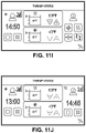
- FIGS. 11A-11O illustrate various screens displayed by the touch screen interface.
- the system can circulate cold or warm fluid, such as water, through a hose, into a therapy wrap, and then back to the fluid reservoirs of the system.
- the system can utilize a vapor compression system or other chiller technology to cool the cold water reservoir, and immersion heaters can be used to heat the hot water reservoir.
- the system can have two or more ports, in order to serve two or more patients simultaneously. Two or more air pumps can be utilized (one for each port) in order to provide pneumatic compression along with the thermal therapy.
- the system may have a single port and single air pump to treat just a single patient.
- the system 1000 can have a user interface 1002 on an upper front facing panel.
- the user interface 1002 can be a touch display.
- An on/off power button 1004 can be provided.
- the on/off power button can be located on, in or near the user interface 1002 .
- the upper front facing panel can also have a reservoir fill cover 1006 that can be opened to provide access to fill ports.
- Handles 1008 can also be provided to allow the user to move the system, which can have a based with 4 locking casters 1010 .
- a removable or openable front cover 1012 can provide access to the internal components of the system.
- Air vents 1014 , a hose holster 1016 , and a connector hose 1018 can be located on one or both the sides of the system.
- the rear of the system can have a fan 1020 , additional air vents 1022 , drain ports 1024 , a USB port 1026 and/or network port, an additional on/off power switch 1028 , a power cord inlet 1030 , and equipotential ground pins 1032 .
- COOLING water can be supplied and returned to the cold reservoir as controlled by the flow control valves associated with the port. Since there is only one cold reservoir in some embodiments, the cold reservoir temperature control may be common to both ports, or all ports for embodiments with more than 2 ports, and the temperature may be adjustable from the user interface, such as the home screen which can be the default display screen. Each port can have individual settings for treatment parameters, including treatment temperatures and duration and air pressure, which allow the system to deliver customized treatment to each wrap connected to the system.
- HEATING water can be supplied and returned to the hot reservoir as controlled by the flow control valves associated with the port. Since there may be only one hot reservoir in some embodiments, the hot reservoir temperature control may be common to both ports, or all ports for embodiments with more than 2 ports, and its temperature may be adjustable from the user interface, such as the home screen which can be the default display screen. Each port can have individual settings for treatment parameters, including treatment temperatures and duration and air pressure, which allow the system to deliver customized treatment to each wrap connected to the system.
- water supplied to the wraps can alternate between the hot and cold reservoirs based on the separate and customizable hot duration and temperature and cold duration and temperature settings.
- a typical treatment is alternating 3 min hot and 1 min cold.
- Air pressure can also be adjustable separately for the hot and cold treatments. For example the pressure could be set to high (i.e., 75 mmHg) during cold and med low (i.e., 25 mmHg) during hot.
- the pressure applied during cold treatment can be higher during cold treatment than hot treatment to work alongside with vasoconstriction during cold treatment.
- treatment duration selections may be limited to whole cycle values to end in a certain mode.
- a hot and cold cycle may be limited to minute increments, and a combined hot and cold cycle duration may be limited to a set value or upper limit.
- the single combined hot cold cycle may not exceed 4 minutes in some embodiments, meaning if the hot treatment is 3 minutes, then the cold treatment is 1 minute.
- a hot cold cycle may be limited to 2 to 10 minutes, or 4 to 20 minutes, or 2 to 30 minutes.
- the total treatment is configured to end with cold treatment or hot treatment by configuring the treatment times and number of cycles.
- FIG. 2 illustrates an embodiment of a user interface 2000 that can serve as a control panel.
- the user interface 2000 can be a touch screen with graphical icons that represent the different treatment modalities and can include adjustable parameter settings, such as hot and cold temperature settings for example.
- the control panel can use a 7′′ touchscreen TFT set in a traditional domed membrane switch. Most of the controls can be on the TFT display. A few buttons like power, STOP, home, etc. can be on the membrane switch. In some embodiments, a capacitive touch screen can be used.
- the pressure of gas furnished by the control unit is between about 0.25 psig and about 20 psig, preferably between about 0.25 psig and about 5 psig, and more preferably about 0.25 to about 1.5 psig.
- the control unit maintains a compressive force of between about 0.25 psig and about 5 psig.
- the control unit maintains a compressive force of between about 0.25 psig and about 0.5 psig.
- the pressure of gas furnished by the control unit is user selectable in increments of 5 mm Hg from 0 mm to about 75 mm.
- the pressure of gas furnished by the control unit is based on the patient's response. For example, if the patient is wearing the wrap during exercise, the pressure may vary based on how strenuous the exercise is. If the patient is having trouble breathing, the control unit may decrease the compressive force around the lungs.
- the pressure profile map may be set to adjust based on a predetermined routine. In various embodiments, the pressure profile map includes 3 minutes of slowly increasing pressure followed by 2 minutes of decreasing pressure. In various embodiments, the pressure profile map includes 30 seconds of increasing pressure followed by 15 seconds of decreasing pressure. In various embodiments, the pressure fluctuates at random. In various embodiments, the pressure profile map includes 2 minutes of compression followed by 1 minute with no compression.
- control unit delivers pulses of compression for massaging therapy.
- the wrap can be used with a rigid or semi-rigid support such as a brace.
- the control unit can apply and maintain a low pressure or no pressure when the control unit detects a brace in use with the wrap.
- the control unit can apply and maintain higher pressures when the control unit detects a brace not in use with the wrap.
- a low pressure is less than 10 psig, 5 psig, 4 psig, 3 psig, 2 psig, 1 psig, or 0.5 psig.
- a high pressure is greater than 0.5 psig, 1 psig, 2 psig, 3 psig, 4 psig, 5 psig, or 10 psig.
- FIG. 3 illustrates various pressure curve profiles: high (about 75 mmHg), medium high (about 50 mmHg), medium low (about 25 mmHg), and low (about 15 mmHg).
- the ramp time can be about 2 minutes to achieve the target pressure for high, medium high, and medium low, while the ramp time for low can be about 1 minute.
- the ramp times and target temperatures for the different settings can be adjustable, or can be predetermined and fixed.
- the default pressures for the cooling and heating modes is different. In other embodiments, the default pressures for the cooling and heating modes is the same.
- the therapy profile can specify the cold duration and temperature and compression, the hot duration and temperature and compression, and the duration of treatment or number of cycles to be run.
- the system allows named preset therapy sessions to be configured and saved by the user that can be later selected directly by name and/or a unique icon.
- FIGS. 4A and 4B illustrate an embodiment of a therapy wrap.
- the therapy wrap 20 is configured for wrapping to a portion of an animate body for delivering treatment.
- the body may include, but is not limited to, a mammalian body such as a human or an equine animal.
- the exemplary therapy wrap is in the form of a sleeve for connecting various components of heat transfer device 22 to the patient's body.
- the sleeve is similar in many respects to the sleeve disclosed by U.S. Pat. No. 7,896,910 to Schirrmacher et al. and cover disclosed by U.S. Pat. No. 6,695,872 to Elkins, the entire contents of which patents are incorporated herein for all purposes by reference.
- Exemplary therapy wrap 20 includes an opening 19 for directing heat transfer device 22 into a pouch or cavity in the sleeve interior. A portion of sleeve may be pulled back to reveal the pouch and facilitate positioning of the heat transfer device in the pouch as shown in FIG. 2B . Any suitable fastening means can be used to close the opening such as, but not limited to, a zipper.
- the pouches may be selectively positioned in predetermined locations on therapy wrap 20 .
- the pouches may be fixed into a position on the wrap based on parameters defined before use of the wrap. Such parameters may include user preferences or application demands.
- the sleeve is configured to position a bladder in one of a plurality of predefined locations.
- the predefined locations may be determined by user preferences.
- the predefined locations correspond to key areas for core cooling of the body.
- the sleeve may be shaped and configured for application to a mammal, and in various embodiments, a human. In various embodiments, the sleeve is shaped for applying to and covering all or part of a torso, a thoracic region, a cranial region, a throat region, a limb, and a combination of the same.
- Various aspects of the therapy wrap, in particular the sleeve, shape and design may be similar to the devices disclosed by U.S. Pat. No. 7,107,629 to Miros et al. and U.S. Patent Pub. No. 2005/0256556 A1 to Schirrmacher et al., the entire contents of which are incorporated herein for all purposes by reference.
- heat transfer device refers to the body heat exchanging component(s).
- the heat transfer device includes layers of material defining a flexible fluid bladder through which a liquid is circulated and a gas bladder in which a pressurized gas is injected.
- Exemplary heat transfer device 22 is in the form of a conventional multi-bladder assembly for positioning adjacent a treatment site of a body.
- the multi-bladder assembly is manufactured and configured using known techniques.
- a commonly used thermal bladder assembly uses both a compliant fluid bladder 25 for circulating heat transfer fluid and a gas pressure bladder 28 which overlays the fluid bladder (best seen in FIG. 2B ).
- the gas pressure bladder is adapted to inhibit edema and/or for pressing the fluid bladder against the body part to be subjected to heat exchange.
- outer gas pressure bladder 28 is adapted to receive a first fluid such as a gas (e.g., air) that can be regulated to provide the desired amount of inflation of the bladder or pressure therein. This inflation or pressure affects the compressive force applied to the animate body during use.
- Inner fluid bladder 25 is adapted to receive a fluid, such as a coolant which can be in the form of a cold liquid, to transfer heat away from the animate body part.
- the fluid supplied to the inner bladder can have a temperature higher than the animate body part to heat the body part.
- the hose and connector to attach the therapy wrap to the system can use a 3-port connector with a fluid inlet, a fluid outlet, and a gas port.
- the temperature of the hot reservoir can be adjustable from about 100 to 120 deg F, and the temperature of the cold reservoir can be adjustable from about 38 to 60 deg F.
- the temperature ranges can be determined by safety considerations (i.e., avoiding tissue damage) and freeze prevention of fluid in cold reservoir.
- the range limits can be adjusted by the user. For example the upper range for the hot reservoir can be lowered by the user to, for example, 110 or 115 F, and/or the lower range for the cold reservoir can be increased to 40 or 45 or 50 F.
- the user adjustable range is limited to adjustments made within a predetermined range so that the user cannot exceed a predetermined hot temperature limit or fall below a predetermined cold temperature limit.
- distilled water is provided and/or recommended for use to reduce scaling.
- descaling agents such as phosphoric acid, acetic acid, or citric acid can be flushed through the system. Instructions for descaling the system can be provided.
- addition of an antimicrobial and or scale inhibiter may also be recommended.
- the system is drained when not in use and drained/refilled periodically.
- the system 5000 can have easily accessible drain ports 5002 and fill ports 5004 .
- the fill ports 5004 can be located on the front facing portion of system near the user interface for increased access, which allows the user to easily add more fluid to the system if needed, even during treatment.
- a removable or openable cover 5006 can cover the fill ports 5004 .
- FIGS. 6-8B are schematic diagrams that illustrate various embodiments of the system.
- a hot gas bypass 6000 can be used and temperature can be controlled with an isolation valve 6002 upstream of the thermal expansion valve 6004 .
- ff a variable speed DC compressor 7000 is used the power may be lowered to allow use of a heater 7002 in the cold tank 7004 .
- FIG. 8A illustrates a schematic of the cold tank portion
- FIG. 8B illustrates a schematic of the hot tank portion.
- FIGS. 8A and 8B illustrate pumps 8001 , 8002 , 8003 , 8004 that can be used to pump fluid too the chiller 8005 , the heater 8006 , and between the cold tank 7004 and the hot tank 8007 .
- the pumps in combination with a system of valves can be used to control the fluid flow in the system.
- a small equalization tube 6500 may be a solution as shown in FIGS. 6 and 7 .
- This equalization tube 6500 would allow the tanks to equalize.
- the length and diameter of the tube could be sized to prevent fast equalization (which would dump hot water into the cold tank or vice versa).
- the length and diameter of the tube can be sized to allow up to about 1%, 5%, or 10% of the tank volume in fluid to pass through per minute.
- the equalization tube 6500 can be located on the upper portion of each tank, such as the upper 1/20, 1/10, 1 ⁇ 5, 1 ⁇ 4, or 1 ⁇ 3.
- a reversible pump between the reservoirs is another possible solution. This would have the advantage of being able to stop or start equalization at any time, and in any direction. Further advantage would be that hot water could be added to the cold tank, or vice versa, in order to more rapidly reach a desired tank temperature (i.e., when changing tank temperatures) or to prevent overshoot, etc.
- Another solution can be for overflow to be passed back and forth between the tanks at the filling ports shown in FIG. 5C .
- the filling ports can be housed in a receptacle that can accommodate fluid overflow from the reservoirs. As one reservoir overflows through its filling port, the receptacle is filled and the overflow fluid flows into the filling port of the other reservoir.
- tank fluid level management particularly the liquid leveling steps as described herein, can be generally performed outside of therapy, such as after therapy is completed.
- a liquid leveling procedure can be used even during therapy to return the tank levels to non-critical levels. This liquid leveling procedure can be implemented, for example, through control of the pumps described herein in connection with FIGS. 8A and 8B , for example.
- each reservoir can have its own fill port, as shown in FIG. 5B . Directing the water into both the hot tank and cold tank equally may be a challenge. If the fill line is above the level of each reservoir, then both reservoirs would equalize at that point. However, that does not leave room for additional head height in either tank during use, and the two tanks would mix freely, thus making temperature control of each tank more difficult and inefficient.
- an indicator on the user interface can indicate the fill level of the reservoirs and/or can indicate when a reservoir is fully filled.
- the tanks can have a fluid level sensor to determine the amount of fluid in the tank.
- FIGS. 9A and 9B an embodiment of a reservoir that addresses these concerns is shown in FIGS. 9A and 9B .
- the system comprises a Cold Reservoir 9001 , a Hot Reservoir 9002 and a Fill Port 9006 .
- Water may be poured into the Fill Port 9006 using a pitcher, hose, gallon jug, etc. Ease of filling may be aided by use of a wide, funnel or tapered shape to the fill port 9006 .
- the fill port 9006 may be sealed by a Fill Cap assembly 9004 .
- the fill cap assembly 9004 may include a Knob 9004 a a strainer 9004 b and a Tank Seal 9004 c .
- the Tank Seal may be configured to provide an opening between the reservoirs and the ambient environment in one position (open position), and to seal the opening between the reservoirs and the ambient environment in another position (closed position).
- open position there may be a conduit that connects the Hot and Cold Reservoirs. This allows for water to equalize between the hot and cold reservoirs once an adequate fill level is attained (between the Upper Fill Level 9019 and Lower Fill Level 9020 .
- the conduit between the Hot and Cold reservoirs may be closed off, in order to prevent exchange of fluid as fluid levels 9008 a - b and 9009 a - b change independently within the system. Vents in the Reservoirs 9005 , 9006 allow for the air pressure within the tanks to be nearly atmospheric.
- Cold Water Outlet 9010 and Hot Water Outlet 9011 may be located at the bottom surface of the reservoir, or may be at a level just above the reservoir bottom to prevent sediment from entering the fluidics lines.
- Cold Water Inlet 9012 and Hot Water Inlet 9013 would desirably be configured such to encourage mixing within the reservoir. Proper mixing, or forced convection around the Heater 9015 is particularly important to efficiently heat the water tank, and reduce surface temperature on the heater, which in turn reduces the likelihood of scaling developing on the Heater. For this reason, it may be desirable to include a Heater Baffle 9014 near the heater increase water velocity around the heater surface. The Baffle may be designed such to provide a torturous water path to further reduce the boundary layer at the surface of the heater. A similar approach may be used if a Heater is used in the Cold Reservoir as well.
- a sensor (preferably a Pressure Sensor) may be used in order to sense the water level in the tank.
- the Pressure Sensor 9018 , 9019 would be best placed near the bottom of the tank to most accurately measure Head Pressure within the tank. Reservoir Vents 9005 , 9006 would allow for accurate pressure measurement.
- Water level may be equalized or adjusted via a Tank Level Facilitator 9003 located adjacent to the reservoirs.
- the Tank Level Facilitator may passive, and could comprise of a simple orifice, or long length of tubing sized to provide a desired flowrate between the two reservoirs base simply on water level difference.
- the Tank Level Facilitator may also be an active device that pumps fluid from the Hot Reservoir to the Cold Reservoir or vice versa. This may be desirable if a significant water level imbalance is sensed, or to adjust the temperature in one of the tanks rapidly.
- alternative liquid level sensors or switches may be employed in order to provide a means of identifying whether the tank is above or below a certain point. This may be valuable as a redundant indicator, or to ensure that water was always above the heater element.
- An overflow prevention means may be to add an Overflow Conduit 9022 between the two Reservoirs. This may provide for a more rapid exchange of excess water to the opposite tank than could be done with a passive version of the Tank Level Facilitator.
- Overflow Drains 9023 , 9024 may be utilized in order to route excess water to outside the device, (in an overflow tank, or onto the ground). Additional sensors could be added to the Overflow Drains to sense this condition, or a means to detect moisture in the overflow tank could be added.
- FIG. 10A-10B Parameters for using the system are shown in FIG. 10A-10B .
- FIGS. 11A-11O Various screens displayed by the touch screen interface are shown in FIGS. 11A-11O .
- the system can include a controller and/or processor and memory for storing instructions and programming to implement the user interfaces described herein as well as controlling the system as described herein.
- the various components such as the pumps, the sensors, the compressors, the heat exchangers, the heaters, and the valves, can be controlled by the processor and/or send information to the processor.
- references to a structure or feature that is disposed “adjacent” another feature may have portions that overlap or underlie the adjacent feature.
- spatially relative terms such as “under”, “below”, “lower”, “over”, “upper” and the like, may be used herein for ease of description to describe one element or feature's relationship to another element(s) or feature(s) as illustrated in the figures. It will be understood that the spatially relative terms are intended to encompass different orientations of the device in use or operation in addition to the orientation depicted in the figures. For example, if a device in the figures is inverted, elements described as “under” or “beneath” other elements or features would then be oriented “over” the other elements or features. Thus, the exemplary term “under” can encompass both an orientation of over and under.
- the device may be otherwise oriented (rotated 90 degrees or at other orientations) and the spatially relative descriptors used herein interpreted accordingly.
- the terms “upwardly”, “downwardly”, “vertical”, “horizontal” and the like are used herein for the purpose of explanation only unless specifically indicated otherwise.
- first and second may be used herein to describe various features/elements (including steps), these features/elements should not be limited by these terms, unless the context indicates otherwise. These terms may be used to distinguish one feature/element from another feature/element. Thus, a first feature/element discussed below could be termed a second feature/element, and similarly, a second feature/element discussed below could be termed a first feature/element without departing from the teachings of the present invention.
- a numeric value may have a value that is +/ ⁇ 0.1% of the stated value (or range of values), +/ ⁇ 1% of the stated value (or range of values), +/ ⁇ 2% of the stated value (or range of values), +/ ⁇ 5% of the stated value (or range of values), +/ ⁇ 10% of the stated value (or range of values), etc.
- Any numerical values given herein should also be understood to include about or approximately that value, unless the context indicates otherwise. For example, if the value “10” is disclosed, then “about 10” is also disclosed. Any numerical range recited herein is intended to include all sub-ranges subsumed therein.
Landscapes
- Health & Medical Sciences (AREA)
- Engineering & Computer Science (AREA)
- Biomedical Technology (AREA)
- Heart & Thoracic Surgery (AREA)
- Vascular Medicine (AREA)
- Life Sciences & Earth Sciences (AREA)
- Animal Behavior & Ethology (AREA)
- General Health & Medical Sciences (AREA)
- Public Health (AREA)
- Veterinary Medicine (AREA)
- Thermotherapy And Cooling Therapy Devices (AREA)
- Pharmaceuticals Containing Other Organic And Inorganic Compounds (AREA)
Abstract
Description
| | 40 | | 1016 | | ||
| Length | ||||||
| 20 | inches | 500 | | |||
| Width | ||||||
| 17 | inches | 430 | | |||
| Water Volume | ||||||
| 3 | gallon (1-5 gallons) | 11 | liter | |||
| Weight | 150 | pounds | 45 | Kg | ||
Water Temperatures:
T=(Th−Tc)/2
T=Th−10 F (when switching from cold to hot)
T=Tc+10 F (when switching from hot to cold)
Time=60 seconds
Claims (18)
Priority Applications (1)
| Application Number | Priority Date | Filing Date | Title |
|---|---|---|---|
| US16/479,022 US11484438B2 (en) | 2017-01-19 | 2018-01-19 | Systems and methods for rapid contrast therapy |
Applications Claiming Priority (3)
| Application Number | Priority Date | Filing Date | Title |
|---|---|---|---|
| US201762448367P | 2017-01-19 | 2017-01-19 | |
| US16/479,022 US11484438B2 (en) | 2017-01-19 | 2018-01-19 | Systems and methods for rapid contrast therapy |
| PCT/US2018/014556 WO2018136814A1 (en) | 2017-01-19 | 2018-01-19 | Systems and methods for rapid contrast therapy |
Related Parent Applications (1)
| Application Number | Title | Priority Date | Filing Date |
|---|---|---|---|
| PCT/US2018/014556 A-371-Of-International WO2018136814A1 (en) | 2017-01-19 | 2018-01-19 | Systems and methods for rapid contrast therapy |
Related Child Applications (1)
| Application Number | Title | Priority Date | Filing Date |
|---|---|---|---|
| US17/975,026 Continuation US12193969B2 (en) | 2017-01-19 | 2022-10-27 | Systems and methods for rapid contrast therapy |
Publications (2)
| Publication Number | Publication Date |
|---|---|
| US20190328576A1 US20190328576A1 (en) | 2019-10-31 |
| US11484438B2 true US11484438B2 (en) | 2022-11-01 |
Family
ID=62909309
Family Applications (3)
| Application Number | Title | Priority Date | Filing Date |
|---|---|---|---|
| US16/479,022 Active 2039-07-09 US11484438B2 (en) | 2017-01-19 | 2018-01-19 | Systems and methods for rapid contrast therapy |
| US17/975,026 Active 2038-07-14 US12193969B2 (en) | 2017-01-19 | 2022-10-27 | Systems and methods for rapid contrast therapy |
| US19/018,901 Pending US20250143920A1 (en) | 2017-01-19 | 2025-01-13 | Systems and methods for rapid contrast therapy |
Family Applications After (2)
| Application Number | Title | Priority Date | Filing Date |
|---|---|---|---|
| US17/975,026 Active 2038-07-14 US12193969B2 (en) | 2017-01-19 | 2022-10-27 | Systems and methods for rapid contrast therapy |
| US19/018,901 Pending US20250143920A1 (en) | 2017-01-19 | 2025-01-13 | Systems and methods for rapid contrast therapy |
Country Status (6)
| Country | Link |
|---|---|
| US (3) | US11484438B2 (en) |
| EP (1) | EP3570795A4 (en) |
| CN (2) | CN110430847B (en) |
| AU (2) | AU2018210414B2 (en) |
| CA (1) | CA3050111A1 (en) |
| WO (1) | WO2018136814A1 (en) |
Families Citing this family (6)
| Publication number | Priority date | Publication date | Assignee | Title |
|---|---|---|---|---|
| CA3104850A1 (en) * | 2018-06-27 | 2020-01-02 | Coolsystems, Inc. | Thermal performance optimization in a thermal therapy device |
| NL2022837B1 (en) * | 2019-03-28 | 2020-10-02 | Kelvin Tms B V | SYSTEM AND DEVICE FOR COOLING AND / OR HEATING ALTHOUGH PART OF A BODY, AS WELL AS A METHOD FOR CONTROLLING SUCH SYSTEM |
| US11602482B2 (en) * | 2019-06-18 | 2023-03-14 | Diferynt Innovation, LLC | Water encapsulated and mechanical hybrid body massage chair with rapid heating and cooling control |
| US11454422B2 (en) * | 2020-03-27 | 2022-09-27 | Ademco Inc. | Water heating system for controlling an ability to set a parameter of a controller |
| US12029358B2 (en) | 2021-07-09 | 2024-07-09 | Kohler Co. | Bath with hot and cold water zones |
| WO2025226753A1 (en) * | 2024-04-25 | 2025-10-30 | Becton, Dickinson And Company | Improvements to targeted temperature managements systems including components and methods thereof |
Citations (17)
| Publication number | Priority date | Publication date | Assignee | Title |
|---|---|---|---|---|
| US5948012A (en) | 1996-05-09 | 1999-09-07 | Cincinnati Sub-Zero Products, Inc. | Cold therapy device |
| US6178562B1 (en) | 2000-01-28 | 2001-01-30 | Coolsystems, Inc | Cap and vest garment components of an animate body heat exchanger |
| WO2002026034A2 (en) | 2000-08-25 | 2002-04-04 | Organ Recovery Systems Inc. | Apparatus and method for maintaining and/or restoring viability of organs |
| US6695872B2 (en) | 2000-01-28 | 2004-02-24 | Coolsystems, Inc. | Therapy component of an animate body heat exchanger and method of manufacturing such component |
| US20040068309A1 (en) | 2002-10-08 | 2004-04-08 | Vital Wear, Inc. | Contrast therapy system and method |
| US20050256556A1 (en) | 2004-05-17 | 2005-11-17 | Coolsystems, Inc. | Modular apparatus for therapy of an animate body |
| US7107629B2 (en) | 2002-08-09 | 2006-09-19 | Coolsystems, Inc. | Apparel including a heat exchanger |
| US7198093B1 (en) | 1998-07-31 | 2007-04-03 | Coolsystems, Inc. | Compliant heat exchange panel |
| US7837638B2 (en) | 2007-02-13 | 2010-11-23 | Coolsystems, Inc. | Flexible joint wrap |
| WO2012028730A1 (en) | 2010-09-02 | 2012-03-08 | Thermather Sarl | Device for thermal treatment of the scalp |
| US20140142473A1 (en) | 2010-12-30 | 2014-05-22 | Mark H. Lowe | Reinforced therapeutic wrap and method |
| US20140222121A1 (en) | 2011-07-20 | 2014-08-07 | Scr Inc. | Athletic cooling and heating systems, devices and methods |
| NL2011288C2 (en) | 2013-08-09 | 2015-02-10 | A C S B V | Thermal system and method for controlling temperature. |
| US20150335468A1 (en) | 2012-06-22 | 2015-11-26 | Physiolab Technologies Limited | Thermal and/or pressure regulation control system |
| US20160022477A1 (en) | 2014-07-25 | 2016-01-28 | Cascade Wellness Technologies, Inc. | Thermal contrast therapy devices, methods and systems |
| CN105555347A (en) | 2012-03-24 | 2016-05-04 | 莱诺凯尔有限公司 | Systems and methods of preparing a controlled mixture for hyperthermal treatment |
| CN106313405A (en) | 2016-09-19 | 2017-01-11 | 中南大学 | Mold system with high/low-temperature rapid conversion function |
Family Cites Families (4)
| Publication number | Priority date | Publication date | Assignee | Title |
|---|---|---|---|---|
| US6660027B2 (en) * | 2001-10-11 | 2003-12-09 | Medivance Incorporated | Patient temperature control system with fluid preconditioning |
| TW201225944A (en) * | 2010-12-28 | 2012-07-01 | Univ Tatung | Cold/hot therapy device with temperature control |
| US9844460B2 (en) * | 2013-03-14 | 2017-12-19 | Zeltiq Aesthetics, Inc. | Treatment systems with fluid mixing systems and fluid-cooled applicators and methods of using the same |
| NL2011268C2 (en) * | 2013-08-05 | 2015-02-09 | Cornelis Petrus Gerardus Maria Boot | INSTALLATION FOR Dredging or deepening. |
-
2018
- 2018-01-19 CN CN201880019271.8A patent/CN110430847B/en active Active
- 2018-01-19 AU AU2018210414A patent/AU2018210414B2/en active Active
- 2018-01-19 US US16/479,022 patent/US11484438B2/en active Active
- 2018-01-19 WO PCT/US2018/014556 patent/WO2018136814A1/en not_active Ceased
- 2018-01-19 CN CN202210931263.9A patent/CN115381620A/en active Pending
- 2018-01-19 EP EP18742385.0A patent/EP3570795A4/en active Pending
- 2018-01-19 CA CA3050111A patent/CA3050111A1/en active Pending
-
2022
- 2022-10-27 US US17/975,026 patent/US12193969B2/en active Active
-
2023
- 2023-08-29 AU AU2023222842A patent/AU2023222842B2/en active Active
-
2025
- 2025-01-13 US US19/018,901 patent/US20250143920A1/en active Pending
Patent Citations (19)
| Publication number | Priority date | Publication date | Assignee | Title |
|---|---|---|---|---|
| US5948012A (en) | 1996-05-09 | 1999-09-07 | Cincinnati Sub-Zero Products, Inc. | Cold therapy device |
| US7198093B1 (en) | 1998-07-31 | 2007-04-03 | Coolsystems, Inc. | Compliant heat exchange panel |
| US6178562B1 (en) | 2000-01-28 | 2001-01-30 | Coolsystems, Inc | Cap and vest garment components of an animate body heat exchanger |
| US6695872B2 (en) | 2000-01-28 | 2004-02-24 | Coolsystems, Inc. | Therapy component of an animate body heat exchanger and method of manufacturing such component |
| WO2002026034A2 (en) | 2000-08-25 | 2002-04-04 | Organ Recovery Systems Inc. | Apparatus and method for maintaining and/or restoring viability of organs |
| US7107629B2 (en) | 2002-08-09 | 2006-09-19 | Coolsystems, Inc. | Apparel including a heat exchanger |
| US20040068309A1 (en) | 2002-10-08 | 2004-04-08 | Vital Wear, Inc. | Contrast therapy system and method |
| US7896910B2 (en) | 2004-05-17 | 2011-03-01 | Coolsystems, Inc. | Modular apparatus for therapy of an animate body |
| US20050256556A1 (en) | 2004-05-17 | 2005-11-17 | Coolsystems, Inc. | Modular apparatus for therapy of an animate body |
| US7837638B2 (en) | 2007-02-13 | 2010-11-23 | Coolsystems, Inc. | Flexible joint wrap |
| WO2012028730A1 (en) | 2010-09-02 | 2012-03-08 | Thermather Sarl | Device for thermal treatment of the scalp |
| US20140142473A1 (en) | 2010-12-30 | 2014-05-22 | Mark H. Lowe | Reinforced therapeutic wrap and method |
| US20140222121A1 (en) | 2011-07-20 | 2014-08-07 | Scr Inc. | Athletic cooling and heating systems, devices and methods |
| CN105555347A (en) | 2012-03-24 | 2016-05-04 | 莱诺凯尔有限公司 | Systems and methods of preparing a controlled mixture for hyperthermal treatment |
| US20150335468A1 (en) | 2012-06-22 | 2015-11-26 | Physiolab Technologies Limited | Thermal and/or pressure regulation control system |
| NL2011288C2 (en) | 2013-08-09 | 2015-02-10 | A C S B V | Thermal system and method for controlling temperature. |
| US20160022477A1 (en) | 2014-07-25 | 2016-01-28 | Cascade Wellness Technologies, Inc. | Thermal contrast therapy devices, methods and systems |
| US20160242957A1 (en) * | 2014-07-25 | 2016-08-25 | Cascade Wellness Technologies, Inc. | Thermal contrast therapy devices, methods, and systems |
| CN106313405A (en) | 2016-09-19 | 2017-01-11 | 中南大学 | Mold system with high/low-temperature rapid conversion function |
Non-Patent Citations (2)
| Title |
|---|
| Extended EP Search Report dated Sep. 23, 2020, from related EP application No. 18742385, 7 pages. |
| International Search Report and Written Opinion dated Mar. 29, 2018, from International Application No. PCT/US2018/014556, 7 pages. |
Also Published As
| Publication number | Publication date |
|---|---|
| CA3050111A1 (en) | 2018-07-26 |
| CN115381620A (en) | 2022-11-25 |
| EP3570795A1 (en) | 2019-11-27 |
| US20190328576A1 (en) | 2019-10-31 |
| AU2023222842B2 (en) | 2024-12-05 |
| EP3570795A4 (en) | 2020-11-04 |
| US20230096693A1 (en) | 2023-03-30 |
| US20250143920A1 (en) | 2025-05-08 |
| CN110430847B (en) | 2022-08-23 |
| US12193969B2 (en) | 2025-01-14 |
| CN110430847A (en) | 2019-11-08 |
| AU2018210414B2 (en) | 2023-06-01 |
| WO2018136814A1 (en) | 2018-07-26 |
| AU2023222842A1 (en) | 2023-09-21 |
| AU2018210414A1 (en) | 2019-08-01 |
Similar Documents
| Publication | Publication Date | Title |
|---|---|---|
| US20230277370A1 (en) | Thermal performance optimization in a thermal therapy device | |
| US12193969B2 (en) | Systems and methods for rapid contrast therapy | |
| US20240399046A1 (en) | Thermal control system | |
| EP2729097B1 (en) | Headwear for removing heat from a person's scalp in order to prevent hair loss | |
| EP2603183B1 (en) | A body part temperature regulating apparatus | |
| JP2004501702A (en) | Patient automatic controller | |
| KR20170092540A (en) | Device and method for reducing the body core temperature of a patient for hypothermia treatment by cooling at least two body parts of the patient | |
| ES2763568T3 (en) | Method for controlling a pressurized mattress system for a support structure | |
| US11771586B2 (en) | Thermal contrast therapy device | |
| CN106456876A (en) | Apparatus, system and method for controlling a temperature of a patient | |
| CN106456362A (en) | Apparatus, system and method for controlling the body temperature of a patient | |
| CN105943239A (en) | A temperature-adjustable multifunctional ice pillow |
Legal Events
| Date | Code | Title | Description |
|---|---|---|---|
| FEPP | Fee payment procedure |
Free format text: ENTITY STATUS SET TO UNDISCOUNTED (ORIGINAL EVENT CODE: BIG.); ENTITY STATUS OF PATENT OWNER: LARGE ENTITY |
|
| AS | Assignment |
Owner name: COOLSYSTEMS, INC., CALIFORNIA Free format text: ASSIGNMENT OF ASSIGNORS INTEREST;ASSIGNORS:LOWE, MARK H.;HUFF, BRYAN D.;MOORE, JOHN;SIGNING DATES FROM 20201021 TO 20201104;REEL/FRAME:054287/0967 |
|
| STPP | Information on status: patent application and granting procedure in general |
Free format text: NON FINAL ACTION MAILED |
|
| STPP | Information on status: patent application and granting procedure in general |
Free format text: RESPONSE TO NON-FINAL OFFICE ACTION ENTERED AND FORWARDED TO EXAMINER |
|
| AS | Assignment |
Owner name: AVENT, INC, GEORGIA Free format text: ASSIGNMENT OF ASSIGNORS INTEREST;ASSIGNOR:COOLSYSTEMS, INC.;REEL/FRAME:060165/0671 Effective date: 20220609 Owner name: AVENT, INC, GEORGIA Free format text: ASSIGNMENT OF ASSIGNOR'S INTEREST;ASSIGNOR:COOLSYSTEMS, INC.;REEL/FRAME:060165/0671 Effective date: 20220609 |
|
| STPP | Information on status: patent application and granting procedure in general |
Free format text: NOTICE OF ALLOWANCE MAILED -- APPLICATION RECEIVED IN OFFICE OF PUBLICATIONS |
|
| AS | Assignment |
Owner name: JPMORGAN CHASE BANK, N.A., AS ADMINISTRATIVE AGENT, ILLINOIS Free format text: SECURITY INTEREST;ASSIGNOR:AVENT, INC.;REEL/FRAME:060441/0445 Effective date: 20220624 |
|
| STPP | Information on status: patent application and granting procedure in general |
Free format text: PUBLICATIONS -- ISSUE FEE PAYMENT VERIFIED |
|
| STCF | Information on status: patent grant |
Free format text: PATENTED CASE |