US11477888B2 - Printed multifunctional skin for aerodynamic structures and associated systems and methods - Google Patents
Printed multifunctional skin for aerodynamic structures and associated systems and methods Download PDFInfo
- Publication number
- US11477888B2 US11477888B2 US16/154,509 US201816154509A US11477888B2 US 11477888 B2 US11477888 B2 US 11477888B2 US 201816154509 A US201816154509 A US 201816154509A US 11477888 B2 US11477888 B2 US 11477888B2
- Authority
- US
- United States
- Prior art keywords
- aerodynamic structure
- printed
- sensors
- aircraft
- sensor
- Prior art date
- Legal status (The legal status is an assumption and is not a legal conclusion. Google has not performed a legal analysis and makes no representation as to the accuracy of the status listed.)
- Active, expires
Links
Images


Classifications
-
- H—ELECTRICITY
- H05—ELECTRIC TECHNIQUES NOT OTHERWISE PROVIDED FOR
- H05K—PRINTED CIRCUITS; CASINGS OR CONSTRUCTIONAL DETAILS OF ELECTRIC APPARATUS; MANUFACTURE OF ASSEMBLAGES OF ELECTRICAL COMPONENTS
- H05K1/00—Printed circuits
- H05K1/16—Printed circuits incorporating printed electric components, e.g. printed resistors, capacitors or inductors
-
- B—PERFORMING OPERATIONS; TRANSPORTING
- B64—AIRCRAFT; AVIATION; COSMONAUTICS
- B64C—AEROPLANES; HELICOPTERS
- B64C1/00—Fuselages; Constructional features common to fuselages, wings, stabilising surfaces or the like
- B64C1/06—Frames; Stringers; Longerons ; Fuselage sections
- B64C1/12—Construction or attachment of skin panels
-
- B—PERFORMING OPERATIONS; TRANSPORTING
- B64—AIRCRAFT; AVIATION; COSMONAUTICS
- B64C—AEROPLANES; HELICOPTERS
- B64C3/00—Wings
- B64C3/26—Construction, shape, or attachment of separate skins, e.g. panels
-
- B—PERFORMING OPERATIONS; TRANSPORTING
- B64—AIRCRAFT; AVIATION; COSMONAUTICS
- B64C—AEROPLANES; HELICOPTERS
- B64C39/00—Aircraft not otherwise provided for
- B64C39/02—Aircraft not otherwise provided for characterised by special use
- B64C39/024—Aircraft not otherwise provided for characterised by special use of the remote controlled vehicle type, i.e. RPV
-
- B—PERFORMING OPERATIONS; TRANSPORTING
- B64—AIRCRAFT; AVIATION; COSMONAUTICS
- B64D—EQUIPMENT FOR FITTING IN OR TO AIRCRAFT; FLIGHT SUITS; PARACHUTES; ARRANGEMENT OR MOUNTING OF POWER PLANTS OR PROPULSION TRANSMISSIONS IN AIRCRAFT
- B64D45/00—Aircraft indicators or protectors not otherwise provided for
-
- B—PERFORMING OPERATIONS; TRANSPORTING
- B64—AIRCRAFT; AVIATION; COSMONAUTICS
- B64U—UNMANNED AERIAL VEHICLES [UAV]; EQUIPMENT THEREFOR
- B64U20/00—Constructional aspects of UAVs
- B64U20/80—Arrangement of on-board electronics, e.g. avionics systems or wiring
- B64U20/83—Electronic components structurally integrated with aircraft elements, e.g. circuit boards carrying loads
-
- B—PERFORMING OPERATIONS; TRANSPORTING
- B64—AIRCRAFT; AVIATION; COSMONAUTICS
- B64C—AEROPLANES; HELICOPTERS
- B64C1/00—Fuselages; Constructional features common to fuselages, wings, stabilising surfaces or the like
- B64C1/14—Windows; Doors; Hatch covers or access panels; Surrounding frame structures; Canopies; Windscreens accessories therefor, e.g. pressure sensors, water deflectors, hinges, seals, handles, latches, windscreen wipers
- B64C1/1476—Canopies; Windscreens or similar transparent elements
-
- B—PERFORMING OPERATIONS; TRANSPORTING
- B64—AIRCRAFT; AVIATION; COSMONAUTICS
- B64C—AEROPLANES; HELICOPTERS
- B64C27/00—Rotorcraft; Rotors peculiar thereto
- B64C27/006—Safety devices
-
- B—PERFORMING OPERATIONS; TRANSPORTING
- B64—AIRCRAFT; AVIATION; COSMONAUTICS
- B64C—AEROPLANES; HELICOPTERS
- B64C27/00—Rotorcraft; Rotors peculiar thereto
- B64C27/32—Rotors
- B64C27/46—Blades
- B64C27/473—Constructional features
-
- B—PERFORMING OPERATIONS; TRANSPORTING
- B64—AIRCRAFT; AVIATION; COSMONAUTICS
- B64D—EQUIPMENT FOR FITTING IN OR TO AIRCRAFT; FLIGHT SUITS; PARACHUTES; ARRANGEMENT OR MOUNTING OF POWER PLANTS OR PROPULSION TRANSMISSIONS IN AIRCRAFT
- B64D15/00—De-icing or preventing icing on exterior surfaces of aircraft
- B64D15/12—De-icing or preventing icing on exterior surfaces of aircraft by electric heating
-
- B—PERFORMING OPERATIONS; TRANSPORTING
- B64—AIRCRAFT; AVIATION; COSMONAUTICS
- B64D—EQUIPMENT FOR FITTING IN OR TO AIRCRAFT; FLIGHT SUITS; PARACHUTES; ARRANGEMENT OR MOUNTING OF POWER PLANTS OR PROPULSION TRANSMISSIONS IN AIRCRAFT
- B64D15/00—De-icing or preventing icing on exterior surfaces of aircraft
- B64D15/20—Means for detecting icing or initiating de-icing
-
- B—PERFORMING OPERATIONS; TRANSPORTING
- B64—AIRCRAFT; AVIATION; COSMONAUTICS
- B64D—EQUIPMENT FOR FITTING IN OR TO AIRCRAFT; FLIGHT SUITS; PARACHUTES; ARRANGEMENT OR MOUNTING OF POWER PLANTS OR PROPULSION TRANSMISSIONS IN AIRCRAFT
- B64D45/00—Aircraft indicators or protectors not otherwise provided for
- B64D2045/0085—Devices for aircraft health monitoring, e.g. monitoring flutter or vibration
-
- H—ELECTRICITY
- H05—ELECTRIC TECHNIQUES NOT OTHERWISE PROVIDED FOR
- H05K—PRINTED CIRCUITS; CASINGS OR CONSTRUCTIONAL DETAILS OF ELECTRIC APPARATUS; MANUFACTURE OF ASSEMBLAGES OF ELECTRICAL COMPONENTS
- H05K2201/00—Indexing scheme relating to printed circuits covered by H05K1/00
- H05K2201/10—Details of components or other objects attached to or integrated in a printed circuit board
- H05K2201/10007—Types of components
- H05K2201/10151—Sensor
-
- Y—GENERAL TAGGING OF NEW TECHNOLOGICAL DEVELOPMENTS; GENERAL TAGGING OF CROSS-SECTIONAL TECHNOLOGIES SPANNING OVER SEVERAL SECTIONS OF THE IPC; TECHNICAL SUBJECTS COVERED BY FORMER USPC CROSS-REFERENCE ART COLLECTIONS [XRACs] AND DIGESTS
- Y10—TECHNICAL SUBJECTS COVERED BY FORMER USPC
- Y10S—TECHNICAL SUBJECTS COVERED BY FORMER USPC CROSS-REFERENCE ART COLLECTIONS [XRACs] AND DIGESTS
- Y10S439/00—Electrical connectors
- Y10S439/91—Observation aide, e.g. transparent material, window in housing
Definitions
- the present invention relates generally to sensors and actuators attached to the structures, including aircraft.
- the aircrafts are typically equipped with instruments that can measure outside temperature, speed of the aircraft, outside/inside pressure, humidity, weight of the aircraft, etc.
- Some measurement sensors e.g., inside humidity and temperature
- other measurement sensors typically protrude outside of the aircraft (e.g., pitot tube for the pressure/speed measurements).
- the aircrafts also carry actuators (e.g., for landing gear deployment and retraction, for wing flaps, ice protection systems, etc.). These actuators are generally bulky and, when not exercised, are typically concealed within the aircraft.
- Some other sensing/actuation aerospace systems perform monitoring for the structures, ice protection, thermal management, vibration damping, etc.
- additional instruments/sensors may measure, for example, loading of the aircraft structure, especially during the development of the aircraft (Testing and Evaluation or T&E).
- strain sensors may be mounted on the load bearing parts of the aircraft structure during the testing of the aircraft, but the production aircraft would not include these strain sensors.
- Existing methods for assessment/management of the structural health, certification of flight readiness and fleet management are largely based on statistical data about the history of the aircraft, and depend heavily on the expertise of mechanics and engineers. Accordingly, there remains a need for the sensors and actuators that are compact, light, and inexpensive, and that can be used for the manned and unmanned aircraft.
- FIG. 1 is a schematic view of an aircraft equipped with sensors in accordance with an embodiment of the presently disclosed technology.
- FIG. 2 is an isometric view of an aircraft structure equipped with sensors and actuators in accordance with an embodiment of the presently disclosed technology.
- FIG. 3 is a top plan view of a printed multifunctional skin (pSKIN) equipped with sensors and actuators in accordance with an embodiment of the presently disclosed technology.
- pSKIN printed multifunctional skin
- FIGS. 4A-4C are isometric views of a pSKIN mounted on an aircraft structure in accordance with an embodiment of the presently disclosed technology.
- FIG. 5 is an exploded view of a pSKIN assembly in accordance with an embodiment of the presently disclosed technology.
- FIGS. 6A and 6B are plan and isometric views of an aircraft with sensors and actuators in accordance with an embodiment of the presently disclosed technology.
- FIGS. 7A-7F are schematic views of equipping an aircraft structure with sensors and actuators in accordance with an embodiment of the presently disclosed technology.
- FIG. 8 is an isometric view of printing sensors and actuators over an aircraft in accordance with an embodiment of the presently disclosed technology.
- FIG. 9 is an isometric view of a wind tunnel testing of sensors and actuators in accordance with an embodiment of the presently disclosed technology.
- FIGS. 10A and 10B are graphs of load measurements in accordance with an embodiment of the presently disclosed technology.
- FIGS. 11A-11C are cross-sectional views of aerodynamic structures in accordance with an embodiment of the presently disclosed technology.
- FIGS. 12A-12C are cross-sectional views of the aerodynamic structures in accordance with an embodiment of the presently disclosed technology.
- FIG. 13 is an isometric view of the aerodynamic structures in accordance with an embodiment of the presently disclosed technology.
- FIG. 14 is an isometric view of a panel in accordance with an embodiment of the presently disclosed technology.
- FIGS. 14A and 14B plan front and plan back views of the aerodynamic structure shown in FIG. 14 .
- FIG. 15 is an exploded view of a panel and a wind tunnel in accordance with an embodiment of the presently disclosed technology.
- FIG. 16 is an isometric view of an aircraft having a canopy in accordance with an embodiment of the presently disclosed technology.
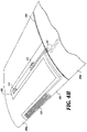
- FIG. 17 is an isometric view of a canopy in accordance with an embodiment of the presently disclosed technology.
- FIG. 17A is a cross-sectional view of the canopy shown in FIG. 17 .
- the system and methods can be used for equipping the aircraft or an aerodynamic structure with the sensors, actuators, and the supporting electronics (also referred to as printed multifunctional skin (pSKIN) or instrumentation), and for using the instrumentation for developing, testing and using the aircraft or the aerodynamic structure.
- pSKIN printed multifunctional skin
- the sensors may be built using 3D printing (also referred to as 3D manufacturing, additive printing, additive manufacturing, or direct write).
- the sensors and actuators may be printed directly over the aircraft structures or inside relatively shallow cavities of the aircraft structures.
- the host aircraft structures can also be made by 3D printing.
- the electronics may also be printed using specialized 3D printing equipment, methods and materials or “inks” (e.g., conductors, semiconductors, and dielectrics).
- 3D-printed electronic elements or components are interconnects, electrodes, resistors, capacitors, and active electronics.
- a relatively high density of sensors/actuators at a reduced unit cost/weight is advantageous over the bulky legacy systems.
- many sensors/actuators and their supporting electronics e.g., microcontrollers, op-amps, analog to digital (A/D) converters, resistors, power supplies, etc.
- A/D analog to digital
- resistors resistors
- power supplies etc.
- one or more relatively shallow openings e.g., 2-10 millimeter deep
- one or more relatively shallow openings e.g., 2-10 millimeter deep
- one or more relatively shallow openings may house power supplies, electronics, connectors, etc., for the sensors/actuators.
- the sensors/actuators closely approximate the surface of the aircraft structure, therefore not impeding or disturbing the airflow around the aircraft structure.
- the sensors/actuators may be 3D-printed directly over the outer surface of the aircraft structure in conjunction with manufacturing of the aircraft structure itself, or after the aircraft structure has been already manufactured.
- the sensors/actuators, and the electronics may be printable onto a conforming foil (e.g., a decal, also referred to as pSKIN) that is subsequently transferred to an existing aircraft structure.
- a conforming foil e.g., a decal, also referred to as pSKIN
- the conforming foils may have thickness of several micrometers (e.g., less than 100 ⁇ m, or 5 ⁇ m-100 ⁇ m) to several millimeters (e.g., 2-10 mm).
- Data from the 3D-printed sensors may provide an assessment of the state of the aircraft and/or an improved modeling (e.g., numerical simulation) of performance over time, therefore resulting in improved monitoring of the structure and better prediction of maintenance needs.
- the inventive technology can enable a “Digital Twin,” which is a mirror computer model of the aircraft that integrates numerical simulation with data from aircraft sensors (e.g., 3D-printed sensors), the aircraft maintenance history, and historical statistical data across aircraft of the same type to enable improved safety and reliability.
- the Digital Twin may be used to improve the models of the aircraft.
- a vane of an air fan may be equipped with 3D-manufactured sensors/actuators (a pSKIN) at an outer surface of the vane for monitoring or optimization of the air fan's performance.
- a pSKIN 3D-manufactured sensors/actuators
- the sensors, actuators, antennae, transducers, interconnects and other devices and elements of the pSKIN are exposed to the outside environment, while the electronics that supports these components of the pSKIN is disposed on the inner sides of the aircraft structure. As a result, the electronics may be better protected against the environmental effects (e.g., temperature extremes, moisture, pressure extremes, etc.).
- the traces connecting the printed devices or printed elements (sensors, actuators, transducers, pads, antennae, capacitors, resistors, inductors, batteries, logic circuits, memory, etc.) with the supporting electronics are partially run through the vias in the aerodynamic structure.
- the traces are routed around the edges of the aerodynamic structures (e.g., aircraft panels, canopies, windows, etc.) that carry the pSKIN. The edges may be rounded to reduce strain on the traces and improve their reliability.
- FIG. 1 is a schematic view of an aircraft 1000 equipped with sensors in accordance with an embodiment of the presently disclosed technology.
- the aircraft 1000 can carry 3D-printed pressure sensors 105 , temperature sensors 110 , and/or strain sensors 115 . These sensors may send their measurement data to a local or a central processing/display unit (e.g., a display in the airplane cockpit, computer carried by an unmanned vehicle, etc.). Other numbers and types of sensors are also possible.
- the aircraft 1000 may also carry 3D-printed actuators.
- FIG. 2 is an isometric view of an aircraft structure 200 equipped with sensors and actuators in accordance with an embodiment of the presently disclosed technology.
- the illustrated aircraft structure 200 may be, for example, a segment of an aircraft wing. In some embodiments, the aircraft structure 200 can include openings 255 for connecting with the adjacent aircraft structures.
- the aircraft structure 200 carries a decal (pSKIN) 280 .
- the combination of the pSKIN 280 and the aircraft structure 200 may be referred to as a smart structure or a smart device 2000 .
- the illustrated pSKIN 280 includes sensors 215 (e.g., strain sensors or strain gauges) and actuators 220 (e.g., heaters), but other sensors/actuators are also possible.
- the sensors 215 and actuators 220 are connected with conductive traces 230 to the connectors 225 (e.g., metal pads or plugs).
- the supporting electronics (not shown) may be connected through the connectors 225 to the sensors/actuators 215 / 220 .
- the supporting electronics may be at least partially embodied in the pSKIN 280 .
- the pSKIN 280 remains flexible because of its relatively small thickness (e.g., less than 10 ⁇ m to few mm). As a result, the pSKIN 280 may follow the shape of the aircraft structure 200 , and may be folded over the edges of the aircraft structure 200 .
- the pSKIN 280 can also be directly printed over the aircraft structure 200 .
- FIG. 3 is a top plan view of a pSKIN 380 with sensors and actuators in accordance with an embodiment of the presently disclosed technology.
- the pSKIN 380 includes sensors 215 (e.g., for temperature measurements), and an actuator 310 (e.g., a heater).
- the pSKIN 380 may include different type and number of sensors/actuators and supporting electronics, only sensors, or only actuators.
- the sensors 215 and the actuator 310 are connected with conductive traces (e.g., metal traces) with the connectors 225 .
- FIGS. 4A-4C are isometric views of the pSKIN 380 mounted on an aircraft structure in accordance with an embodiment of the presently disclosed technology.
- FIG. 4A shows the pSKIN 380 applied over the aircraft structure (e.g., an airfoil or a segment of the aircraft wing) 200 (collectively, a smart structure or a smart device).
- the illustrated pSKIN includes two sensors 215 and the actuator 310 , but other combinations of sensors/actuators are also possible.
- the pSKIN 380 may be folded over an edge 360 of the aircraft structure 200 .
- An integrated circuit (IC) chip 410 may be connected to the connectors 225 .
- IC integrated circuit
- the IC chip 410 may be bonded or soldered to the connectors 225 . In some embodiments, the IC chip 410 is on the side of the aircraft structure 200 . As a result, the IC chip 410 and the connectors 225 may be better protected against the environment, as explained with reference to FIGS. 4B-4C below.
- FIG. 4B shows an aircraft structure 200 a connected to another aircraft structure 200 b .
- the aircraft structures 200 a , 200 b may be segments of the aircraft wing or fuselage.
- the aircraft structures 200 a , 200 b may be segments of a rotorcraft, e.g., segments of a helicopter propeller. Since the illustrated aircraft structures 200 a , 200 b butt against each other, the IC chip 410 and the connectors 225 are protected against the environment, e.g., rain or air drag.
- conductive traces 230 or other wiring can electrically connect the pSKIN 380 with electronics (e.g., power supplies, controllers, etc.) away from the aircraft structure 200 a .
- the power supplies, controllers, etc. may reside on the aircraft itself, but away from the structure 200 a .
- the pSKIN 380 may be wirelessly connected (e.g., Bluetooth, WiFI, etc.) with external electronics.
- FIG. 4C shows aircraft structures 200 a , 200 b , 200 c that are mutually connected, and mounted on a stand 420 inside a wind tunnel 400 .
- the aircraft structure 200 a has its leading edge 350 oriented to face an incoming airflow at velocity U.
- the actuator 310 e.g., a heater
- the downstream sensors 215 e.g., thermocouples or strain gauges
- the pSKIN 380 may be used for, e.g., deicing or flow control.
- the IC chip 410 and/or the connectors 225 are less exposed to the environmental force and degradation since they are not in the path of the flow.
- the conductive traces 230 may connect the pSKIN 380 with electronics outside of the wind tunnel 400 .
- FIG. 5 is an exploded view of a pSKIN assembly 5800 in accordance with an embodiment of the presently disclosed technology.
- the pSKIN assembly 5800 includes a pSKIN 580 having a foil 580 a (e.g., a polymer, wax paper, thin PCB, etc.) with the 3D-printed electronics and a layer of adhesive 580 b (e.g., an epoxy).
- the illustrated pSKIN 580 is covered with a protective cover 510 having a protective foil 510 a (e.g., a polymer) and a layer of adhesive 510 b .
- the protective cover 510 and/or the pSKIN 580 can be made by casting one-part epoxy resins onto a wax paper or olefin based foils.
- the foils 580 a / 510 a may be rigid enough to handle, yet remain pliable enough to conform to many curved surfaces.
- the sensors/actuators e.g., a heater 310
- conductive traces 230 , and connectors 225 can be 3D-printed over the foil 580 a .
- the sensors, actuators and/or electronics of the pSKIN 580 may be made by lithography or screen printing. The combination of the pSKIN 580 and the protective cover 510 can be applied over the aircraft structure 200 .
- in-situ curing can be used to cure the pSKIN assembly 5800 without affecting the aircraft/host structure substrate using, for example, photonic based curing, UV based curing, electromagnetic systems such as induction heating and microwaves, and/or thermal blankets.
- the cured pSKIN assembly 5800 retains good adhesion and functionality in presence of a hole 290 (e.g., a rivet hole).
- FIGS. 6A and 6B are plan and isometric views of an aircraft 6000 that carries sensors and actuators in accordance with an embodiment of the presently disclosed technology.
- FIG. 6A is a plan view of the aircraft 6000 that includes several sensors, actuators and power supplies (e.g., batteries).
- the aircraft 6000 and the sensors/actuators/electronics may be referred to as a smart structure or a smart device 6100 .
- the aircraft 6000 may be, for example, an unmanned airplane, but other types of aircraft are also possible.
- FIG. 6A shows an embodiment of the aircraft 6000 that carries several sensors and actuators: thermocouples 610 , ice sensors 620 , sensors 215 (e.g., strain sensors), and pressure sensors 105 (collectively, pSKIN or printed multifunctional skin). Other numbers and arrangement of the sensors and actuators are also possible.
- the sensors/actuators may be at least in part powered by batteries 630 .
- the aircraft 6000 may include electronics (not shown) for digital or analog processing, wireless data transmission to ground or to another aircraft, etc.
- the aircraft 6000 may include heaters that are turned on and off based on the signal from the ice sensors 620 that is processed by the on-board electronics.
- high-bandwidth pressure sensors can be coupled with ionic wind generators for boundary layer control.
- distributed sensors can be used to determine the position of streamwise vortices, and then surface electrodes for ionic wind may nudge or force the vortices back to their optimal location using a closed-loop control system.
- more efficient aerodynamic vehicles with low skin friction can be developed to, for example, reduce fuel consumption.
- FIG. 6B shows the aircraft 6000 that has openings in the aircraft for housing the sensors, actuators and power supplies.
- openings 105 h may be shaped and configured to receive the pressure sensors 105
- openings 630 h may be shaped and configured to receive the batteries 630 . Manufacturing of the openings 105 h , 630 h is discussed with reference to FIGS. 7A-7F below.
- FIGS. 7A-7F are schematic views of equipping an aircraft structure with sensors and actuators in accordance with an embodiment of the presently disclosed technology.
- FIG. 7A schematically illustrates a step 7100 for manufacturing the aircraft structure 200 .
- a 3D printer 710 may eject a 3D material 720 (e.g., aerosols, powdered metals, melted materials, polymer ceramic composites, etc.) that form the aircraft structure 200 .
- the 3D printer 710 may be controlled by a controller or a computer (not shown).
- FIG. 7B schematically illustrates a step 7200 for manufacturing the aircraft structure 200 .
- an opening 730 e.g., a pocket or a housing
- the electronics for sensors/actuators are configured to control the opening 730 .
- FIG. 7C schematically illustrates a step 7300 for manufacturing the aircraft structure 200 .
- an electronics printer 740 also referred to as “3D electronics printer” or “additive electronics printer” or “direct write electronics printer”) prints electronics 750 a for supporting the sensors/actuators.
- the electronics printer 740 places a functional material 745 on the surface the electronics 750 a .
- Active and passive elements may be placed directly on the surface or inside the pockets of the aircraft structure 200 .
- the electronics printer 740 can directly deposit a range of commercial and custom electronic materials such as resistors, conductors (copper, silver, gold, etc.), dielectrics, piezoelectrics, carbon nanotubes, adhesives, polymers, and other materials.
- electronics 750 b may also be printed in-situ or may be pre-made using a 3D printer or conventional methods (e.g., surface mount technologies).
- FIG. 7D schematically illustrates a step 7400 for manufacturing the aircraft structure 200 .
- a buildup of the aircraft structure 200 continues using the 3D printer 710 .
- the electronics 750 a / 750 b may become encapsulated in the 3D material 720 , leaving openings 760 for accessing the electronics 750 a / 750 b.
- FIG. 7E schematically illustrates a step 7500 for manufacturing the aircraft structure 200 .
- a wiring 770 may be added by the electronics printer 740 .
- the 3D printer 710 may print conductive materials, e.g., the wiring 770 inside the openings 760 .
- the wiring 770 may connect the electronics 750 a / 750 b to the surface of the aircraft structure 200 .
- FIG. 7F schematically illustrates a step 7600 for manufacturing the aircraft structure 200 .
- the electronics printer 740 may add, for example, the pressure sensor 105 , the temperature sensor 110 and the strain sensor 115 to the surface of the aircraft structure 200 .
- different combinations of the sensors/actuators may be added by the electronics printer 740 , for example, the pSKIN 580 may combine thermistor-based temperature sensors, strain gauges, and pressure sensors.
- the sensors/actuators are relatively thin in comparison to the aircraft structure 200 .
- the sensors/actuators may be less than 10 ⁇ m, less than 100 ⁇ m, or less than 2 mm thick.
- the wiring 770 connect the electronics 750 a / 750 b with the sensors/actuators of the pSKIN 580 .
- FIG. 8 is an isometric view of printing sensors and actuators over the aircraft 6000 with in accordance with an embodiment of the presently disclosed technology.
- the electronics printer 740 may be positioned above the aircraft 6000 , and may be driven by a computer controlled positioning system (not shown).
- the electronics printer 740 may use different functional material for printing different components of the pSKIN (e.g., the functional material for the conductive traces 230 and dielectric-based ink for the insulation of the ice sensor 620 ).
- Some embodiments of the sensors that are manufacturable by the electronics printer 740 are temperature sensors, strain sensors, static or low frequency pressure sensors, force sensitive resistors, dynamic or high frequency pressure sensors, heat flux sensors, negative pressure or vacuum sensors, piezoelectric sensors, vibration sensors, impact sensors, airflow sensors, acoustic sensors, electric field sensors, antennas, magnetic field sensors, crack detection sensors, ice sensors, sensors detecting other characteristics relating to flight, sensors detecting other characteristics of the environment, sensors detecting other characteristics relating to aircraft structural health, and a metamaterial with an ordered one-dimensional, two-dimensional or three-dimensional structure.
- the actuators that are manufacturable by the electronics printer 740 are: ice remediation heaters, ion actuators, plasma actuators, piezoelectric transducers, aircraft controls, and other planar functional devices printed or adhered to the surface of the aerodynamic structure.
- the actuators are functional coatings that change the surface temperature, color (optical properties), texture/roughness, luminosity (lights/infrared signature), and/or other properties of the surface. These actuators may be deposited by 3D-printing.
- an OPTOMEC Aerosol Jet (AJ) system can be used as the electronics printer 740 .
- the pSKIN sensors/actuators may be printed directly on metallic structures, other 3D-printed structures, and other suitable substrates such as composites.
- Some examples of functional material 745 are: carbon nanotube inks, conductors (e.g., metals), insulators, semiconductors, semimetals, resistors, dielectrics, adhesives, epoxies, filled epoxies, polymers, filled polymers, elastomers, filled elastomers, ceramic particulates, piezoelectric materials, magnetic materials, functional materials, graphene inks, biological materials, and composites of these material.
- the strain sensor (strain gauge) 115 can be printed over different substrates (e.g., aircraft structure 200 ): glass, polyimide, composite materials, ceramics, and anodized aluminum 2024 T3.
- the functional materials 745 may include metals, elastomers, piezolectrics, PARU silver nano ink, Heraeus PEDOT:PSS 1000 and Brewer Science Carbon Nano Tube (CNT) inks.
- the electrical resistance for the functional material 745 is between 100 ⁇ and 350 ⁇ for Pam silver, around 200 k ⁇ for CNTs and between 0.4 M ⁇ and 0.6 M ⁇ for PEDOT:PSS.
- strain sensors can be printed in about 10 layers with a total print time of about 60 minutes at 4 mm/s translations.
- the temperature sensors 110 are thermocouples or thermistors. Conventional manufacturing of the thermocouples requires an oxygen free atmosphere and high curing temperatures. In some embodiments of the present technology, a low-temperature curing process for the thermocouples can be used by having the functional material that requires low processing temperature conditions.
- the thermistors can be made of semiconducting mixtures of oxides of transition metals with low processing temperature conditions (e.g., silicon based silistors, switching type materials, or graphite). In some embodiments, these materials may be solvable in a solvent to produce the functional material 745 .
- the functional material 745 may include Molybdenum Disulphide (MoS2) and Molybdenum Disulphide (MoS2) diluted 1:1 with Toluene (polar solvent), to lower viscosity and to facilitate printing.
- the functional material 745 may include Molybdenum Disulphide (MoS2), Magnetite, and poly (3,4-ethylenedioxythiophene) polystyrene sulfonate (PEDOT:PSS).
- MoS2 Molybdenum Disulphide
- Magnetite Magnetite
- PEDOT:PSS poly (3,4-ethylenedioxythiophene) polystyrene sulfonate
- the sensors may include printed pressure sensors 105 , for example, Force Sensitive Capacitors (FSCs), Force Sensitive Resistors (FSRs), and/or Lead Zirconate Titanate (PZT) sensors.
- FSCs Force Sensitive Capacitors
- FSRs Force Sensitive Resistors
- PZT Lead Zirconate Titanate
- the FSC can operate by continuously evaluating a capacitance of a printed capacitor having two parallel conductive plates separated by a dielectric material.
- the conductor plates and dielectric material can be made relatively thin, increasing the static capacitance of the sensor.
- the printed conductor plates/dielectric material may have the thickness of about 100 nm to 30 ⁇ m.
- PARU silver nano ink can be used as the conductive material, and Sigma Aldrich polyimide as the dielectric layer.
- the sensors may be manufactured by sintering micro-scale lead zirconate titanate (PZT) films with relatively low substrate temperature increases.
- the functional material 745 may include ink formulated from PZT nanoparticles, solvent, dispersant and adhesion promoter. In some embodiments, the inks may dry for a few hours (e.g., two hours) in a vacuum at about 200° C. In some embodiments, the functional material 745 may be photonically sintered using sub-millisecond pulses of broad spectrum light.
- the remanent polarization and coercive field for thermally sintered PZT film were 16.1 ⁇ C/cm2 and 4.3 kV/cm, respectively.
- the remanent polarization can be 27.7 ⁇ C/cm2 and coercive field can be 3.1 kV/cm.
- the piezoelectric voltage constants (g31) for the two film groups can be ⁇ 5.0 ⁇ 10 ⁇ 3 V-m/N (for thermally sintered functional material) and ⁇ 5.5 ⁇ 10 ⁇ 3 Vm/N (for photonically sintered functional material).
- the foregoing values indicate that the PZT films were successfully sintered.
- a colloidal based functional material 745 may be used.
- the curing and sintering of the PZT particles in the functional material 745 may occur in a temperature range of 150-200° C., therefore being suitable for direct printing over many metallic and non-metallic aircraft structures 200 .
- FIG. 9 is an isometric view of a wind tunnel testing of sensors and actuators in accordance with an embodiment of the presently disclosed technology.
- the aircraft 100 carries the sensor 310 (e.g., a heater) and the sensor 215 (collectively, pSKIN).
- the aircraft 100 is mounted on the stand 420 , and oriented to face the incoming airflow at velocity U.
- the sensors/actuators of the pSKIN may make measurements and/or manipulate the fluid flow to, for example, improve flight characteristics of the aircraft 100 .
- FIGS. 10A and 10B are graphs of load measurements in accordance with an embodiment of the presently disclosed technology.
- FIG. 10A is a graph of the load over time
- FIG. 10B is a graph of the measured load over time.
- the horizontal axes for both graphs are time in seconds.
- the vertical axis of the graph in FIG. 10A corresponds to applied load in lbF.
- the applied load increases over the time, reaches a peak of about 250 lbF after about 19 seconds, and then decreases to about 25 lbF after 25 seconds.
- the load may be applied over an aircraft structure (e.g., a wing of an aircraft).
- the vertical axis of the graph in FIG. 10B corresponds to the resistance in ⁇ of a strain sensor (e.g., the strain sensor 115 placed over an aircraft wing).
- the behavior of the measured resistance in ⁇ in FIG. 10B generally corresponds to the loading shown in FIG. 10A , i.e., the shape, maximum, and minimum of the graph in FIG. 10B generally follows the shape of graph in FIG. 10A , therefore indicating a generally linear response of the strain sensor.
- a linear response of a sensor is a preferred response.
- FIGS. 11A-11C are cross-sectional views of aerodynamic structures in accordance with an embodiment of the presently disclosed technology.
- a combination of the aerodynamic structures may be referred to as an aerodynamic apparatus or device (e.g., an airplane, a rotorcraft, an unmanned aerial vehicle, a fan, a turbine, a pump, a submarine, a boat, a car, a train, a motorbike, a helmet, a pair of glasses, goggles, a windshield, etc.).
- FIG. 11A shows aerodynamic structures (e.g., aircraft wing sections) 2000 - 1 and 2000 - 2 .
- FIG. 11B shows aerodynamic structure 2000 - 1 that carries pSKIN.
- one side of the aerodynamic structures 2000 - 1 includes the heater 310 and the strain gauge 215 , but other types and numbers of 3D-printed sensors, actuators, and devices are also possible.
- the printed conductive traces 230 electrically connect these 3D-printed elements (e.g., sensors, actuators, other devices) of the pSKIN with the electronic components 750 at a surface on the opposite side of the aerodynamic structures 2000 - 1 .
- the electronic components 750 which may be sensitive to heat, pressure, moisture, etc., can be better protected against environmental conditions.
- a cable 235 may electrically connect the sensors/actuators/devices to the electronic components 750 at the internal side of the aerodynamic structures.
- a rotorcraft blade 2000 - 1 may be electrically connected with a hub 2000 - 3 via the cable 235 .
- FIG. 11C shows the aerodynamic structure 2000 - 1 that carries some components of the pSKIN at its leading or trailing edge.
- the strain gauge 215 and/or the heater 310 may be disposed at the leading or trailing edge of the aerodynamic structure 2000 - 1 .
- additional or different locations for the components of the pSKIN are also possible.
- FIGS. 12A-12C are cross-sectional views of the aerodynamic structures in accordance with an embodiment of the presently disclosed technology.
- FIG. 12A shows spacing at the mechanical interfaces (connections) between the aerodynamic structures 2000 - 1 , 2000 - 2 and 2000 - 4 .
- an outer or external surface (ES) of the aerodynamic structures 2000 - 1 , 2000 - 2 and 2000 - 4 faces the outside environment (OE), while an inner or internal surface (IS) faces, for example, the inner environment (IE) of the interior of the plane.
- OE outside environment
- IS inner or internal surface
- IE inner environment
- the aerodynamic structures 2000 - 1 , 2000 - 2 and 2000 - 4 may be outside panels of an aircraft wing or fuselage, while the aerodynamic structure 2000 - 3 may be the interior of the aircraft wing or fuselage.
- the environmental conditions at the ES can be significantly different than those at the IS. For example, temperature extremes, moisture content oscillations, pressure extremes, etc. may be significantly higher at the ES than at the IS.
- FIG. 12B shows elements of the pSKIN at the ES of the aerodynamic structure 2000 - 1 .
- the traces 230 that connect the elements of the pSKIN at the ES of the aerodynamic structure with the electronic components 750 at the IS may partially run along the interfaces between the aerodynamic structures 2000 - 1 , 2000 - 2 , 2000 - 4 ).
- the aerodynamic structures may be curved or flat, and their edges may be curved (e.g., through a fillet at the edge) or may include relatively sharp edges.
- a fillet radius of the edge may be larger than 300 ⁇ m to reduce damage to the traces 230 during fabrication, assembly and/or operation.
- sharp edges tend to damage deposited inks, therefore potentially breaking the electrical continuity of the trace 230 .
- sharp edges of a structure can be covered with a non-conductive layer (e.g., polyimide, epoxy, or aluminum oxide) to provide a smooth edge for the printed interconnects.
- a non-conductive layer e.g., polyimide, epoxy, or aluminum oxide
- the same procedure may be used on thin structures (e.g., where the thickness is less than 3 mm).
- FIG. 12C shows the aerodynamic structure 2000 - 1 that has vias 1230 for routing the traces 230 through the structure.
- the vias 1230 are relatively small perforations (e.g., having a diameter in the range of 200 ⁇ m to 1000 ⁇ m) that extend between the ES and the IS of the aerodynamic structure.
- the traces 230 may be 3D-printable within the vias 1230 .
- pre-made interconnects e.g., pins
- the diameter and separation between vias 1230 may depend on the material thickness, electrical conductivity requirements, substrate electrical properties (i.e. conductive vs non-conductive), position on the aerodynamic structure, and pressurization requirements based, for example, on a difference of pressure between the ES and IS, and the strength of the material of the aerodynamic structure.
- FIG. 13 is an isometric view of an aerodynamic structure in accordance with an embodiment of the presently disclosed technology.
- FIG. 13 shows a cavity or bay in an aircraft structure 3000 (e.g., landing gear well, cargo bay, service panel, pod, etc.) that houses an aerodynamic structure or apparatus 2000 (e.g., a missile).
- the aircraft structure 3000 protects the aerodynamic structure 2000 during, for example, lab testing or operational flight (e.g., before the release of the missile 2000 ).
- the structure 3000 may be carried by an aircraft or may be configured in a wind tunnel section.
- one or more panels 2100 are instrumented with 3D-printed sensors and/or actuators (e.g., pressure sensors, thermal actuators, temperature sensors, strain gages, antennae, transducers etc.). These sensors/actuators/devices may be disposed on the external surface ES of the panel 2100 .
- the external surface ES is the one that faces the airflow conditions inside the cavity of structure 3000 , i.e., the external surface ES of the panel 2100 faces the missile 2000 .
- the internal surface IS faces the more benign conditions outside of the structure 3000 , therefore, for example, having the electronic components less exposed to the harsh environment within the structure 3000 .
- FIG. 14 is an isometric view of the panel 2100 in accordance with an embodiment of the presently disclosed technology.
- FIGS. 14A and 14B plan front and plan back views of the aerodynamic structure shown in FIG. 14 .
- the panel 2100 carries the sensors, antennae, and/or actuators at the external surface ES.
- Some examples of such sensors and actuators are 3D-printed strain gauges 215 , thermocouples 610 , and heaters 310 .
- Other sensors, devices, and/or actuators are possible in different embodiments.
- the ES faces the outside environment (which may be interior of the structure 3000 , as explained above), thus exposing the sensors and actuators to the outside environment.
- the internal surface IS faces the exterior of the aircraft structure 3000 , where, in general, the environment is less harsh and/or subject to smaller oscillations in pressure, temperature, force, precipitation, etc.
- the IS carries the electronic components or assemblies 750 (e.g., controllers, power supplies, processors, etc.).
- electrical interconnects may be 3D-printed along the ES, turned over an edge 2100 -EDG of the panel (e.g., through the double turn or fold), and routed further to the IS.
- the edge 2100 -EDG includes a fillet radius R that smooths the surface and removes the sharp edges, thus improving the integrity and reliability of the traces.
- the fillet radius of about 600 ⁇ m or larger provides a relatively smooth surface that promotes better wetting and attachment of printable inks or materials.
- the electrically conductive traces 230 are encapsulated with polymer coatings (e.g., polyimide, polyurethane, or epoxies) or ceramic coatings (e.g. aluminum oxides) 230 -C for electrical insulation from electrically conductive substrates (e.g. aluminum or carbon-based composites), environmental protection, and durability. These coatings may reduce fretting and other wear mechanisms during assembly and operation of the panel 2100 .
- polymer coatings e.g., polyimide, polyurethane, or epoxies
- ceramic coatings e.g. aluminum oxides
- FIG. 15 is an exploded view of the panel 2100 and the aircraft structure 3000 in accordance with an embodiment of the presently disclosed technology.
- the panel 2100 may be a pre-manufactured or 3D-printed polycarbonate window that uses a seal 2110 (e.g., a polyurethane seal) for sealing.
- the panels may be brittle substrates (e.g., ceramics), glass, composites, metals, or other materials where drilling may be risky or not allowed at all.
- the panel 2100 and the seal 2110 may be kept in place by opposing frames 2105 (e.g., aluminum or other metal frames).
- the sensors/actuators face the inner cavity of the structure 3000 , where the working conditions are replicated.
- the electronic components face away from the inner cavity of the structure 3000 , therefore being exposed to a less harsh environment.
- the panels e.g., a canopy, a window, a windshield, or lens
- the panels may be integrated with the aerodynamic structure or apparatus, as explained in conjunction with FIGS. 16-17A below.
- FIG. 16 is an isometric view of an aircraft 100 having a canopy 2200 in accordance with an embodiment of the presently disclosed technology.
- the canopy 2200 protects the pilot and sensitive electronics against the outside environment.
- the canopy may be made of glass, plastics (e.g. polycarbonate), or ceramics. As a result, drilling holes in the canopy 2200 may be difficult and/or not allowed.
- the sensors, actuators, antennae, and/or transducers may be 3D-printed on the outer surface ES of the canopy 2200 , and electrically connected with the electronic components 750 on the inner side IS of the canopy, as explained below in conjunction with FIGS. 17 and 17A .
- FIG. 17 is an isometric view of a canopy in accordance with an embodiment of the presently disclosed technology.
- FIG. 17A is a cross-sectional view of the canopy shown in FIG. 17 .
- the illustrated canopy 2200 carries the sensors and actuators on its external surface ES. These sensors and actuators may be electrically connected through the traces 230 with the electronic components 750 . In operation, the traces 230 provide an electrical path for the signal/power exchange between the ES and the IS. As a result, drilling through the canopy 2200 may be avoided.
- the edge of the canopy 2200 may be rounded as explained with respect to the panels 2100 .
- the inventive technology may be used to 3D-print the sensors, actuators, traces, and/or electronics on the aerodynamic structures such as wings, blades, propellers, engine components, prosthesis, aircraft, unmanned air vehicles, windshields, goggles, lenses, camera lenses, and glasses.
Landscapes
- Engineering & Computer Science (AREA)
- Aviation & Aerospace Engineering (AREA)
- Mechanical Engineering (AREA)
- Microelectronics & Electronic Packaging (AREA)
- Remote Sensing (AREA)
- Details Of Aerials (AREA)
Abstract
Description
Claims (21)
Priority Applications (1)
| Application Number | Priority Date | Filing Date | Title |
|---|---|---|---|
| US16/154,509 US11477888B2 (en) | 2018-10-08 | 2018-10-08 | Printed multifunctional skin for aerodynamic structures and associated systems and methods |
Applications Claiming Priority (1)
| Application Number | Priority Date | Filing Date | Title |
|---|---|---|---|
| US16/154,509 US11477888B2 (en) | 2018-10-08 | 2018-10-08 | Printed multifunctional skin for aerodynamic structures and associated systems and methods |
Publications (2)
| Publication Number | Publication Date |
|---|---|
| US20200113054A1 US20200113054A1 (en) | 2020-04-09 |
| US11477888B2 true US11477888B2 (en) | 2022-10-18 |
Family
ID=70051878
Family Applications (1)
| Application Number | Title | Priority Date | Filing Date |
|---|---|---|---|
| US16/154,509 Active 2041-07-11 US11477888B2 (en) | 2018-10-08 | 2018-10-08 | Printed multifunctional skin for aerodynamic structures and associated systems and methods |
Country Status (1)
| Country | Link |
|---|---|
| US (1) | US11477888B2 (en) |
Cited By (1)
| Publication number | Priority date | Publication date | Assignee | Title |
|---|---|---|---|---|
| US12024300B2 (en) * | 2019-12-02 | 2024-07-02 | Lockheed Martin Corporation | Method and system for ice detection |
Families Citing this family (5)
| Publication number | Priority date | Publication date | Assignee | Title |
|---|---|---|---|---|
| US11613340B2 (en) * | 2020-05-21 | 2023-03-28 | North West Heli-Structures Incorporated | Panel systems and methods for helicopters |
| GB202104305D0 (en) * | 2021-03-26 | 2021-05-12 | Rolls Royce Plc | Computer-implemented methods for determining damage to an aircraft |
| CN113459199A (en) * | 2021-06-24 | 2021-10-01 | 成都飞机工业(集团)有限责任公司 | Hole making method for porous similar skin part |
| EP4138525A1 (en) * | 2021-08-17 | 2023-02-22 | Airbus S.A.S. | Method for producing a panel with integrated electronics |
| US12079010B2 (en) * | 2022-08-17 | 2024-09-03 | Beta Air, Llc | Apparatus for pre-flight preparation for electric aircraft |
Citations (23)
| Publication number | Priority date | Publication date | Assignee | Title |
|---|---|---|---|---|
| DE2402830A1 (en) * | 1974-01-22 | 1975-07-24 | Hoechst Ag | METHOD AND APPARATUS FOR DYING PIECES OF CELLULOSE FIBERS IN RAND FORM |
| DE19605050C1 (en) | 1996-02-12 | 1997-04-17 | Fraunhofer Ges Forschung | Low sintered lead zirconate titanate |
| US20040069895A1 (en) * | 2002-10-11 | 2004-04-15 | Pham Doan D. | Aircraft lightning strike protection and grounding technique |
| US6986287B1 (en) * | 2002-09-30 | 2006-01-17 | Nanodynamics Inc. | Method and apparatus for strain-stress sensors and smart skin for aircraft and space vehicles |
| US20060237585A1 (en) * | 2005-04-22 | 2006-10-26 | The Boeing Company | Airplane interior systems |
| US20070217116A1 (en) * | 2006-03-06 | 2007-09-20 | Eads Construcciones Aeronauticas, S.A. | Lightning protected aircraft telescopic refueling mast |
| US20090124299A1 (en) * | 2007-11-09 | 2009-05-14 | Sony Ericsson Mobile Communications Japan, Inc. | Mobile phone terminal and charging system |
| US20090182515A1 (en) * | 2008-01-11 | 2009-07-16 | The Boeing Company | High density structural health monitoring system and method |
| US20090182525A1 (en) | 2006-03-30 | 2009-07-16 | Schultz Eugene M | Explosive device countermeasures |
| US20100288882A1 (en) * | 2009-05-13 | 2010-11-18 | Ice Management Systems, Inc. | Electro-expulsive de-icing system for aircraft and other applications |
| US20110141645A1 (en) * | 2008-06-17 | 2011-06-16 | AIRBUS OPERATIONS (inc as a Societe par Act Simpl.) | System for dissipating a lightning current generated by a thunderstorm discharge on an aircraft |
| US20110203937A1 (en) * | 2008-10-30 | 2011-08-25 | Bae Systems Plc | Additive manufacturing processes |
| US20110272531A1 (en) * | 2007-12-19 | 2011-11-10 | Minick Alan B | Drag reduction through ion field flow control |
| EP2402830A1 (en) | 2010-07-02 | 2012-01-04 | Technische Universität Darmstadt | Invention comprising measurement and control system for a number of converters |
| US20140139436A1 (en) * | 2012-11-21 | 2014-05-22 | Strategic Polymer Sciences, Inc. | EMP Actuators for Deformable Surface and Keyboard Application |
| US8766108B2 (en) * | 2010-08-30 | 2014-07-01 | Parker Hannifin Corporation | Encapsulated expanded crimped metal mesh for sealing and EMI shielding applications |
| US20140332620A1 (en) * | 2013-05-13 | 2014-11-13 | Winehawk Inc. | Unmanned aerial vehicle |
| US20160061381A1 (en) * | 2014-03-17 | 2016-03-03 | Igor K. Kotliar | Pressure Vessels, Design and Method of Manufacturing Using Additive Printing |
| US20160096330A1 (en) * | 2014-10-02 | 2016-04-07 | Disney Enterprises, Inc. | Electrical power source for a 3d printed object |
| US20160200420A1 (en) * | 2014-09-25 | 2016-07-14 | Aurora Flight Sciences Corporation | System and method for unwanted force rejection and vehicle stability |
| US20160310064A1 (en) * | 2015-04-22 | 2016-10-27 | Samsung Electronics Co., Ltd. | Wearable posture advisory system |
| US9643734B2 (en) * | 2013-03-18 | 2017-05-09 | The Boeing Company | Electromagnetic energy surface protection |
| US10155373B2 (en) * | 2015-10-16 | 2018-12-18 | Quest Integrated, Llc | Printed multifunctional skin for aerodynamic structures, and associated systems and methods |
-
2018
- 2018-10-08 US US16/154,509 patent/US11477888B2/en active Active
Patent Citations (23)
| Publication number | Priority date | Publication date | Assignee | Title |
|---|---|---|---|---|
| DE2402830A1 (en) * | 1974-01-22 | 1975-07-24 | Hoechst Ag | METHOD AND APPARATUS FOR DYING PIECES OF CELLULOSE FIBERS IN RAND FORM |
| DE19605050C1 (en) | 1996-02-12 | 1997-04-17 | Fraunhofer Ges Forschung | Low sintered lead zirconate titanate |
| US6986287B1 (en) * | 2002-09-30 | 2006-01-17 | Nanodynamics Inc. | Method and apparatus for strain-stress sensors and smart skin for aircraft and space vehicles |
| US20040069895A1 (en) * | 2002-10-11 | 2004-04-15 | Pham Doan D. | Aircraft lightning strike protection and grounding technique |
| US20060237585A1 (en) * | 2005-04-22 | 2006-10-26 | The Boeing Company | Airplane interior systems |
| US20070217116A1 (en) * | 2006-03-06 | 2007-09-20 | Eads Construcciones Aeronauticas, S.A. | Lightning protected aircraft telescopic refueling mast |
| US20090182525A1 (en) | 2006-03-30 | 2009-07-16 | Schultz Eugene M | Explosive device countermeasures |
| US20090124299A1 (en) * | 2007-11-09 | 2009-05-14 | Sony Ericsson Mobile Communications Japan, Inc. | Mobile phone terminal and charging system |
| US20110272531A1 (en) * | 2007-12-19 | 2011-11-10 | Minick Alan B | Drag reduction through ion field flow control |
| US20090182515A1 (en) * | 2008-01-11 | 2009-07-16 | The Boeing Company | High density structural health monitoring system and method |
| US20110141645A1 (en) * | 2008-06-17 | 2011-06-16 | AIRBUS OPERATIONS (inc as a Societe par Act Simpl.) | System for dissipating a lightning current generated by a thunderstorm discharge on an aircraft |
| US20110203937A1 (en) * | 2008-10-30 | 2011-08-25 | Bae Systems Plc | Additive manufacturing processes |
| US20100288882A1 (en) * | 2009-05-13 | 2010-11-18 | Ice Management Systems, Inc. | Electro-expulsive de-icing system for aircraft and other applications |
| EP2402830A1 (en) | 2010-07-02 | 2012-01-04 | Technische Universität Darmstadt | Invention comprising measurement and control system for a number of converters |
| US8766108B2 (en) * | 2010-08-30 | 2014-07-01 | Parker Hannifin Corporation | Encapsulated expanded crimped metal mesh for sealing and EMI shielding applications |
| US20140139436A1 (en) * | 2012-11-21 | 2014-05-22 | Strategic Polymer Sciences, Inc. | EMP Actuators for Deformable Surface and Keyboard Application |
| US9643734B2 (en) * | 2013-03-18 | 2017-05-09 | The Boeing Company | Electromagnetic energy surface protection |
| US20140332620A1 (en) * | 2013-05-13 | 2014-11-13 | Winehawk Inc. | Unmanned aerial vehicle |
| US20160061381A1 (en) * | 2014-03-17 | 2016-03-03 | Igor K. Kotliar | Pressure Vessels, Design and Method of Manufacturing Using Additive Printing |
| US20160200420A1 (en) * | 2014-09-25 | 2016-07-14 | Aurora Flight Sciences Corporation | System and method for unwanted force rejection and vehicle stability |
| US20160096330A1 (en) * | 2014-10-02 | 2016-04-07 | Disney Enterprises, Inc. | Electrical power source for a 3d printed object |
| US20160310064A1 (en) * | 2015-04-22 | 2016-10-27 | Samsung Electronics Co., Ltd. | Wearable posture advisory system |
| US10155373B2 (en) * | 2015-10-16 | 2018-12-18 | Quest Integrated, Llc | Printed multifunctional skin for aerodynamic structures, and associated systems and methods |
Non-Patent Citations (5)
| Title |
|---|
| Glaessgen, E.H., and D.S. Stargel, "The Digital Twin Paradigm for Future NASA and U.S. Air Force Vehicles," American Institute of Aeronautics and Astronautics 53rd Structures, Structural Dynamics, and Materials Conference: Special Session on the Digital Twin, Honolulu, Apr. 23-26, 2012, pp. 1-14. |
| Hon, K.K.B., et al., "Direct Writing Technology—Advances and Developments," CIRP Annals—Manufacturing Technology 57(2):601-620, 2008. |
| Notice of Allowance dated Nov. 20, 2018, from U.S. Appl. No. 15/295,702, filed Oct. 17, 2016, now U.S. Pat. No. 10,155,373, which is a continuation of the present application, 5 pages. |
| PST Sensors, "PST Technology," <http://www.pstsensors.com/pst-technology> [retrieved Sep. 5, 2015], 2 pages. |
| Sensitronics, "FSR 101: Sensor Theory," <http://www.sensitronics.com/fsr101.htm> [retrieved Sep. 5, 2015], 4 pages. |
Cited By (1)
| Publication number | Priority date | Publication date | Assignee | Title |
|---|---|---|---|---|
| US12024300B2 (en) * | 2019-12-02 | 2024-07-02 | Lockheed Martin Corporation | Method and system for ice detection |
Also Published As
| Publication number | Publication date |
|---|---|
| US20200113054A1 (en) | 2020-04-09 |
Similar Documents
| Publication | Publication Date | Title |
|---|---|---|
| US11654613B2 (en) | Printed multifunctional skin for aerodynamic structures, and associated systems and methods | |
| US11477888B2 (en) | Printed multifunctional skin for aerodynamic structures and associated systems and methods | |
| JP6400133B2 (en) | Method and system for distributed network of piezoelectric sensors with nano-particle ink for structural health monitoring | |
| Müller et al. | UAV icing: Development of an ice protection system for the propeller of a small UAV | |
| US10822097B2 (en) | Ice formation detection and removal system for an aerial vehicle and method | |
| CN103662083B (en) | The method producing the airplane structural parts with the shell being provided with electrical conductive elements | |
| Thomas et al. | Aircraft anti-icing and de-icing techniques and modeling | |
| US9764847B2 (en) | Anti-icing system for aircraft | |
| US7003873B2 (en) | Method of making conformal fluid data sensor | |
| US20150226579A1 (en) | Fuse-like sensor, detection and measurement systems | |
| AU2002238110A1 (en) | Air data sensor | |
| CN103153788A (en) | Method and apparatus for deicing structural elements | |
| US11287438B2 (en) | Aircraft airflow sensor having a vane with integrated pressure transducers | |
| CN110615107A (en) | Heatable leading edge device, leading edge heating system and aircraft with same | |
| Leitzke et al. | Wireless differential pressure measurement for aircraft | |
| Shin et al. | Sensing skin for detecting wing deformation with embedded soft strain sensors | |
| EP3892543B1 (en) | Integrated busbar heater for ice protection systems | |
| Samad et al. | An Exploratory Study on the Usage of Dielectric-Barrier-Discharge (DBD) Plasma Actuators for UAV Propeller Icing Mitigation | |
| Samad et al. | An Exploratory Study on the Use of Dielectric Barrier Discharge Plasma Actuators for Icing Control of UAV Propellers | |
| Muhammed et al. | Ice Accretion on Fixed-Wing Unmanned Aerial Vehicle—A Review Study. Drones 2022, 6, 86 | |
| Nino et al. | Design and Fabrication of Multifunctional Aerodynamic Structures using Additive Manufacturing. | |
| Leitzke et al. | Feasibility of wireless pressure sensors for aircraft | |
| Barrett et al. | Design, fabrication, and testing of a new twist-active wing design | |
| Antcliff et al. | Smart Air and Space Structures |
Legal Events
| Date | Code | Title | Description |
|---|---|---|---|
| AS | Assignment |
Owner name: QUEST INTEGRATED, LLC, WASHINGTON Free format text: ASSIGNMENT OF ASSIGNORS INTEREST;ASSIGNOR:NINO, GIOVANNI;REEL/FRAME:047096/0839 Effective date: 20181005 |
|
| FEPP | Fee payment procedure |
Free format text: ENTITY STATUS SET TO UNDISCOUNTED (ORIGINAL EVENT CODE: BIG.); ENTITY STATUS OF PATENT OWNER: LARGE ENTITY |
|
| FEPP | Fee payment procedure |
Free format text: ENTITY STATUS SET TO SMALL (ORIGINAL EVENT CODE: SMAL); ENTITY STATUS OF PATENT OWNER: LARGE ENTITY |
|
| STPP | Information on status: patent application and granting procedure in general |
Free format text: NON FINAL ACTION MAILED |
|
| STPP | Information on status: patent application and granting procedure in general |
Free format text: RESPONSE TO NON-FINAL OFFICE ACTION ENTERED AND FORWARDED TO EXAMINER |
|
| FEPP | Fee payment procedure |
Free format text: ENTITY STATUS SET TO UNDISCOUNTED (ORIGINAL EVENT CODE: BIG.); ENTITY STATUS OF PATENT OWNER: LARGE ENTITY |
|
| STPP | Information on status: patent application and granting procedure in general |
Free format text: PUBLICATIONS -- ISSUE FEE PAYMENT RECEIVED |
|
| STPP | Information on status: patent application and granting procedure in general |
Free format text: PUBLICATIONS -- ISSUE FEE PAYMENT VERIFIED |
|
| STCF | Information on status: patent grant |
Free format text: PATENTED CASE |
|
| AS | Assignment |
Owner name: QUEST INTEGRITY USA, LLC, TEXAS Free format text: MERGER;ASSIGNOR:QUEST INTEGRATED, LLC;REEL/FRAME:067958/0129 Effective date: 20230731 |
|
| AS | Assignment |
Owner name: QUEST INTEGRITY USA, LLC, TEXAS Free format text: MERGER;ASSIGNOR:QUEST INTEGRATED, LLC;REEL/FRAME:073445/0113 Effective date: 20230731 |