US11476690B2 - Power supply system - Google Patents
Power supply system Download PDFInfo
- Publication number
- US11476690B2 US11476690B2 US17/009,325 US202017009325A US11476690B2 US 11476690 B2 US11476690 B2 US 11476690B2 US 202017009325 A US202017009325 A US 202017009325A US 11476690 B2 US11476690 B2 US 11476690B2
- Authority
- US
- United States
- Prior art keywords
- power supply
- voltage
- electronic unit
- supply system
- node
- Prior art date
- Legal status (The legal status is an assumption and is not a legal conclusion. Google has not performed a legal analysis and makes no representation as to the accuracy of the status listed.)
- Active
Links
Images


Classifications
-
- H02J7/0068—
-
- H—ELECTRICITY
- H02—GENERATION; CONVERSION OR DISTRIBUTION OF ELECTRIC POWER
- H02J—ELECTRIC POWER NETWORKS; CIRCUIT ARRANGEMENTS OR SYSTEMS FOR SUPPLYING OR DISTRIBUTING ELECTRIC POWER; SYSTEMS FOR STORING ELECTRIC ENERGY
- H02J7/00—Circuit arrangements for charging or discharging batteries or for supplying loads from batteries
- H02J7/855—Circuit arrangements for charging or discharging batteries or for supplying loads from batteries with circuits adapted for supplying loads from the battery
-
- H—ELECTRICITY
- H02—GENERATION; CONVERSION OR DISTRIBUTION OF ELECTRIC POWER
- H02J—ELECTRIC POWER NETWORKS; CIRCUIT ARRANGEMENTS OR SYSTEMS FOR SUPPLYING OR DISTRIBUTING ELECTRIC POWER; SYSTEMS FOR STORING ELECTRIC ENERGY
- H02J7/00—Circuit arrangements for charging or discharging batteries or for supplying loads from batteries
- H02J7/865—Battery or charger load switching, e.g. concurrent charging and load supply
-
- B—PERFORMING OPERATIONS; TRANSPORTING
- B60—VEHICLES IN GENERAL
- B60L—PROPULSION OF ELECTRICALLY-PROPELLED VEHICLES; SUPPLYING ELECTRIC POWER FOR AUXILIARY EQUIPMENT OF ELECTRICALLY-PROPELLED VEHICLES; ELECTRODYNAMIC BRAKE SYSTEMS FOR VEHICLES IN GENERAL; MAGNETIC SUSPENSION OR LEVITATION FOR VEHICLES; MONITORING OPERATING VARIABLES OF ELECTRICALLY-PROPELLED VEHICLES; ELECTRIC SAFETY DEVICES FOR ELECTRICALLY-PROPELLED VEHICLES
- B60L50/00—Electric propulsion with power supplied within the vehicle
- B60L50/10—Electric propulsion with power supplied within the vehicle using propulsion power supplied by engine-driven generators, e.g. generators driven by combustion engines
- B60L50/15—Electric propulsion with power supplied within the vehicle using propulsion power supplied by engine-driven generators, e.g. generators driven by combustion engines with additional electric power supply
-
- B—PERFORMING OPERATIONS; TRANSPORTING
- B60—VEHICLES IN GENERAL
- B60L—PROPULSION OF ELECTRICALLY-PROPELLED VEHICLES; SUPPLYING ELECTRIC POWER FOR AUXILIARY EQUIPMENT OF ELECTRICALLY-PROPELLED VEHICLES; ELECTRODYNAMIC BRAKE SYSTEMS FOR VEHICLES IN GENERAL; MAGNETIC SUSPENSION OR LEVITATION FOR VEHICLES; MONITORING OPERATING VARIABLES OF ELECTRICALLY-PROPELLED VEHICLES; ELECTRIC SAFETY DEVICES FOR ELECTRICALLY-PROPELLED VEHICLES
- B60L58/00—Methods or circuit arrangements for monitoring or controlling batteries or fuel cells, specially adapted for electric vehicles
- B60L58/10—Methods or circuit arrangements for monitoring or controlling batteries or fuel cells, specially adapted for electric vehicles for monitoring or controlling batteries
- B60L58/18—Methods or circuit arrangements for monitoring or controlling batteries or fuel cells, specially adapted for electric vehicles for monitoring or controlling batteries of two or more battery modules
- B60L58/20—Methods or circuit arrangements for monitoring or controlling batteries or fuel cells, specially adapted for electric vehicles for monitoring or controlling batteries of two or more battery modules having different nominal voltages
-
- H—ELECTRICITY
- H01—ELECTRIC ELEMENTS
- H01M—PROCESSES OR MEANS, e.g. BATTERIES, FOR THE DIRECT CONVERSION OF CHEMICAL ENERGY INTO ELECTRICAL ENERGY
- H01M10/00—Secondary cells; Manufacture thereof
- H01M10/42—Methods or arrangements for servicing or maintenance of secondary cells or secondary half-cells
- H01M10/44—Methods for charging or discharging
- H01M10/441—Methods for charging or discharging for several batteries or cells simultaneously or sequentially
-
- H—ELECTRICITY
- H02—GENERATION; CONVERSION OR DISTRIBUTION OF ELECTRIC POWER
- H02J—ELECTRIC POWER NETWORKS; CIRCUIT ARRANGEMENTS OR SYSTEMS FOR SUPPLYING OR DISTRIBUTING ELECTRIC POWER; SYSTEMS FOR STORING ELECTRIC ENERGY
- H02J9/00—Circuit arrangements for emergency or stand-by power supply, e.g. for emergency lighting
- H02J9/04—Circuit arrangements for emergency or stand-by power supply, e.g. for emergency lighting in which the distribution system is disconnected from the normal source and connected to a standby source
- H02J9/06—Circuit arrangements for emergency or stand-by power supply, e.g. for emergency lighting in which the distribution system is disconnected from the normal source and connected to a standby source with automatic change-over, e.g. UPS systems
- H02J9/061—Circuit arrangements for emergency or stand-by power supply, e.g. for emergency lighting in which the distribution system is disconnected from the normal source and connected to a standby source with automatic change-over, e.g. UPS systems for DC powered loads
-
- H—ELECTRICITY
- H02—GENERATION; CONVERSION OR DISTRIBUTION OF ELECTRIC POWER
- H02J—ELECTRIC POWER NETWORKS; CIRCUIT ARRANGEMENTS OR SYSTEMS FOR SUPPLYING OR DISTRIBUTING ELECTRIC POWER; SYSTEMS FOR STORING ELECTRIC ENERGY
- H02J9/00—Circuit arrangements for emergency or stand-by power supply, e.g. for emergency lighting
- H02J9/04—Circuit arrangements for emergency or stand-by power supply, e.g. for emergency lighting in which the distribution system is disconnected from the normal source and connected to a standby source
- H02J9/06—Circuit arrangements for emergency or stand-by power supply, e.g. for emergency lighting in which the distribution system is disconnected from the normal source and connected to a standby source with automatic change-over, e.g. UPS systems
- H02J9/068—Electronic means for switching from one power supply to another power supply, e.g. to avoid parallel connection
-
- B—PERFORMING OPERATIONS; TRANSPORTING
- B60—VEHICLES IN GENERAL
- B60L—PROPULSION OF ELECTRICALLY-PROPELLED VEHICLES; SUPPLYING ELECTRIC POWER FOR AUXILIARY EQUIPMENT OF ELECTRICALLY-PROPELLED VEHICLES; ELECTRODYNAMIC BRAKE SYSTEMS FOR VEHICLES IN GENERAL; MAGNETIC SUSPENSION OR LEVITATION FOR VEHICLES; MONITORING OPERATING VARIABLES OF ELECTRICALLY-PROPELLED VEHICLES; ELECTRIC SAFETY DEVICES FOR ELECTRICALLY-PROPELLED VEHICLES
- B60L2240/00—Control parameters of input or output; Target parameters
- B60L2240/40—Drive Train control parameters
- B60L2240/54—Drive Train control parameters related to batteries
- B60L2240/547—Voltage
-
- H—ELECTRICITY
- H02—GENERATION; CONVERSION OR DISTRIBUTION OF ELECTRIC POWER
- H02J—ELECTRIC POWER NETWORKS; CIRCUIT ARRANGEMENTS OR SYSTEMS FOR SUPPLYING OR DISTRIBUTING ELECTRIC POWER; SYSTEMS FOR STORING ELECTRIC ENERGY
- H02J1/00—Circuit arrangements for DC mains or DC distribution networks
- H02J1/10—Parallel operation of DC sources
- H02J1/108—Parallel operation of DC sources having arrangements for blocking reverse current flow, e.g. using diodes
-
- H—ELECTRICITY
- H02—GENERATION; CONVERSION OR DISTRIBUTION OF ELECTRIC POWER
- H02J—ELECTRIC POWER NETWORKS; CIRCUIT ARRANGEMENTS OR SYSTEMS FOR SUPPLYING OR DISTRIBUTING ELECTRIC POWER; SYSTEMS FOR STORING ELECTRIC ENERGY
- H02J2105/00—Networks for supplying or distributing electric power characterised by their spatial reach or by the load
- H02J2105/30—Networks for supplying or distributing electric power characterised by their spatial reach or by the load the load networks being external to vehicles, i.e. exchanging power with vehicles
- H02J2105/33—Networks for supplying or distributing electric power characterised by their spatial reach or by the load the load networks being external to vehicles, i.e. exchanging power with vehicles exchanging power with road vehicles
- H02J2105/37—Networks for supplying or distributing electric power characterised by their spatial reach or by the load the load networks being external to vehicles, i.e. exchanging power with vehicles exchanging power with road vehicles exchanging power with electric vehicles [EV] or with hybrid electric vehicles [HEV]
-
- Y—GENERAL TAGGING OF NEW TECHNOLOGICAL DEVELOPMENTS; GENERAL TAGGING OF CROSS-SECTIONAL TECHNOLOGIES SPANNING OVER SEVERAL SECTIONS OF THE IPC; TECHNICAL SUBJECTS COVERED BY FORMER USPC CROSS-REFERENCE ART COLLECTIONS [XRACs] AND DIGESTS
- Y02—TECHNOLOGIES OR APPLICATIONS FOR MITIGATION OR ADAPTATION AGAINST CLIMATE CHANGE
- Y02E—REDUCTION OF GREENHOUSE GAS [GHG] EMISSIONS, RELATED TO ENERGY GENERATION, TRANSMISSION OR DISTRIBUTION
- Y02E60/00—Enabling technologies; Technologies with a potential or indirect contribution to GHG emissions mitigation
- Y02E60/10—Energy storage using batteries
-
- Y—GENERAL TAGGING OF NEW TECHNOLOGICAL DEVELOPMENTS; GENERAL TAGGING OF CROSS-SECTIONAL TECHNOLOGIES SPANNING OVER SEVERAL SECTIONS OF THE IPC; TECHNICAL SUBJECTS COVERED BY FORMER USPC CROSS-REFERENCE ART COLLECTIONS [XRACs] AND DIGESTS
- Y02—TECHNOLOGIES OR APPLICATIONS FOR MITIGATION OR ADAPTATION AGAINST CLIMATE CHANGE
- Y02T—CLIMATE CHANGE MITIGATION TECHNOLOGIES RELATED TO TRANSPORTATION
- Y02T10/00—Road transport of goods or passengers
- Y02T10/60—Other road transportation technologies with climate change mitigation effect
- Y02T10/70—Energy storage systems for electromobility, e.g. batteries
-
- Y—GENERAL TAGGING OF NEW TECHNOLOGICAL DEVELOPMENTS; GENERAL TAGGING OF CROSS-SECTIONAL TECHNOLOGIES SPANNING OVER SEVERAL SECTIONS OF THE IPC; TECHNICAL SUBJECTS COVERED BY FORMER USPC CROSS-REFERENCE ART COLLECTIONS [XRACs] AND DIGESTS
- Y02—TECHNOLOGIES OR APPLICATIONS FOR MITIGATION OR ADAPTATION AGAINST CLIMATE CHANGE
- Y02T—CLIMATE CHANGE MITIGATION TECHNOLOGIES RELATED TO TRANSPORTATION
- Y02T10/00—Road transport of goods or passengers
- Y02T10/60—Other road transportation technologies with climate change mitigation effect
- Y02T10/7072—Electromobility specific charging systems or methods for batteries, ultracapacitors, supercapacitors or double-layer capacitors
Definitions
- aspects of embodiments of the present disclosure relate to a power supply system and a vehicle including the power supply system.
- An electric vehicle is an automobile that is powered by an electric motor using energy stored in rechargeable (or secondary) batteries.
- An electric vehicle may be solely powered by batteries or may be a hybrid vehicle at least partially powered by, for example, a gasoline generator.
- the hybrid vehicle may include a combination of an electric motor and a conventional combustion engine.
- an electric-vehicle battery also referred to as a traction battery, is a battery used to power the propulsion (e.g., the propulsion source or motor) of a battery electric vehicle (BEV).
- Electric-vehicle batteries differ from starting, lighting, and ignition batteries in that they are designed to provide (or output) power over sustained periods of time.
- a rechargeable (or secondary) battery differs from a primary battery in that it is designed to be repeatedly charged and discharged, while the latter provides an irreversible conversion of chemical to electrical energy.
- Low-capacity rechargeable batteries are often used as power supplies for small electronic devices, such as cellular phones, notebook computers, and camcorders, while high-capacity rechargeable batteries are often used as power supplies for hybrid vehicles and the like.
- Rechargeable batteries may be a battery module including (or formed of) a plurality of unit battery cells coupled to each other in series and/or in parallel to provide high energy density, such as for motor driving of a hybrid vehicle.
- a battery module may be formed by interconnecting electrode terminals of the unit battery cells to each other, with the number of unit battery cells being determined based on a desired (or required) amount of power and to provide a high-power rechargeable battery.
- the unit cells may be connected to each other in series, parallel, or in a mixture of both to deliver the desired voltage, capacity, and/or power density.
- Components of battery packs include the individual battery modules and the interconnects, which provide electrical conductivity therebetween.
- Static control of battery power output and charging may not be sufficient to meet the dynamic power demands of various electrical consumers (e.g., electrical components) connected to the battery system.
- various electrical consumers e.g., electrical components
- steady exchange of information between the battery system and the controllers of the electrical consumers may be employed. This information may include the battery system's actual state of charge (SoC), potential electrical performance, charging ability and internal resistance as well as actual or predicted power demands or surpluses of the consumers.
- SoC state of charge
- Potential electrical performance potential electrical performance
- charging ability charging ability
- internal resistance as well as actual or predicted power demands or surpluses of the consumers.
- Battery systems generally include a battery control (e.g., a battery controller) for processing the aforementioned information.
- the battery control may include (or may communicate with) controllers of the various electrical consumers, and the battery system may include suitable internal communication busses (e.g., a SPI or CAN interface).
- the battery control may also communicate with battery submodules, for example with cell supervision circuits or cell connection and sensing units.
- the battery control may be provided to manage the battery stack, such as by protecting the battery from operating outside its safe operating parameters, monitoring its state, calculating secondary data, reporting that data, controlling its environment, authenticating it and/or balancing it, etc.
- the battery control may control a power switch to a load and may switch (e.g., may disconnect) the load in various fault situations.
- the power supply for various electronic units of a battery system may not provide sufficient power during a transient time regime.
- a board net voltage may drop down to about 3 V (volts) during a cold crank, which is insufficient to power one or more electronic units.
- boost converters may be used to support cold crank functionality.
- boost converters may boost dropped supply voltages from about 3 V up to about 6 V to adequately supply the power consuming electronic units.
- boost converters include at least inductors, caps, diodes, one or more MOSFETs, and shunts, which makes them costly.
- the circuitry has to provide (or power) electronic units and power switches (e.g., relays), which often requires several watts of output power.
- a current of about 1 A (amp) may be required.
- a power supply system for a battery system that provides electrical components with persistent and sufficient power even during cold crank conditions without using a boost converter is provided.
- the power supply system may include a switch control unit (e.g., a switch controller) for controlling a power switch to switch an external load and an electronic unit.
- the power supply system may include (or may be connected to) a first power supply that is electrically connected to the switch control unit to electrically supply (e.g., to power) the switch control unit.
- the first power supply is also electrically connected to the electronic unit to supply the electronic unit in a normal mode.
- the power supply system may further include (or may be further connected to) a second power supply. Further, the power supply system further includes a switching unit (e.g., a switch).
- the switching unit is configured to electrically disconnect the first power supply from the electronic unit and to electrically connect the second power supply to the electronic unit so that the second power supply supplies the electronic unit, ensuring adequate power is supplied to the electronic unit even during a cold crank.
- the cold crank mode may occur when the supply voltage of the first power supply drops below the threshold voltage due to, for example, a cold crank.
- the normal mode may refer to the normal operating condition when the supply voltage of the first power supply is above the threshold voltage.
- the electronic unit may be considered a power consuming electronic unit or a power consuming electronic component of a battery system. In a battery system, several electronic units need to be supplied with sufficient power.
- the electronic unit is a microprocessor, but the present disclosure is not limited thereto.
- the electronic unit in a power supply system may be a CAN transceiver or a high side-low side switch. These electronic units generally require a supply voltage of, for example, about 5 V.
- the first power supply may drop below the required supply voltage and may drop down to, for example, about 3 V for a time window of typically about 10 ms to about 15 ms.
- the power switch may be a relay, but the present disclosure is not limited thereto.
- the power switch may be a power FET or a power MOSFET.
- the power switch (e.g., the relay) may remain controllable with a supply voltage of about 3 V or even below about 3 V.
- the switch control unit and/or the power switch (e.g., the relay) may only require about 2.4 V nominally. Therefore, the power switch unit according to the present disclosure may still be controlled by the first power supply even in the cold crank mode when the voltage of the first power supply drops.
- the electronic unit which may be a separate unit from the switch control unit, is electrically connected to the second power supply in the cold crank mode (or during a cold crank) to be powered by the second power supply.
- the first and second power supplies may be independent and/or separate from each other, and the second power supply may not be affected (or not substantially affected) during the cold crank.
- the second power supply supplies power to the electronic unit or units when the first power supply drops below a threshold voltage (e.g., about 5 V).
- the switching unit may be separate from the electronic unit, but the present disclosure is not limited thereto and the switching unit may be integrated into the electronic unit.
- electrically disconnect may indicate that the corresponding power supply does not supply any power to the electronic unit
- electrically connect may indicate that the corresponding power supply supplies power to the electronic unit.
- the first power supply may be a board net voltage of a vehicle
- the second power supply may be a battery cell stack including a plurality of battery cells.
- the board net voltage may be, for example, a 12 V board net, which is the conventional supply board net in an electric vehicle.
- the 12 V board net may be provided by, for example, a 12 V battery, such as a lead acid battery or a Nickel-Cadmium battery, but the present disclosure is not limited thereto.
- the second power supply may be the system voltage of the battery cell stack, which may provide 48 V, but the present disclosure is not limited thereto.
- the 48 V output may be provided by a stack of twelve battery cells, each having a nominal output voltage of about 4 V, but the present disclosure is also not limited thereto.
- the second power supply may be an intermediate output voltage from a sub stack of the above described battery stack providing 4*n V, where n is the number of battery cells in the sub stack.
- the threshold voltage may be between about 5 V and about 6 V but may be, in other embodiments, between about 5 V and about 5.5 V or between about 5 V and about 5.2 V. These thresholds ensure that the power supply does not drop below 5 V, which for many electronic units, such as a microprocessor or CAN transceiver, is the required supply voltage. Therefore, when the voltage of the first power supply reaches or goes below the threshold voltage, the second power supply is electrically connected to the electronic unit such that sufficient power is supplied thereto.
- the switching unit may be configured to electrically connect the first power supply to the electronic unit and electrically disconnect the second power supply from the electronic unit when the voltage of the first power supply rises above the threshold voltage (e.g., when the first power supply recovers).
- the second power supply is loaded only for the minimum amount of time necessary.
- the voltage drop of the first power supply may last for only several milliseconds (ms), usually about 10 ms to about 15 ms, and after this time interval, the first power supply may then fulfill its role as the primary power supplier to the electronic unit.
- the switching unit may have a first input electrically connected to the first power supply, a second input electrically connected to the second power supply, and an output electrically connected to the electronic unit.
- the switching unit is thereby a separate unit that receives voltages from both the first and second power supplies.
- the switching unit may include a first diode, a second diode, and an output node.
- the first power supply may be electrically connected to the anode of the first diode
- the second power supply may be electrically connected to the anode of the second diode
- the output node may be electrically connected to the cathode of each of the first and second diodes.
- the output node may also be electrically connected to the electronic unit.
- a diode is an electronic element which conducts current primarily in one direction. Thus, diodes generally have low resistance when forward biased and high resistance when reverse biased. By including diodes in the switching unit, the switching unit may automatically switch the power supply that is supplying the electronic unit.
- the connected diodes selects (or sets) the one of the first and second power supplies that has the higher voltage to be conductive (e.g., to be connected to the output node) and selects (or sets) the one of the first and second power supplies that has the lower voltage to be non-conductive (e.g., to be disconnected from the output node).
- the switching is, thus, dependent on the voltages applied to the respective diodes.
- a voltage below the threshold voltage (e.g., less than about 5 V) at the anode of the first diode will set the first diode to be non-conductive, thus effectively disconnecting the first power supply from the electronic unit, while the second diode is set to be conductive or, in other words, is forward biased, thus effectively connecting the second power supply to the electronic unit.
- the threshold voltage e.g., less than about 5 V
- At least the second diode may be a low drop-out diode.
- Low drop-out diodes may also be referred to as active diodes.
- Low drop-out diodes have a reduced inner voltage drop, such that voltage losses are reduced or even eliminated. For example, when the voltage input to the anode of a low drop-out diode is 5 V, substantially 5 V will be supplied to the cathode of the diode (e.g., supplied to the electronic unit during the cold crank mode).
- the second power supply is a battery cell stack including a plurality of battery cells arranged between a first node and a second node.
- the second node may have a higher electrical potential than the first node and may be electrically connected to the second input of the switching unit.
- the first and the second nodes are at the ends of the battery cell stack, but the present disclosure is not limited thereto.
- the first node may be set to ground potential.
- the power supply system may include a voltage regulator electrically interconnected between the second node of the battery cell stack and the second input of the switching unit.
- the voltage regulator may be configured to reduce an input voltage received from the second node to an output voltage that is lower than the input voltage and is supplied to the switching unit.
- the voltage at the second node is 48 V, which is generally too high to supply to the electronic units.
- the voltage regulator includes substantially fewer components than a boost converter.
- the power supply system may include an analog front-end chip (AFE), which is electrically connected to the first node and the second node of the battery cell stack to receive the voltage therebetween.
- the AFE may include an internal voltage regulator configured to reduce a received (or input) voltage to an output voltage, which is lower than the received (or input) voltage, and the AFE may be configured supply the output voltage to the second input of the switching unit.
- the AFE may be configured to measure several quantities along the battery stack including, for example, the charging/discharging current, the temperature, voltages and cell voltages, etc.
- the AFE chip may receive the voltage difference between the first and second nodes.
- the internal voltage regulator may transform the input voltage into a lower output voltage suitable for supplying the electronic unit during cold crank conditions. Thus, a separate voltage regulator may be omitted.
- the voltage regulator and/or the internal voltage regulator may be a low drop-out regulator and/or at least one of the voltage regulators may be configured to output a voltage of at least about 5 V.
- These regulators may be transistor-Zener-diode regulators, which include resistors, transistors, and a Zener-diode, but the present disclosure is not limited thereto and other voltage regulator implementations may be used.
- a power supply regulator may be interconnected between the switching unit and the electronic unit.
- the power supply regulator may be configured to regulate the received voltage to a supply voltage required by the electronic unit. Thereby, individual voltages can be adapted and varied for the corresponding electronic units.
- the electronic unit may be a microprocessor, and the microprocessor may be the primary electronic unit in the power supply system for safety purposes (e.g., the microprocessor may control the power switch) and, thus, should be persistently supplied with power. Therefore, in cold crank conditions, the microprocessor should not be rendered unavailable.
- the microprocessor may be the primary electronic unit in the power supply system for safety purposes (e.g., the microprocessor may control the power switch) and, thus, should be persistently supplied with power. Therefore, in cold crank conditions, the microprocessor should not be rendered unavailable.
- the microprocessor may be configured to switch into a low power consumption mode when the microprocessor detects that the supplied power has dropped below a threshold power.
- the low power consumption mode may also be referred to as a sleep mode.
- the power supplies such as the AFE, may support smaller currents, for example, about 5 mA to about 10 mA, a low power consumption mode may be suitable to match the reduced power provided.
- the microprocessor may be configured to change to a low power consumption mode.
- the microprocessor may be capable of performing core functions, for example, security relevant functions, including being able to control the power switch and initiate a switch off if a fault state is detected.
- a battery system including the power supply system as described above is provided.
- a vehicle including the power supply system as described above is provided.
- FIG. 1 illustrates a power supply system according to a first embodiment of the present disclosure
- FIG. 2 illustrates a power supply system according to a second embodiment of the present disclosure
- FIG. 3 illustrates a power supply system according to a third embodiment of the present disclosure.
- the terms “use,” “using,” and “used” may be considered synonymous with the terms “utilize,” “utilizing,” and “utilized,” respectively.
- the terms “substantially,” “about,” and similar terms are used as terms of approximation and not as terms of degree, and are intended to account for the inherent variations in measured or calculated values that would be recognized by those of ordinary skill in the art.
- first, second, third, etc. may be used herein to describe various elements, components, regions, layers, and/or sections, these elements, components, regions, layers, and/or sections should not be limited by these terms. These terms are used to distinguish one element, component, region, layer, or section from another element, component, region, layer, or section. Thus, a first element, component, region, layer, or section discussed below could be termed a second element, component, region, layer, or section without departing from the teachings of example embodiments.
- spatially relative terms such as “beneath,” “below,” “lower,” “above,” “upper,” and the like, may be used herein for ease of description to describe one element or feature's relationship to another element(s) or feature(s) as illustrated in the figures. It will be understood that the spatially relative terms are intended to encompass different orientations of the device in use or operation in addition to the orientation depicted in the figures. For example, if the device in the figures is turned over, elements described as “below” or “beneath” other elements or features would then be oriented “above” or “over” the other elements or features. Thus, the term “below” may encompass both an orientation of above and below. The device may be otherwise oriented (rotated 90 degrees or at other orientations), and the spatially relative descriptors used herein should be interpreted accordingly.
- FIG. 1 shows a power supply system 1 configured to provide cold crank functionality for a battery system of a vehicle according to a first embodiment of the present disclosure.
- the power supply system 1 includes a switch control unit (e.g., a switch controller) 15 for controlling a power switch 17 to switch an external load.
- the power switch 17 may be a relay
- the switch control unit 15 may be a relay control unit (e.g., a relay controller) and may be referred to herein as the relay control 15 .
- the switch control unit 15 may be a power FET or a power MOSFET.
- the power supply system 1 further includes an electronic unit 20 .
- the electronic unit 20 may refer to a power consuming electronic unit, which may be, for example, a CAN transceiver.
- the electronic unit 20 may be a microprocessor and may be referred to as “the microprocessor 20 ” herein, but the present disclosure is not limited thereto.
- a first power supply 30 is electrically connected to the switch control unit 15 .
- a node 31 is formed at where the voltage is supplied from the first power supply 30 , and the node 31 is electrically connected to an input of the switch control unit 15 .
- the first power supply 30 is configured to supply the switch control unit 15 with electric power.
- the node 31 and the line connected to the node 31 may have a high potential provided by the first power supply 30 , while the other line may be grounded (e.g., the lower line in FIG. 1 ).
- the first power supply 30 is further electrically connected to the electronic unit 20 and is configured to supply the electronic unit 20 with power in the normal mode.
- the power supply system 1 further includes a second power supply 40 .
- the second power supply 40 may be a battery cell stack 10 generating a system voltage VDD at the ends of the battery cell stack 10 .
- the system voltage VDD is shown as being 48 V, but the present disclosure is not limited thereto.
- the 48 V output may be provided by a stack of 12 battery cells, each having a nominal output voltage of 4 V, but this is merely an example.
- the second power supply 40 may be, for example, an intermediate output voltage from a sub stack of the above-described battery cell stack 10 .
- the power supply system 1 further includes a switching unit 50 .
- the switching unit 50 is configured to electrically disconnect the first power supply 30 from the electronic unit 20 in a cold crank mode.
- a cold crank mode occurs (or is enabled, etc.) when the supply voltage of the first power supply 30 drops or is below a threshold voltage.
- a voltage drop occurs for a relatively short time window, for example, about 10 milliseconds to about 15 milliseconds.
- the switching unit 50 is also configured to connect the second power supply 40 to the electronic unit 20 in the cold crank mode such that the second power supply 40 supplies the electronic unit 20 in the cold crank mode.
- the electronic unit 20 e.g., the microprocessor
- the first power supply 30 remains electrically connected to the switch control unit 15 in the cold crank mode to supply power to the switching unit (e.g., the switch controller) 15 in the cold crank mode.
- the node 31 is interconnected between the switching unit 50 and the first power supply 30 .
- the first power supply 30 may be (or may provide) a board net voltage of a vehicle.
- the board net voltage as shown in this example embodiment, may be 12 V in a normal mode.
- the supply voltage of the first power supply 30 may drop to a lower bound above zero, for example, about 3 V for a time (e.g., between about 10 ms to about 15 ms).
- about 3 V may be a lower bound such that the board net voltage does not drop below 3 V, and about 3 V may be sufficient to provide power to the switch control unit 15 to operate the power switch 17 .
- the switch control unit 15 (e.g., the relay control) may operate at a voltage below 3 V, for example, about 2.4 V, such that the first power supply 30 continues to supply (e.g., continues to adequately supply) the switch control unit 15 even during a decrease (or dip) in the board net voltage. Therefore, in cold crank mode, the second power supply 40 may not be unnecessarily loaded.
- the electronic unit 20 is persistently provided with a voltage above the threshold voltage by the second power supply 40 .
- the first and second power supplies 30 , 40 may be independent and/or separate from each other, as can be seen in FIGS. 1-3 , and only the first power supply 30 may be affected by the cold crank.
- the second power supply 40 may be configured to support the electronic unit 20 (e.g., provide power to the electronic unit 20 ) during a cold crank.
- the threshold voltage may be set to be between about 5 V and about 6 V, for example, between about 5 V and about 5.5 V or between about 5 V and about 5.2 V.
- the electronic unit 20 within the battery system 1 may require about 5 V as a voltage input. When the electronic unit 20 requires an input voltage of about 5 V, a threshold voltage of about 5 V ensures that voltage requirements of the electronic unit 20 are met throughout a crank cold time regime.
- the switching unit 50 may be configured to electrically connect the first power supply 30 to the electronic unit 20 and electrically disconnect the electronic unit 20 from the second power supply 40 . Then, the original operating condition of the power supply system 1 (e.g., the normal operating mode) is reestablished. Once the threshold voltage is passed, the first power supply 30 is again available to provide sufficient power to the electronic unit 20 and the second power supply 40 is no longer needed for this purpose. Thus, the time in which the second power supply 40 is required by the power supply system 1 is thereby reduced or minimized.
- the switching unit 50 may be interconnected between the first power supply 30 and the electronic unit 20 and between the second power supply 40 and the electronic unit 20 .
- a first input of the switching unit 50 may be electrically connected to the first power supply 30
- a second input of the switching unit 50 may be electrically connected to the second power supply 40 .
- both voltages of the first and second power supplies 30 , 40 are supplied to the switching unit 50 .
- the switching unit 50 may have an output that is electrically connected to the electronic unit 20 .
- the switching unit 50 is thereby an individual component which, in the normal mode as well as in the cold crank mode, receives both voltages of the first and second power supplies 30 , 40 and supplies one of them to the electronic unit 20 based on the operating mode.
- the switching unit 50 may be integrally formed with the electronic unit 20 .
- the battery cell stack 10 of the second power supply 40 may have a first node 11 and a second node 12 .
- the nodes 11 , 12 are positioned at opposite ends of the battery cell stack 10 such that a potential difference therebetween refers to the system voltage VDD provided by the battery cell stack 10 (e.g., 48 V in the illustrated embodiment).
- the first node 11 may be a ground
- the second node 12 may be a high voltage node.
- the second node 12 may be electrically connected to the second input of the switching unit 50 . Thereby, the high potential of the battery cell stack 10 may be supplied to the switching unit 50 and, in the cold crank state, may supply power to the electronic unit 20 .
- a voltage regulator 60 may be electrically interconnected between the second node 12 of the battery cell stack 10 and the switching unit 50 .
- the input of the voltage regulator 60 may be electrically connected to the second node 12 of the battery cell stack 10
- an output of the voltage regulator 60 may be electrically connected to the second input of the switching unit 50 .
- the voltage regulator 60 may be configured to reduce the input voltage (e.g., the 48 V input voltage) to an output voltage that is lower than the input voltage, such as the operation voltage of the electronic unit (e.g., the microprocessor) 20 and other electronic units (e.g., about 5 V).
- the voltage regulator 60 may be configured to output a voltage of at least 5 V or between about 5 V and about 6 V, or between about 5 V and about 5.5 V, or between about 5 V and about 5.2 V.
- the output voltage of the voltage regulator 60 may correspond to (e.g., may be used to define or set) the threshold voltage.
- the voltage regulator 60 may be a low-dropout regulator, which generally only includes a Zener-diode, resistors, and a MOSFET and, as such, is far less costly than a boost converter.
- the external voltage regulator 60 provides an operational voltage from the otherwise too high output voltage of the battery cell stack 10 for the power consuming electronic unit 20 in the cold crank mode (e.g., when the first power supply 30 cannot supply sufficient voltage in a transient cold crank time window of about 10 ms to about 15 ms). In the cold crank mode, the regulated voltage from the voltage regulator 60 may be supplied to the electronic unit 20 .
- the power supply system 1 may include a power supply regulator 80 interconnected between the switching unit 50 and the electronic unit 20 .
- the power supply regulator 80 is configured to regulate (e.g., down-regulate) an input voltage to an operational voltage of the electronic unit 20 , for example, for a particular time interval or for particular tasks.
- the power supply system 1 may further include an analog front-end chip (AFE) 70 to sense and receive analog data of various relevant parameters of the battery cell stack 10 .
- a shunt 74 may be positioned in series with the first node 11 .
- Two nodes 75 , 76 are connected on opposite sides of the shunt 74 , and the two nodes 75 , 76 are electrically connected to the AFE 70 .
- the AFE 70 may control (e.g., may determine) charging/discharging current through the shunt 74 by measuring the voltage drop (e.g., the relatively small voltage drop) across the shunt 74 , which has a reference resistance (e.g., a relatively small reference resistance). Other parameters, such as the temperature or individual cell voltages, may be measured.
- the AFE 70 may send a state signal to the microprocessor 20 via a control line 71 that indicates the measured quantity.
- the microprocessor 20 may send a control signal via a control line 21 to the switch control unit 15 .
- a state signal indicative of the fault state may be sent to the microprocessor 20 via the control line 71 .
- the microprocessor 20 may send a control signal to the relay control 15 via the control line 21 to control the relay control 15 to switch the power switch 17 when a fault state is detected.
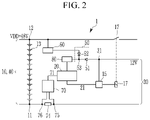
- FIG. 2 illustrates a power supply system 1 according to a second embodiment of the present disclosure.
- FIG. 1 the differences with respect to the embodiment shown in FIG. 1 will be primarily described. Elements and components that are the same or substantially the same between the embodiments shown in FIGS. 1 and 2 may not be described again.
- a switching unit 50 is configured to automatically select the power supply 30 , 40 with (e.g., outputting) the higher supply voltage.
- the switching unit 50 may include a first diode 51 , a second diode 52 , and an output node 53 .
- the first power supply 30 may be electrically connected to the anode of the first diode 51
- the second power supply 40 may be electrically connected to the anode of the second diode 52
- the output node 53 may be electrically connected to the cathode of each of the first and second diodes 51 , 52 .
- the output node 53 may be further electrically connected to the electronic unit 20 .
- the switching unit 50 shown in FIG. 1 the switching unit 50 shown in FIG. 2 automatically connects the power supply 30 , 40 having the higher voltage to the electronic unit 20 .
- the connected diodes 51 , 52 select or set the power supply 30 , 40 with the higher voltage to be conductive to the electronic unit 20 and disconnect or set the power supply 30 , 40 with the lower voltage non-conductive to the electronic unit 20 .
- the voltage applied to the anode of the second diode 52 coincides with the threshold voltage.
- this voltage may be set to about 5 V or slightly more, for example, about 5 V plus the voltage drop across the second diode 52 , but the present disclosure is not limited thereto.
- the threshold voltage may be between about 5 V and about 6 V, or between about 5 V and about 5.5 V, or between about 5 V and about 5.2 V.
- a voltage below about 5 V at the anode of the first diode 51 may set the first diode 51 into a non-conductive state because it is then reverse biased when about 5 V is applied to the anode of the second diode 52 .
- the switching unit 50 effectively disconnects the first power supply 30 while the second diode 52 is set conductive because it is then forward biased.
- the first power supply 30 e.g., the voltage applied to the anode of the second diode 52
- recovers to a voltage above the threshold voltage for example, after the cold crank time window
- the first diode 51 becomes forward biased and the second diode 52 becomes reverse biased.
- the switching unit 50 automatically disconnects the second power supply 40 and electrically connects the first power supply 30 to the electronic unit 20 when the voltage of the first power supply 30 recovers to above the threshold voltage. Therefore, the switching unit 50 shown in FIG. 2 automatically switches without requiring additional control units.
- the second diode 52 and/or the first diode 51 may be a low drop-out diode.
- Low drop-out diodes may also be referred to as active diodes.
- Low drop-out diodes have a reduced inner voltage drop such that voltage losses are reduced or even eliminated.
- FIG. 3 shows a power supply system 1 according to a third embodiment of the present disclosure.
- the differences with respect to the embodiments shown in FIGS. 1 and 2 will be primarily described below. Elements and components that are the same or substantially the same between the embodiments shown in FIGS. 1-3 may not be described again. Even though the following embodiment is described as including the switching unit 50 as described above with respect to FIG. 2 , it is clear that the following embodiment can also be combined with the features (e.g., the switching unit 50 ) as shown in FIG. 1 .
- the power supply system 1 may include the analog front-end chip (AFE) 70 .
- the AFE 70 is electrically connected to the first node 11 and the second node 12 of the battery cell stack 10 to measure and receive the voltage between the nodes 11 , 12 .
- the AFE 70 may receive cell voltages of individual battery cells 13 or sub stacks of the battery cell stack 10 . Therefore, first node 11 and second node 12 may have different positions within or on the battery cell stack 10 . In this embodiment, the first node 11 and the second node 12 are illustrated as being positioned at the respective ends of the battery cell stack 10 .
- the AFE 70 thus, receives the system voltage VDD, typically 48 V, but the present disclosure is not limited thereto.
- the AFE 70 may include an internal voltage regulator 72 .
- the internal voltage regulator 72 may be configured to reduce the received voltage to an output voltage lower than the input (or received) voltage.
- the output voltage of the internal voltage regulator 72 and, thus the output voltage of the AFE 70 may be at least about 5 V (e.g., exactly 5 V or slightly above 5 V) to compensate for a voltage loss at the second diode 52 .
- the voltage may be between about 5 V and about 6 V, between about 5 V and about 5.5 V, or between about 5 V and about 5.2 V.
- the AFE 70 may be configured to supply the output voltage to the second input of the switching unit 50 or, when applied to the embodiment described above with respect to FIG. 2 , to the anode of the second diode 52 .
- the internal voltage regulator 72 may be a low-dropout regulator, such as a transistor-Zener-diode regulator, which includes resistors, transistors, and a Zener-diode, but the present disclosure is not limited thereto and other voltage regulator implementations may be used.
- a transistor-Zener-diode regulator which includes resistors, transistors, and a Zener-diode
- the microprocessor 20 when the electronic unit 20 is the microprocessor 20 , the microprocessor 20 may be configured to switch into a low power consumption mode.
- the microprocessor 20 may switch into the low power consumption mode when it detects that the power or current supplied thereto has dropped below a threshold power or threshold current, respectively.
- the power supplied by the voltage regulator 72 of the AFE 70 may be weaker than an external voltage regulator 60 as in the embodiments shown in FIGS. 1 and 2 but may support smaller currents, for example, currents between about 5 mA and about 10 mA in a low power consumption mode.
- the low power consumption mode may be implementable by an application or computer program running on the microprocessor 20 , in one or more computing devices, executing computer program instructions and interacting with other system components for performing the various functionalities described herein.
- the computer program instructions may be stored in a memory, which may be implemented in a computing device using a standard memory device, such as, for example, a random access memory (RAM).
- RAM random access memory
- the electronic or electric devices and/or any other relevant devices or components according to embodiments of the present disclosure described herein may be implemented utilizing any suitable hardware, firmware (e.g., an application-specific integrated circuit), software, or a combination of software, firmware, and hardware.
- the various components of these devices may be formed on one integrated circuit (IC) chip or on separate IC chips.
- the various components of these devices may be implemented on a flexible printed circuit film, a tape carrier package (TCP), a printed circuit board (PCB), or formed on one substrate.
- the various components of these devices may be a process or thread, running on one or more processors, in one or more computing devices, executing computer program instructions and interacting with other system components for performing the various functionalities described herein.
- the computer program instructions are stored in a memory which may be implemented in a computing device using a standard memory device, such as, for example, a random access memory (RAM).
- the computer program instructions may also be stored in other non-transitory computer readable media such as, for example, a CD-ROM, flash drive, or the like.
- a person of skill in the art should recognize that the functionality of various computing devices may be combined or integrated into a single computing device, or the functionality of a particular computing device may be distributed across one or more other computing devices without departing from the scope of the exemplary embodiments of the present disclosure.
Landscapes
- Engineering & Computer Science (AREA)
- Power Engineering (AREA)
- Transportation (AREA)
- Mechanical Engineering (AREA)
- Sustainable Development (AREA)
- Sustainable Energy (AREA)
- Life Sciences & Earth Sciences (AREA)
- Business, Economics & Management (AREA)
- Emergency Management (AREA)
- Manufacturing & Machinery (AREA)
- Chemical & Material Sciences (AREA)
- Chemical Kinetics & Catalysis (AREA)
- Electrochemistry (AREA)
- General Chemical & Material Sciences (AREA)
- Charge And Discharge Circuits For Batteries Or The Like (AREA)
Abstract
Description
- 1 power supply system
- 10 battery cell stack
- 11 first node
- 12 second node
- 13 battery cell
- 15 switch control unit/relay control unit
- 17 power switch/relay
- 20 electronic unit/microprocessor
- 21 control line
- 30 first power supply
- 31 node
- 40 second power supply
- 50 switching unit
- 51 first diode
- 52 second diode
- 53 output node
- 60 voltage regulator
- 70 analog-front-end chip (AFE)
- 71 control line
- 72 internal voltage regulator
- 74 shunt
- 75 node
- 76 node
- 80 power supply regulator
Claims (20)
Applications Claiming Priority (5)
| Application Number | Priority Date | Filing Date | Title |
|---|---|---|---|
| EP19205225 | 2019-10-25 | ||
| EP19205225.6 | 2019-10-25 | ||
| EP19205225.6A EP3812205B1 (en) | 2019-10-25 | 2019-10-25 | Power supply system |
| KR10-2020-0110371 | 2020-08-31 | ||
| KR1020200110371A KR20210050441A (en) | 2019-10-25 | 2020-08-31 | Power supply system and including the same |
Publications (2)
| Publication Number | Publication Date |
|---|---|
| US20210126481A1 US20210126481A1 (en) | 2021-04-29 |
| US11476690B2 true US11476690B2 (en) | 2022-10-18 |
Family
ID=75586431
Family Applications (1)
| Application Number | Title | Priority Date | Filing Date |
|---|---|---|---|
| US17/009,325 Active US11476690B2 (en) | 2019-10-25 | 2020-09-01 | Power supply system |
Country Status (1)
| Country | Link |
|---|---|
| US (1) | US11476690B2 (en) |
Cited By (1)
| Publication number | Priority date | Publication date | Assignee | Title |
|---|---|---|---|---|
| EP4686028A3 (en) * | 2024-07-25 | 2026-04-15 | Samsung Sdi Co., Ltd. | Redundant power device |
Families Citing this family (4)
| Publication number | Priority date | Publication date | Assignee | Title |
|---|---|---|---|---|
| US20210249872A1 (en) * | 2020-02-06 | 2021-08-12 | Samsung Sdi Co., Ltd. | Battery system |
| CN115441740A (en) * | 2021-06-02 | 2022-12-06 | 超聚变数字技术有限公司 | Power supply module and electronic equipment |
| CN113659673B (en) * | 2021-08-13 | 2024-12-31 | 福建云众动力科技有限公司 | A fast charging and grid connection device based on energy storage power supply and its working method |
| CN117656835A (en) * | 2022-08-23 | 2024-03-08 | 优跑汽车技术(上海)有限公司 | Vehicle thermal runaway control system and vehicle |
Citations (55)
| Publication number | Priority date | Publication date | Assignee | Title |
|---|---|---|---|---|
| US20030085621A1 (en) | 1997-11-17 | 2003-05-08 | Potega Patrick Henry | Power supply methods and configurations |
| US6771188B2 (en) | 2000-05-17 | 2004-08-03 | Omega Patents, L.L.C. | Vehicle control system for controlling a vehicle function including a vehicle tracking unit and related methods |
| US6915192B2 (en) | 2003-01-17 | 2005-07-05 | Mitsubishi Denki Kabushiki Kaisha | Vehicular electronic control apparatus |
| US20050228562A1 (en) | 2004-04-12 | 2005-10-13 | Mitsubishi Denki Kabushiki Kaisha | Car-mounted electronic control device |
| US7119459B2 (en) | 2000-06-13 | 2006-10-10 | Azoteq (Pty) Ltd | Intelligent switch for connecting power to a load |
| US7251551B2 (en) | 2003-09-24 | 2007-07-31 | Mitsubishi Denki Kabushiki Kaisha | On-vehicle electronic control device |
| JP2007274866A (en) | 2006-03-31 | 2007-10-18 | Mitsumi Electric Co Ltd | Battery protection module and battery protection system |
| US7453235B2 (en) | 2000-02-18 | 2008-11-18 | Liebert Corporation | Modular uninterruptible power supply |
| US7683576B2 (en) | 2007-05-01 | 2010-03-23 | Jenn-Yang Tien | Smart lead acid battery charging/discharging management system |
| US20100209748A1 (en) | 2009-02-17 | 2010-08-19 | Hitachi, Ltd. | Battery System |
| US20110001357A1 (en) | 2009-01-06 | 2011-01-06 | Guoxing Li | Vertical bus circuits |
| US20110169450A1 (en) | 2009-07-14 | 2011-07-14 | Hudnall Coy A | Battery control apparatus |
| US8004238B2 (en) | 2008-05-28 | 2011-08-23 | Lg Chem, Ltd. | Apparatus for balancing of battery pack having function of prevention of over-discharge |
| US8018702B2 (en) | 2008-06-18 | 2011-09-13 | Mitsubishi Electric Corporation | Power supply abnormality detection circuit for on-vehicle electronic control device |
| US20120187887A1 (en) | 2011-01-21 | 2012-07-26 | Honda Motor Co., Ltd. | Power unit for electric vehicle |
| CN202435069U (en) | 2011-12-15 | 2012-09-12 | 东莞钜威新能源有限公司 | Battery management system and corresponding electronic system |
| US8602141B2 (en) | 2010-04-05 | 2013-12-10 | Daimler Trucks North America Llc | Vehicle power system with fuel cell auxiliary power unit (APU) |
| US20140028098A1 (en) | 2007-12-11 | 2014-01-30 | Antonio Trigiani | Battery management system for multicell batteries |
| US8669739B2 (en) | 2011-07-05 | 2014-03-11 | Fuji Jukogyo Kabushiki Kaisha | Electric charging system, electric vehicle and electric charger |
| WO2014098875A1 (en) | 2012-12-20 | 2014-06-26 | Powergenix Systems, Inc. | Controlling battery states of charge in systems having separate power sources |
| US20140181541A1 (en) | 2012-12-21 | 2014-06-26 | Hitachi, Ltd. | Information equipment and battery charge circuit |
| US8865328B2 (en) | 2010-06-09 | 2014-10-21 | Samsung Sdi Co., Ltd. | Battery protecting circuit, method of controlling the same, and battery pack |
| US8938323B2 (en) | 2010-02-25 | 2015-01-20 | Samsung Sdi Co., Ltd. | Power storage system and method of controlling the same |
| US9000718B2 (en) | 2011-02-21 | 2015-04-07 | Samsung Sdi Co., Ltd. | Battery management system including switch |
| US20150120129A1 (en) | 2013-10-24 | 2015-04-30 | Samsung Techwin Co., Ltd. | Method for controlling vehicle driving |
| US9030167B2 (en) | 2010-02-08 | 2015-05-12 | Sanyo Electric Co., Ltd. | Power source apparatus |
| US9054538B2 (en) | 2012-08-30 | 2015-06-09 | Samsung Sdi Co., Ltd. | Battery management system |
| EP2897250A1 (en) | 2014-01-15 | 2015-07-22 | Makita Corporation | Battery pack |
| CN104917215A (en) | 2014-03-13 | 2015-09-16 | 观致汽车有限公司 | Battery pack open circuit control system and battery pack and vehicle provided with same |
| EP2919346A1 (en) | 2013-10-07 | 2015-09-16 | LG Chem, Ltd. | Device and method for managing battery, including malfunction prevention algorithm |
| US9252462B2 (en) | 2011-05-18 | 2016-02-02 | Samsung Sdi Co., Ltd. | Battery management system |
| US9255957B2 (en) | 2012-08-14 | 2016-02-09 | Hitachi Automotive Systems, Ltd. | Earth fault detection circuit and power source device |
| US9397370B2 (en) | 1999-06-25 | 2016-07-19 | The Board Of Trustees Of The University Of Illinois | Single and multiple cell battery with built-in controller |
| US20160207418A1 (en) | 2015-01-21 | 2016-07-21 | Polaris Industries Inc. | Electric vehicle |
| US20160226107A1 (en) | 2014-08-26 | 2016-08-04 | Elite Power Innovations, Llc | Method and system for battery management |
| US20160352131A1 (en) | 2010-10-19 | 2016-12-01 | Larry Nelson | Apparatus and Method for Charging and Discharging a Multiple Battery System |
| US9544967B2 (en) | 2011-04-15 | 2017-01-10 | Wireless Environment, Llc | Lighting device capable of maintaining light intensity in demand response applications |
| US9748548B2 (en) | 2013-07-30 | 2017-08-29 | Johnson Controls Technology Company | Pouch frame with integral circuitry for battery module |
| US9851413B2 (en) | 2014-12-29 | 2017-12-26 | Samsung Electronics Co., Ltd. | Method and apparatus for estimating current |
| US20180186244A1 (en) | 2016-12-30 | 2018-07-05 | Textron Innovations Inc. | Charging a lithium battery on a utility vehicle |
| US20180212449A1 (en) | 2017-01-26 | 2018-07-26 | Samsung Electronics Co., Ltd. | Electronic device and operating method thereof |
| US20180254732A1 (en) | 2015-09-11 | 2018-09-06 | Invertedpower Pty Ltd | A controller for an inductive load having one or more inductive windings |
| US20180257506A1 (en) | 2014-11-14 | 2018-09-13 | Johnson Controls Technology Company | Semi-active partial parallel battery architecture for an automotive vehicle systems and methods |
| WO2018231573A1 (en) | 2017-06-15 | 2018-12-20 | A123 Systems Llc | System and method for operating a dual battery system |
| US10160326B2 (en) | 2016-07-05 | 2018-12-25 | Hyundai Motor Company | Apparatus for preventing overcharge of battery in eco-vehicle |
| WO2019111878A1 (en) | 2017-12-04 | 2019-06-13 | 株式会社Gsユアサ | Measurement device, storage device, measurement system, and method for measuring offset error |
| US10389144B2 (en) | 2016-02-25 | 2019-08-20 | Samsung Sdi Co., Ltd. | Battery protection circuit monitoring a state of a charging switch and battery pack including same |
| US20190372381A1 (en) * | 2018-06-01 | 2019-12-05 | Samsung Sdi Co., Ltd. | Battery system |
| US20200020992A1 (en) * | 2018-07-10 | 2020-01-16 | Samsung Sdi Co., Ltd. | Battery system |
| US20200119574A1 (en) * | 2018-10-16 | 2020-04-16 | Shaopei WANG | Charger circuit and intelligent charging control method thereof |
| US20200195033A1 (en) * | 2018-12-17 | 2020-06-18 | Subaru Corporation | Battery charge control apparatus for vehicle and method of controlling battery charging of vehicle |
| US20200313458A1 (en) * | 2019-03-27 | 2020-10-01 | Subaru Corporation | Electric power supply system |
| US10804717B1 (en) | 2017-12-05 | 2020-10-13 | Amazon Technologies, Inc. | Resettable battery disconnect device |
| US20210028503A1 (en) * | 2019-07-23 | 2021-01-28 | Cummins Inc. | Dc-dc-converter-based active voltage-balancing system and method for parallel battery packs |
| US20210143486A1 (en) | 2019-11-11 | 2021-05-13 | Samsung Sdi Co., Ltd. | Control unit for a battery system |
-
2020
- 2020-09-01 US US17/009,325 patent/US11476690B2/en active Active
Patent Citations (56)
| Publication number | Priority date | Publication date | Assignee | Title |
|---|---|---|---|---|
| US20030085621A1 (en) | 1997-11-17 | 2003-05-08 | Potega Patrick Henry | Power supply methods and configurations |
| US9397370B2 (en) | 1999-06-25 | 2016-07-19 | The Board Of Trustees Of The University Of Illinois | Single and multiple cell battery with built-in controller |
| US7453235B2 (en) | 2000-02-18 | 2008-11-18 | Liebert Corporation | Modular uninterruptible power supply |
| US6771188B2 (en) | 2000-05-17 | 2004-08-03 | Omega Patents, L.L.C. | Vehicle control system for controlling a vehicle function including a vehicle tracking unit and related methods |
| US7119459B2 (en) | 2000-06-13 | 2006-10-10 | Azoteq (Pty) Ltd | Intelligent switch for connecting power to a load |
| US6915192B2 (en) | 2003-01-17 | 2005-07-05 | Mitsubishi Denki Kabushiki Kaisha | Vehicular electronic control apparatus |
| US7251551B2 (en) | 2003-09-24 | 2007-07-31 | Mitsubishi Denki Kabushiki Kaisha | On-vehicle electronic control device |
| US20050228562A1 (en) | 2004-04-12 | 2005-10-13 | Mitsubishi Denki Kabushiki Kaisha | Car-mounted electronic control device |
| JP2007274866A (en) | 2006-03-31 | 2007-10-18 | Mitsumi Electric Co Ltd | Battery protection module and battery protection system |
| US7683576B2 (en) | 2007-05-01 | 2010-03-23 | Jenn-Yang Tien | Smart lead acid battery charging/discharging management system |
| US20140028098A1 (en) | 2007-12-11 | 2014-01-30 | Antonio Trigiani | Battery management system for multicell batteries |
| US8004238B2 (en) | 2008-05-28 | 2011-08-23 | Lg Chem, Ltd. | Apparatus for balancing of battery pack having function of prevention of over-discharge |
| US8018702B2 (en) | 2008-06-18 | 2011-09-13 | Mitsubishi Electric Corporation | Power supply abnormality detection circuit for on-vehicle electronic control device |
| US20110001357A1 (en) | 2009-01-06 | 2011-01-06 | Guoxing Li | Vertical bus circuits |
| US20100209748A1 (en) | 2009-02-17 | 2010-08-19 | Hitachi, Ltd. | Battery System |
| US20110169450A1 (en) | 2009-07-14 | 2011-07-14 | Hudnall Coy A | Battery control apparatus |
| US9030167B2 (en) | 2010-02-08 | 2015-05-12 | Sanyo Electric Co., Ltd. | Power source apparatus |
| US8938323B2 (en) | 2010-02-25 | 2015-01-20 | Samsung Sdi Co., Ltd. | Power storage system and method of controlling the same |
| US8602141B2 (en) | 2010-04-05 | 2013-12-10 | Daimler Trucks North America Llc | Vehicle power system with fuel cell auxiliary power unit (APU) |
| US8865328B2 (en) | 2010-06-09 | 2014-10-21 | Samsung Sdi Co., Ltd. | Battery protecting circuit, method of controlling the same, and battery pack |
| US20160352131A1 (en) | 2010-10-19 | 2016-12-01 | Larry Nelson | Apparatus and Method for Charging and Discharging a Multiple Battery System |
| US20120187887A1 (en) | 2011-01-21 | 2012-07-26 | Honda Motor Co., Ltd. | Power unit for electric vehicle |
| US9000718B2 (en) | 2011-02-21 | 2015-04-07 | Samsung Sdi Co., Ltd. | Battery management system including switch |
| US9544967B2 (en) | 2011-04-15 | 2017-01-10 | Wireless Environment, Llc | Lighting device capable of maintaining light intensity in demand response applications |
| US9252462B2 (en) | 2011-05-18 | 2016-02-02 | Samsung Sdi Co., Ltd. | Battery management system |
| US8669739B2 (en) | 2011-07-05 | 2014-03-11 | Fuji Jukogyo Kabushiki Kaisha | Electric charging system, electric vehicle and electric charger |
| CN202435069U (en) | 2011-12-15 | 2012-09-12 | 东莞钜威新能源有限公司 | Battery management system and corresponding electronic system |
| US9255957B2 (en) | 2012-08-14 | 2016-02-09 | Hitachi Automotive Systems, Ltd. | Earth fault detection circuit and power source device |
| US9054538B2 (en) | 2012-08-30 | 2015-06-09 | Samsung Sdi Co., Ltd. | Battery management system |
| WO2014098875A1 (en) | 2012-12-20 | 2014-06-26 | Powergenix Systems, Inc. | Controlling battery states of charge in systems having separate power sources |
| US20140181541A1 (en) | 2012-12-21 | 2014-06-26 | Hitachi, Ltd. | Information equipment and battery charge circuit |
| US9748548B2 (en) | 2013-07-30 | 2017-08-29 | Johnson Controls Technology Company | Pouch frame with integral circuitry for battery module |
| EP2919346A1 (en) | 2013-10-07 | 2015-09-16 | LG Chem, Ltd. | Device and method for managing battery, including malfunction prevention algorithm |
| US20150120129A1 (en) | 2013-10-24 | 2015-04-30 | Samsung Techwin Co., Ltd. | Method for controlling vehicle driving |
| EP2897250A1 (en) | 2014-01-15 | 2015-07-22 | Makita Corporation | Battery pack |
| CN104917215A (en) | 2014-03-13 | 2015-09-16 | 观致汽车有限公司 | Battery pack open circuit control system and battery pack and vehicle provided with same |
| US20160226107A1 (en) | 2014-08-26 | 2016-08-04 | Elite Power Innovations, Llc | Method and system for battery management |
| US20180257506A1 (en) | 2014-11-14 | 2018-09-13 | Johnson Controls Technology Company | Semi-active partial parallel battery architecture for an automotive vehicle systems and methods |
| US9851413B2 (en) | 2014-12-29 | 2017-12-26 | Samsung Electronics Co., Ltd. | Method and apparatus for estimating current |
| US20160207418A1 (en) | 2015-01-21 | 2016-07-21 | Polaris Industries Inc. | Electric vehicle |
| US20180254732A1 (en) | 2015-09-11 | 2018-09-06 | Invertedpower Pty Ltd | A controller for an inductive load having one or more inductive windings |
| US10389144B2 (en) | 2016-02-25 | 2019-08-20 | Samsung Sdi Co., Ltd. | Battery protection circuit monitoring a state of a charging switch and battery pack including same |
| US10160326B2 (en) | 2016-07-05 | 2018-12-25 | Hyundai Motor Company | Apparatus for preventing overcharge of battery in eco-vehicle |
| US20180186244A1 (en) | 2016-12-30 | 2018-07-05 | Textron Innovations Inc. | Charging a lithium battery on a utility vehicle |
| US20180212449A1 (en) | 2017-01-26 | 2018-07-26 | Samsung Electronics Co., Ltd. | Electronic device and operating method thereof |
| WO2018231573A1 (en) | 2017-06-15 | 2018-12-20 | A123 Systems Llc | System and method for operating a dual battery system |
| WO2019111878A1 (en) | 2017-12-04 | 2019-06-13 | 株式会社Gsユアサ | Measurement device, storage device, measurement system, and method for measuring offset error |
| US10804717B1 (en) | 2017-12-05 | 2020-10-13 | Amazon Technologies, Inc. | Resettable battery disconnect device |
| US20190372381A1 (en) * | 2018-06-01 | 2019-12-05 | Samsung Sdi Co., Ltd. | Battery system |
| US20200020992A1 (en) * | 2018-07-10 | 2020-01-16 | Samsung Sdi Co., Ltd. | Battery system |
| US20200119574A1 (en) * | 2018-10-16 | 2020-04-16 | Shaopei WANG | Charger circuit and intelligent charging control method thereof |
| US20200195033A1 (en) * | 2018-12-17 | 2020-06-18 | Subaru Corporation | Battery charge control apparatus for vehicle and method of controlling battery charging of vehicle |
| US20200313458A1 (en) * | 2019-03-27 | 2020-10-01 | Subaru Corporation | Electric power supply system |
| US11173793B2 (en) * | 2019-03-27 | 2021-11-16 | Subaru Corporation | Electric power supply system including battery, switching apparatus and control apparatus |
| US20210028503A1 (en) * | 2019-07-23 | 2021-01-28 | Cummins Inc. | Dc-dc-converter-based active voltage-balancing system and method for parallel battery packs |
| US20210143486A1 (en) | 2019-11-11 | 2021-05-13 | Samsung Sdi Co., Ltd. | Control unit for a battery system |
Non-Patent Citations (9)
| Title |
|---|
| European Communication pursuant to Article 94(3) EPC, for Patent Application No. 19 205 225.6, dated May 23, 2022, 7 pages. |
| Ex Parte Quayle action from USPTO for U.S. Appl. No. 16/367,015, mailed Jul. 9, 2021, 6 pages. |
| Extended European Search Report issued in EP Application No. 19205225.6, dated May 4, 2020, 10 pages. |
| Extended European Search Report, European Application No. 18182603.3, dated Jan. 24, 2019, 7 pages. |
| Notice of Allowance from USPTO for U.S. Appl. No. 16/367,015, dated Feb. 10, 2022, 5 pages. |
| Notice of Allowance from USPTO for U.S. Appl. No. 16/367,015, dated Sep. 17, 2021, 14 pages. |
| Notice of Allowance issued in U.S. Appl. No. 16/367,015, dated Jun. 2, 2022, 8 pages. |
| Office action from USPTO for U.S. Appl. No. 16/367,015, dated Mar. 26, 2021, 15 pages. |
| Restriction Requirement from USPTO for U.S. Appl. No. 16/367,015, dated Jan. 8, 2021, 7 pages. |
Cited By (1)
| Publication number | Priority date | Publication date | Assignee | Title |
|---|---|---|---|---|
| EP4686028A3 (en) * | 2024-07-25 | 2026-04-15 | Samsung Sdi Co., Ltd. | Redundant power device |
Also Published As
| Publication number | Publication date |
|---|---|
| US20210126481A1 (en) | 2021-04-29 |
Similar Documents
| Publication | Publication Date | Title |
|---|---|---|
| US11476690B2 (en) | Power supply system | |
| KR102816659B1 (en) | Battery system | |
| US11407311B2 (en) | Dual power supply system | |
| US11247582B2 (en) | Control electronics for a battery system, method for power supplying control electronics for a battery system, battery system and vehicle | |
| US11084397B2 (en) | Power supply system for vehicle with multiple operating voltages | |
| EP3722137B1 (en) | Control electronics for a battery system, method for power supplying control electronics for a battery system, battery system and vehicle | |
| KR102607450B1 (en) | Power supply system | |
| US11063460B2 (en) | Battery system | |
| KR102455617B1 (en) | An electric-vehicle battery system comprising a real time clock | |
| US11223213B2 (en) | Battery system and electric vehicle using the same | |
| EP3863141A1 (en) | Battery system | |
| US11329564B2 (en) | Control system for a battery system | |
| US20210249872A1 (en) | Battery system | |
| EP3812205B1 (en) | Power supply system | |
| US11884182B2 (en) | Electric-vehicle battery system including a real time clock | |
| US11420533B2 (en) | Battery system | |
| US11444337B2 (en) | Solid state switch driver circuit for a battery system | |
| KR20220170352A (en) | Bidirectional power supply system for powering a battery management system of an electric vehicle | |
| KR20210122680A (en) | Battery system and vehicle including the same | |
| EP3708403B1 (en) | Solid state switch driver circuit for a battery system |
Legal Events
| Date | Code | Title | Description |
|---|---|---|---|
| AS | Assignment |
Owner name: SAMSUNG SDI CO., LTD., KOREA, REPUBLIC OF Free format text: ASSIGNMENT OF ASSIGNORS INTEREST;ASSIGNORS:KURCIK, PETER;HOFER, MAXIMILIAN;PRETSCHUH, MARKUS;AND OTHERS;SIGNING DATES FROM 20200719 TO 20200803;REEL/FRAME:053666/0473 |
|
| FEPP | Fee payment procedure |
Free format text: ENTITY STATUS SET TO UNDISCOUNTED (ORIGINAL EVENT CODE: BIG.); ENTITY STATUS OF PATENT OWNER: LARGE ENTITY |
|
| STPP | Information on status: patent application and granting procedure in general |
Free format text: APPLICATION DISPATCHED FROM PREEXAM, NOT YET DOCKETED |
|
| STPP | Information on status: patent application and granting procedure in general |
Free format text: DOCKETED NEW CASE - READY FOR EXAMINATION |
|
| STPP | Information on status: patent application and granting procedure in general |
Free format text: NON FINAL ACTION MAILED |
|
| STPP | Information on status: patent application and granting procedure in general |
Free format text: RESPONSE TO NON-FINAL OFFICE ACTION ENTERED AND FORWARDED TO EXAMINER |
|
| STPP | Information on status: patent application and granting procedure in general |
Free format text: NOTICE OF ALLOWANCE MAILED -- APPLICATION RECEIVED IN OFFICE OF PUBLICATIONS |
|
| STPP | Information on status: patent application and granting procedure in general |
Free format text: DOCKETED NEW CASE - READY FOR EXAMINATION |
|
| STPP | Information on status: patent application and granting procedure in general |
Free format text: NOTICE OF ALLOWANCE MAILED -- APPLICATION RECEIVED IN OFFICE OF PUBLICATIONS |
|
| STPP | Information on status: patent application and granting procedure in general |
Free format text: AWAITING TC RESP, ISSUE FEE PAYMENT VERIFIED Free format text: PUBLICATIONS -- ISSUE FEE PAYMENT VERIFIED |
|
| STCF | Information on status: patent grant |
Free format text: PATENTED CASE |
|
| CC | Certificate of correction | ||
| MAFP | Maintenance fee payment |
Free format text: PAYMENT OF MAINTENANCE FEE, 4TH YEAR, LARGE ENTITY (ORIGINAL EVENT CODE: M1551); ENTITY STATUS OF PATENT OWNER: LARGE ENTITY Year of fee payment: 4 |