US11475683B2 - Object classification system and method - Google Patents
Object classification system and method Download PDFInfo
- Publication number
- US11475683B2 US11475683B2 US16/616,152 US201816616152A US11475683B2 US 11475683 B2 US11475683 B2 US 11475683B2 US 201816616152 A US201816616152 A US 201816616152A US 11475683 B2 US11475683 B2 US 11475683B2
- Authority
- US
- United States
- Prior art keywords
- classification system
- cavity
- object classification
- mixing
- mixing unit
- Prior art date
- Legal status (The legal status is an assumption and is not a legal conclusion. Google has not performed a legal analysis and makes no representation as to the accuracy of the status listed.)
- Active, expires
Links
Images


Classifications
-
- G—PHYSICS
- G06—COMPUTING OR CALCULATING; COUNTING
- G06N—COMPUTING ARRANGEMENTS BASED ON SPECIFIC COMPUTATIONAL MODELS
- G06N3/00—Computing arrangements based on biological models
- G06N3/02—Neural networks
- G06N3/06—Physical realisation, i.e. hardware implementation of neural networks, neurons or parts of neurons
- G06N3/067—Physical realisation, i.e. hardware implementation of neural networks, neurons or parts of neurons using optical means
- G06N3/0675—Physical realisation, i.e. hardware implementation of neural networks, neurons or parts of neurons using optical means using electro-optical, acousto-optical or opto-electronic means
-
- G—PHYSICS
- G01—MEASURING; TESTING
- G01N—INVESTIGATING OR ANALYSING MATERIALS BY DETERMINING THEIR CHEMICAL OR PHYSICAL PROPERTIES
- G01N21/00—Investigating or analysing materials by the use of optical means, i.e. using sub-millimetre waves, infrared, visible or ultraviolet light
- G01N21/17—Systems in which incident light is modified in accordance with the properties of the material investigated
- G01N21/47—Scattering, i.e. diffuse reflection
-
- G—PHYSICS
- G01—MEASURING; TESTING
- G01N—INVESTIGATING OR ANALYSING MATERIALS BY DETERMINING THEIR CHEMICAL OR PHYSICAL PROPERTIES
- G01N33/00—Investigating or analysing materials by specific methods not covered by groups G01N1/00 - G01N31/00
- G01N33/48—Biological material, e.g. blood, urine; Haemocytometers
-
- G—PHYSICS
- G02—OPTICS
- G02B—OPTICAL ELEMENTS, SYSTEMS OR APPARATUS
- G02B6/00—Light guides; Structural details of arrangements comprising light guides and other optical elements, e.g. couplings
- G02B6/10—Light guides; Structural details of arrangements comprising light guides and other optical elements, e.g. couplings of the optical waveguide type
- G02B6/12—Light guides; Structural details of arrangements comprising light guides and other optical elements, e.g. couplings of the optical waveguide type of the integrated circuit kind
- G02B6/122—Basic optical elements, e.g. light-guiding paths
- G02B6/1225—Basic optical elements, e.g. light-guiding paths comprising photonic band-gap structures or photonic lattices
-
- G—PHYSICS
- G02—OPTICS
- G02B—OPTICAL ELEMENTS, SYSTEMS OR APPARATUS
- G02B6/00—Light guides; Structural details of arrangements comprising light guides and other optical elements, e.g. couplings
- G02B6/10—Light guides; Structural details of arrangements comprising light guides and other optical elements, e.g. couplings of the optical waveguide type
- G02B6/12—Light guides; Structural details of arrangements comprising light guides and other optical elements, e.g. couplings of the optical waveguide type of the integrated circuit kind
- G02B6/122—Basic optical elements, e.g. light-guiding paths
- G02B6/1228—Tapered waveguides, e.g. integrated spot-size transformers
-
- G—PHYSICS
- G06—COMPUTING OR CALCULATING; COUNTING
- G06V—IMAGE OR VIDEO RECOGNITION OR UNDERSTANDING
- G06V10/00—Arrangements for image or video recognition or understanding
- G06V10/10—Image acquisition
- G06V10/12—Details of acquisition arrangements; Constructional details thereof
- G06V10/14—Optical characteristics of the device performing the acquisition or on the illumination arrangements
- G06V10/145—Illumination specially adapted for pattern recognition, e.g. using gratings
-
- G—PHYSICS
- G06—COMPUTING OR CALCULATING; COUNTING
- G06V—IMAGE OR VIDEO RECOGNITION OR UNDERSTANDING
- G06V20/00—Scenes; Scene-specific elements
- G06V20/60—Type of objects
- G06V20/69—Microscopic objects, e.g. biological cells or cellular parts
- G06V20/693—Acquisition
-
- G—PHYSICS
- G06—COMPUTING OR CALCULATING; COUNTING
- G06V—IMAGE OR VIDEO RECOGNITION OR UNDERSTANDING
- G06V20/00—Scenes; Scene-specific elements
- G06V20/60—Type of objects
- G06V20/69—Microscopic objects, e.g. biological cells or cellular parts
- G06V20/698—Matching; Classification
-
- H—ELECTRICITY
- H04—ELECTRIC COMMUNICATION TECHNIQUE
- H04N—PICTORIAL COMMUNICATION, e.g. TELEVISION
- H04N25/00—Circuitry of solid-state image sensors [SSIS]; Control thereof
-
- H04N5/335—
-
- G—PHYSICS
- G01—MEASURING; TESTING
- G01N—INVESTIGATING OR ANALYSING MATERIALS BY DETERMINING THEIR CHEMICAL OR PHYSICAL PROPERTIES
- G01N2201/00—Features of devices classified in G01N21/00
- G01N2201/06—Illumination; Optics
- G01N2201/061—Sources
- G01N2201/06113—Coherent sources; lasers
-
- G—PHYSICS
- G01—MEASURING; TESTING
- G01N—INVESTIGATING OR ANALYSING MATERIALS BY DETERMINING THEIR CHEMICAL OR PHYSICAL PROPERTIES
- G01N2201/00—Features of devices classified in G01N21/00
- G01N2201/10—Scanning
Definitions
- the invention relates to the field of optical wave-based computing. More specifically it relates to methods and systems for optical wave-based computing with low loss using a mixing unit.
- Reservoir Computer specifically designed for efficient optical computation.
- Reservoir Computing is a machine learning branch focusing on processing of time-dependent data. It was first proposed in the early 2000s as a way of using an untrained neural network with internal feedback combined with a trained linear readout layer to perform classification of temporal data. The feedback through the nonlinear nodes in the so-called recurrent network performs a nonlinear mixing of the signal and provides a fading memory to the system.
- Passive photonic reservoirs may be used for a variety of applications. Nevertheless, the complexity of tasks the reservoir can perform depends on the number of neurons it consists of, these losses also limit the complexity of tasks that can be performed, and consequently there is still room for improvement.
- the present invention relates to an object classification system for classifying objects, the object classification system comprising an imaging region adapted for irradiating an object of interest, an arrayed detector, and a mixing unit configured for mixing the irradiation stemming from the object of interest by reflecting or scattering on average at least three times the irradiation after its interaction with the object of interest and prior to said detection.
- the mixing unit may be configured for reflecting or scattering on average at least five times, e.g. on average at least ten times the irradiation after its interaction with the object of interest.
- the mixing unit may comprise a plurality of scatterers.
- the mixing unit also may be a cavity with reflective walls comprising an input and a plurality of outputs. Examples thereof are also described further.
- this may include the situation wherein a lot of different parts of the radiation coming from the object are reflected or scattered in different ways.
- this may be formulated as at least once a significant part of the irradiation is reflected or scattered, whereby a significant part may be at least one fifth of the total light forward scattered by the object.
- scatterers are placed in layers, the complex scattering or reflecting condition or the condition that on average at least N times the irradiation is scattered or reflected, this thus includes an embodiment wherein a single layer of scatterers is used, whereby at different spatial positions the radiation will be scattered differently at different positions.
- the system further may comprise a classifier for classifying the objects based on the irradiation obtained after said mixing.
- the classifier may be a linear classifier or may be a more complex classifier, such as for example a feedforward neural network.
- the arrayed detector may be a line scan image sensor.
- the linear classifier may be implemented in the electrical field, receiving input signals from the line scan image sensor.
- the linear classifier may be based on a weighted sum of the input signals.
- the mixing unit may comprise a random set of scattering objects.
- the scattering objects may be scattering pillars.
- the random set of scattering objects may be positioned in a cavity.
- the scattering objects may be arranged in a plurality of layers, each layer comprising a row of randomly positioned scattering objects.
- the mixing unit may comprise a cavity which may be formed from silicon nitride and the scattering pillars being made of silica.
- the mixing unit may be a photonic crystal cavity.
- the mixing unit may be a cavity made in silicon, whereby ferroelectric thin films are coated on the cavity.
- the mixing unit may be a photonic crystal cavity made of silicon rods wherein in the middle nonlinear polymers are introduced.
- the mixing unit may comprise a cavity being made in a III-V material.
- the system may comprise a plurality of mixing units coupled in a hierarchical arrangement.
- the mixing units being coupled in a hierarchical arrangement may comprise a first mixing unit taking care of lower-level features in the input signal and further mixing units for taking care of higher-level features.
- the imaging region adapted for irradiating an object of interest may comprise a microfluidic channel for carrying the object in a fluid.
- the system may be a cell classification system.
- the present invention also relates to the use of an object classification system for classifying cells.
- the present invention further relates to a method for classifying objects, the method comprising irradiating an object of interest, mixing the irradiation after interacting with the object of interest and prior to the detection of the irradiation in the detector by reflecting or scattering on average at least three times using a mixing unit, and detecting the mixed irradiation with an arrayed detector.
- the method may comprise applying a linear classification of the detected mixed irradiation.
- the mixing may comprise mixing a static, non-time dependent irradiation signal, detecting said mixed signal and deriving therefrom a classification for the object of interest.
- the present invention relates to a passive photonics wave-based computing system configured for performing wave-based computing, the system comprising a mixing unit comprising at least one input and a plurality of outputs, the mixing unit further being configured for reflecting or scattering in a complex way of an optical beam received via said at least one input towards at least one of said plurality of outputs.
- the mixing element may be a photonic crystal cavity or may be a scattering based mixing unit. It is to be noted that the mixing unit typically may be substantially larger than the wavelength or than the order of the wavelength. The mixing unit may be at least larger than 5 times the wavelength with which the system will be used.
- the at least one input may be a plurality of inputs.
- the mixing unit has a plurality of outputs. Such outputs may be combined, e.g. using weighing and summing, such that the overall wave-based computing system may only have a single output.
- the mixing unit allows to provide good mixing of input radiation, without large losses occurring.
- the latter is obtained by avoiding at least some combiners and splitters in the system and instead using a mixing unit.
- a cavity reference is made to a region in the photonics device, that is typically filled with transparent materials, being transparent for the wavelengths of the radiation for which the system can be used and that comprises reflective elements at the edge, e.g. reflective walls.
- the mixing unit may be configured in the passive photonics wave-based computing system so that it acts as a fading memory for the radiation signals.
- the mixing unit may be a cavity comprising a plurality of reflective walls such that after a plurality of reflections radiation from the inputs eventually will reach an output port.
- the mixing unit may be a photonic crystal cavity.
- the mixing unit may have a shape of a quarter-stadium.
- the input and/or output waveguides may be connected to the mixing unit through adiabatic tapers.
- the mixing unit may be a cavity made in silicon, whereby ferroelectric thin films are coated on the cavity, wherein the mixing unit is a photonic crystal cavity made of silicon rods wherein in the middle nonlinear polymers are introduced, or wherein the cavity is made in a III-V material.
- the system may comprise a plurality of mixing units coupled in a hierarchical arrangement.
- the mixing units being coupled in a hierarchical arrangement may for example comprise a first mixing unit taking care of lower-level features in the input signal and the further cavity(ies) for taking care of higher-level features.
- the mixing unit may comprise a random set of scattering objects.
- the scattering objects may be scattering pillars.
- the random set of scattering objects may be positioned in a cavity.
- the cavity may be formed from silicon nitride and the scattering pillars may be made of silica.
- the present invention also relates to a method for performing photonic wave-based computing, the method comprising applying an optical input signal to one or more inputs of a mixing unit, allowing the optical signal to propagate in the mixing unit, said propagating comprising complicated reflecting or scattering of said optical signal received via said at least one input towards at least one of a plurality of outputs, and thus obtaining a nonlinear readout in at least one of said plurality of outputs.
- the nonlinear readout is obtained after being detected by the detector.
- the method performed is strictly speaking not a traditional reservoir computing technique but rather a sort of spatial variant of the concept, since the inputs, are static.
- typically no time-dependent signals are used.
- the method furthermore may comprise sampling the signals at discrete time intervals to combine the signals in a single output signal.
- FIG. 1 illustrates a mixing unit comprising a photonic crystal cavity with a plurality of input and output connectors, according to an embodiment of the present invention.
- FIG. 2 a and FIG. 2 b illustrate the pulse decay for a cavity with 9 respectively 5 connected waveguides, according to embodiments of the present invention.
- FIG. 3 illustrates the harmonical decay of the Q factor and T 1/2 with increasing number of exit waveguides, according to embodiments of the present invention.
- FIG. 4 illustrates sampling of the detected signal at discrete time intervals according to embodiments of the present invention.
- FIG. 5 illustrates a mixing unit comprising a plurality of scatterers according to an embodiment of the present invention.
- FIGS. 6 a to 6 c illustrates the effect of scatterers on an incoming radiation signal, according to an exemplary embodiment of the present invention.
- FIG. 7 illustrates the BER as function of the delay.
- FIG. 8 a describes the error for 9 connected waveguides vs. 5 connected waveguides.
- FIG. 9 a illustrates that the wave-based computing system can distinguish up to 4 bits without error and FIG. 9 b illustrates that for a header of length of 5 bits, the average error rate per header is still well below 5%, illustrating advantages of embodiments of the present invention.
- FIG. 10 illustrates a Linear Discriminant Analysis used to discern different headers, as can be used in embodiments of the present invention.
- FIG. 11 a and FIG. 11 b illustrate test and training errors of the classification without scatterers and with added noise ( FIG. 11 a ) and with 4 layers of scatterers and with added noise ( FIG. 11 b ), illustrating features of embodiments of the present invention.
- FIG. 12 a and FIG. 12 b illustrate test and training errors of the classification without scatterers and without added noise ( FIG. 12 a ) and with 4 layers of scatterers and without added noise ( FIG. 12 b ), illustrating features of embodiments of the present invention.
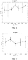
- FIG. 13 to FIG. 17 illustrate test errors as function of the random displacement amplitude of the silica scatters for respectively a 1, 2, 3, 4 or 5 layer configuration, according to embodiments of the present invention.
- FIGS. 18 a and 18 b illustrate the change in the acquired hologram due to small increases of the nucleus size for different wavelengths ( FIG. 18 a ) as well as optical losses on the collected far-field intensity due to the scatterers presence as function of cell nucleus size for different wavelengths ( FIG. 18 b ) illustrating features of embodiments of the present invention.
- FIG. 19 a and FIG. 19 b illustrate test and training errors of the classification without scatterers and with added noise ( FIG. 19 a ) and with 4 layers of scatterers and with added noise ( FIG. 19 b ), for wavelength 337.1 nm illustrating features of embodiments of the present invention.
- FIG. 20 a and FIG. 20 b illustrate test and training errors of the classification without scatterers and without added noise ( FIG. 20 a ) and with 4 layers of scatterers and without added noise ( FIG. 20 b ), for wavelength 337.1 nm illustrating features of embodiments of the present invention.
- the present invention relates to an object classification system for classifying objects, the object classification system comprising an imaging region adapted for irradiating an object of interest, an arrayed detector and a mixing unit configured for mixing the irradiation stemming from the object of interest by reflecting or scattering on average at least three times the irradiation after its interaction with the object of interest and prior to said detection.
- the object classification system advantageously also comprises a classifier for classifying the objects based on the irradiation obtained after said mixing.
- the classifier may be a linear classifier or a more complex classifier. Further in the description, by way of illustration, an exemplary object classification system will be described and simulated, thus showing standard and optional features and advantages of the object classification systems according to embodiments of the present invention.
- the type of mixing unit may be based on scatterers and/or may be based on a cavity with reflective walls. Such mixing units may correspond with mixing units as disclosed for the passive photonics wave-based computing systems described in the further aspects of the present description.
- Features and advantages may be applied to the object classification system mutates mutandis.
- the present invention also relates to the use of an object classification system for classifying objects, such as for example cells.
- the object classification system may be applied for performing distinguishing between healthy cells and non-healthy cells, such as for example cancerous cells.
- embodiments are not limited thereto and other applications also are envisaged, such as for example classification or detection of different types of biological cells (e.g. blood cells), different types of microparticles (also of non-organic nature), different types of flowing fluids, distinguishing between particles of different sizes and/or different composition, etc.
- the present invention relates to a method for classifying objects, the method comprising irradiating an object of interest, mixing the irradiation after interacting with the object of interest by reflecting or scattering at least three times using a mixing unit, and detecting the mixed irradiation with an arrayed detector.
- This may mean that at least three portions of the irradiation may be reflected in a different way and/or that a same portion of the irradiation may be subsequently reflected three times.
- the mixing may comprise mixing a static, non-time dependent irradiation signal, detecting said mixed signal and deriving therefrom a classification for the object of interest.
- the method also may comprise applying a classification, e.g. linear or more complex, of the detected mixed irradiation. More generally, the method also may comprise applying non-linear postprocessing. Further method steps may correspond with the functionality of the features of the device aspects described in this description.
- the present invention relates to a passive photonics wave-based computing system configured for performing wave-based computing.
- the wave-based computing has similarities with reservoir computing. Nevertheless, use may be made of time independent signals whereas for reservoir computing typically time dependent signals are used.
- the system comprises a mixing unit having at least one input and a plurality of outputs. It is to be noted that whereas the mixing unit typically has a plurality of outputs, the overall wave-based computing system may have a single output, whereby e.g. the single output of the overall system is obtained by combining, e.g. summing, weighted signals from the outputs of the mixing unit.
- the mixing unit furthermore is configured for complicated reflecting or scattering of an optical signal received via said at least one input towards at least one of said plurality of outputs.
- the wave-based computing system may be implemented in a plurality of ways. Two particular implementations will be described, one implementation whereby the mixing unit is based on a photonic crystal cavity comprising reflective walls for reflecting in a complex way an optical signal received via at least one input and a second implementation whereby the mixing is based on a plurality of scattering elements, e.g. pillars. Examples of both types of implementations will be described below, embodiments not being limited thereto.
- the wave-based computing system may, besides a mixing unit comprising at least one input and a plurality of outputs also comprise a readout layer for processing the output of the mixing unit, as well as a further output for outputting a result of the system.
- the computing system may comprise a non-linearity.
- the computing system also may comprise a static memory, implemented optically or in a hybrid opto-electronic way.
- FIG. 1 shows a schematic drawing of a mixing unit comprising a photonic crystal based cavity together with a plurality of input and output connectors.
- a cavity 12 is designed and optimized as the mixing unit 1 of the passive photonics wave-based computing system so that good mixing of the inputs is achieved, e.g. through an effective randomization of the propagating wave direction inside the cavity 12 after a large number of reflections 13 .
- the cavity shape typically displays curved features, for example the arc of a quarter-stadium cavity, but many other cavity shapes may be considered as mixing unit too.
- a quarter-stadium design may display 30 ⁇ m and 15 ⁇ m long semi-axis, however these numbers can vary according to a particular task to be solved and the required speed of the input signals.
- High reflectivity from the enclosing boundary 11 walls of the cavity may be obtained by the use of a photonic crystal structure comprising a regular lattice of air holes in silicon, but is not limited thereto and other material interfaces of the cavity walls may be conceived.
- Propagation losses, scattering losses, surface losses, and other sources of imperfections in the material and fabrication are typically small compared to the coupling losses induced by the plurality of input and output ports 10 connected to the cavity.
- the number of input and output connectors 10 constitutes the major control variable of the cavity's quality factor (Q-factor).
- the Q-factor is related to the lifetime of a cavity 12 excitation through one or more of its input connectors 10 ; the final decay of any excitation through loss mechanisms provides a form of fading memory to the passive photonic computing system.
- a reasonable minimum number of input and output connectors to perform computational tasks with low error rates is typically ranging between five and nine, corresponding to Q-factors between 3000 and 5000, but different choices may lead to better results in some cases.
- a higher Q-factor can be obtained by reducing the number of input and output connectors which gives rise to better system memory but trades system bandwidth.
- the input connectors 10 can serve as output connectors at the same time, thus limiting the complexity of the overall system.
- the input or output connectors 10 typically comprise of an adiabatically controlled taper 101 connecting to the external input or output waveguides and a defect waveguide 102 inside the photonic crystal structure, both ensuring that input and output radiation signals are delivered to and coupled out from the cavity 12 .
- the tapered sections 101 can be tailored to inject or extract a given fraction of the incident radiation signal, hence are another means to control the cavity's Q-factor. Typical transmissivity values range from 30% to 95%, but can be adapted accordingly and on an individual basis.
- an embodiment of the present invention may benefit from the flat surface structure of the cavity 12 which is ideally suited for deposition of thin film coatings, e.g. ferroelectric thin films but not limited thereto.
- a cavity region 12 based on air surrounded by photonic crystal walls made from silicon rods is an embodiment of the present invention that could be filled with a nonlinear material, nonlinear polymers for instance.
- Another possibility is to pattern the cavity 12 into a III-IV material. All the mentioned optional features provide an enhanced nonlinear response to the mixing unit 1 which may lead to increased efficiency or computational power of the passive photonic computing system.
- FIG. 1 By way of illustration, further features and characteristics will be described with reference to FIG. 1 .
- the particular quarter-stadium shape shown typically shows interesting dynamics and results in complete mixing of the fields, in the sense that an input wave will obtain all possible wave-vectors in the cavity.
- the mixing unit behaves like a fading memory necessary for wave-based computing.
- the lifetime of the cavity should be a least larger than the bit period.
- T1 ⁇ 2 of a pulse in the cavity Another important parameter closely related to the Q-factor of the cavity is the half life T1 ⁇ 2 of a pulse in the cavity, which is deemed as the point where the amplitude of the envelope of the field reaches half of the original amplitude.
- the half life is related to the Q factor as
- T 1 2 Q ⁇ log ⁇ ( 2 ) ⁇ ⁇ f
- FIG. 2 a and FIG. 2 b illustrate the pulse decay for a cavity as shown in FIG. 2 having 9 connected waveguides respectively 5 connected waveguides.
- the decay for a pulse having a half life of 5 ps in the cavity is shown.
- the half life is—just as the Q-factor—a determining factor for the memory of the system.
- a reduced number of connected waveguides (b) yields a higher T1 ⁇ 2 (and thus longer memory) of 8.2 ps, while more connected waveguides yield a shorter half life time T1 ⁇ 2 of 4.42 ps which will result in a shorter memory.
- FIG. 3 illustrates the Q factor and T 1/2 decay monotonously with increasing number of exit waveguides.
- the memory can be considerably increased by reducing the number of connected waveguides. However, this reduces the number of output nodes that can be used by the readout.
- the computing power of the cavity number of exit waveguides
- the memory of the cavity Q-factor 3 .
- the trade-off will also very much depend on the application being studied, making it difficult to give concrete guidelines.
- the Q factor should be more than 3000 in order to perform useful operations.
- the cladding is used for further designing the cavity.
- the cladding may be made of a photonic crystal, but alternatively in one example the whole cavity can in fact be made purely out of silicon with air cladding. However, to reduce losses, a photonic crystal cavity may be preferred. This design can consist out of a silicon slab with air holes or even the reverse option.
- the first step in designing the cavity preferably comprises optimizing the Q-factor for the desired wavelength range. This optimization can for example be done by performing several FDTD simulations for different values of the lattice constant of the photonic crystal and the radius of the photonic crystal.
- the entrance efficiency of the entrance coupling may be optimized by optimizing an adiabatic taper where the holes of the photonic crystal are systematically introduced in an adiabatic manner.
- the nonlinearities of silicon become more and more important. These nonlinearities can yield important extra computing power in the context of wave-based computing.
- one could in principle deposit nonlinear thin films on top of the cavity such as the ferroelectric materials LiNbO3 or BaTiO3.
- Another way is to have a photonic crystal cavity made out of silicon rods, where in the middle (the air cavity) some nonlinear polymers such as rhodamine are introduced.
- a third option is for example to make the cavity out of known III-V materials, where the inherent nonlinearities are higher than in silicon.
- the signal may be inputted in more than 1 access waveguide. E.g., inputting the original input in 1 waveguide, and a suitably delayed signal in another waveguide will lead to better mixing.
- the first cavity takes care of lower-level features in the input signal, and the next cavities take care of higher-level features.
- the next cavities take care of higher-level features.
- an 8 bit pattern e.g., there could be one cavity to recognise the first 4 bits, and a second cavity with a suitable delay to detect the last 4 bits. This information could then be combined in a higher-level readout layer in order to detect the full 8 bits.
- the mixing unit of the wave-based computing system is based on a plurality of scatterers, optionally in a cavity.
- An example thereof is shown in FIG. 5 , in the present example being suitable for identification of types of cells (e.g. cancer cells) and more particularly by direct processing of a hologram using wave-based computing, although the invention is not limited thereto and also other types of characterization can be performed.
- the scatterer configuration of the plurality of scatterers has a large number of degrees of freedom and its complete exploration, even using smart methods as evolutionary algorithms, would be computationally quite expensive. In fact, for each tested configuration, hundreds or thousands of simulations have to be performed in order to provide the classifier with a sufficient number of training and test samples. Therefore, only a few general parameters that control the complexity of the collected interference pattern were explored, looking for a maximum in the classifier performances.
- the scatterers are placed in layers, e.g. vertical layers as shown in FIG. 5 with an average vertical distance between their centers of 1 ⁇ m. The center of each scatterer is randomly displaced with respect to their unperturbed center in the layer, both along the vertical and the horizontal directions. All the random displacements are sampled from the same uniform probability distribution.
- the considered parameters for the structure optimization are:
- FIGS. 6 a , 6 b and 6 c An example of how these parameters can modify the interference pattern is given in FIGS. 6 a , 6 b and 6 c .
- FIG. 6 a illustrates the situation without scatterers
- FIG. 6 b illustrates the situation with 4 layers of scatterers without random displacement
- FIG. 6 c illustrates the situation of 4 layers of scatterers with random displacement.
- the interference pattern in case no scatterers are present is relatively simple and smooth and confined between ⁇ 6° and 6°
- the interference pattern in case of 4 layers of scatterers without random displacement shows peaks only in bounded angle regions between ⁇ 50° and 50°
- the interference pattern in case of 4 layers of randomly positioned scatterers is complicated and shows intensity peaks between ⁇ 60° and 60°.
- the present invention provides a method for performing computation on the wave-based photonic system.
- the method comprises applying an input to one or several of the connected inputs, e.g. input cavity waveguides.
- the signal then propagates through the mixing unit and mixes in a complicated and possibly non-linear manner.
- the mixing of the original signal happens in a passive way, until the signal is outputted.
- a quadratic nonlinearity may be applied the complex signal consisting of an amplitude and phase may result in a real-valued magnitude of the signal. This typically happens when reading out with a photodiode.
- the readout signal may in some examples be sampled at discrete time intervals to be combined into a single output signal using pretrained weights. The sampling is shown in FIG. 4 .
- One or more input signals are injected into the body of the cavity 12 making use of the adiabatically tapers 101 and defect waveguides 102 of the input connectors 10 .
- the input signals are typically guided, time-encoded, modulated photonic waves that were coupled into the signal carrying waveguides surrounding the mixing unit 1 and terminating at the input connectors 10 .
- Each of the input signals injected into the cavity 12 undergoes a long sequence of reflections 13 off the cavity walls 11 , spreading at the same time by the phenomena of diffraction of the aperture at the end of the defect waveguides 102 .
- the reflections 13 and propagation of the excited waves inside the cavity 12 are typically nearly lossless.
- the excited waves encounter 14 pierced sections of the cavity wall, the output connectors 10 , the purpose of which is to couple out a fraction of the light wave incident on that connector.
- the outcoupled waves from the cavity 12 are then routed to a detecting unit, e.g. an integrated photodetector module, which applies a nonlinear readout transformation.
- a detecting unit e.g. an integrated photodetector module
- the nonlinear transformation being the square modulus translating electric field strengths into corresponding optical power values.
- the nonlinearly transformed signal may be sampled at regular time intervals and combined into a single output signal by a linear weighting function.
- the present invention also relates to a method wherein the mixing step is performed by scattering using a plurality of scattering elements, e.g. pillars.
- the output of the mixed signal may then be lead to a detection unit where the output signal may be evaluated.
- a first benchmark for the memory of the signal is the ability to reproduce the exact input with a certain amount of delay. From FIG. 7 , for the current design, there is quite a wide basin of operation. Using 5 outputs results in being able to reproduce the input with a larger delay, which makes sense because of the increased Q factor and thus memory for 5 outputs.
- a second benchmark which illustrates the ability to perform Boolean operations is the nonlinear xor task, where the xor is taken between two bits b n and b n-k , k bits apart. Since a normal conventional linear classifier can only achieve a minimum of 25% error rate, it is also a good performance indicator of the nonlinearity in the system.
- the performance of the wave-based computing system does not really depend on the number of waveguides that is being used as input waveguides, as can be seen in FIGS. 8 a and 8 b.
- the bitrate at which it operates optimally is probably the bitrate at which it operates optimally.
- the performance of the wave-based computing system in recognizing headers in a bitstream was assessed.
- the simple cavity performs reasonably well for header recognition tasks, with an errorless recognition of up to 4 bit headers 5 , while very good performance for 5 bits headers is also achievable.
- performance for a higher number of bits can be improved by a cascaded system, as mentioned above, by training each of the cascaded systems for a different subset of the header.
- Linear Discriminant Analysis was used as the linear classification algorithm. This algorithm allows us to project the 9-dimensional (#connected waveguides) output state to a lower dimensional state, as is shown in FIG. 9 a , FIG. 9 b and FIG. 10 .
- the simple passive photonic chip containing a collection of silica pillar scatterers embedded in silicon nitride as shown in FIG. 5 is used as interface between a biological cell hologram projection and a line-scan image sensor, in order to simplify and speed up a machine learning processing on the acquired image.
- the classification of cells of different nucleus sizes flowing along a microfluidic channel equipped with a digital holographic microscope was simulated through 2D FDTD simulations.
- the scatterers are employed to better exploit the nonlinear relation that links the cell refractive index structure (and the corresponding phase shift exerted on the impinging light) with the radiation intensity collected by the sensor.
- the complexity of a nonlinear stage can be controlled in order to increase the performances of a linear classifier that acts on the output of the sensor pixels.
- the proposed implementation illustrates that embodiments of the present invention employ the same principles of the well-known wave-based computing technique for time-dependent signals and applies them on spatial-dependent signals. It will be shown that the exact geometric details of the scatterers seems to be less relevant to achieve good performance. The wavelength of the light used however should result in sufficient optical path length difference for the different cases to be distinguished.
- the process was studied via 2D FDTD simulations as a proof of concept, approximating the 3D case of a cell flowing in a microfluidic channel interfaced with a photonic chip.
- the far field intensity of the light exiting the scatterers cluster is then collected by an array of virtual pixels that approximately simulate a line scan image sensor.
- the pixels outputs are fed into a linear classifier that can be implemented in the electric domain.
- a 2D randomized cell model was employed, based on distorted ellipses. Considering the ellipse equation in polar coordinates ( ⁇ is the distance from the origin and ⁇ the angle with respect to the horizontal axis)
- irregularities of the cell external surface are simulated by adding a noisy high-frequency modulation through: ⁇ + B rand s where rand s is a random number sampled from an uniform distribution from ⁇ 1 to +1 for each point of the surface.
- rand s is a random number sampled from an uniform distribution from ⁇ 1 to +1 for each point of the surface.
- the cytoplasm and the nucleus were designed using a 1000 vertices polygon, and the last substitution introduces 1000 random variables in the cell model.
- rand is a random variable with uniform distribution from ⁇ 1 to +1.
- the photonic stage containing the scatterers is intended to exploit the nonlinearity of the transfer function that relates the phase shift accumulated by the light through the cell to the corresponding interference pattern measured by an image sensor.
- an arbitrary nonlinear transfer function which is able to sufficiently separate different inputs into different outputs and that satisfies suitable stability requirements, can assist a proper (trained) linear combination in order to approximate any continuous function of the input on compact subsets of real numbers.
- This machine learning technique that combines a fixed (untrained) nonlinear system with a tunable (trainable) weighted sum, is called reservoir computing (RC) when applied in the processing of time-dependent signals.
- the approach discussed in this example is based on the same principle but it considers a spatially distributed nonlinear stage excited by a space-dependent signal instead of a dynamical nonlinear system (called reservoir) excited by a time-dependent signal.
- a space-dependent signal instead of a dynamical nonlinear system (called reservoir) excited by a time-dependent signal.
- the main advantages of RC with respect to other machine learning techniques are that only a linear readout (in this case a linear classifier) needs to be trained and that it is easily implemented in hardware.
- the pillar scatterers stage acts as ‘spatial’ reservoir and projects onto the far-field intensity a very intricate nonlinear mapping of the phase information, that can be synthesized as a linear combination of sinusoidal functions of phase-shifts differences.
- phase-to-intensity nonlinearity is already expressed by the interference pattern projected by the cell alone (without scatterers).
- the complexity of such a nonlinear mapping can be enhanced and controlled by the use of scatterers in order to increase the performance of a subsequent linear classification, i.e. looking for the ‘edge of chaos’.
- the exploitation of light interference in order to fabricate a passive integrated wave-based computing system using linear optical media was demonstrated, but the time dependent input information was encoded in the intensity of a laser signal and therefore the transfer function to the output detector was quadratic (amplitude to intensity).
- the readout transfer function can be, for instance, sinusoidal with respect to that input.
- the sine for example, can be profitably employed as activation function in feedforward neural networks under suitable conditions.
- the far-field intensity profile obtained is divided in Npix bins (or pixels) and the integration over each bin is fed into a logistic regression.
- the Scikit-learn Python library was employed, using the ‘liblinear’ solver.
- For each tested scatterer configuration a number Nsamp of simulations was performed randomly varying the cell shape, as described in the previous section. In half of the Nsamp simulations a normal cell was considered, while in the remaining half a cancer cell (with bigger nucleus) was used. 75% of these two sets was employed in the training of the logistic regression, while the rest was used as test.
- a Gaussian white noise was added a posteriori on the interference patterns before they were divided in bins.
- the noise standard deviation is chosen to be 1% of the maximum intensity over the sample set.
- the angle range for which the far-field intensity is not negligible is between ⁇ 6° and 6° ( FIG. 6 a ) and this is the range to which the number of pixels refers.
- the chosen angle range is between ⁇ 60° and 60° ( FIG. 6 c ). This implies that, at equal number of pixels, the acquisition of the hologram of the cell alone has a resolution ten times finer than the hologram acquisition performed when the scatterers are present.
- the whole phase to intensity transfer function can be essentially written as a weighted sum of the sine and the cosine of every possible phase difference ⁇ between the optical paths through the cell.
- the logistic regression needs to be sensitive towards intensity variations ⁇ I similar to the following:
- n nucleus 1.39
- n cytoplasm 1.37 are the refractive index of the nucleus and of the cytoplasm in the employed cell model.
- the difference ⁇ cn ⁇ nn should be not too small and not too big with respect to ⁇ . Under the considered conditions, ⁇ cn ⁇ nn ⁇ 0.3, which is quite small.
Landscapes
- Engineering & Computer Science (AREA)
- Physics & Mathematics (AREA)
- Health & Medical Sciences (AREA)
- Life Sciences & Earth Sciences (AREA)
- General Physics & Mathematics (AREA)
- Biomedical Technology (AREA)
- General Health & Medical Sciences (AREA)
- Theoretical Computer Science (AREA)
- Molecular Biology (AREA)
- Biophysics (AREA)
- Chemical & Material Sciences (AREA)
- Multimedia (AREA)
- Pathology (AREA)
- Analytical Chemistry (AREA)
- Immunology (AREA)
- Biochemistry (AREA)
- Optics & Photonics (AREA)
- Microelectronics & Electronic Packaging (AREA)
- Artificial Intelligence (AREA)
- Neurology (AREA)
- General Engineering & Computer Science (AREA)
- Computational Linguistics (AREA)
- Evolutionary Computation (AREA)
- Computing Systems (AREA)
- Mathematical Physics (AREA)
- Data Mining & Analysis (AREA)
- Software Systems (AREA)
- Hematology (AREA)
- Medicinal Chemistry (AREA)
- Power Engineering (AREA)
- Food Science & Technology (AREA)
- Urology & Nephrology (AREA)
- Signal Processing (AREA)
- Investigating Or Analysing Materials By Optical Means (AREA)
- Optical Integrated Circuits (AREA)
- Computer Vision & Pattern Recognition (AREA)
Abstract
Description
a surface modulation is introduced through the following substitution:
ρ→ρ(1+A cos(ωθ))
ρ→ρ+Brands
where rands is a random number sampled from an uniform distribution from −1 to +1 for each point of the surface. The cytoplasm and the nucleus were designed using a 1000 vertices polygon, and the last substitution introduces 1000 random variables in the cell model. The other parameters are chosen as follows (subscript c stays for ‘cytoplasm’ and n for ‘nucleus’):
a c =b c=(5+0.5rand) μm, A c=0.1+0.09rand, ωc=(3+2.7rand)rad−1 , B c=0.2 for the cytoplasm and
A n=0.1+0.09rand, ωn=(3+2.7rand)rad−1 , B cn=0 for the nucleus.
where C1 and C2 are constants, Δθcn and Δθnn are estimates of the phase shift produced by the nucleus of a ‘cancer’ cell (with average diameter Dcancer˜2.5 μm) and a ‘normal’ cell (with average diameter Dnormal˜1.2 μm) respectively. λ=0.532 μm is the wavelength of the considered radiation, nnucleus=1.39 and ncytoplasm=1.37 are the refractive index of the nucleus and of the cytoplasm in the employed cell model. In order to exploit the nonlinearity of the sinusoidal function for the classification task, the difference Δθcn−Δθnn should be not too small and not too big with respect to π. Under the considered conditions, Δθcn−Δθnn˜0.3, which is quite small.
Claims (20)
Applications Claiming Priority (4)
| Application Number | Priority Date | Filing Date | Title |
|---|---|---|---|
| EP17173179 | 2017-05-29 | ||
| EP17173179 | 2017-05-29 | ||
| EP17173179.7 | 2017-05-29 | ||
| PCT/EP2018/063854 WO2018219836A1 (en) | 2017-05-29 | 2018-05-26 | Object classification system and method |
Publications (2)
| Publication Number | Publication Date |
|---|---|
| US20200125826A1 US20200125826A1 (en) | 2020-04-23 |
| US11475683B2 true US11475683B2 (en) | 2022-10-18 |
Family
ID=59067462
Family Applications (2)
| Application Number | Title | Priority Date | Filing Date |
|---|---|---|---|
| US16/617,354 Abandoned US20200225153A1 (en) | 2017-05-29 | 2018-05-26 | Mixing wave-based computing |
| US16/616,152 Active 2039-10-25 US11475683B2 (en) | 2017-05-29 | 2018-05-26 | Object classification system and method |
Family Applications Before (1)
| Application Number | Title | Priority Date | Filing Date |
|---|---|---|---|
| US16/617,354 Abandoned US20200225153A1 (en) | 2017-05-29 | 2018-05-26 | Mixing wave-based computing |
Country Status (4)
| Country | Link |
|---|---|
| US (2) | US20200225153A1 (en) |
| EP (2) | EP3631693A1 (en) |
| CN (2) | CN110892421A (en) |
| WO (2) | WO2018219836A1 (en) |
Families Citing this family (3)
| Publication number | Priority date | Publication date | Assignee | Title |
|---|---|---|---|---|
| US11521055B2 (en) * | 2018-04-14 | 2022-12-06 | International Business Machines Corporation | Optical synapse |
| WO2022005479A1 (en) * | 2020-07-02 | 2022-01-06 | Google Llc | System for low-photon-count visual object detection and classification |
| EP3933469A1 (en) * | 2020-07-03 | 2022-01-05 | LightOn | Integrated photonic mixing devices and optical computing systems including such devices |
Citations (3)
| Publication number | Priority date | Publication date | Assignee | Title |
|---|---|---|---|---|
| US5812419A (en) * | 1994-08-01 | 1998-09-22 | Abbott Laboratories | Fully automated analysis method with optical system for blood cell analyzer |
| WO2017001438A1 (en) | 2015-06-30 | 2017-01-05 | Imec Vzw | Holographic device and object sorting system |
| US20170116515A1 (en) | 2015-10-26 | 2017-04-27 | International Business Machines Corporation | Tunable optical neuromorphic network |
Family Cites Families (4)
| Publication number | Priority date | Publication date | Assignee | Title |
|---|---|---|---|---|
| US20060023219A1 (en) * | 2001-03-28 | 2006-02-02 | Meyer Michael G | Optical tomography of small objects using parallel ray illumination and post-specimen optical magnification |
| WO2012142595A2 (en) * | 2011-04-14 | 2012-10-18 | Yale University | Systems and methods for imaging using a random laser |
| WO2014203038A1 (en) * | 2013-06-19 | 2014-12-24 | Aselsan Elektronik Sanayi Ve Ticaret Anonim Sirketi | System and method for implementing reservoir computing in magnetic resonance imaging device using elastography techniques |
| EP2821942B1 (en) * | 2013-07-05 | 2020-11-04 | Universiteit Gent | Reservoir computing using passive optical systems |
-
2018
- 2018-05-26 EP EP18725555.9A patent/EP3631693A1/en not_active Withdrawn
- 2018-05-26 CN CN201880035513.2A patent/CN110892421A/en not_active Withdrawn
- 2018-05-26 US US16/617,354 patent/US20200225153A1/en not_active Abandoned
- 2018-05-26 CN CN201880035404.0A patent/CN110914838A/en active Pending
- 2018-05-26 WO PCT/EP2018/063854 patent/WO2018219836A1/en not_active Ceased
- 2018-05-26 EP EP18725554.2A patent/EP3635638A1/en not_active Ceased
- 2018-05-26 WO PCT/EP2018/063855 patent/WO2018219837A1/en not_active Ceased
- 2018-05-26 US US16/616,152 patent/US11475683B2/en active Active
Patent Citations (3)
| Publication number | Priority date | Publication date | Assignee | Title |
|---|---|---|---|---|
| US5812419A (en) * | 1994-08-01 | 1998-09-22 | Abbott Laboratories | Fully automated analysis method with optical system for blood cell analyzer |
| WO2017001438A1 (en) | 2015-06-30 | 2017-01-05 | Imec Vzw | Holographic device and object sorting system |
| US20170116515A1 (en) | 2015-10-26 | 2017-04-27 | International Business Machines Corporation | Tunable optical neuromorphic network |
Non-Patent Citations (10)
| Title |
|---|
| European Search Report from EP Application No. EP17173179, Nov. 28, 2017. |
| International Search Report and Written Opinion from PCT Application No. PCT/EP2018/063854, dated Aug. 10, 2018. |
| Katumba et al., "Neuromorphic Computing Based on Silicon Photonics and Reservoir Computing," IEEE Journal of Selected Topics in Quantum Electronics, vol. 24, No. 6, Nov./Dec. 2018, 10 Pages. |
| Lugnan et al., "Integrated Pillar Scatterers for Speeding up Classification of Cell Holograms," Optics Express, vol. 25, No. 24, Nov. 27, 2017, 13 Pages. |
| Mesaritakis et al., "Micro Ring Resonators as Building Blocks for an All-Optical High-Speed Reservoir-Computing Bit-Pattern-Recognition System," Journal of the Optical Society of America—B, vol. 30, No. 11, Nov. 2013, pp. 3048-3055. |
| Vahala, "Optical Microcavities," Nature, vol. 424, Aug. 14, 2003, pp. 839-846. |
| Van Der Sande, "Advances in Photonic Reservoir Computing," De Gruyter: Nanophotonics, vol. 6, No. 3, 2017, pp. 561-576. |
| Vandoorne et al., "Experimental Demonstration of Reservoir Computing on a Silicon Photonics Chip," Nature Communications, vol. 5, Issue 3541, Mar. 24, 2014, pp. 1-6. |
| Xu et al., "Pillar-Array Based Optical Sensor," Optics Express, vol. 18, No. 6, Mar. 15, 2010, 6 Pages. |
| Zhang et al., "Integrated Photonic Reservoir Computing Based on Hierarchical Time-Multiplexing Structure," Optics Express, vol. 22, No. 25, Dec. 15, 2014, 15 Pages. |
Also Published As
| Publication number | Publication date |
|---|---|
| EP3635638A1 (en) | 2020-04-15 |
| WO2018219836A1 (en) | 2018-12-06 |
| CN110892421A (en) | 2020-03-17 |
| US20200225153A1 (en) | 2020-07-16 |
| EP3631693A1 (en) | 2020-04-08 |
| CN110914838A (en) | 2020-03-24 |
| WO2018219837A1 (en) | 2018-12-06 |
| US20200125826A1 (en) | 2020-04-23 |
Similar Documents
| Publication | Publication Date | Title |
|---|---|---|
| Wang et al. | Intelligent optoelectronic processor for orbital angular momentum spectrum measurement | |
| US11681201B2 (en) | Training of photonic reservoir computing systems | |
| CN113853563A (en) | Apparatus and method for Gaussian bosch subsampling | |
| CN110703385A (en) | Patterned multimode interference coupler based on light scattering, design method and application | |
| US11475683B2 (en) | Object classification system and method | |
| Na et al. | Adaptive demodulation by deep-learning-based identification of fractional orbital angular momentum modes with structural distortion due to atmospheric turbulence | |
| Zhang et al. | Advanced all-optical classification using orbital-angular-momentum-encoded diffractive networks | |
| Liu et al. | Robust quantum computational advantage with programmable 3050-photon Gaussian boson sampling | |
| Alagappan et al. | Prediction of electromagnetic field patterns of optical waveguide using neural network | |
| Zhang et al. | Photonic edge intelligence chip for multi-modal sensing, inference and learning | |
| Xu et al. | Freeform metasurface design with a conditional generative adversarial network | |
| Monbroussou et al. | Photonic quantum convolutional neural networks with adaptive state injection | |
| US12013352B2 (en) | Space-time scattering network for inverse design and tomography | |
| EP3933469A1 (en) | Integrated photonic mixing devices and optical computing systems including such devices | |
| WO2024226749A2 (en) | Lithography-free programmable integrated photonics | |
| Zhao et al. | End-to-end optimization for a compact optical neural network based on nanostructured 2× 2 optical processors | |
| Brückerhoff-Plückelmann et al. | Uncertainty Reasoning with Photonic Bayesian Machines | |
| Wang et al. | Integrated photonic encoder for terapixel image processing | |
| Oquendo et al. | Accelerating photonic integrated circuit design: Traditional, ML and quantum methods | |
| Herath et al. | Differentiable microscopy designs an all optical phase retrieval microscope | |
| Zhang et al. | Enhanced detection of surface plasmon resonance microscope via multiangle illumination and pretrained deep neural network | |
| Simsek et al. | A multi-objective permittivity optimization for object classification at the speed of light | |
| Saharia et al. | Introductory review on all-optical machine learning leap in photonic integrated circuits | |
| Erni et al. | Functional Electromagnetic Signatures from Complex Volume Systems and Topological Material Properties | |
| Brückerhoff-Plückemann et al. | All-optical chips |
Legal Events
| Date | Code | Title | Description |
|---|---|---|---|
| AS | Assignment |
Owner name: IMEC VZW, BELGIUM Free format text: ASSIGNMENT OF ASSIGNORS INTEREST;ASSIGNORS:BIENSTMAN, PETER;LUGNAN, ALESSIO;LAPORTE, FLORIS;SIGNING DATES FROM 20191018 TO 20191025;REEL/FRAME:051089/0629 Owner name: UNIVERSITEIT GENT, BELGIUM Free format text: ASSIGNMENT OF ASSIGNORS INTEREST;ASSIGNORS:BIENSTMAN, PETER;LUGNAN, ALESSIO;LAPORTE, FLORIS;SIGNING DATES FROM 20191018 TO 20191025;REEL/FRAME:051089/0629 |
|
| FEPP | Fee payment procedure |
Free format text: ENTITY STATUS SET TO UNDISCOUNTED (ORIGINAL EVENT CODE: BIG.); ENTITY STATUS OF PATENT OWNER: LARGE ENTITY |
|
| STPP | Information on status: patent application and granting procedure in general |
Free format text: DOCKETED NEW CASE - READY FOR EXAMINATION |
|
| STPP | Information on status: patent application and granting procedure in general |
Free format text: NOTICE OF ALLOWANCE MAILED -- APPLICATION RECEIVED IN OFFICE OF PUBLICATIONS |
|
| STPP | Information on status: patent application and granting procedure in general |
Free format text: PUBLICATIONS -- ISSUE FEE PAYMENT RECEIVED |
|
| STPP | Information on status: patent application and granting procedure in general |
Free format text: PUBLICATIONS -- ISSUE FEE PAYMENT VERIFIED |
|
| STCF | Information on status: patent grant |
Free format text: PATENTED CASE |