US11474264B2 - Self-assembled directionally solidified eutectics for thermal neutron detection - Google Patents
Self-assembled directionally solidified eutectics for thermal neutron detection Download PDFInfo
- Publication number
- US11474264B2 US11474264B2 US17/187,412 US202117187412A US11474264B2 US 11474264 B2 US11474264 B2 US 11474264B2 US 202117187412 A US202117187412 A US 202117187412A US 11474264 B2 US11474264 B2 US 11474264B2
- Authority
- US
- United States
- Prior art keywords
- cecl
- licl
- eutectic
- composition
- optical material
- Prior art date
- Legal status (The legal status is an assumption and is not a legal conclusion. Google has not performed a legal analysis and makes no representation as to the accuracy of the status listed.)
- Active
Links
Images


Classifications
-
- G—PHYSICS
- G01—MEASURING; TESTING
- G01T—MEASUREMENT OF NUCLEAR OR X-RADIATION
- G01T1/00—Measuring X-radiation, gamma radiation, corpuscular radiation, or cosmic radiation
- G01T1/16—Measuring radiation intensity
- G01T1/20—Measuring radiation intensity with scintillation detectors
- G01T1/202—Measuring radiation intensity with scintillation detectors the detector being a crystal
- G01T1/2023—Selection of materials
-
- C—CHEMISTRY; METALLURGY
- C09—DYES; PAINTS; POLISHES; NATURAL RESINS; ADHESIVES; COMPOSITIONS NOT OTHERWISE PROVIDED FOR; APPLICATIONS OF MATERIALS NOT OTHERWISE PROVIDED FOR
- C09K—MATERIALS FOR MISCELLANEOUS APPLICATIONS, NOT PROVIDED FOR ELSEWHERE
- C09K11/00—Luminescent materials, e.g. electroluminescent or chemiluminescent
- C09K11/08—Luminescent materials, e.g. electroluminescent or chemiluminescent containing inorganic luminescent materials
- C09K11/61—Luminescent materials, e.g. electroluminescent or chemiluminescent containing inorganic luminescent materials containing fluorine, chlorine, bromine, iodine or unspecified halogen elements
- C09K11/615—Halogenides
- C09K11/616—Halogenides with alkali or alkaline earth metals
-
- C—CHEMISTRY; METALLURGY
- C09—DYES; PAINTS; POLISHES; NATURAL RESINS; ADHESIVES; COMPOSITIONS NOT OTHERWISE PROVIDED FOR; APPLICATIONS OF MATERIALS NOT OTHERWISE PROVIDED FOR
- C09K—MATERIALS FOR MISCELLANEOUS APPLICATIONS, NOT PROVIDED FOR ELSEWHERE
- C09K11/00—Luminescent materials, e.g. electroluminescent or chemiluminescent
- C09K11/08—Luminescent materials, e.g. electroluminescent or chemiluminescent containing inorganic luminescent materials
- C09K11/77—Luminescent materials, e.g. electroluminescent or chemiluminescent containing inorganic luminescent materials containing rare earth metals
- C09K11/7715—Luminescent materials, e.g. electroluminescent or chemiluminescent containing inorganic luminescent materials containing rare earth metals containing cerium
- C09K11/7719—Halogenides
- C09K11/772—Halogenides with alkali or alkaline earth metals
-
- C—CHEMISTRY; METALLURGY
- C30—CRYSTAL GROWTH
- C30B—SINGLE-CRYSTAL GROWTH; UNIDIRECTIONAL SOLIDIFICATION OF EUTECTIC MATERIAL OR UNIDIRECTIONAL DEMIXING OF EUTECTOID MATERIAL; REFINING BY ZONE-MELTING OF MATERIAL; PRODUCTION OF A HOMOGENEOUS POLYCRYSTALLINE MATERIAL WITH DEFINED STRUCTURE; SINGLE CRYSTALS OR HOMOGENEOUS POLYCRYSTALLINE MATERIAL WITH DEFINED STRUCTURE; AFTER-TREATMENT OF SINGLE CRYSTALS OR A HOMOGENEOUS POLYCRYSTALLINE MATERIAL WITH DEFINED STRUCTURE; APPARATUS THEREFOR
- C30B11/00—Single-crystal growth by normal freezing or freezing under temperature gradient, e.g. Bridgman-Stockbarger method
-
- C—CHEMISTRY; METALLURGY
- C30—CRYSTAL GROWTH
- C30B—SINGLE-CRYSTAL GROWTH; UNIDIRECTIONAL SOLIDIFICATION OF EUTECTIC MATERIAL OR UNIDIRECTIONAL DEMIXING OF EUTECTOID MATERIAL; REFINING BY ZONE-MELTING OF MATERIAL; PRODUCTION OF A HOMOGENEOUS POLYCRYSTALLINE MATERIAL WITH DEFINED STRUCTURE; SINGLE CRYSTALS OR HOMOGENEOUS POLYCRYSTALLINE MATERIAL WITH DEFINED STRUCTURE; AFTER-TREATMENT OF SINGLE CRYSTALS OR A HOMOGENEOUS POLYCRYSTALLINE MATERIAL WITH DEFINED STRUCTURE; APPARATUS THEREFOR
- C30B29/00—Single crystals or homogeneous polycrystalline material with defined structure characterised by the material or by their shape
- C30B29/10—Inorganic compounds or compositions
- C30B29/12—Halides
-
- G—PHYSICS
- G01—MEASURING; TESTING
- G01T—MEASUREMENT OF NUCLEAR OR X-RADIATION
- G01T3/00—Measuring neutron radiation
- G01T3/06—Measuring neutron radiation with scintillation detectors
- G01T3/065—Spectrometry
Definitions
- the subject matter disclosed herein was made by, on behalf of, and/or in connection with one or more of the following parties to a joint research agreement: Siemens Medical Solutions USA, Inc., and The University of Tennessee.
- the agreement was in effect on and before the effective filing date of the presently disclosed subject matter, and the presently disclosed subject matter was made as a result of activities undertaken within the scope of the agreement.
- eutectic optical e.g. scintillator
- materials such as those comprising lithium chloride and cerium chloride and their use in optical and/or radiation detection applications, including in neutron detection applications.
- Scintillator materials which emit light pulses in response to impinging radiation, such as X-rays, gamma rays, and thermal neutron radiation, are used in detectors that have a wide range of applications in medical imaging, particle physics, geological exploration, security and other related areas. Considerations in selecting scintillator materials typically include, but are not limited to, luminosity, decay time, energy resolution, and emission wavelength.
- the presently disclosed subject matter provides an optical material comprising a eutectic lithium chloride-cerium chloride (LiCl—CeCl 3 ) composition.
- the eutectic LiCl—CeCl 3 composition comprises about 75 mole % LiCl and about 25 mole % CeCl 3 .
- the eutectic LiCl—CeCl 3 composition comprises a naturally occurring ratio of lithium isotopes. In some embodiments, the eutectic LiCl—CeCl 3 composition comprises isotopically enriched lithium, wherein the isotopically enriched lithium is lithium-6 ( 6 Li).
- the eutectic LiCl—CeCl 3 composition has a lamellar structure. In some embodiments, phase thicknesses of LiCl and CeCl 3 phases in the eutectic LiCl—CeCl 3 composition are about 10 millimeters (mm) or less.
- the eutectic LiCl—CeCl 3 composition is prepared by the Bridgman method. In some embodiments, the LiCl—CeCl 3 composition is prepared using a pulling rate of about 2 millimeters per hour (mm/hr) to about 8 mm/hr.
- the presently disclosed subject matter provides a radiation detector comprising a photon detector and an optical material comprising a eutectic LiCl—CeCl 3 composition.
- the radiation detector is a medical diagnostic device, a device for oil exploration, or a device for container or baggage scanning.
- the presently disclosed subject matter provides a method of detecting gamma rays, X-rays, cosmic rays and/or particles having an energy of 1 keV or greater, the method comprising using the radiation detector comprising a photon detector and an optical material comprising a eutectic LiCl—CeCl 3 composition.
- the presently disclosed subject matter provides a method of detecting neutrons, the method comprising using the radiation detector comprising a photon detector and an optical material comprising a eutectic LiCl—CeCl 3 composition, optionally wherein the method of detecting neutrons comprises detecting thermal neutrons.
- the presently disclosed subject matter provides a method of preparing an optical material comprising a eutectic LiCl—CeCl 3 composition, wherein the method comprises: (a) providing a mixture of CeCl 3 and LiCl; (b) sealing the mixture in a sealed container; (c) heating the container in a furnace to a temperature where the mixture forms a melt; and (d) slowly cooling the sealed container.
- the mixture of step (a) comprises about 25 mole % CeCl 3 and about 75 mole % LiCl.
- slowly cooling the sealed container comprises pulling the sealed container through a furnace having a temperature gradient.
- the temperature gradient is about 40° C. per centimeter.
- the pulling is performed at a rate of about 2 mm/hr to about 8 mm/hr.
- LiCl—CeCl 3 eutectic optical e.g., scintillator
- a radiation detector comprising the eutectic optical material
- a method of detecting high energy radiation e.g., thermal neutrons
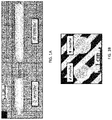
- FIG. 1A is a photograph of as-grown ingots of lithium chloride-cerium chloride (LiCl—CeCl 3 ) eutectics grown with a translation speed of 2 millimeter per hour (mm/hr) (left) or 8 mm/hr (right).
- the scale bar in the upper left represents 1 centimeter.
- FIG. 1B is a photograph of 7 ⁇ 1 cubic millimeter (mm 3 ) slabs of the ingots shown in FIG. 1A .
- the slabs were cut perpendicular to the ingot axis.
- the eutectic grown with a translation speed of 2 millimeter per hour (mm/hr) is on the left and that grown with a translation speed of 8 mm/hr on the right.
- the scale bar at the bottom represents 1 centimeter.
- FIG. 2A is a scanning electron microscope (SEM) image of a transaxial cross-section of a lithium chloride-cerium chloride (LiCl—CeCl 3 ) slab grown with a pulling rate of 2 millimeters per hour.
- the scale bar in the lower right represents 20 micrometers ( ⁇ m).
- FIG. 2B is an energy-dispersive spectroscopy (EDS) image of the sample shown in FIG. 2A .
- the scale bar in the lower right represents 20 micrometers ( ⁇ m).
- FIG. 2C is a scanning electron microscope (SEM) image of a transaxial cross-section of a lithium chloride-cerium chloride (LiCl—CeCl 3 ) slab grown with a pulling rate of 8 millimeters per hour.
- the scale bar in the lower right represents 20 micrometers ( ⁇ m).
- FIG. 2D is an energy-dispersive spectroscopy (EDS) image of the sample shown in FIG. 2C .
- the scale bar in the lower right represents 20 micrometers ( ⁇ m).
- FIG. 3A is a pair of graphs showing the photoluminescence (PL) emission and photoluminescence excitation (PLE) spectra (intensity in arbitrary units versus wavelength in nanometers (nm)) of lithium chloride-cerium chloride (LiCl—CeCl 3 ) eutectics grown with pulling rates of 2 millimeters per hour (mm/hr) (top) and 8 mm/hr (bottom).
- PL photoluminescence
- PLE photoluminescence excitation
- FIG. 3B is a pair of graphs showing the photoluminescence (PL) decay profiles (counts in arbitrary units versus time in nanoseconds (ns)) under 265 nanometer excitation of lithium chloride-cerium chloride (LiCl—CeCl 3 ) eutectics grown with pulling rates of 2 millimeters per hour (mm/hr) (top) and 8 mm/hr (bottom).
- PL photoluminescence
- FIG. 3C is a graph showing the X-ray excited radioluminescence (RL) spectra (intensity in arbitrary units versus wavelength in nanometers (nm)) of lithium chloride-cerium chloride (LiCl—CeCl 3 ) eutectics grown with pulling rates of 2 millimeters per hour (mm/hr) (solid line) and 8 mm/hr (dotted line).
- RL X-ray excited radioluminescence
- FIG. 3D is a graph showing the scintillation decay profiles (counts in arbitrary units versus time in nanoseconds (ns)) under cesium-137 ( 137 Cs) irradiation of lithium chloride-cerium chloride (LiCl—CeCl 3 ) eutectics grown with pulling rates of 2 millimeters per hour (mm/hr) (solid filled circles) and 8 mm/hr (circles filled with “+”s).
- FIG. 4A is a graph of the cadmium(Cd)-covered corrected spectrum (counts per channel versus channel number) collected for the lithium chloride-cerium chloride (LiCl—CeCl 3 ) eutectic scintillator grown with a pulling rate of 2 millimeters per hour under plutonium/beryllium (Pu/Be) neutron source irradiation. Filled circles show background. Unfilled circles show thermal neutron response.
- LiCl—CeCl 3 lithium chloride-cerium chloride
- FIG. 4B is a graph of the cadmium(Cd)-covered corrected spectrum (counts per channel versus channel number) collected for the lithium chloride-cerium chloride (LiCl—CeCl 3 ) eutectic scintillator grown with a pulling rate of 8 millimeters per hour under plutonium/beryllium (Pu/Be) neutron source irradiation. Filled circles show background. Unfilled circles show thermal neutron response.
- LiCl—CeCl 3 lithium chloride-cerium chloride
- FIG. 5 is a schematic drawing of an apparatus for detecting radiation according to an aspect of the presently disclosed subject matter.
- Apparatus 10 includes photon detector 12 optically coupled to scintillator material 14 .
- Apparatus 10 can optionally include electronics 16 for recording and/or displaying electronic signal from photon detector 12 .
- optional electronics 16 can be in electronic communication with photon detector 12 .
- LiCl—CeCl 3 (e.g., nat LiCl—CeCl 3 ) eutectic scintillators for thermal neutron detection were synthesized by using the vertical Bridgman method.
- An exemplary eutectic molar ratio of LiCl and CeCl 3 is about 0.75/0.25.
- the effect of solidification speed on the microstructure, optical properties, and scintillation properties under gamma ( ⁇ ) and neutron irradiation were studied.
- the grown exemplary LiCl—CeCl 3 eutectics have a lamellar structure.
- the scintillation decay time of exemplary LiCl—CeCl 3 eutectics under gamma ( ⁇ ) irradiation is about 20 ns.
- the energy spectra under Pu/Be source irradiation indicates that the synthesized LiCl—CeCl 3 is capable of detecting thermal neutron.
- the phrase “consisting of” excludes any element, step, or ingredient not specified.
- the phrase “consists of” appears in a clause of the body of a claim, rather than immediately following the preamble, it limits only the element set forth in that clause; other elements are not excluded from the claim as a whole.
- the term “about”, when referring to a value is meant to encompass variations of in one example ⁇ 20% or ⁇ 10%, in another example ⁇ 5%, in another example ⁇ 1%, and in still another example ⁇ 0.1% from the specified amount, as such variations are appropriate to perform the disclosed methods.
- sintillator refers to a material that emits light (e.g., visible light) in response to stimulation by high energy radiation (e.g., X, ⁇ , ⁇ , or ⁇ radiation).
- high energy radiation e.g., X, ⁇ , ⁇ , or ⁇ radiation.
- phosphor refers to a material that emits light (e.g., visible light) in response to irradiation with electromagnetic or particle radiation.
- optical material refers to material that are scintillators and/or phosphors.
- high energy radiation can refer to electromagnetic radiation having energy higher than that of ultraviolet radiation, including, but not limited to X radiation (i.e., X-ray radiation), alpha ( ⁇ ) particles, gamma ( ⁇ ) radiation, and beta ( ⁇ ) radiation.
- the high energy radiation refers to gamma rays, cosmic rays, X-rays, and/or particles (e.g., neutrons) having an energy of 1 keV or greater.
- Scintillator materials as described herein can be used as components of radiation detectors in apparatuses such as counters, image intensifiers, and computed tomography (CT) scanners.
- CT computed tomography
- Optical coupling refers to a physical coupling between a scintillator and a photosensor, e.g., via the presence of optical grease or another optical coupling compound (or index matching compound) that bridges the gap between the scintillator and the photosensor.
- optical coupling compounds can include, for example, liquids, oils and gels.
- Light output can refer to the number of light photons produced per unit energy deposited, e.g., by a gamma ray being absorbed, typically the number of light photons per megaelectronvolt (ph/MeV).
- chemical ions can be represented simply by their chemical element symbols alone (e.g., Li for lithium ion(s) (e.g., Li + ) or Ce for cerium ion(s) (e.g., Ce 3+ )).
- Eutectic materials are mixtures of two or more solid phases solidified simultaneously from melts corresponding to eutectic compositions.
- a solid phase of less molar ratio is normally surrounded by the matrix phase, and typical lamellar and cylindrical structures are formed with a periodic arrangement of two phases. These structures are both shaped because the as grown mixtures tend to minimize the interface between the co-existing phases.
- the correlation between microstructure and solidification speed provides an approach to design self-assembled eutectic materials with unique physical properties for structural and functional applications.
- 2 Eutectic materials can be synthesized from the melt by using the Czochralski, 3 the micro-pulling down, 4,5 and the Bridgman methods. 6-9
- Scintillation materials that can transform high-energy photons or particles into visible or ultraviolet lights have played an important role in the field of radiation detection, such as medical imaging, homeland security, high-energy physics, and industrial inspection.
- Self-assembled eutectics with tunable microstructures have recently been proposed as potential next-generation X-ray and neutron imaging materials.
- X-ray and neutron imaging materials can benefit from both high spatial resolution and high detection efficiency.
- halide and oxide eutectics with ordered microstructure such as CsI—NaCl:Tl + and GdAlO 3 —Al 2 O 3 :Ce 3+ , 3,5,10,11 developed for X-ray imaging have shown good optical guide performance due to the total reflection of luminescent light occurring in the fiber or matrix phase depending on their refractive indices.
- eutectic scintillators have been considered for neutron detection because of the deficit of 3 He gas, 12 a material often used in neutron detection.
- 6 Li-containing scintillators are promising alternatives to 3 He gas proportional counters due to the high Q-value of 4.8 MeV of 6 Li(n, ⁇ ) 3 H reaction, including Li-glass, 13 LiF/ZnS ceramics, 14 lithium indium diselenide, 15,16 Cs 2 LiYCl 6 :Ce 3+ , 17 LiCaAlF 6 :Eu 2+ , 18 and LiF:Eu 2+ crystals.
- LiCl—CeCl 3 eutectic scintillators such as 75% LiCl-25% CeCl 3 , 21 for the detection of thermal neutrons and potentially fast neutrons because of the presence of chlorine.
- the CeCl 3 phase acting as a spectral transformer, can emit scintillation light peaking at 365 nm under ionizing irradiation and achieve a high light yield of 28,000 photons/MeV. 22 Because the refractive index of CeCl 3 is 2.2 at 365 nm, 23 which is higher than that of LiCl 3 at 1.67, 24 most of the produced light can propagate in the CeCl 3 phase through total internal reflection.
- LiCl—CeCl 3 eutectics were grown by the Bridgman method. To understand the effects of solidification speed on the microstructure, optical and scintillation properties of LiCl—CeCl 3 eutectics, scanning electron microscopy, energy-dispersive spectroscopy, photoluminescence excitation and emission, X-ray induced radioluminescence, and Pu/Be induced pulse height spectra were used.
- the presently disclosed subject matter provides an optical material (i.e., a phosphor and/or scintillator) comprising a eutectic LiCl—CeCl 3 composition.
- an optical material i.e., a phosphor and/or scintillator
- the eutectic LiCl—CeCl 3 composition comprises about 75 mole % LiCl and about 25 mole % CeCl 3 .
- the eutectic LiCl—CeCl 3 composition comprises naturally enriched lithium ( nat Li), i.e., the composition comprises a naturally occurring ratio of lithium isotopes.
- the Li in the LiCl component of the eutectic composition has a naturally occurring distribution of lithium-6 ( 6 Li) and lithium-7 ( 7 Li) isotopes, i.e., where the Li in the LiCl comprises about 92.5% 7 Li.
- the eutectic composition comprises an isotopically enriched lithium, i.e., where the Li does not have a naturally occurring distribution of lithium isotopes.
- the isotopically enriched lithium is 6 Li, i.e., and the LiCl component comprises Li with a higher than naturally occurring ratio of 6 Li to 7 Li. The presence of 6 Li can enhance neutron detection.
- the eutectic LiCl—CeCl 3 composition can comprise two non-identical solid phases (a LiCl phase and a CeCl 3 phase) having a cylindrical or lamellar structure.
- the composition has a lamellar structure.
- the phase thicknesses and/or uniformity of the LiCl and CeCl 3 phases can be varied, in some embodiments, depending upon synthesis conditions, e.g., pulling rate during synthesis of the eutectic composition via the Bridgman technique. For example, a more rapid pulling rate can result in thinner and/or more phase thickness.
- the thickness and/or uniformity of the structure can affect light transport efficiency in the material.
- the phase thicknesses of the LiCl and CeCl 3 phases can be about 10 mm or less. In some embodiments the phase thicknesses can be about 1 mm to about 10 mm (e.g., about 1, 2, 3, 4, 5, 6, 7, 8, 9, or about 10 mm). In some embodiments, the phase thicknesses can be about 5 to about 10 mm.
- the eutectic LiCl—CeCl 3 composition is prepared by the Bridgman method.
- the pulling rate used during preparation of the composition is about 2 millimeters per hour (mm/hr) to about 8 mm/hr (e.g., about 2, 3, 4, 5, 6, 7, or about 8 mm/hr).
- the presently disclosed subject matter provides a radiation detector comprising a scintillator material comprising, consisting essentially of, or consisting of a eutectic LiCl—CeCl 3 composition.
- the radiation detector can comprise the scintillator material (which absorbs radiation and emits light) and a photodetector (which detects said emitted light).
- the photodetector can be any suitable detector or detectors and can be or not be optically coupled to the scintillator material for producing an electrical signal in response to emission of light from the scintillator material.
- the photodetector can be configured to convert photons to an electrical signal.
- a signal amplifier can be provided to convert an output signal from a photodiode into a voltage signal.
- the signal amplifier can also be designed to amplify the voltage signal.
- Electronics associated with the photodetector can be used to shape and digitize the electronic signal.
- the presently disclosed subject matter provides an apparatus 10 for detecting radiation wherein the apparatus comprises a photon detector 12 and a scintillator material 14 (e.g., a eutectic LiCl—CeCl 3 composition such as 75 mole % LiCl and 25 mole % CeCl 3 ).
- Scintillator material 14 can convert radiation to light that can be collected by a charge-coupled device (CCD) or a photomultiplier tube (PMT) or other photon detector 12 efficiently and at a fast rate.
- CCD charge-coupled device
- PMT photomultiplier tube
- photon detector 12 can be any suitable detector or detectors and can be optically coupled (e.g., via optical grease or another optical coupling compound, such as an optical coupling oil or liquid) to the scintillator (e.g., a eutectic LiCl—CeCl 3 scintillator material) for producing an electrical signal in response to emission of light from the scintillator.
- the scintillator e.g., a eutectic LiCl—CeCl 3 scintillator material
- photon detector 12 can be configured to convert photons to an electrical signal.
- Electronics associated with photon detector 12 can be used to shape and digitize the electronic signal.
- Suitable photon detectors 12 include, but are not limited to, photomultiplier tubes, photodiodes, CCD sensors, and image intensifiers.
- Apparatus 10 can also include electronics 16 for recording and/or displaying the electronic signal.
- the radiation detector is configured for use as part of a medical or veterinary diagnostic device, a device for oil or other geological exploration (e.g., oil well logging probes), a device or instrument for surveying or as a device for security and/or military-related purposes (e.g., as a device for container, vehicle, or baggage scanning or for scanning humans or other animals).
- the medical or veterinary diagnostic device is selected from, but not limited to, a positron emission tomography (PET) device, an X-ray computed tomography (CT) device, a single photon emission computed tomography (SPECT) device, or a planar nuclear medical imaging device.
- the radiation detector can be configured to move (e.g., via mechanical and/or electronic controls) over and/or around a sample, such as a human or animal subject, such that it can detect radiation emitted from any desired site or sites on the sample.
- the detector can be set or mounted on a rotating body to rotate the detector around a sample.
- the device can also include a radiation source.
- an X-ray CT device of the presently disclosed subject matter can include an X-ray source for radiating X-rays and a detector for detecting said X-rays.
- the device can comprise a plurality of radiation detectors. The plurality of radiation detectors can be arranged, for example, in a cylindrical or other desired shape, for detecting radiation emitted from various positions on the surface of a sample.
- the presently disclosed subject matter provides a method for detecting radiation (or the absence of radiation) using a radiation detector comprising a scintillator material comprising, consisting essentially of, or consisting of a eutectic LiCl—CeCl 3 composition as described hereinabove (e.g., a eutectic composition comprising about 75 mole % LiCl and about 25 mole % CeCl 3 ).
- the presently disclosed subject matter provides a method of detecting gamma rays, X-rays, cosmic rays and particles having an energy of 1 keV or greater, wherein the method comprises using a radiation detector comprising a scintillator material comprising, consisting essentially of, or consisting of a eutectic LiCl—CeCl 3 composition as described hereinabove (e.g., a eutectic composition comprising about 75 mole % LiCl and about 25 mole % CeCl 3 ).
- the scintillator material comprises nat Li.
- the scintillator material comprises an isotopically enriched Li, e.g, 6 Li. In some embodiments, the scintillator material comprises a lamellar structure, e.g., having phase thicknesses of about 10 mm or less (e.g., about 5 mm to about 10 mm).
- the presently disclosed subject matter provides a method for detecting neutrons (e.g., thermal neutrons) using a radiation detector comprising a scintillation material comprising, consisting essentially of, or consisting of a eutectic LiCl—CeCl 3 composition as described hereinabove (e.g., a eutectic composition comprising about 75 mole % LiCl and about 25 mole % CeCl 3 ).
- Radiation detectors that can detect neutrons can be used, for example, to measure power in nuclear or research reactors; as research instruments in the fields of materials science, plasma physics, and particle physics; and to detect cosmic rays and/or special nuclear materials.
- the radiation detector can be a medical diagnostic device, a device for oil exploration, a surveying device, or a device for container or baggage scanning.
- the radiation detector can be a scientific research device.
- the presently disclosed methods can comprise providing a radiation detector comprising a photodetector and a scintillator material comprising, consisting essentially of, or consisting of a eutectic composition of the presently disclosed subject matter; positioning the detector, wherein the positioning comprises placing the detector in a location wherein the scintillator material is in the path of a beam of radiation (or the suspected path of a beam of radiation); and detecting light (or detecting the absence of light) emitted by the scintillator material with the photodetector.
- Detecting the light emitted by the scintillator material can comprise converting photons to an electrical signal. Detecting can also comprise processing the electrical signal to shape, digitize, or amplify the signal.
- the method can further comprise displaying the electrical signal or processed electrical signal.
- the presently disclosed eutectic compositions can be prepared via any suitable method as would be apparent to one of ordinary skill in the art upon a review of the instant disclosure.
- the method comprises preparing a crystal (e.g., a single crystal) from a melt (i.e., a mixture of molten raw materials).
- the composition can be prepared by the Bridgman method (e.g., the vertical Bridgman or Bridgman-Stockbarger method), wherein a crucible or ampoule containing a melt of the molten raw materials is pulled through a temperature gradient in a furnace from a warmer region of the furnace to a cooler region, causing the molten raw materials to slowly cool and a crystal or crystals to form.
- Alternative methods for producing the presently disclosed compositions include, but are not limited to the micro-pulling down method, the Czochralski (pulling-up) method, zone melt method, Edge-defined Film-fed Growth (EFG) method, and hot isostatic press (HIP) sintering method.
- the raw materials (i.e., “starting materials”) for the composition comprise CeCl 3 and LiCl.
- the starting materials include 6 Li enriched LiCl.
- a high-purity raw material e.g., having a purity of 99.99% or higher and/or not containing more than 1 ppm of an impurity
- These starting materials can be weighed and mixed such that a desired composition is obtained at the time of forming a melt.
- the raw materials can be measured out and mixed, e.g., using a ball mill, etc., and the mixed powder heated to a temperature above the melting temperature of the raw material with the highest melting temperature (e.g., above the 817° C. melting temperature of CeCl 3 ) to provide a homogenous mixture of raw materials and cooled.
- a temperature above the melting temperature of the raw material with the highest melting temperature e.g., above the 817° C. melting temperature of CeCl 3
- the method further comprises annealing the scintillator material for a period of time (e.g., between a few hours and a few days).
- the annealing can be performed, for example, under vacuum, in nitrogen, or a mixture of nitrogen and hydrogen.
- the annealing can be done at any suitable temperature that is lower than the melting point of the material, e.g., between about 100 and about 450 degrees Celsius (e.g., about 100, 150, 200, 250, 300, 350, 400, or about 450 degrees Celsius).
- the annealing increases the light yield of the material and/or provides a material with a faster scintillation decay time.
- the annealing is performed under vacuum.
- the presently disclosed subject matter provides a method of preparing an optical material (i.e., a scintillator and/or phosphor) comprising, consisting essentially of, or consisting of a eutectic LiCl—CeCl 3 material.
- the method comprises: (a) providing a mixture of CeCl 3 and LiCl; (b) sealing the mixture in a sealed container (e.g., an ampoule or crucible); (c) heating the container in a furnace to a temperature where the mixture forms a melt (e.g., to approximately 820° C.-850° C.); and (d) slowly cooling the sealed container.
- mixture of step (a) comprises about 25 mole % CeCl 3 and about 75 mole % LiCl.
- sealing the mixture is dried for a period of time prior to step (b) or step (c), e.g., under elevated temperature or reduced pressure.
- slowly cooling the sealed container comprises pulling the sealed container through a furnace having a temperature gradient.
- the temperature gradient is about 40° C. per centimeter.
- the pulling is performed at a rate of about 2 millimeters per hour (mm/hr) to about 8 mm/hr (e.g., about 2, 3, 4, 5, 6, 7, or about 8 mm/hr).
- Anhydrous, high-purity beads of (99.99%) CeCl 3 and LiCl were used as starting materials.
- the compositions were mixed according to the stoichiometry of CeCl 3 —LiCl.
- the mixtures were then loaded into quartz ampoules.
- the ampoules were evacuated to 10 ⁇ 6 mbar and heated to 200° C. and kept there for 10 hours to remove residual water and oxygen impurities.
- After baking, the ampoules were sealed and transferred to a Bridgman growth furnace. They were passed through a temperature gradient of about 40° C./cm at a pulling rate of 2 mm/hr or 8 mm/hr. Finally, the furnace was cooled to room temperature at 20° C./hr. The diameter of the ingots was 7 mm.
- Photoluminescence emission (PL) and excitation (PLE) spectra were obtained with a Jobin Yvon Fluorolog-3 spectrofluorometer (Horiba, Kyoto, Japan).
- the excitation light went through an excitation monochromator with a 1 nm bandpass to ensure monochromaticity.
- the emission monochromator was set at a 1 nm bandpass to select emission light of a specific wavelength.
- a 450 W continuous xenon lamp was used as the excitation source.
- Photoluminescence decay was measured on the same spectrofluorometer using a time-correlated-single-photon counting module.
- Jobin Yvon NanoLEDs pulsed light-emitting diodes; Horiba, Kyoto, Japan
- the duration of the light pulse was shorter than 2 ns and therefore was not deconvoluted from the much longer decay profiles.
- the scintillation decay time was measured using a time-correlated single-photon counting setup under a 137 Cs gamma-ray source excitation.
- An X-ray tube operated at 35 kV and 0.1 mA was used as the excitation source for X-ray excited radioluminescence (RL) measurements.
- a Pu/Be neutron source located in the center of a 25 ⁇ 45 ⁇ 30 in 3 polyethylene moderator was used for thermal neutron response measurements. Each sample was coupled to a photomultiplier with optical grease. The PMT and scintillator were covered with tin foil and electrical tape to prevent light pollution.
- the pulse processing chain for the measurement consisted of a H6533 Hamamatsu photomultiplier tube (PMT) assembly (Hamamatsu Photonics K.
- the LiCl—CeCl 3 eutectics were grown with two different pulling rates of 2 and 8 mm/hr.
- the as-grown ingots are shown in FIG. 1A .
- the 1 mm thick slabs shown in FIG. 1B were cut perpendicular to the boule axis.
- the SEM images of the cross-sections of the LiCl—CeCl 3 slabs are shown in FIGS. 2A and 2C .
- Both eutectics show lamellar-like structure.
- the black and gray colored regions are associated with the LiCl and CeCl 3 phases, respectively.
- As the increase of pulling rate from 2 to 8 mm/hr the phase thickness of LiCl and CeCl 3 became smaller from roughly 10 to 5 mm.
- phase thickness can influence the ionizing energy deposition and detection spatial resolution.
- the variation of phase thickness with pulling rate fits the Hunt-Jackson law.
- the energy-dispersive spectroscopy (EDS) images show the distribution of Ce and Cl elements, shown in green and red, respectively, confirming the separation between CeCl 3 phases and LiCl phases.
- FIG. 3A Photoluminescence excitation and emission spectra of the LiCl—CeCl 3 eutectic samples are shown in FIG. 3A .
- the observed 340 and 365 nm emission peaks upon 265 nm excitation are ascribed to the Ce 3+ 5d-4f emissions. Under 310 nm excitation, the emission peaks are at the same wavelengths but with a lower intensity.
- two broad excitation bands peaking at 265 and 310 nm are observed.
- the decay time of the sample grown with a pulling rate of 2 mm/hr is 19.4 ns, slightly longer than the 17.7 ns decay time observed for the 8 mm/hr sample.
- the X-ray excited RL spectra are plotted in FIG. 3C .
- An intense emission peak appears at 365 nm in both samples related to Ce 3+ 5d-4f emission, consistent with the PL results.
- the emission peak was reported to be at 360 nm when excited with a 20 keV X-ray. 22
- the weak emission peak at 526 nm is believed to be related to defect emission, such as oxygen impurities.
- Scintillation decay profiles under 137 Cs irradiation are shown in FIG. 3D .
- the scintillation decay constant is 20.0 ns for the 2 mm/hr sample and 18.0 ns for the 8 mm/hr sample. The less than 1 ns difference between scintillation and PL decay constants suggests an efficient energy transfer from host to activators.
- FIGS. 4A and 4B present pulse height spectra of the LiCl—CeCl 3 eutectic scintillators recorded under a Pu/Be source irradiation. A thermal neutron response above background was observed in both samples.
- SRIM Stopping and Range of Ions in Matter
- a new LiCl—CeCl 3 eutectic was successfully prepared by the Bridgman method for thermal neutron detection application for the first time.
- the LiCl and CeCl 3 phases were well separated in the as-synthesized eutectics with a lamellar structure. With the increase of the pulling rate from 2 to 8 mm/hr, the phase thickness decreased from about 10 to 5 ⁇ m.
- the scintillation emission peak at 365 nm originated from Ce 3+ of 5d-4f de-excitation under X-ray irradiation. There is an efficient energy transfer from CeCl 3 host lattice to Ce 3+ centers.
Landscapes
- Chemical & Material Sciences (AREA)
- Spectroscopy & Molecular Physics (AREA)
- Physics & Mathematics (AREA)
- Crystallography & Structural Chemistry (AREA)
- Organic Chemistry (AREA)
- Materials Engineering (AREA)
- Engineering & Computer Science (AREA)
- Health & Medical Sciences (AREA)
- Life Sciences & Earth Sciences (AREA)
- General Physics & Mathematics (AREA)
- High Energy & Nuclear Physics (AREA)
- Molecular Biology (AREA)
- Inorganic Chemistry (AREA)
- Metallurgy (AREA)
- Luminescent Compositions (AREA)
- Measurement Of Radiation (AREA)
Abstract
Description
-
- °=degree
- ° C.=degrees Celsius
- %=percentage
- γ=gamma
- λem=emission wavelength
- λex=excitation wavelength
- μm=micrometer
- 6Li=lithium-6
- Ce=cerium
- Cl=chloride
- cm=centimeter
- EDS=energy-dispersive spectroscopy
- eV=electronvolt
- hr=hour
- in=inch
- keV=kiloelectronvolt
- kV=kilovolt
- natLi=naturally enriched lithium
- mA=milliampere
- MCA=multi-channel amplifier
- MeV=megaelectronvolt
- mm=millimeter
- mol=mole
- nm=nanometers
- ns=nanoseconds
- ph=photon
- PL=photoluminescence
- PLE=photoluminescence excitation
- PMT=photomultiplier tube
- RL=radioluminescence
- SEM=scanning electron microscopy
- W=watt
- 1. K. A. Jackson and J. D. Hunt, Trans. Metall. Soc. AIME, 1966, 236, 1129-1142.
- 2. A. Yoshikawa, K. Kamada, S. Kurosawa, Y. Yokota, A. Yamaji, V. I. Chani, Y. Ohashi and M. Yoshino, J. Cryst. Growth, 2018, 498, 170-178.
- 3. N. Yasui, T. Kobayashi, Y. Ohashi and T. Den, J. Cryst. Growth, 2014, 399, 7-12.
- 4. K. Nishimoto, Y. Yokota, S. Kurosawa, Y. Fujimoto, N. Kawaguchi, K. Fukuda and A. Yoshikawa, J. Eur. Ceram. Soc., 2014, 34, 2117-2121.
- 5. Y. Ohashi, N. Yasui, Y. Yokota, A. Yoshikawa and T. Den, Appl. Phys. Lett., 2013, 102.
- 6. N. Kawaguchi, K. Fukuda, T. Yanagida, Y. Fujimoto, Y. Yokota, T. Suyama, K. Watanabe, A. Yamazaki and A. Yoshikawa, Nucl. Instrum. Methods Phys. Res., Sect. A, 2011, 652, 209-211.
- 7. T. Yanagida, K. Fukuda, Y. Fujimoto, N. Kawaguchi, S. Kurosawa, A. Yamazaki, K. Watanabe, Y. Futami, Y. Yokota, J. Pejchal, A. Yoshikawa, A. Uritani and T. Iguchi, Opt. Mater., 2012, 34, 868-871.
- 8. T. Yanagida, Y. Fujimoto, K. Fukuda, N. Kawaguchi, K. Watanabe, A. Yamazaki, A. Uritani and V. Chani, Opt. Mater., 2013, 35, 1449-1454.
- 9. T. Yanagida, N. Kawaguchi, Y. Fujimoto, K. Fukuda, K. Watanabe, A. Yamazaki and A. Uritani, J. Lumin., 2013, 144, 212-216.
- 10. N. Yasui, Y. Ohashi, T. Kobayashi and T. Den, Adv. Mater., 2012, 24, 5464-5469.
- 11. T. Den, T. Saito, R. Horie, Y. Ohashi and N. Yasui, IEEE Trans. Nucl. Sci., 2013, 60, 16-19.
- 12. R. C. Runkle, A. Bernstein and P. E. Vanier, J. Appl. Phys., 2010, 108, 111101.
- 13. C. W. E. Van Eijk, IEEE Trans. Nucl. Sci., 2012, 59, 2242-2247.
- 14. H. likura, N. Tsutsui, T. Nakamura, M. Katagiri, M. Kureta, J. Kubo and M. Matsubayashi, Nucl. Instrum. Methods Phys. Res., Sect. A, 2011, 651, 100-104.
- 15. E. Lukosi, E. Herrera, D. Hamm, K.-M. Lee, B. Wiggins, P. Trtik, D. Penumadu, S. Young, L. Santodonato, H. Bilheux, A. Burger, L. Matei and A. C. Stowe, Nucl. Instrum. Methods Phys. Res., Sct. A, 2016, 830, 140-149.
- 16. B. Wiggins, M. Groza, E. Tupitsyn, E. Lukosi, K. Stassun, A. Burger and A. Stowe, Nucl. Instrum. Methods Phys. Res., Sect. A, 2015, 801, 73-77.
- 17. C. M. Combes, P. Dorenbos, C. W. E. van Eijk, K. W. Kramer and H. U. Gudel, J. Lumin., 1999, 82, 299-305.
- 18. D. Totsuka, T. Yanagida, K. Fukuda, N. Kawaguchi, Y. Fujimoto, J. Pejchal, Y. Yokota and A. Yoshikawa, Nucl. Instrum. Methods Phys. Res., Sect. A, 2011, 659, 399-402.
- 19. H. Yang, N. Menaa, F. Bronson, M. Kastner, R. Venkataraman and W. F. Mueller, Nucl. Instrum. Methods Phys. Res., Sect. A, 2011, 652, 364-369.
- 20. Y. Wu, E. D. Lukosi, M. Zhuravleva, A. C. Lindsey and C. L. Melcher, Nucl. Instrum. Methods Phys. Res., Sect. A, 2015, 797, 319-323.
- 21. C. Liang, Z. Chaogui, Y. Yupu, J. Chin. Rare Earth Soc. (China) 1990, 8, 92-93.
- 22. S. E. Derenzo, W. W. Moses, J. L. Cahoon, T. A. DeVol and L. Boatner, present in part at the Conference Record of the 1991 IEEE Nuclear Science Symposium and Medical Imaging Conference, Santa Fe, N. Mex., USA, Nov. 2-9, 1991.
- 23. C. Li, B. Wang, R. Wang and H. Wang, Solid State Commun., 2007, 144, 220-224.
- 24. H. H. Li, J. Phys. Chem. Ref. Data, 1976, 5, 329-528.
- 25. J. F. Ziegler, M. D. Ziegler and J. P. Biersack, Nucl. Instrum. Methods Phys. Res., Sect. B, 2010, 268, 1818-1823.
- 26. F. Cappella, A. d'Angelo and F. Montecchia, Nucl. Instrum. Methods Phys. Res., Sect. A, 2010, 618, 168-175.
- 27. M. B. Smith, T. Achtzehn, H. R. Andrews, E. T. H. Clifford, P. Forget, J. Glodo, R. Hawrami, H. Ing, P. O'Dougherty, K. S. Shah, U. Shirwadkar, L. Soundara-Pandian and J. Tower, Nucl. Instrum. Methods Phys. Res., Sect. A, 2015, 784, 162-167.
Claims (17)
Priority Applications (1)
| Application Number | Priority Date | Filing Date | Title |
|---|---|---|---|
| US17/187,412 US11474264B2 (en) | 2020-02-27 | 2021-02-26 | Self-assembled directionally solidified eutectics for thermal neutron detection |
Applications Claiming Priority (2)
| Application Number | Priority Date | Filing Date | Title |
|---|---|---|---|
| US202062982532P | 2020-02-27 | 2020-02-27 | |
| US17/187,412 US11474264B2 (en) | 2020-02-27 | 2021-02-26 | Self-assembled directionally solidified eutectics for thermal neutron detection |
Publications (2)
| Publication Number | Publication Date |
|---|---|
| US20210270980A1 US20210270980A1 (en) | 2021-09-02 |
| US11474264B2 true US11474264B2 (en) | 2022-10-18 |
Family
ID=77464139
Family Applications (1)
| Application Number | Title | Priority Date | Filing Date |
|---|---|---|---|
| US17/187,412 Active US11474264B2 (en) | 2020-02-27 | 2021-02-26 | Self-assembled directionally solidified eutectics for thermal neutron detection |
Country Status (1)
| Country | Link |
|---|---|
| US (1) | US11474264B2 (en) |
Families Citing this family (2)
| Publication number | Priority date | Publication date | Assignee | Title |
|---|---|---|---|---|
| US11560515B2 (en) | 2019-04-05 | 2023-01-24 | University Of Tennessee Research Foundation | Lutetium based oxyorthosilicate scintillators codoped with transition metals |
| US11339326B2 (en) | 2020-01-24 | 2022-05-24 | University Of Tennessee Research Foundation | Tl+-based and mixed halide A3B2X9-type scintillators |
Citations (4)
| Publication number | Priority date | Publication date | Assignee | Title |
|---|---|---|---|---|
| US9417343B1 (en) * | 2014-06-03 | 2016-08-16 | Radiation Monitoring Devices, Inc. | Neutron detector and fabrication method thereof |
| US20160280992A1 (en) * | 2014-10-21 | 2016-09-29 | Osaka Prefecture University Public Corporation | Method for manufacturing alkali halide-based scintillator powder and method for manufacturing scintillator material |
| US20170052265A1 (en) * | 2014-06-09 | 2017-02-23 | Tokuyama Corporation | Neutron scintillator and neutron detector |
| US20180066185A1 (en) * | 2016-09-06 | 2018-03-08 | Ut-Battelle, Llc | Divalent-Ion-Doped Single Crystal Alkali Halide Scintillators |
-
2021
- 2021-02-26 US US17/187,412 patent/US11474264B2/en active Active
Patent Citations (4)
| Publication number | Priority date | Publication date | Assignee | Title |
|---|---|---|---|---|
| US9417343B1 (en) * | 2014-06-03 | 2016-08-16 | Radiation Monitoring Devices, Inc. | Neutron detector and fabrication method thereof |
| US20170052265A1 (en) * | 2014-06-09 | 2017-02-23 | Tokuyama Corporation | Neutron scintillator and neutron detector |
| US20160280992A1 (en) * | 2014-10-21 | 2016-09-29 | Osaka Prefecture University Public Corporation | Method for manufacturing alkali halide-based scintillator powder and method for manufacturing scintillator material |
| US20180066185A1 (en) * | 2016-09-06 | 2018-03-08 | Ut-Battelle, Llc | Divalent-Ion-Doped Single Crystal Alkali Halide Scintillators |
Non-Patent Citations (28)
| Title |
|---|
| Cappella et al., "Performances and potential of a CeCl3 scintillator," Nucl. Instrum. Methods Phys. Res., Sect. A, vol. 618, pp. 168-175 (2010). |
| Cheng et al., "Self-assembled natLiCl-CeCl3 directionally solidified eutectics for thermal neutron detection," Cryst Eng Comm vol. 22, pp. 3269-3273 (2020). |
| Combes et al., "Optical and scintillation properties of pure and Ce3+-doped Cs2LiYCl6 and U3YCl6 : Ce3+ crystals," J. Lumin., vol. 82, pp. 299-305 (1999). |
| Den et al., "Phase-Separated Csl-NaCl Scintillator With Optical Guiding Function," IEEE Trans. Nucl. Sci., vol. 60, pp. 16-19 (2013). |
| Derenzo et al., "X-ray fluorescence measurements of 412 inorganic compounds", presented in part at the Conference Record of the 1991 IEEE Nuclear Science Symposium and Medical Imaging Conference, Santa Fe, NM, USA, Nov. 2-9, 1991. |
| Iikura et al., "Evaluations of the new LiF-scintillator and optional brightness enhancement films for neutron imaging", Nucl. Instrum. Methods Phys. Res., Sect. A, vol. 651, pp. 100-104 (2011). |
| Jackson et al., "Lamellar and Rod Eutectic Growth" Trans. Metall. Soc. AIME, vol. 236, pp. 1129-1142 (1966). |
| Kawaguchi et al., "Fabrication and characterization of large size 6LiF/CaF2:Eu eutectic composites with the ordered lamellar structure," Nucl. Instrum. Methods Phys. Res., Sect. A, vol. 652, pp. 209-211 (2011). |
| Li et al., "First-principles studies on the electronic and optical properties ofCeCl3and CeBr3," Solid State Commun., vol. 144, pp. 220-224 (2007). |
| Li, "Refractive index of alkali halides and its wavelength and temperature derivatives," J. Phys. Chem. Ref. Data, vol. 5, pp. 329-528 (1976). |
| Liang et al., Rare Earth Soc. (China) vol. 8, pp. 92-93 (1990). |
| Lukosi et al., "Lithium indium diselenide: A new scintillator for neutron imaging," Nucl. Instrum. Methods Phys. Res., Set. A, vol. 830, pp. 140-149 (2016). |
| Nishimoto et al., "Crystal growth of LiF/LiYF4 eutectic crystals and their luminescent properties," J. Eur. Ceram. Soc., vol. 34, pp. 2117-2121 (2014). |
| Ohashi et al., "Submicron-diameter phase-separated scintillator fibers for high-resolution X-ray imaging," Appl. Phys. Lett., vol. 102, Article ID 051907 (2013). |
| Runkle et al., "Securing special nuclear material: Recent advances I neutron detection and their role in nonproliferation", J. Appl. Phys., vol. 108, Article ID 111101 (2010). |
| Smith et al., "Fast neutron measurements using Cs2LiYCl6:Ce (CLYC) scintillator," Nucl. Instrum. Methods Phys. Res., Sect. A, vol. 784, pp. 162-167 (2015). |
| Totsuka et al., "Nuclear Instruments and Methods in Physics Research Section A: Accelerators, Spectrometers, Detectors and Associated Equipment," Nucl. Instrum. Methods Phys. Res., Sect. A, vol. 659, pp. 399-402 (2011). |
| Van Eijk, "Inorganic Scintillators for Thermal Neutron Detection," IEEE Trans. Nucl. Sci., vol. 59, pp. 2242-2247 (2012). |
| Wiggins et al., "Scintillation propertiesofsemiconducting 6LiInSe2 crystals toionizingradiation," Nucl. Instrum. Methods Phys. Res., Sect. A, vol. 801, pp. 73-77 (2015). |
| Wu et al., "A novel LiCl—BaCl2:Eu2+ eutectic scintillator for thermal neutron detection," Nucl. Instrum. Methods Phys. Res., Sect. A, vol. 797, pp. 319-323 (2015). |
| Yanagida et al., "Ce-doped LiF—SrF2 eutectic scintillators for thermal neutron detection produced at different solidification rates," Opt. Mater., vol. 35, pp. 1449-1454 (2013). |
| Yanagida et al., "Eu-doped 6LiF—SrF2 eutectic scintillators for neutron detection," Opt. Mater., vol. 34, pp. 868-871 (2012). |
| Yanagida et al., "Scintillation properties of LiF—SrF2 and LiF—CaF2 eutectic," J. Lumin., vol. 144, pp. 212-216 (2013). |
| Yang et al., "Evaluation of a Lil(Eu) neutron detector with coincident double photodiode readout," Nucl. Instrum. Methods Phys. Res., Sect. A, vol. 652, pp. 364-369 (2011). |
| Yasui et al., "Development of Phase-Separated Scintillators with Light-Guiding Properties," Adv. Mater., vol. 24, pp. 5464-5469 (2012). |
| Yasui et al., "Phase-separated Csl—NaCl scintillator grownby the Czochralski method," J. Cryst. Growth, vol. 399, pp. 7-12 (2014). |
| Yoshikawa et al., "Growth and characterization of directionally solidified eutectic systems for scintillator applications," J. Cryst. Growth, vol. 498, pp. 170-178 (2018). |
| Ziegler et al., "SRIM—The stopping and range of ions in matter (2010)," Nucl. Instrum. Methods Phys. Res., Sect. B, vol. 268, pp. 1818-1823 (2010). |
Also Published As
| Publication number | Publication date |
|---|---|
| US20210270980A1 (en) | 2021-09-02 |
Similar Documents
| Publication | Publication Date | Title |
|---|---|---|
| CN104508192B (en) | Multi-doped lutetium-based oxyorthosilicate scintillators with improved optical properties | |
| EP2386618B1 (en) | Halide scintillator for radiation detection | |
| USRE45930E1 (en) | Lanthanide doped strontium barium mixed halide scintillators | |
| Rutstrom et al. | Improved light yield and growth of large-volume ultrafast single crystal scintillators Cs2ZnCl4 and Cs3ZnCl5 | |
| Yanagida et al. | Eu-doped 6LiF–SrF2 eutectic scintillators for neutron detection | |
| US8598530B2 (en) | Chloride scintillator for radiation detection | |
| JP2018503706A (en) | Novel thallium-doped sodium iodide, cesium iodide or lithium iodide scintillator | |
| US10838083B2 (en) | Alkali and alkaline earth halides and methods thereof | |
| JP2008101180A (en) | Scintillator crystal and radiation detector | |
| US9404036B2 (en) | Alkali metal and alkali earth metal gadolinium halide scintillators | |
| Yanagida et al. | Ce-doped LiF–SrF2 eutectic scintillators for thermal neutron detection produced at different solidification rates | |
| Fujimoto et al. | Photoluminescence and Scintillation Properties of Rb 2 CeCl 5 Crystal. | |
| US11474264B2 (en) | Self-assembled directionally solidified eutectics for thermal neutron detection | |
| US11339326B2 (en) | Tl+-based and mixed halide A3B2X9-type scintillators | |
| Tariwong et al. | Crystal growth and scintillation properties of Tm3+ doped LaCl3 single crystal for radiation detection | |
| Cheng et al. | Self-assembled nat LiCl–CeCl 3 directionally solidified eutectics for thermal neutron detection | |
| Miah et al. | Advances in perovskite-based scintillation materials for gamma-ray spectroscopy: issues and opportunities | |
| Wu et al. | A novel LiCl–BaCl2: Eu2+ eutectic scintillator for thermal neutron detection | |
| KR101641946B1 (en) | Scintillator and method for manufacturing the same | |
| KR101276732B1 (en) | Radiation Sensor Scintillator, and Method of Fabricating and Applying the Same | |
| Sasaki et al. | Growth and Scintillation Properties of 6 Li Containing Ce: LaCl 3-Based Eutectic Scintillator for Neutron Detection | |
| KR20110111646A (en) | Scintillator for Radiation Sensor, and Manufacturing and Application Method Thereof | |
| Kawaguchi et al. | Inorganic Fluoride Scintillators | |
| Takizawa et al. | Growth of Eu doped LiBr/BaBr2 eutectic and its thermal neutron response | |
| US20240117246A1 (en) | A3bx5, a2bx4, abx3, and ax halide scintillators doped with transition metal ions |
Legal Events
| Date | Code | Title | Description |
|---|---|---|---|
| FEPP | Fee payment procedure |
Free format text: ENTITY STATUS SET TO UNDISCOUNTED (ORIGINAL EVENT CODE: BIG.); ENTITY STATUS OF PATENT OWNER: LARGE ENTITY |
|
| FEPP | Fee payment procedure |
Free format text: PETITION RELATED TO MAINTENANCE FEES GRANTED (ORIGINAL EVENT CODE: PTGR); ENTITY STATUS OF PATENT OWNER: LARGE ENTITY |
|
| AS | Assignment |
Owner name: UNIVERSITY OF TENNESSEE RESEARCH FOUNDATION, TENNESSEE Free format text: ASSIGNMENT OF ASSIGNORS INTEREST;ASSIGNORS:MELCHER, CHARLES L.;WU, YUNTAO;ZHURAVLEVA, MARIYA;SIGNING DATES FROM 20210325 TO 20210425;REEL/FRAME:056809/0667 |
|
| STPP | Information on status: patent application and granting procedure in general |
Free format text: DOCKETED NEW CASE - READY FOR EXAMINATION |
|
| STPP | Information on status: patent application and granting procedure in general |
Free format text: NOTICE OF ALLOWANCE MAILED -- APPLICATION RECEIVED IN OFFICE OF PUBLICATIONS |
|
| STPP | Information on status: patent application and granting procedure in general |
Free format text: PUBLICATIONS -- ISSUE FEE PAYMENT RECEIVED |
|
| STPP | Information on status: patent application and granting procedure in general |
Free format text: PUBLICATIONS -- ISSUE FEE PAYMENT VERIFIED |
|
| STCF | Information on status: patent grant |
Free format text: PATENTED CASE |
|
| MAFP | Maintenance fee payment |
Free format text: PAYMENT OF MAINTENANCE FEE, 4TH YEAR, LARGE ENTITY (ORIGINAL EVENT CODE: M1551); ENTITY STATUS OF PATENT OWNER: LARGE ENTITY Year of fee payment: 4 |