US11470617B2 - Method and apparatus for indicating information, base station, and user equipment - Google Patents
Method and apparatus for indicating information, base station, and user equipment Download PDFInfo
- Publication number
- US11470617B2 US11470617B2 US16/870,919 US202016870919A US11470617B2 US 11470617 B2 US11470617 B2 US 11470617B2 US 202016870919 A US202016870919 A US 202016870919A US 11470617 B2 US11470617 B2 US 11470617B2
- Authority
- US
- United States
- Prior art keywords
- ssb
- rmsi
- coreset
- time
- indication information
- Prior art date
- Legal status (The legal status is an assumption and is not a legal conclusion. Google has not performed a legal analysis and makes no representation as to the accuracy of the status listed.)
- Active, expires
Links
- 238000000034 method Methods 0.000 title claims abstract description 46
- 238000012545 processing Methods 0.000 claims description 22
- 230000011664 signaling Effects 0.000 claims description 14
- 238000010586 diagram Methods 0.000 description 20
- 238000004891 communication Methods 0.000 description 14
- 238000004590 computer program Methods 0.000 description 10
- 230000003287 optical effect Effects 0.000 description 8
- 230000009471 action Effects 0.000 description 5
- 238000005516 engineering process Methods 0.000 description 5
- 230000003993 interaction Effects 0.000 description 4
- 238000007726 management method Methods 0.000 description 4
- 230000005236 sound signal Effects 0.000 description 4
- 101150071746 Pbsn gene Proteins 0.000 description 3
- 238000013500 data storage Methods 0.000 description 3
- 230000008569 process Effects 0.000 description 3
- 230000000644 propagated effect Effects 0.000 description 3
- 230000001133 acceleration Effects 0.000 description 2
- 230000008859 change Effects 0.000 description 2
- 239000004973 liquid crystal related substance Substances 0.000 description 2
- 239000000463 material Substances 0.000 description 2
- 238000012986 modification Methods 0.000 description 2
- 230000004048 modification Effects 0.000 description 2
- 230000002093 peripheral effect Effects 0.000 description 2
- 238000013515 script Methods 0.000 description 2
- 239000004065 semiconductor Substances 0.000 description 2
- 238000000926 separation method Methods 0.000 description 2
- 235000019527 sweetened beverage Nutrition 0.000 description 2
- 101710141937 Single-stranded DNA-binding protein 3 Proteins 0.000 description 1
- 230000006978 adaptation Effects 0.000 description 1
- 238000003491 array Methods 0.000 description 1
- 230000008901 benefit Effects 0.000 description 1
- 230000005540 biological transmission Effects 0.000 description 1
- 230000000295 complement effect Effects 0.000 description 1
- 239000011521 glass Substances 0.000 description 1
- 238000003384 imaging method Methods 0.000 description 1
- 229910044991 metal oxide Inorganic materials 0.000 description 1
- 150000004706 metal oxides Chemical class 0.000 description 1
- 239000000758 substrate Substances 0.000 description 1
- 238000012546 transfer Methods 0.000 description 1
Images


Classifications
-
- H04W72/0493—
-
- H—ELECTRICITY
- H04—ELECTRIC COMMUNICATION TECHNIQUE
- H04L—TRANSMISSION OF DIGITAL INFORMATION, e.g. TELEGRAPHIC COMMUNICATION
- H04L5/00—Arrangements affording multiple use of the transmission path
- H04L5/0001—Arrangements for dividing the transmission path
- H04L5/0003—Two-dimensional division
- H04L5/0005—Time-frequency
- H04L5/0007—Time-frequency the frequencies being orthogonal, e.g. OFDM(A) or DMT
-
- H—ELECTRICITY
- H04—ELECTRIC COMMUNICATION TECHNIQUE
- H04W—WIRELESS COMMUNICATION NETWORKS
- H04W72/00—Local resource management
- H04W72/50—Allocation or scheduling criteria for wireless resources
- H04W72/53—Allocation or scheduling criteria for wireless resources based on regulatory allocation policies
-
- H—ELECTRICITY
- H04—ELECTRIC COMMUNICATION TECHNIQUE
- H04L—TRANSMISSION OF DIGITAL INFORMATION, e.g. TELEGRAPHIC COMMUNICATION
- H04L5/00—Arrangements affording multiple use of the transmission path
- H04L5/003—Arrangements for allocating sub-channels of the transmission path
- H04L5/0048—Allocation of pilot signals, i.e. of signals known to the receiver
-
- H—ELECTRICITY
- H04—ELECTRIC COMMUNICATION TECHNIQUE
- H04L—TRANSMISSION OF DIGITAL INFORMATION, e.g. TELEGRAPHIC COMMUNICATION
- H04L5/00—Arrangements affording multiple use of the transmission path
- H04L5/003—Arrangements for allocating sub-channels of the transmission path
- H04L5/0053—Allocation of signalling, i.e. of overhead other than pilot signals
-
- H—ELECTRICITY
- H04—ELECTRIC COMMUNICATION TECHNIQUE
- H04L—TRANSMISSION OF DIGITAL INFORMATION, e.g. TELEGRAPHIC COMMUNICATION
- H04L5/00—Arrangements affording multiple use of the transmission path
- H04L5/003—Arrangements for allocating sub-channels of the transmission path
- H04L5/0078—Timing of allocation
-
- H—ELECTRICITY
- H04—ELECTRIC COMMUNICATION TECHNIQUE
- H04L—TRANSMISSION OF DIGITAL INFORMATION, e.g. TELEGRAPHIC COMMUNICATION
- H04L5/00—Arrangements affording multiple use of the transmission path
- H04L5/0091—Signalling for the administration of the divided path, e.g. signalling of configuration information
- H04L5/0094—Indication of how sub-channels of the path are allocated
-
- H—ELECTRICITY
- H04—ELECTRIC COMMUNICATION TECHNIQUE
- H04W—WIRELESS COMMUNICATION NETWORKS
- H04W56/00—Synchronisation arrangements
-
- H—ELECTRICITY
- H04—ELECTRIC COMMUNICATION TECHNIQUE
- H04W—WIRELESS COMMUNICATION NETWORKS
- H04W56/00—Synchronisation arrangements
- H04W56/001—Synchronization between nodes
-
- H—ELECTRICITY
- H04—ELECTRIC COMMUNICATION TECHNIQUE
- H04W—WIRELESS COMMUNICATION NETWORKS
- H04W56/00—Synchronisation arrangements
- H04W56/001—Synchronization between nodes
- H04W56/0015—Synchronization between nodes one node acting as a reference for the others
-
- H04W72/005—
-
- H—ELECTRICITY
- H04—ELECTRIC COMMUNICATION TECHNIQUE
- H04W—WIRELESS COMMUNICATION NETWORKS
- H04W72/00—Local resource management
- H04W72/30—Resource management for broadcast services
Definitions
- the information of the CORESET for the RMSI includes information of a frequency domain, a time domain, a Physical Downlink Control Channel (PDCCH) search window, a cycle and the like.
- a length for indication information of a CORESET for RMSI in a PBCH is about 8 bits, and 1 bit is configured to represent two probable Subcarrier Spacings (SCSs) of the RMSI.
- the present disclosure generally relates to the technical field of communication, and more specifically to a method and device for information indication, a method and device for searching a common Core Resource Set (CORESET) for Remaining Minimum System Information (RMSI), a base station, User Equipment (UE) and a computer-readable storage medium.
- CORESET Core Resource Set
- RMSI Remaining Minimum System Information
- UE User Equipment
- a method for information indication which may be applied to a base station and include that:
- the time-frequency multiplexing indication information indicates TDM of the CORESET for the RMSI and the SSB, an offset value between the PRB grid of the CORESET for the RMSI and the PRB grid of the SSB is indicated through the time-frequency multiplexing indication information;
- the SSB carrying the time-frequency multiplexing indication information is sent to UE in a beam scanning manner.
- a method for searching a common CORESET for RMSI which may be applied to UE and include that:
- an SSB carrying time-frequency multiplexing indication information of the CORESET for RMSI is received from a base station, the time-frequency multiplexing indication information being in a PBCH of the SSB;
- an SCS of the SSB is determined, and the PBCH of the SSB is parsed to obtain an SCS and the time-frequency multiplexing indication information of the CORESET for the RMSI;
- an offset value between the PRB grid of the CORESET for the RMSI and the PRB grid of the SSB is acquired from the time-frequency multiplexing indication information, and the CORESET for the RMSI is searched in a corresponding frequency domain according to the offset value between the PRB grid of the CORESET for the RMSI and the PRB grid of the SSB.
- a device for searching a common CORESET for RMSI which may be applied to UE and include:
- processors and memory configured to store processor-executable instructions, herein the processor is configured to:
- time-frequency multiplexing indication information of a CORESET for RMSI from a base station, the time-frequency multiplexing indication information being in a PBCH of the SSB;
- the time-frequency multiplexing indication information indicates the TDM of the CORESET for the RMSI and the SSB, acquire a offset value between the PRB grid of the CORESET for the RMSI and the PRB grid of the SSB from the time-frequency multiplexing indication information and search the CORESET for the RMSI in a corresponding frequency domain according to the offset value between the PRB grid of the CORESET for the RMSI and the PRB grid of the SSB.
- FIG. 1 is a flowchart showing a method for information indication, according to some embodiments of the present disclosure.
- FIG. 2A is a first schematic diagram illustrating TDM of a CORESET for RMSI and an SSB, according to some embodiments of the present disclosure.
- FIG. 2B is a second schematic diagram illustrating TDM of a CORESET for RMSI and an SSB, according to some embodiments of the present disclosure.
- FIG. 3 is a flowchart showing another method for information indication, according to some embodiments of the present disclosure.
- FIG. 4 is a flowchart showing another method for information indication, according to some embodiments of the present disclosure.
- FIG. 5 is a flowchart showing a method for searching a CORESET for RMSI, according to some embodiments of the present disclosure.
- FIG. 6 is a flowchart showing another method for searching a CORESET for RMSI, according to some embodiments of the present disclosure.
- FIG. 7 is a flowchart showing another method for searching a CORESET for RMSI, according to some embodiments of the present disclosure.
- FIG. 8 is a block diagram of a device for information indication, according to some embodiments.
- FIG. 9A is a block diagram of another device for information indication, according to some embodiments of the present disclosure.
- FIG. 9B is a block diagram of another device for information indication, according to some embodiments of the present disclosure.
- FIG. 10 is a block diagram of a device for searching a CORESET for RMSI, according to some embodiments of the present disclosure.
- FIG. 11A is a block diagram of another device for searching a CORESET for RMSI, according to some embodiments of the present disclosure.
- FIG. 11B is a block diagram of another device for searching a CORESET for RMSI, according to some embodiments of the present disclosure.
- FIG. 11C is a block diagram of another device for searching a CORESET for RMSI, according to some embodiments of the present disclosure.
- FIG. 12 is a block diagram of a device for searching a CORESET for RMSI, according to some embodiments of the present disclosure.
- FIG. 13 is a block diagram of a device for information indication, according to some embodiments of the present disclosure.
- Physical Resource Block (PRB) grids of a CORESET for RMSI are distributed with reference to PRB grids of a Synchronization Signal Block (SSB).
- SSB Synchronization Signal Block
- Various embodiments of the present disclosure provide a method and device for information indication, a method and device for searching a CORESET for RMSI, a base station, UE and a computer-readable storage medium, to indicate an offset between a PRB grid of a CORESET for RMSI and a PRB grid of an SSB by use of time-frequency multiplexing indication information of the CORESET for the RMSI, thereby achieving the purpose of reducing a bit overhead.
- FIG. 1 is a flowchart showing a method for information indication, according to some embodiments of the present disclosure. The embodiment is described from a base station side. As shown in FIG. 1 , the method for information indication includes the following blocks.
- the time-frequency multiplexing indication information of the CORESET for the RMSI is in the PBCH of the corresponding SSB, and the time-frequency multiplexing indication information is used to indicate TDM or FDM of the CORESET for the RMSI and the SSB.
- the time-frequency multiplexing indication information of the CORESET for the RMSI may be shown in Table 1.
- FDM is implemented for the CORESET for the RMSI and the SSB, and the frequency band where the CORESET for the RMSI is located is higher than the band where the SSB is located 1 (01) FDM is implemented for the CORESET for the RMSI and the SSB, and the frequency band where the CORESET for the RMSI is located is lower than the band where the SSB is located 2 (10) First condition of TDM of the CORESET for the RMSI and the SSB 3 (11) Second condition of TDM of the CORESET for the RMSI and the SSB
- the time-frequency multiplexing indication information includes first time-frequency multiplexing indication information and second time-frequency multiplexing indication information, and both the first time-frequency multiplexing indication information and the second time-frequency multiplexing indication information indicate TDM of the CORESET for the RMSI and the SSB.
- the first time-frequency multiplexing indication information may be one condition of TDM, i.e., one condition corresponding to index 2 or 3 in Table 1
- the second time-frequency multiplexing indication information may be another condition of TDM, i.e., the other condition corresponding to index 2 or 3 in Table 1.
- UE calculates an offset value of the two according to a PRB of the CORESET for the RMSI.
- a granularity of 1 PRB offset, calculated by the UE, of the CORESET for the RMSI is relatively great, and an offset may be an offset of PRBs of the two SSBs, so that two conditions are required to be indicated. The two conditions are shown in FIG. 2A and FIG. 2B .
- the offset value between the PRB grid of the CORESET for the RMSI and the PRB grid of the SSB may be indicated through the first time-frequency multiplexing indication information or the second time-frequency multiplexing indication information.
- the condition shown in FIG. 2A may be indicated through the time-frequency multiplexing indication information represented with index 2 or 10 in Table 1
- the condition shown in FIG. 2B may be indicated through the time-frequency multiplexing indication information represented with index 3 or 11 in Table 1.
- the condition shown in FIG. 2A may also be indicated through the time-frequency multiplexing indication information represented with index 3 or 11 in Table 1
- the condition shown in FIG. 2B may also be indicated through the time-frequency multiplexing indication information represented with index 2 or 10 in Table 1.
- the SSB carrying the time-frequency multiplexing indication information is sent to UE in a beam scanning manner.
- the offset value between the PRB grid of the CORESET for the RMSI and the PRB grid of the SSB is indicated through the time-frequency multiplexing indication information, namely the offset value between the PRB grid of the CORESET for the RMSI and the PRB grid of the SSB is indicated by use of the time-frequency multiplexing indication information, so that the purpose of reducing bits overhead is achieved.
- FIG. 3 is a flowchart showing another method for information indication, according to some embodiments of the present disclosure. As shown in FIG. 3 , after S 101 , the method may further include S 104 or S 105 .
- the SSB carrying the time-frequency multiplexing indication information is sent to the UE in the beam scanning manner.
- the offset value between the PRB grid of the CORESET for the RMSI and the PRB grid of the SSB is not required to be indicated through the time-frequency multiplexing indication information.
- the SSB carrying the time-frequency multiplexing indication information is sent to the UE in the beam scanning manner.
- the time-frequency multiplexing indication information indicates FDM of the CORESET for the RMSI and the SSB
- PRB of the CORESET for the RMSI and PRB of the SSB are adjacent.
- the SSB carrying the time-frequency multiplexing indication information is directly sent to the UE in the beam scanning manner such that a base station may also searches the CORESET for the RMSI without knowing the offset value between the PRB grid of the CORESET for the RMSI and the PRB grid of the SSB.
- FIG. 4 is a flowchart showing another method for information indication, according to some embodiments of the present disclosure. As shown in FIG. 4 , after S 103 , S 104 or S 105 , the method may further include the following step.
- an offset value between a PRB grid of the other channel and the PRB grid of the SSB is sent to the UE via signaling.
- the base station may further send the offset value between the PRB grid of the other channel and the PRB grid of the SSB to the UE via the signaling, for example, sending an offset value between a PRB grid of a Physical Random Access Channel (PRACH) and the PRB grid of the SSB.
- PRACH Physical Random Access Channel
- the offset value between the PRB grid of the other channel and the PRB grid of the SSB is sent to the UE via the signaling such that the UE, after searching the CORESET for the RMSI, may acquire information of the other channel.
- FIG. 5 is a flowchart showing a method for searching a CORESET for RMSI, according to some embodiments of the present disclosure. The embodiment is described from a UE side. As shown in FIG. 5 , the method includes the following blocks.
- an SSB carrying time-frequency multiplexing indication information of a CORESET for the RMSI is received from a base station, the time-frequency multiplexing indication information being in a PBCH of the SSB.
- an SCS of the SSB is determined, and the PBCH of the SSB is parsed to obtain an SCS and time-frequency multiplexing indication information of the CORESET for the RMSI.
- UE may try to parse a synchronization signal by using two predetermined SCSs of a frequency band where the SSB is located, and determine the SCS through which the synchronization signal is correctly parsed as the SCS of the SSB, and then may parse the PBCH of the SSB to obtain the SCS and time-frequency multiplexing indication information of the CORESET for the RMSI.
- the UE may know that the time-frequency multiplexing indication information may indicate the offset value between the PRB grid of the CORESET for the RMSI and the PRB grid of the SSB, and thus acquires the offset value between the PRB grid of the CORESET for the RMSI and the PRB grid of the SSB from the time-frequency multiplexing indication information and searches the CORESET for the RMSI in a corresponding frequency domain according to the offset value between the PRB grid of the CORESET for the RMSI and the PRB grid of the SSB.
- the offset value between the PRB grid of the CORESET for the RMSI and the PRB grid of the SSB is acquired from the time-frequency multiplexing indication information, and the CORESET for the RMSI is searched in the corresponding frequency domain according to the offset value between the PRB grid of the CORESET for the RMSI and the PRB grid of the SSB, namely the UE may search the CORESET for the RMSI without any additional bits overhead.
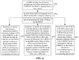
- FIG. 6 is a flowchart showing another method for searching a CORESET for RMSI, according to some embodiments of the present disclosure. As shown in FIG. 6 , after S 502 , the method may further include S 504 or S 505 .
- the CORESET for the RMSI is searched in a corresponding frequency domain and in a corresponding time domain.
- the UE searches the CORESET for the RMSI in the corresponding frequency domain and in the corresponding time domain according to a TDM manner.
- the CORESET for the RMSI is searched in a frequency domain which is lower than or higher than a predetermined frequency domain corresponding to the received SSB and in a corresponding time domain.
- the UE may search the CORESET for the RMSI in a frequency domain adjacent to a frequency domain where the SSB is located and in a corresponding time domain, namely searching the CORESET for the RMSI in the frequency domain which is lower than or higher than the predetermined frequency domain corresponding to the received SSB and in a corresponding time domain.
- the CORESET for the RMSI is searched according to obtained information, and an implementation manner is simple.
- FIG. 7 is a flowchart showing another method for searching a CORESET for RMSI, according to some embodiments of the present disclosure. As shown in FIG. 7 , after S 503 , S 504 or S 505 , the method may further include the following blocks.
- the information of the other channel may be acquired according to the received offset value between the PRB grid of another channel and the PRB grid of the SSB, and an implementation manner is simple.
- FIG. 8 is a block diagram of a device for information indication, according to some embodiments of the present disclosure.
- the device may be in a base station. As shown in FIG. 8 , the device includes a determination portion 81 , an indication portion 82 and a first sending portion 83 .
- the determination portion 81 is configured to determine whether a configured SCS of an SSB is less than an SCS of a common CORESET for RMSI corresponding to the SSB and whether time-frequency multiplexing indication information, in a PBCH of the SSB, of the CORESET for the RMSI indicates TDM of the CORESET for the RMSI and the SSB.
- the time-frequency multiplexing indication information of the CORESET for the RMSI is in the PBCH of the corresponding SSB, and the time-frequency multiplexing indication information is configured to indicate TDM or FDM of the CORESET for the RMSI and the SSB.
- the time-frequency multiplexing indication information of the CORESET for the RMSI may be shown in Table 1.
- the indication portion 82 is configured to, responsive to that the determination portion 81 determines that the SCS of the SSB is less than the SCS of the CORESET for the RMSI and the time-frequency multiplexing indication information indicates TDM of the CORESET for the RMSI and the SSB, indicate an offset value between the PRB grid of the CORESET for the RMSI and the PRB grid of the SSB through the time-frequency multiplexing indication information.
- the time-frequency multiplexing indication information includes first time-frequency multiplexing indication information and second time-frequency multiplexing indication information, and both the first time-frequency multiplexing indication information and the second time-frequency multiplexing indication information indicate TDM of the CORESET for the RMSI and the SSB.
- the first time-frequency multiplexing indication information may be one condition of TDM, i.e., one condition corresponding to index 2 or 3 in Table 1
- the second time-frequency multiplexing indication information may be another condition of TDM, i.e., the other condition corresponding to index 2 or 3 in Table 1.
- UE calculates an offset value of the two according to a PRB of the CORESET for the RMSI.
- a granularity of 1 PRB offset, calculated by the UE, of the CORESET for the RMSI is relatively great, and an offset may be an offset of PRBs of two SSBs, so that two conditions are required to be indicated. The two conditions are shown in FIG. 2A and FIG. 2B .
- the offset value between the PRB grid of the CORESET for the RMSI and the PRB grid of the SSB may be indicated through the first time-frequency multiplexing indication information or the second time-frequency multiplexing indication information.
- the condition shown in FIG. 2A may be indicated through the time-frequency multiplexing indication information represented with index 2 or 10 in Table 1
- the condition shown in FIG. 2B may be indicated through the time-frequency multiplexing indication information represented with index 3 or 11 in Table 1.
- the condition shown in FIG. 2A may also be indicated through the time-frequency multiplexing indication information represented with index 3 or 11 in Table 1
- the condition shown in FIG. 2B may also be indicated through the time-frequency multiplexing indication information represented with index 2 or 10 in Table 1.
- the first sending portion 83 is configured to send the SSB carrying the time-frequency multiplexing indication information configured for the indication portion 82 to indicate the offset value between the PRB grid of the CORESET for the RMSI and the PRB grid of the SSB to UE in a beam scanning manner.
- the offset value between the PRB grid of the CORESET for the RMSI and the PRB grid of the SSB is indicated through the time-frequency multiplexing indication information, namely the offset value between the PRB grid of the CORESET for the RMSI and the PRB grid of the SSB is indicated by use of the time-frequency multiplexing indication information, so that the purpose of reducing bits overhead is achieved.
- FIG. 9A is a block diagram of another device for information indication, according to some embodiments of the present disclosure. As shown in FIG. 9A , based on the embodiment shown in FIG. 8 , the device may further include a second sending portion 84 or a third sending portion 85 .
- the second sending portion 84 is configured to, responsive to that the determination portion 81 determines that the SCS of the SSB is greater than or equal to the SCS of the CORESET for the RMSI and the time-frequency multiplexing indication information indicates TDM of the CORESET for the RMSI and the SSB, send the SSB carrying the time-frequency multiplexing indication information to the UE in the beam scanning manner.
- the offset value between the PRB grid of the CORESET for the RMSI and the PRB grid of the SSB is not required to be indicated through the time-frequency multiplexing indication information.
- the third sending portion 85 is configured to, responsive to that the determination portion 81 determines that the time-frequency multiplexing indication information indicates FDM of the CORESET for the RMSI and the SSB, send the SSB carrying the time-frequency multiplexing indication information to the UE in the beam scanning manner.
- the time-frequency multiplexing indication information indicates FDM of the CORESET for the RMSI and the SSB
- PRBs of the CORESET for the RMSI and PRB of the SSB are adjacent.
- the SSB carrying the time-frequency multiplexing indication information is directly sent to the UE in the beam scanning manner such that the base station may also searches the CORESET for the RMSI without knowing the offset value between the PRB grid of the CORESET for the RMSI and the PRB grid of the SSB.
- FIG. 9B is a block diagram of another device for information indication, according to some embodiments of the present disclosure. As shown in FIG. 9B , based on the embodiment shown in FIG. 8 or FIG. 9A , the device may further include a fourth sending portion 86 .
- the fourth sending portion 86 is configured to, after the first sending portion 83 , the second sending portion 84 or the third sending portion 85 sends the SSB carrying the time-frequency multiplexing indication information to the UE in the beam scanning manner, responsive to determining that an SCS of other channel is greater than the SCS of the SSB, send an offset value between a PRB grid of the other channel and the PRB grid of the SSB to the UE through signaling.
- the base station may further send offset value between the PRB grid of the other channel and the PRB grid of the SSB to the UE via the signaling, for example, sending an offset value between a PRB grid of a PRACH and the PRB grid of the SSB.
- the offset value between the PRB grid of the other channel and the PRB grid of the SSB is sent to the UE via the signaling such that the UE, after searching the CORESET for the RMSI, may acquire information of the other channel.
- FIG. 10 is a block diagram of a device for searching a CORESET for RMSI, according to some embodiments of the present disclosure.
- the device may be in UE.
- the device includes a first receiving portion 110 , a determination and parsing portion 120 and an acquisition and searching portion 130 .
- the first receiving portion 110 is configured to receive an SSB carrying time-frequency multiplexing indication information of a CORESET for RMSI from a base station, the time-frequency multiplexing indication information being in a PBCH of the SSB.
- the determination and parsing portion 120 is configured to determine an SCS of the SSB received by the first receiving portion 110 and parse the PBCH of the SSB to obtain an SCS and time-frequency multiplexing indication information of the CORESET for the RMSI.
- the UE may try to parse a synchronization signal by using two predetermined SCSs of a frequency band where the SSB is located and determine the SCS through which the synchronization signal is correctly parsed as the SCS of the SSB, and then may parse the PBCH of the SSB to obtain the SCS and time-frequency multiplexing indication information of the CORESET for the RMSI.
- the acquisition and searching portion 130 is configured to, responsive to that the SCS, determined by the determination and parsing portion 120 , of the SSB is less than the SCS of the CORESET for the RMSI and the time-frequency multiplexing indication information indicates TDM of the CORESET for the RMSI and the SSB, acquire an offset value between the PRB grid of the CORESET for the RMSI and the PRB grid of the SSB from the time-frequency multiplexing indication information and search the CORESET for the RMSI in a corresponding frequency domain according to the offset value between the PRB grid of the CORESET for the RMSI and the PRB grid of the SSB.
- the UE may know that the time-frequency multiplexing indication information may indicate the offset value between the PRB grid of the CORESET for the RMSI and the PRB grid of the SSB, and thus acquires the offset value between the PRB grid of the CORESET for the RMSI and the PRB grid of the SSB from the time-frequency multiplexing indication information and searches the CORESET for the RMSI in a corresponding frequency domain according to the offset value between the PRB grid of the CORESET for the RMSI and the PRB grid of the SSB.
- the offset value between the PRB grid of the CORESET for the RMSI and the PRB grid of the SSB is acquired from the time-frequency multiplexing indication information, and the CORESET for the RMSI is searched in the corresponding frequency domain according to the offset value between the PRB grid of the CORESET for the RMSI and the PRB grid of the SSB, namely the UE may search the CORESET for the RMSI without any additional bits overhead.
- FIG. 11A is a block diagram of another device for searching a CORESET for RMSI, according to some embodiments of the present disclosure. As shown in FIG. 11A , based on the embodiment shown in FIG. 10 , the device may further include a first searching portion 140 or a second searching portion 150 .
- the first searching portion 140 is configured to, responsive to that the SCS, determined by the determination and parsing portion 120 , of the SSB is greater than or equal to the SCS of the CORESET for the RMSI and the time-frequency multiplexing indication information indicates TDM of the CORESET for the RMSI and the SSB, search the CORESET for the RMSI in a corresponding frequency domain and in a corresponding time domain.
- the UE searches the CORESET for the RMSI in the corresponding frequency domain and in the corresponding time domain according to a TDM manner.
- the second searching portion 150 is configured to, responsive to that the time-frequency multiplexing indication information determined by the determination and parsing portion 120 indicates FDM of the CORESET for the RMSI and the SSB, search the CORESET for the RMSI in a frequency domain which is lower than or higher than a predetermined frequency domain corresponding to the received SSB and in a corresponding time domain.
- the UE may search the CORESET for the RMSI in a frequency domain adjacent to a frequency domain where the SSB is located and in a corresponding time domain, namely searching the CORESET for the RMSI in the frequency domain which is lower than or higher than the predetermined frequency domain corresponding to the received SSB and in a corresponding time domain.
- the CORESET for the RMSI is searched according to obtained information, and an implementation manner is simple.
- FIG. 11B is a block diagram of another device for searching a CORESET for RMSI, according to some embodiments. As shown in FIG. 11B , based on the embodiment shown in FIG. 10 or FIG. 11A , the device may further include a second receiving portion 160 and an acquisition portion 170 .
- the second receiving portion 160 is configured to, after the acquisition and searching portion 130 , the first searching portion 140 or the second searching portion 150 searches the CORESET for the RMSI, receive an offset value, sent by the base station via signaling, between a PRB grid of other channel and the PRB grid of the SSB.
- the acquisition portion 170 is configured to acquire information of the other channel according to the offset value, received by the second receiving portion 160 , between a PRB grid of another channel or other channels and the PRB grid of the SSB.
- the information of the other channel may be acquired according to the received offset value between a PRB grid of another channel or other channels and the PRB grid of the SSB, and an implementation manner is simple.
- FIG. 11C is a block diagram of another device for searching a CORESET for RMSI, according to some embodiments of the present disclosure.
- the determination and parsing portion 120 may include a parsing unit 1201 and a determination unit 1202 .
- the parsing unit 1201 is configured to try to parse a synchronization signal by using two predetermined SCSs of a frequency band where the SSB is located.
- the determination unit 1202 is configured to determine the SCS through which the parsing unit 1201 correctly parses the synchronization signal as the SCS of the SSB.
- the synchronization signal is tried to be parsed by using the two predetermined SCSs of the frequency band where the SSB is located, and the SCS through which the synchronization signal is correctly parsed is determined as the SCS of the SSB.
- An implementation manner is simple, and a condition is provided for subsequently comparing the SCS of the SSB and the SCS of the CORESET for the RMSI.
- FIG. 12 is a block diagram of a device for searching a CORESET for RMSI, according to some embodiments of the present disclosure.
- the device 1200 may be UE such as a mobile phone, a computer, a digital broadcast terminal, a messaging device, a gaming console, a tablet, a medical device, exercise equipment and a personal digital assistant.
- the device 1200 may include one or more of the following components: a processing component 1202 , a memory 1204 , a power component 1206 , a multimedia component 1208 , an audio component 1210 , an Input/Output (I/O) interface 1212 , a sensor component 1214 , and a communication component 1216 .
- a processing component 1202 a memory 1204 , a power component 1206 , a multimedia component 1208 , an audio component 1210 , an Input/Output (I/O) interface 1212 , a sensor component 1214 , and a communication component 1216 .
- the processing component 1202 typically controls overall operations of the device 1200 , such as the operations associated with display, telephone calls, data communications, camera operations, and recording operations.
- the processing component 1202 may include one or more processors 1220 to execute instructions to perform all or part of the steps in the abovementioned method.
- the processing component 1202 may include one or more modules which facilitate interaction between the processing component 1202 and the other components.
- the processing component 1202 may include a multimedia module to facilitate interaction between the multimedia component 1208 and the processing component 1202 .
- One processor 1220 in the processing component 1202 may be configured to:
- time-frequency multiplexing indication information of a CORESET for RMSI from a base station, the time-frequency multiplexing indication information being in a PBCH of the SSB;
- the time-frequency multiplexing indication information indicates TDM of the CORESET for the RMSI and the SSB, acquire an offset value between the PRB grid of the CORESET for the RMSI and the PRB grid of the SSB from the time-frequency multiplexing indication information, and search the CORESET for the RMSI in a corresponding frequency domain according to the offset value between the PRB grid of the CORESET for the RMSI and the PRB grid of the SSB.
- the memory 1204 is configured to store various types of data to support the operation of the device 1200 . Examples of such data include instructions for any disclosures or methods operated on the device 1200 , contact data, phonebook data, messages, pictures, video, etc.
- the memory 1204 may be implemented by any type of volatile or non-volatile memory devices, or a combination thereof, such as an Electrically Erasable Programmable Read-Only Memory (EEPROM), an Erasable Programmable Read-Only Memory (EPROM), a Programmable Read-Only Memory (PROM), a Read-Only Memory (ROM), a magnetic memory, a flash memory, and a magnetic or optical disk.
- EEPROM Electrically Erasable Programmable Read-Only Memory
- EPROM Erasable Programmable Read-Only Memory
- PROM Programmable Read-Only Memory
- ROM Read-Only Memory
- magnetic memory a magnetic memory
- flash memory and a magnetic or optical disk.
- the power component 1206 provides power for various components of the device 1200 .
- the power component 1206 may include a power management system, one or more power supplies, and other components associated with generation, management and distribution of power for the device 1200 .
- the multimedia component 1208 includes a screen providing an output interface between the device 1200 and a user.
- the screen may include a Liquid Crystal Display (LCD) and a Touch Panel (TP).
- LCD Liquid Crystal Display
- TP Touch Panel
- OLED organic light-emitting diode
- the screen may be implemented as a touch screen to receive an input signal from the user.
- the TP includes one or more touch sensors to sense touches, swipes and gestures on the TP. The touch sensors may not only sense a boundary of a touch or swipe action but also detect a duration and pressure associated with the touch or swipe action.
- the multimedia component 1208 includes a front camera and/or a rear camera.
- the front camera and/or the rear camera may receive external multimedia data when the device 1200 is in an operation mode, such as a photographing mode or a video mode.
- an operation mode such as a photographing mode or a video mode.
- Each of the front camera and the rear camera may be a fixed optical lens system or have focusing and optical zooming capabilities.
- the audio component 1210 is configured to output and/or input an audio signal.
- the audio component 1210 includes a Microphone (MIC), and the MIC is configured to receive an external audio signal when the device 1200 is in the operation mode, such as a call mode, a recording mode and a voice recognition mode.
- the received audio signal may further be stored in the memory 1204 or sent through the communication component 1216 .
- the audio component 1210 further includes a speaker configured to output the audio signal.
- the I/O interface 1212 provides an interface between the processing component 1202 and a peripheral interface module, and the peripheral interface module may be a keyboard, a click wheel, a button and the like.
- the button may include, but not limited to: a home button, a volume button, a starting button and a locking button.
- the sensor component 1214 includes one or more sensors configured to provide status assessment in various aspects for the device 1200 .
- the sensor component 1214 may detect an on/off status of the device 1200 and relative positioning of components, such as a display and small keyboard of the device 1200 , and the sensor component 1214 may further detect a change in a position of the device 1200 or a component of the device 1200 , presence or absence of contact between the user and the device 1200 , orientation or acceleration/deceleration of the device 1200 and a change in temperature of the device 1200 .
- the sensor component 1214 may include a proximity sensor configured to detect presence of an object nearby without any physical contact.
- the sensor component 1214 may also include a light sensor, such as a Complementary Metal Oxide Semiconductor (CMOS) or Charge Coupled Device (CCD) image sensor, configured for use in an imaging disclosure.
- CMOS Complementary Metal Oxide Semiconductor
- CCD Charge Coupled Device
- the sensor component 1214 may also include an acceleration sensor, a gyroscope sensor, a magnetic sensor, a pressure sensor or a temperature sensor.
- the communication component 1216 is configured to facilitate wired or wireless communication between the device 1200 and another device.
- the device 1200 may access a communication-standard-based wireless network, such as a Wireless Fidelity (Wi-Fi) network, a 2nd-Generation (2G) or 3rd-Generation (3G), 4 th -Generation (4G), or 5 th -Generation (5G) network or a combination thereof.
- Wi-Fi Wireless Fidelity
- 3G 3rd-Generation
- 4G 4 th -Generation
- 5G 5 th -Generation
- the communication component 1216 receives a broadcast signal or broadcast associated information from an external broadcast management system through a broadcast channel.
- the communication component 1216 further includes a Near Field Communication (NFC) module to facilitate short-range communication.
- NFC Near Field Communication
- the NFC module may be implemented based on a Radio Frequency Identification (RFID) technology, an Infrared Data Association (IrDA) technology, an Ultra-Wide Band (UWB) technology, a Bluetooth (BT) technology and another technology.
- RFID Radio Frequency Identification
- IrDA Infrared Data Association
- UWB Ultra-Wide Band
- BT Bluetooth
- the device 1200 may be implemented by one or more Application Specific Integrated Circuits (ASICs), Digital Signal Processors (DSPs), Digital Signal Processing Devices (DSPDs), Programmable Logic Devices (PLDs), Field Programmable Gate Arrays (FPGAs), controllers, micro-controllers, microprocessors or other electronic components, and is configured to execute the abovementioned method.
- ASICs Application Specific Integrated Circuits
- DSPs Digital Signal Processors
- DSPDs Digital Signal Processing Devices
- PLDs Programmable Logic Devices
- FPGAs Field Programmable Gate Arrays
- controllers micro-controllers, microprocessors or other electronic components, and is configured to execute the abovementioned method.
- a non-transitory computer-readable storage medium including an instruction such as the memory 1204 including an instruction, and the instruction may be executed by the processor 1220 of the device 1200 to implement the abovementioned method.
- the non-transitory computer-readable storage medium may be a ROM, a Compact Disc Read-Only Memory (CD-ROM), a magnetic tape, a floppy disc, an optical data storage device and the like.
- FIG. 13 is a block diagram of a device for information indication, according to some embodiments of the present disclosure.
- the device 1300 may be provided as a base station.
- the device 1300 includes a processing component 1322 , a wireless transmitting/receiving component 1324 , an antenna component 1326 and a wireless interface-specific signal processing part, and the processing component 1322 may further include one or more processors.
- One processor in the processing component 1322 may be configured to:
- the time-frequency multiplexing indication information indicates TDM of the CORESET for the RMSI and the SSB, indicate an offset value between the PRB grid of the CORESET for the RMSI and the PRB grid of the SSB through the time-frequency multiplexing indication information;
- non-transitory computer-readable storage medium including an instruction, and the instruction may be executed by the processing component 1322 of the device 1300 to implement the method for information indication.
- the non-transitory computer-readable storage medium may be a ROM, a CD-ROM, a magnetic tape, a floppy disc, an optical data storage device and the like.
- the device embodiments substantially correspond to the method embodiments, and thus related parts refer to part of descriptions of the method embodiments.
- the device embodiment described above is only schematic, units described as separate parts therein may or may not be physically separated, and parts displayed as units may or may not be physical units, and namely may be located in the same place or may also be distributed to multiple network units. Part or all of the portions therein may be selected according to a practical requirement to achieve the purpose of the solutions of the embodiments. Those of ordinary skill in the art may understand and implement without creative work.
- modules may have modular configurations, or are composed of discrete components, but nonetheless can be referred to as “modules” in general.
- the “components,” “modules,” “blocks,” “portions,” or “units” referred to herein may or may not be in modular forms.
- the terms “installed,” “connected,” “coupled,” “fixed” and the like shall be understood broadly, and can be either a fixed connection or a detachable connection, or integrated, unless otherwise explicitly defined. These terms can refer to mechanical or electrical connections, or both. Such connections can be direct connections or indirect connections through an intermediate medium. These terms can also refer to the internal connections or the interactions between elements. The specific meanings of the above terms in the present disclosure can be understood by those of ordinary skill in the art on a case-by-case basis.
- the terms “one embodiment,” “some embodiments,” “example,” “specific example,” or “some examples,” and the like can indicate a specific feature described in connection with the embodiment or example, a structure, a material or feature included in at least one embodiment or example.
- the schematic representation of the above terms is not necessarily directed to the same embodiment or example.
- control and/or interface software or app can be provided in a form of a non-transitory computer-readable storage medium having instructions stored thereon is further provided.
- the non-transitory computer-readable storage medium can be a ROM, a CD-ROM, a magnetic tape, a floppy disk, optical data storage equipment, a flash drive such as a USB drive or an SD card, and the like.
- Implementations of the subject matter and the operations described in this disclosure can be implemented in digital electronic circuitry, or in computer software, firmware, or hardware, including the structures disclosed herein and their structural equivalents, or in combinations of one or more of them. Implementations of the subject matter described in this disclosure can be implemented as one or more computer programs, i.e., one or more portions of computer program instructions, encoded on one or more computer storage medium for execution by, or to control the operation of, data processing apparatus.
- the program instructions can be encoded on an artificially-generated propagated signal, e.g., a machine-generated electrical, optical, or electromagnetic signal, which is generated to encode information for transmission to suitable receiver apparatus for execution by a data processing apparatus.
- an artificially-generated propagated signal e.g., a machine-generated electrical, optical, or electromagnetic signal, which is generated to encode information for transmission to suitable receiver apparatus for execution by a data processing apparatus.
- a computer storage medium can be, or be included in, a computer-readable storage device, a computer-readable storage substrate, a random or serial access memory array or device, or a combination of one or more of them.
- a computer storage medium is not a propagated signal
- a computer storage medium can be a source or destination of computer program instructions encoded in an artificially-generated propagated signal.
- the computer storage medium can also be, or be included in, one or more separate components or media (e.g., multiple CDs, disks, drives, or other storage devices). Accordingly, the computer storage medium can be tangible.
- the operations described in this disclosure can be implemented as operations performed by a data processing apparatus on data stored on one or more computer-readable storage devices or received from other sources.
- the devices in this disclosure can include special purpose logic circuitry, e.g., an FPGA (field-programmable gate array), or an ASIC (application-specific integrated circuit).
- the device can also include, in addition to hardware, code that creates an execution environment for the computer program in question, e.g., code that constitutes processor firmware, a protocol stack, a database management system, an operating system, a cross-platform runtime environment, a virtual machine, or a combination of one or more of them.
- the devices and execution environment can realize various different computing model infrastructures, such as web services, distributed computing, and grid computing infrastructures.
- a computer program (also known as a program, software, software application, app, script, or code) can be written in any form of programming language, including compiled or interpreted languages, declarative or procedural languages, and it can be deployed in any form, including as a stand-alone program or as a portion, component, subroutine, object, or other portion suitable for use in a computing environment.
- a computer program can, but need not, correspond to a file in a file system.
- a program can be stored in a portion of a file that holds other programs or data (e.g., one or more scripts stored in a markup language document), in a single file dedicated to the program in question, or in multiple coordinated files (e.g., files that store one or more portions, sub-programs, or portions of code).
- a computer program can be deployed to be executed on one computer or on multiple computers that are located at one site or distributed across multiple sites and interconnected by a communication network.
- the processes and logic flows described in this disclosure can be performed by one or more programmable processors executing one or more computer programs to perform actions by operating on input data and generating output.
- the processes and logic flows can also be performed by, and apparatus can also be implemented as, special purpose logic circuitry, e.g., an FPGA, or an ASIC.
- processors or processing circuits suitable for the execution of a computer program include, by way of example, both general and special purpose microprocessors, and any one or more processors of any kind of digital computer.
- a processor will receive instructions and data from a read-only memory, or a random-access memory, or both.
- Elements of a computer can include a processor configured to perform actions in accordance with instructions and one or more memory devices for storing instructions and data.
- a computer will also include, or be operatively coupled to receive data from or transfer data to, or both, one or more mass storage devices for storing data, e.g., magnetic, magneto-optical disks, or optical disks.
- mass storage devices for storing data
- a computer need not have such devices.
- a computer can be embedded in another device, e.g., a mobile telephone, a personal digital assistant (PDA), a mobile audio or video player, a game console, a Global Positioning System (GPS) receiver, or a portable storage device (e.g., a universal serial bus (USB) flash drive), to name just a few.
- PDA personal digital assistant
- GPS Global Positioning System
- USB universal serial bus
- Devices suitable for storing computer program instructions and data include all forms of non-volatile memory, media and memory devices, including by way of example semiconductor memory devices, e.g., EPROM, EEPROM, and flash memory devices; magnetic disks, e.g., internal hard disks or removable disks; magneto-optical disks; and CD-ROM and DVD-ROM disks.
- semiconductor memory devices e.g., EPROM, EEPROM, and flash memory devices
- magnetic disks e.g., internal hard disks or removable disks
- magneto-optical disks e.g., CD-ROM and DVD-ROM disks.
- the processor and the memory can be supplemented by, or incorporated in, special purpose logic circuitry.
- implementations of the subject matter described in this specification can be implemented with a computer and/or a display device, e.g., a VR/AR device, a head-mount display (HMD) device, a head-up display (HUD) device, smart eyewear (e.g., glasses), a CRT (cathode-ray tube), LCD (liquid-crystal display), OLED (organic light emitting diode), or any other monitor for displaying information to the user and a keyboard, a pointing device, e.g., a mouse, trackball, etc., or a touch screen, touch pad, etc., by which the user can provide input to the computer.
- a display device e.g., a VR/AR device, a head-mount display (HMD) device, a head-up display (HUD) device, smart eyewear (e.g., glasses), a CRT (cathode-ray tube), LCD (liquid-crystal display), OLED (organic light emitting dio
- Implementations of the subject matter described in this specification can be implemented in a computing system that includes a back-end component, e.g., as a data server, or that includes a middleware component, e.g., an application server, or that includes a front-end component, e.g., a client computer having a graphical user interface or a Web browser through which a user can interact with an implementation of the subject matter described in this specification, or any combination of one or more such back-end, middleware, or front-end components.
- a back-end component e.g., as a data server
- a middleware component e.g., an application server
- a front-end component e.g., a client computer having a graphical user interface or a Web browser through which a user can interact with an implementation of the subject matter described in this specification, or any combination of one or more such back-end, middleware, or front-end components.
- the components of the system can be interconnected by any form or medium of digital data communication, e.g., a communication network.
- Examples of communication networks include a local area network (“LAN”) and a wide area network (“WAN”), an inter-network (e.g., the Internet), and peer-to-peer networks (e.g., ad hoc peer-to-peer networks).
- a plurality” or “multiple” as referred to herein means two or more.
- “And/or,” describing the association relationship of the associated objects, indicates that there may be three relationships, for example, A and/or B may indicate that there are three cases where A exists separately, A and B exist at the same time, and B exists separately.
- the character “/” generally indicates that the contextual objects are in an “or” relationship.
- first and second are used for descriptive purposes only and are not to be construed as indicating or implying a relative importance or implicitly indicating the number of technical features indicated. Thus, elements referred to as “first” and “second” may include one or more of the features either explicitly or implicitly. In the description of the present disclosure, “a plurality” indicates two or more unless specifically defined otherwise.
- a first element being “on” a second element may indicate direct contact between the first and second elements, without contact, or indirect geometrical relationship through one or more intermediate media or layers, unless otherwise explicitly stated and defined.
- a first element being “under,” “underneath” or “beneath” a second element may indicate direct contact between the first and second elements, without contact, or indirect geometrical relationship through one or more intermediate media or layers, unless otherwise explicitly stated and defined.
Landscapes
- Engineering & Computer Science (AREA)
- Signal Processing (AREA)
- Computer Networks & Wireless Communication (AREA)
- Mobile Radio Communication Systems (AREA)
Abstract
Description
| TABLE 1 |
| Index and Meaning of Time-Frequency Multiplexing |
| Indication Information of CORESET for RMSI |
| Index | Meaning |
| 0 (00) | FDM is implemented for the CORESET for the RMSI and the |
| SSB, and the frequency band where the CORESET for the | |
| RMSI is located is higher than the band where the SSB | |
| is located | |
| 1 (01) | FDM is implemented for the CORESET for the RMSI and the |
| SSB, and the frequency band where the CORESET for the | |
| RMSI is located is lower than the band where the SSB | |
| is located | |
| 2 (10) | First condition of TDM of the CORESET for the RMSI |
| and the SSB | |
| 3 (11) | Second condition of TDM of the CORESET for the RMSI |
| and the SSB | |
Claims (12)
Applications Claiming Priority (1)
| Application Number | Priority Date | Filing Date | Title |
|---|---|---|---|
| PCT/CN2017/113201 WO2019100402A1 (en) | 2017-11-27 | 2017-11-27 | Method and apparatus for indicating information, base station, and user equipment |
Related Parent Applications (1)
| Application Number | Title | Priority Date | Filing Date |
|---|---|---|---|
| PCT/CN2017/113201 Continuation WO2019100402A1 (en) | 2017-11-27 | 2017-11-27 | Method and apparatus for indicating information, base station, and user equipment |
Publications (2)
| Publication Number | Publication Date |
|---|---|
| US20200275451A1 US20200275451A1 (en) | 2020-08-27 |
| US11470617B2 true US11470617B2 (en) | 2022-10-11 |
Family
ID=65530651
Family Applications (1)
| Application Number | Title | Priority Date | Filing Date |
|---|---|---|---|
| US16/870,919 Active 2038-03-08 US11470617B2 (en) | 2017-11-27 | 2020-05-09 | Method and apparatus for indicating information, base station, and user equipment |
Country Status (3)
| Country | Link |
|---|---|
| US (1) | US11470617B2 (en) |
| CN (1) | CN109451797B (en) |
| WO (1) | WO2019100402A1 (en) |
Families Citing this family (7)
| Publication number | Priority date | Publication date | Assignee | Title |
|---|---|---|---|---|
| WO2018142978A1 (en) * | 2017-02-03 | 2018-08-09 | 株式会社Nttドコモ | Base station and method for transmitting synchronization signal |
| US11398874B2 (en) * | 2017-11-29 | 2022-07-26 | Lg Electronics Inc. | Method and apparatus for measuring signal quality in wireless communication system |
| US10912047B2 (en) * | 2018-03-29 | 2021-02-02 | Lg Electronics Inc. | Method and apparatus for transmitting and receiving system information |
| WO2021031002A1 (en) * | 2019-08-16 | 2021-02-25 | 华为技术有限公司 | Method and apparatus for indicating control information |
| CN114586429B (en) * | 2019-10-14 | 2025-03-07 | Oppo广东移动通信有限公司 | Wireless communication method, terminal device and network device |
| CN113271654B (en) * | 2020-02-14 | 2022-11-04 | 展讯通信(上海)有限公司 | Configuration method and device, electronic device, and storage medium for monitoring timing of PDCCH |
| US12408130B2 (en) | 2020-07-31 | 2025-09-02 | Beijing Xiaomi Mobile Software Co., Ltd. | Method and apparatus for determining offset indication, and method and apparatus for determining offset |
Citations (19)
| Publication number | Priority date | Publication date | Assignee | Title |
|---|---|---|---|---|
| CN104303478A (en) | 2012-05-11 | 2015-01-21 | 英特尔公司 | Synchronization signals scheduled in new carrier types |
| US20170142771A1 (en) | 2009-11-04 | 2017-05-18 | Telefonaktiebolaget L M Ericsson (Publ) | Signaling for flexible carrier aggregation |
| WO2017139540A1 (en) | 2016-02-11 | 2017-08-17 | Qualcomm Incorporated | Multi-prb operation for narrowband systems |
| CN107211238A (en) | 2015-05-18 | 2017-09-26 | 株式会社Kt | Method and apparatus for sending and receiving system information |
| US20180337755A1 (en) * | 2017-05-16 | 2018-11-22 | Qualcomm Incorporated | Techniques and apparatuses for reusing remaining minimum system information configuration bits to signal a synchronization signal block location |
| US20190028914A1 (en) * | 2017-07-21 | 2019-01-24 | Htc Corporation | Device and Method of Handling a Measurement Configuration and a Reporting |
| US20190028940A1 (en) * | 2017-07-21 | 2019-01-24 | Htc Corporation | Device and Method of Handling a Handover |
| US20190069322A1 (en) * | 2017-10-27 | 2019-02-28 | Alexei Davydov | Control resource set information in physical broadcast channel |
| US20190082431A1 (en) * | 2017-09-11 | 2019-03-14 | Lg Electronics Inc. | Method and apparatus for transmitting downlink control information in wireless communication system |
| US20190132170A1 (en) * | 2017-11-01 | 2019-05-02 | Samsung Electronics Co., Ltd. | Method and apparatus of nr rmsi coreset configuration in mib |
| US20190140880A1 (en) * | 2017-08-11 | 2019-05-09 | Huawei Technologies Co., Ltd. | Communication Method, Communications Apparatus, and Communications System |
| US20190150121A1 (en) * | 2017-11-16 | 2019-05-16 | Huawei Technologies Co., Ltd. | Configuration of the initial active bandwidth part for initial network access |
| US20190150068A1 (en) * | 2017-11-15 | 2019-05-16 | Qualcomm Incorporated | Transmission of physical broadcast channel for new radio |
| US20190159226A1 (en) * | 2017-11-17 | 2019-05-23 | Qualcomm Incorporated | Designs for remaining minimum system information (rmsi) control resource set (coreset) and other system information (osi) coreset |
| US20190166611A1 (en) * | 2017-11-16 | 2019-05-30 | Lg Electronics Inc. | Method and apparatus for transmitting pbch and method and apparatus for receiving pbch |
| US20200244530A1 (en) * | 2017-11-17 | 2020-07-30 | Telefonaktiebolaget Lm Ericsson (Publ) | Compressed table-based configuration of remaining minimum system information coreset in a new radio physical broadcast channel |
| US20200296656A1 (en) * | 2017-09-08 | 2020-09-17 | Samsung Electronics Co., Ltd. | A method and system for handling radio link monitoring (rlm) using bandwidth part (bwp) configurations |
| US20210007086A1 (en) * | 2017-11-17 | 2021-01-07 | Zte Corporation | Information sending method and device and information receiving method and device |
| US20210185683A1 (en) * | 2017-11-17 | 2021-06-17 | Telefonaktiebolaget Lm Ericsson (Publ) | Efficient CORESET Configuration |
-
2017
- 2017-11-27 CN CN201780001900.XA patent/CN109451797B/en active Active
- 2017-11-27 WO PCT/CN2017/113201 patent/WO2019100402A1/en not_active Ceased
-
2020
- 2020-05-09 US US16/870,919 patent/US11470617B2/en active Active
Patent Citations (19)
| Publication number | Priority date | Publication date | Assignee | Title |
|---|---|---|---|---|
| US20170142771A1 (en) | 2009-11-04 | 2017-05-18 | Telefonaktiebolaget L M Ericsson (Publ) | Signaling for flexible carrier aggregation |
| CN104303478A (en) | 2012-05-11 | 2015-01-21 | 英特尔公司 | Synchronization signals scheduled in new carrier types |
| CN107211238A (en) | 2015-05-18 | 2017-09-26 | 株式会社Kt | Method and apparatus for sending and receiving system information |
| WO2017139540A1 (en) | 2016-02-11 | 2017-08-17 | Qualcomm Incorporated | Multi-prb operation for narrowband systems |
| US20180337755A1 (en) * | 2017-05-16 | 2018-11-22 | Qualcomm Incorporated | Techniques and apparatuses for reusing remaining minimum system information configuration bits to signal a synchronization signal block location |
| US20190028914A1 (en) * | 2017-07-21 | 2019-01-24 | Htc Corporation | Device and Method of Handling a Measurement Configuration and a Reporting |
| US20190028940A1 (en) * | 2017-07-21 | 2019-01-24 | Htc Corporation | Device and Method of Handling a Handover |
| US20190140880A1 (en) * | 2017-08-11 | 2019-05-09 | Huawei Technologies Co., Ltd. | Communication Method, Communications Apparatus, and Communications System |
| US20200296656A1 (en) * | 2017-09-08 | 2020-09-17 | Samsung Electronics Co., Ltd. | A method and system for handling radio link monitoring (rlm) using bandwidth part (bwp) configurations |
| US20190082431A1 (en) * | 2017-09-11 | 2019-03-14 | Lg Electronics Inc. | Method and apparatus for transmitting downlink control information in wireless communication system |
| US20190069322A1 (en) * | 2017-10-27 | 2019-02-28 | Alexei Davydov | Control resource set information in physical broadcast channel |
| US20190132170A1 (en) * | 2017-11-01 | 2019-05-02 | Samsung Electronics Co., Ltd. | Method and apparatus of nr rmsi coreset configuration in mib |
| US20190150068A1 (en) * | 2017-11-15 | 2019-05-16 | Qualcomm Incorporated | Transmission of physical broadcast channel for new radio |
| US20190150121A1 (en) * | 2017-11-16 | 2019-05-16 | Huawei Technologies Co., Ltd. | Configuration of the initial active bandwidth part for initial network access |
| US20190166611A1 (en) * | 2017-11-16 | 2019-05-30 | Lg Electronics Inc. | Method and apparatus for transmitting pbch and method and apparatus for receiving pbch |
| US20190159226A1 (en) * | 2017-11-17 | 2019-05-23 | Qualcomm Incorporated | Designs for remaining minimum system information (rmsi) control resource set (coreset) and other system information (osi) coreset |
| US20200244530A1 (en) * | 2017-11-17 | 2020-07-30 | Telefonaktiebolaget Lm Ericsson (Publ) | Compressed table-based configuration of remaining minimum system information coreset in a new radio physical broadcast channel |
| US20210007086A1 (en) * | 2017-11-17 | 2021-01-07 | Zte Corporation | Information sending method and device and information receiving method and device |
| US20210185683A1 (en) * | 2017-11-17 | 2021-06-17 | Telefonaktiebolaget Lm Ericsson (Publ) | Efficient CORESET Configuration |
Non-Patent Citations (8)
| Title |
|---|
| 3GPP TR 38.811V0.1.0 (Jun. 2017), 3rd Generation Partnership Project, Technical Specification Group Radio Access Network, Study on New Radio (NR) to support Non Terrestrial Networks (Release 15). |
| CMCC. "Details on PRB Grid Offset Indication" 3GPP TSG RAN WG1 Meeting 91 R1-1720581, Nov. 18, 2017 (Nov. 18, 2017), entire document. |
| English translation of the Written Opinion of the International Search Authority in the international application No. PCT/CN2017/113201, dated Aug. 15, 2018. |
| International Search Report in the international application No. PCT/CN2017/113201, dated Aug. 15, 2018. |
| Nokia, Nokia Shanghai Bell, "Remaining details on NR-PBCH", 3GPP TSG-RAN WG1 NR AH#3 R1-1716524 Nagoya, Japan, Sep. 18-21, 2017. |
| Qualcomm Incorporated, "Remaining system information delivery consideration", 3GPP TSG RAN WG1 Meeting 91 R1-1720649 Reno, Nov. 27-Dec. 1, 2017. |
| TSG RAN WG1. "Status Report to TSG: New Radio (NR) Access Technology" 3GPP TSG RAN meeting #76 RP-1711505, Jun. 8, 2017 (Jun. 8, 2017), entire document. |
| TSG RAN WG1. "Status Report to TSG: New Radio (NR) Access Technology" 3GPP TSG RAN meeting #77 RP-171783, Sep. 6, 2017 (Sep. 6, 2017), entire document. |
Also Published As
| Publication number | Publication date |
|---|---|
| US20200275451A1 (en) | 2020-08-27 |
| CN109451797A (en) | 2019-03-08 |
| CN109451797B (en) | 2021-06-04 |
| WO2019100402A1 (en) | 2019-05-31 |
Similar Documents
| Publication | Publication Date | Title |
|---|---|---|
| US11382069B2 (en) | Method for indicating relative position information of coreset of RMSI, method for obtaining coreset of RMSI, and UE | |
| US11470617B2 (en) | Method and apparatus for indicating information, base station, and user equipment | |
| US11303323B2 (en) | Frequency hopping configuration method and device | |
| US11438743B2 (en) | Method and apparatus for indicating multi-service data multiplex transmission, terminal and base station | |
| US11968723B2 (en) | Method and apparatus for random access | |
| US11337145B2 (en) | Method and device for searching for common resource set of remaining mission-critical system information | |
| US20200236612A1 (en) | Access method and device, user equipment and base station | |
| US11540113B2 (en) | Transmission configuration method and apparatus | |
| US11330572B2 (en) | Method and device for indicating multi-service data multiplex transmission, terminal and base station | |
| US11533652B2 (en) | Method and device for configuring reflective quality of service, and method and device for transmitting information | |
| US11375504B2 (en) | Method for indicating time-domain information of common control resource set of remaining minimum system information | |
| US11540160B2 (en) | Transmission capability update method and apparatus | |
| US11329949B2 (en) | Domain name parsing method, domain name parsing device and storage medium | |
| US11184078B2 (en) | Data transmission method and apparatus | |
| US11368964B2 (en) | Data transmission method, apparatus, and unmanned aerial vehicle | |
| US11601952B2 (en) | Method and apparatus for service multiplexing and transmission | |
| US11246070B2 (en) | Cell camping method, and user equipment | |
| US20210182015A1 (en) | Audio playing control method and device and storage medium | |
| US20210185595A1 (en) | Method and apparatus for indicating and determining transmission direction of transmission unit | |
| US20200367274A1 (en) | Trigger hold method and trigger hold apparatus | |
| US11382125B2 (en) | Data transmission method, device and computer readable storage medium | |
| US11317339B2 (en) | Communication control method and communication control device | |
| US11019598B1 (en) | Paging indication method and device | |
| US11375477B2 (en) | Method for determining scrambling initialization sequence of data and data descrambling method | |
| US11323558B2 (en) | Method for reducing terminal temperature, device for reducing terminal temperature, and storage medium |
Legal Events
| Date | Code | Title | Description |
|---|---|---|---|
| AS | Assignment |
Owner name: BEIJING XIAOMI MOBILE SOFTWARE CO., LTD., CHINA Free format text: ASSIGNMENT OF ASSIGNORS INTEREST;ASSIGNOR:LIU, YANG;REEL/FRAME:052618/0691 Effective date: 20200508 |
|
| FEPP | Fee payment procedure |
Free format text: ENTITY STATUS SET TO UNDISCOUNTED (ORIGINAL EVENT CODE: BIG.); ENTITY STATUS OF PATENT OWNER: LARGE ENTITY |
|
| STPP | Information on status: patent application and granting procedure in general |
Free format text: DOCKETED NEW CASE - READY FOR EXAMINATION |
|
| STPP | Information on status: patent application and granting procedure in general |
Free format text: NON FINAL ACTION MAILED |
|
| STPP | Information on status: patent application and granting procedure in general |
Free format text: RESPONSE TO NON-FINAL OFFICE ACTION ENTERED AND FORWARDED TO EXAMINER |
|
| STPP | Information on status: patent application and granting procedure in general |
Free format text: FINAL REJECTION MAILED |
|
| STPP | Information on status: patent application and granting procedure in general |
Free format text: DOCKETED NEW CASE - READY FOR EXAMINATION |
|
| STPP | Information on status: patent application and granting procedure in general |
Free format text: NOTICE OF ALLOWANCE MAILED -- APPLICATION RECEIVED IN OFFICE OF PUBLICATIONS |
|
| STPP | Information on status: patent application and granting procedure in general |
Free format text: PUBLICATIONS -- ISSUE FEE PAYMENT VERIFIED |
|
| STCF | Information on status: patent grant |
Free format text: PATENTED CASE |