US11470448B2 - Method and system to estimate and learn the location of a radio device - Google Patents
Method and system to estimate and learn the location of a radio device Download PDFInfo
- Publication number
- US11470448B2 US11470448B2 US16/937,807 US202016937807A US11470448B2 US 11470448 B2 US11470448 B2 US 11470448B2 US 202016937807 A US202016937807 A US 202016937807A US 11470448 B2 US11470448 B2 US 11470448B2
- Authority
- US
- United States
- Prior art keywords
- messages
- location
- anchors
- mobile device
- mobile
- Prior art date
- Legal status (The legal status is an assumption and is not a legal conclusion. Google has not performed a legal analysis and makes no representation as to the accuracy of the status listed.)
- Active, expires
Links
Images


Classifications
-
- G—PHYSICS
- G06—COMPUTING OR CALCULATING; COUNTING
- G06N—COMPUTING ARRANGEMENTS BASED ON SPECIFIC COMPUTATIONAL MODELS
- G06N20/00—Machine learning
- G06N20/10—Machine learning using kernel methods, e.g. support vector machines [SVM]
-
- G—PHYSICS
- G01—MEASURING; TESTING
- G01S—RADIO DIRECTION-FINDING; RADIO NAVIGATION; DETERMINING DISTANCE OR VELOCITY BY USE OF RADIO WAVES; LOCATING OR PRESENCE-DETECTING BY USE OF THE REFLECTION OR RERADIATION OF RADIO WAVES; ANALOGOUS ARRANGEMENTS USING OTHER WAVES
- G01S5/00—Position-fixing by co-ordinating two or more direction or position line determinations; Position-fixing by co-ordinating two or more distance determinations
- G01S5/02—Position-fixing by co-ordinating two or more direction or position line determinations; Position-fixing by co-ordinating two or more distance determinations using radio waves
- G01S5/0252—Radio frequency fingerprinting
- G01S5/02521—Radio frequency fingerprinting using a radio-map
- G01S5/02524—Creating or updating the radio-map
- G01S5/02525—Gathering the radio frequency fingerprints
-
- G—PHYSICS
- G01—MEASURING; TESTING
- G01S—RADIO DIRECTION-FINDING; RADIO NAVIGATION; DETERMINING DISTANCE OR VELOCITY BY USE OF RADIO WAVES; LOCATING OR PRESENCE-DETECTING BY USE OF THE REFLECTION OR RERADIATION OF RADIO WAVES; ANALOGOUS ARRANGEMENTS USING OTHER WAVES
- G01S5/00—Position-fixing by co-ordinating two or more direction or position line determinations; Position-fixing by co-ordinating two or more distance determinations
- G01S5/02—Position-fixing by co-ordinating two or more direction or position line determinations; Position-fixing by co-ordinating two or more distance determinations using radio waves
- G01S5/0252—Radio frequency fingerprinting
- G01S5/02528—Simulating radio frequency fingerprints
-
- G—PHYSICS
- G01—MEASURING; TESTING
- G01S—RADIO DIRECTION-FINDING; RADIO NAVIGATION; DETERMINING DISTANCE OR VELOCITY BY USE OF RADIO WAVES; LOCATING OR PRESENCE-DETECTING BY USE OF THE REFLECTION OR RERADIATION OF RADIO WAVES; ANALOGOUS ARRANGEMENTS USING OTHER WAVES
- G01S5/00—Position-fixing by co-ordinating two or more direction or position line determinations; Position-fixing by co-ordinating two or more distance determinations
- G01S5/02—Position-fixing by co-ordinating two or more direction or position line determinations; Position-fixing by co-ordinating two or more distance determinations using radio waves
- G01S5/06—Position of source determined by co-ordinating a plurality of position lines defined by path-difference measurements
-
- G—PHYSICS
- G01—MEASURING; TESTING
- G01S—RADIO DIRECTION-FINDING; RADIO NAVIGATION; DETERMINING DISTANCE OR VELOCITY BY USE OF RADIO WAVES; LOCATING OR PRESENCE-DETECTING BY USE OF THE REFLECTION OR RERADIATION OF RADIO WAVES; ANALOGOUS ARRANGEMENTS USING OTHER WAVES
- G01S5/00—Position-fixing by co-ordinating two or more direction or position line determinations; Position-fixing by co-ordinating two or more distance determinations
- G01S5/02—Position-fixing by co-ordinating two or more direction or position line determinations; Position-fixing by co-ordinating two or more distance determinations using radio waves
- G01S5/10—Position of receiver fixed by co-ordinating a plurality of position lines defined by path-difference measurements, e.g. omega or decca systems
-
- G—PHYSICS
- G06—COMPUTING OR CALCULATING; COUNTING
- G06N—COMPUTING ARRANGEMENTS BASED ON SPECIFIC COMPUTATIONAL MODELS
- G06N20/00—Machine learning
-
- G—PHYSICS
- G06—COMPUTING OR CALCULATING; COUNTING
- G06N—COMPUTING ARRANGEMENTS BASED ON SPECIFIC COMPUTATIONAL MODELS
- G06N3/00—Computing arrangements based on biological models
- G06N3/02—Neural networks
- G06N3/08—Learning methods
- G06N3/09—Supervised learning
-
- G—PHYSICS
- G06—COMPUTING OR CALCULATING; COUNTING
- G06N—COMPUTING ARRANGEMENTS BASED ON SPECIFIC COMPUTATIONAL MODELS
- G06N5/00—Computing arrangements using knowledge-based models
- G06N5/04—Inference or reasoning models
-
- H—ELECTRICITY
- H04—ELECTRIC COMMUNICATION TECHNIQUE
- H04W—WIRELESS COMMUNICATION NETWORKS
- H04W4/00—Services specially adapted for wireless communication networks; Facilities therefor
- H04W4/02—Services making use of location information
- H04W4/021—Services related to particular areas, e.g. point of interest [POI] services, venue services or geofences
-
- H—ELECTRICITY
- H04—ELECTRIC COMMUNICATION TECHNIQUE
- H04W—WIRELESS COMMUNICATION NETWORKS
- H04W4/00—Services specially adapted for wireless communication networks; Facilities therefor
- H04W4/02—Services making use of location information
- H04W4/029—Location-based management or tracking services
-
- G—PHYSICS
- G01—MEASURING; TESTING
- G01S—RADIO DIRECTION-FINDING; RADIO NAVIGATION; DETERMINING DISTANCE OR VELOCITY BY USE OF RADIO WAVES; LOCATING OR PRESENCE-DETECTING BY USE OF THE REFLECTION OR RERADIATION OF RADIO WAVES; ANALOGOUS ARRANGEMENTS USING OTHER WAVES
- G01S13/00—Systems using the reflection or reradiation of radio waves, e.g. radar systems; Analogous systems using reflection or reradiation of waves whose nature or wavelength is irrelevant or unspecified
- G01S13/74—Systems using reradiation of radio waves, e.g. secondary radar systems; Analogous systems
-
- G—PHYSICS
- G01—MEASURING; TESTING
- G01S—RADIO DIRECTION-FINDING; RADIO NAVIGATION; DETERMINING DISTANCE OR VELOCITY BY USE OF RADIO WAVES; LOCATING OR PRESENCE-DETECTING BY USE OF THE REFLECTION OR RERADIATION OF RADIO WAVES; ANALOGOUS ARRANGEMENTS USING OTHER WAVES
- G01S3/00—Direction-finders for determining the direction from which infrasonic, sonic, ultrasonic or electromagnetic waves, or particle emission, not having a directional significance, are being received
- G01S3/02—Direction-finders for determining the direction from which infrasonic, sonic, ultrasonic or electromagnetic waves, or particle emission, not having a directional significance, are being received using radio waves
- G01S3/14—Systems for determining direction or deviation from predetermined direction
- G01S3/46—Systems for determining direction or deviation from predetermined direction using antennas spaced apart and measuring phase or time difference between signals therefrom, i.e. path-difference systems
- G01S3/48—Systems for determining direction or deviation from predetermined direction using antennas spaced apart and measuring phase or time difference between signals therefrom, i.e. path-difference systems the waves arriving at the antennas being continuous or intermittent and the phase difference of signals derived therefrom being measured
-
- G—PHYSICS
- G01—MEASURING; TESTING
- G01S—RADIO DIRECTION-FINDING; RADIO NAVIGATION; DETERMINING DISTANCE OR VELOCITY BY USE OF RADIO WAVES; LOCATING OR PRESENCE-DETECTING BY USE OF THE REFLECTION OR RERADIATION OF RADIO WAVES; ANALOGOUS ARRANGEMENTS USING OTHER WAVES
- G01S5/00—Position-fixing by co-ordinating two or more direction or position line determinations; Position-fixing by co-ordinating two or more distance determinations
- G01S5/02—Position-fixing by co-ordinating two or more direction or position line determinations; Position-fixing by co-ordinating two or more distance determinations using radio waves
- G01S5/0205—Details
- G01S5/0236—Assistance data, e.g. base station almanac
-
- G—PHYSICS
- G06—COMPUTING OR CALCULATING; COUNTING
- G06N—COMPUTING ARRANGEMENTS BASED ON SPECIFIC COMPUTATIONAL MODELS
- G06N20/00—Machine learning
- G06N20/20—Ensemble learning
-
- G—PHYSICS
- G06—COMPUTING OR CALCULATING; COUNTING
- G06N—COMPUTING ARRANGEMENTS BASED ON SPECIFIC COMPUTATIONAL MODELS
- G06N3/00—Computing arrangements based on biological models
- G06N3/02—Neural networks
- G06N3/08—Learning methods
Definitions
- the subject disclosure relates to a method and apparatus for configuring devices to enable determination of location information.
- Determining location information between objects can serve multiple purposes such as predicting and mitigating collisions between objects, tracking distances between objects, enforcing distancing between objects, inventory management, or combinations thereof.
- Objects can include people, mobile machinery such as forklifts and robots, vehicles controlled by individuals or driverless, or other objects for which location management and/or tracking may be desirable.
- Location information can correspond to distances between objects, trajectory of objects, speed of objects, positions of objects, or combinations thereof.
- FIG. 1 is a block diagram illustrating an exemplary, non-limiting embodiment of a mobile tag and anchors for determining location information between the mobile tag and the anchors in accordance with various aspects described herein.
- FIG. 2 is a block diagram illustrating an exemplary, non-limiting embodiment of a timing diagram for determining location information between the mobile tag and the anchors of FIG. 1 in accordance with various aspects described herein.
- FIG. 3 is a block diagram illustrating an exemplary, non-limiting embodiment for determining location information between the mobile tag and pairs of anchors in accordance with various aspects described herein.
- FIGS. 4A, 4B and 4C are block diagrams illustrating exemplary, non-limiting embodiments for selecting pairs of anchors in accordance with various aspects described herein.
- FIG. 5 is a block diagram illustrating an exemplary, non-limiting embodiment of a mobile tag and an anchor for determining location information between the mobile tag and the anchor in accordance with various aspects described herein.
- FIG. 6 is a block diagram illustrating an exemplary, non-limiting embodiment of a timing diagram for determining location information between the mobile tag and the anchor of FIG. 5 in accordance with various aspects described herein.
- FIG. 7 is a block diagram illustrating an exemplary, non-limiting embodiment for determining location information of mobile tags in a demarcated area in accordance with various aspects described herein.
- FIG. 8 depicts an illustrative embodiment of a method for determining location information and uses thereof in accordance with various aspects described herein.
- FIG. 9 is a block diagram illustrating an exemplary, non-limiting embodiment for scheduling a process for determining location information between mobile tags and pairs of anchors in the demarcated area of FIG. 7 in accordance with various aspects described herein.
- FIG. 10 is a block diagram of an example, non-limiting embodiments of a communication device in accordance with various aspects described herein.
- FIG. 11 is a block diagram of an example, non-limiting embodiments of a computing system in accordance with various aspects described herein.
- FIGS. 12-27 are block diagrams illustrating exemplary, non-limiting embodiments for determining location information for mobile devices in a demarcated area utilizing RF (Radio Frequency) channel characteristics in accordance with various aspects described herein.
- RF Radio Frequency
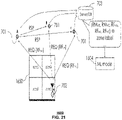
- FIG. 28 depicts an illustrative embodiment of a method for determining location information and uses thereof in accordance with various aspects described herein.
- the subject disclosure describes, among other things, illustrative embodiments for determining location information for mobile devices utilizing anchors and RF channel characteristics.
- information e.g, calculated locations, RF channel characteristic(s) of messages, radio measurements, and so forth
- information can be collected from a real time location system which utilizes instantaneous radio measurements of messages communicated in the system for location determination, such as described with respect to FIGS. 1-11 .
- an RF fingerprint(s) e.g., RF signature(s)
- the RF fingerprint can be based on an RF fingerprint model generated in a number of ways, such as via machine learning.
- the RF fingerprint model can also be based on other data for the various locations, such as instantaneous radio measurements. Other embodiments are described in the subject disclosure.
- FIG. 1 is a block diagram illustrating an exemplary, non-limiting embodiment of a mobile tag 101 and anchors 102 (“A”) and 104 (“B”) for determining location information between the mobile tag 101 (“M”) and the anchors 102 and 104 in accordance with various aspects described herein.
- the devices and functions described with respect to FIG. 1 which can include messaging for performing location determination, can also be utilized in generating an RF fingerprint model(s) for a demarcated area according to RF channel characteristics, calculated locations and/or other collected data so that location determination can be performed according to the RF fingerprint model(s).
- anchor 102 can be configured to transmit a first wireless signal (s 1 ) that can be received by anchor 104 and the mobile tag 101 .
- the timing of transmission by anchor 102 and reception by the mobile tag 101 and anchor 104 of the first wireless signal (s 1 ) is depicted in FIG. 2 .
- anchor 102 transmits the first wireless signal (s 1 ) at time t 0 , which in turn is received by the mobile tag 101 at time t 1 and anchor 104 at time t 2 .
- Anchor 104 can be configured to transmit a second wireless signal (s 2 ) at time t 3 , which is received by the mobile tag 101 at time t 4 .
- the mobile tag 101 can be configured to use a time difference of arrival (TDOA) measurement technique based on the first and second wireless signals (s 1 , s 2 ) to determine location information between the mobile tag 101 and the anchors 102 and 104 as will be described below.
- TDOA time difference of arrival
- d AB is a constant known to the mobile tag 101 and the time variables of the factor c(t 4 ⁇ t 1 ⁇ t) are also known to the mobile tag 101
- d AM ⁇ square root over (( x ⁇ x 1 ) 2 +( y ⁇ y 1 ) 2 ) ⁇ ,
- d BM ⁇ square root over (( x ⁇ x 2 ) 2 +( y ⁇ y 2 ) 2 ) ⁇ .
- Equation EQ 6 has only two unknown variables (x, y) that can be solved by the mobile tag 101 utilizing a non-linear regression technique (e.g., Nonlinear Least Squares).
- a non-linear regression technique e.g., Nonlinear Least Squares
- Such a technique produces a hyperbolic curve of solutions for x and y that is associated with the positions of anchors pairs 102 , 104 .
- the mobile tag 101 can be further configured to perform the above calculation across other anchor pairs as depicted in FIG.
- the devices and functions described with respect to FIG. 3 which can include messaging for performing location determination, can also be utilized in generating an RF fingerprint model(s) for a demarcated area according to RF channel characteristics, calculated locations and/or other collected data so that location determination can be performed according to the RF fingerprint model(s).
- the intersection 109 of hyperbolic curves h AB , h AC and h CD corresponding to equations EQ 7A-7C can provide a two-dimensional coordinate location (i.e., x, y) for the mobile tag 101 relative to anchors pairs 102 and 104 (anchors A/B), 106 and 108 (anchors A/C), 106 and 108 (anchors C/D). It will be appreciated that the mobile tag 101 can also be configured to determine a three-dimensional coordinate (i.e., x, y, z) of its location in a number of different ways including by utilizing a fourth pair of anchors.
- the pairs of anchors utilized by the mobile tag 101 must satisfy a coverage area that encompasses the anchor pairs and the mobile tag 101 .
- the coverage area of anchor 102 (anchor “A”) is defined by reference 110
- the coverage area of anchor 104 (anchor “B”) is defined by reference 112 .
- the overlapping region 114 represents the coverage area that is jointly shared by anchors 102 and 104 . Since anchor 104 and the mobile tag 101 must be able to receive the first wireless signal (s 1 ) generated by anchor 102 , anchors 104 and the mobile tag 101 must be located in the overlapping region 114 .
- the mobile tag 101 must be in the overlapping region 114 in order to receive the second wireless signal (s 2 ) generated by anchor 104 .
- Conditions such as described above for anchor pairs 102 , 104 (anchors A/B) must also be satisfied by the other anchor pairs 102 , 106 (anchors A/C) and anchor pairs 106 , 108 (anchors C/D) in order to enable the mobile tag 101 to perform the triangulation calculations described above for hyperbolic curves h AB , h AC and h CD .
- FIG. 4B shows that the coverage areas 110 and 116 of anchor pairs 102 , 106 (anchors A/C), respectively, creates an overlapping region 120 that encompasses anchors 102 and 106 and the mobile tag 101 , thereby enabling the mobile tag 101 to calculate hyperbolic curve h AC .
- FIG. 4C shows that the coverage areas 122 and 124 of anchor pairs 106 , 108 (anchors C/D), respectively, creates an overlapping region 126 that encompasses anchors 106 and 108 and the mobile tag 101 , thereby enabling the mobile tag 101 to calculate hyperbolic curve h CD .
- FIG. 5 depicts another embodiment for determining location information between the mobile tag 101 and an anchor 102 .
- the devices and functions described with respect to FIG. 5 which can include messaging for performing location determination, can also be utilized in generating an RF fingerprint model(s) for a demarcated area according to RF channel characteristics, calculated locations and/or other collected data so that location determination can be performed according to the RF fingerprint model(s).
- the mobile tag 101 can be configured to use a two-way time of arrival (TW-TOA) process for determining a distance between itself and the anchor 102 .
- TW-TOA time of arrival
- the process may begin at anchor 102 which transmits a first wireless signal (s 1 ), which is received at time t 1 .
- Wireless signal (s 1 ) can include the x-y coordinates (x 1 , y 1 ) of anchor 102 .
- the mobile tag 101 Upon receiving the first wireless signal (s 1 ), the mobile tag 101 can be configured to transmit a second wireless signal (s 2 ), which can represent a range request (R-REQ) signal directed to anchor 102 initiated at time t 2 and received by anchor 102 at time t 3 .
- R-REQ range request
- the anchor 102 Upon receiving the R-REQ signal at time t 3 , the anchor 102 can process the R-REQ signal and initiate at time t 4 a transmission of a third wireless signal (s 3 ) representing a range response (R-RSP) signal that is received by the mobile tag 101 at time t 5 .
- Anchor 102 can be configured to transmit the value of ⁇ t in the R-RSP signal for use by the mobile tag 101 in calculating d r-trip .
- the processing time to receive the R-REQ signal and respond with the transmission of the R-RSP signal can be a fixed processing time interval known and used by all devices in a network performing TW-TOA analysis.
- the R-REQ and the R-RSP signals can be transmitted using ultra-wideband signaling technology to increase the accuracy of the d r-trip calculations.
- the TW-TOA illustrated in FIG. 5 can be used by either the mobile tag 101 or anchors in other embodiments to calculate a relative distance between each other.
- TW-TOA process described above can also between mobile tags 101 . That is, anchor 102 shown in FIG. 5 can be replaced with another mobile tag 101 . In this embodiment, mobile tags 101 can use TW-TOA to measure a distance between each other.
- FIGS. 1-3, 4A-4C, and 5-6 can be adapted so that the anchors are replaced with mobile tags 101 .
- mobile tags 101 can use TDOA or TW-TOA to obtain location information amongst each other based on the processes described earlier for TDOA and TW-TOA, respectively.
- a mobile tag 101 can be configured with multiple antennas and phase detectors to calculate an angle of arrival of any wireless signal generated by an anchor and received by the mobile tag 101 based on a phase difference between the antennas determined from the received wireless signal.
- An angle of arrival calculation can be used to determine an angular orientation between a mobile tag 101 and an anchor.
- the mobile tags 101 can be configured to determine a speed of travel of the mobile tag 101 by performing multiple location measurements over a time period. With angular orientation and speed of travel, a mobile tag 101 can also determine its trajectory of travel.
- the mobile tags 101 can be configured with an orientation sensor (e.g., a magnetometer) to determine an angular orientation with an anchor.
- TDOA, TW-TOA, angular orientation, speed of travel, or combinations thereof can be utilized in an environment such as illustrated in FIG. 7 .
- the devices and functions described with respect to FIG. 7 which can include messaging for performing location determination, can also be utilized in generating an RF fingerprint model(s) for a demarcated area according to RF channel characteristics, calculated locations and/or other collected data so that location determination can be performed according to the RF fingerprint model(s).
- FIG. 7 is a block diagram illustrating an exemplary, non-limiting embodiment for determining location information of mobile tags 201 in a demarcated area 200 in accordance with various aspects described herein.
- the demarcated area 200 can represent a warehouse with racks or shelves 206 for managing the distribution of products and/or materials. It will be appreciated that the demarcated area 200 can correspond to numerous other use cases, including without limitation, a parking lot for managing parking spots, a commercial or retail environment for monitoring individuals and/or assets, assisted navigation of vehicles and/or machinery such as robots or forklifts, collision detection and avoidance of objects, managing separation between objects and/or individuals, as well as other suitable applications for which the subject disclosure can be applied to.
- the demarcated area 200 of FIG. 7 will be considered a warehouse with racks and/or shelves 206 .
- the measurement technique used by the mobile tags 201 to determine location information within the demarcated area 200 can depend on the location of the mobile tags 201 relative to other anchors 204 in the demarcated area 200 .
- the mobile tag 201 can be configured to perform TDOA measurements among pairs of anchors 204 as described above in relation to FIGS. 1, 2, 3, 4A, 4B, 4C .
- the mobile tag 201 when the mobile tag 201 is located in an aisle 203 between racks/shelves 206 , the mobile tag 201 can be configured to perform TW-TOA measurements among one or more anchors 204 located in the aisle 203 as described above in relation to FIGS. 5-6 .
- an aisle 203 can be configured with two or more anchors 204 .
- An aisle 203 can have more than two anchors 204 when the coverage area of a first anchor 204 at one end of the aisle 203 has insufficient coverage to reach a second anchor 204 at the other end of the aisle 203 and vice-versa—see sections 220 and 224 .
- the coverage area of a first anchor 204 at one end of the aisle 203 has sufficient coverage to reach a second anchor 204 at the end of the aisle 203 and vice-versa, then no more than two anchors 204 is necessary in the aisle 203 —see region 222 .
- FIG. 8 depicts an illustrative embodiment of a method 300 in accordance with various aspects described herein.
- the devices and functions described with respect to FIG. 8 which can include messaging for performing location determination, can also be utilized in generating an RF fingerprint model(s) for a demarcated area according to RF channel characteristics, calculated locations and/or other collected data so that location determination can be performed according to the RF fingerprint model(s).
- Method 300 can begin at step 302 where a computing system such as a server (described below in relation to FIG. 11 ) is configured to identify anchor pairs in the demarcated area 200 of FIG. 7 that provide sufficient coverage to enable TW-TOA or TDOA measurements depending on the location of the mobile tags 201 .
- a computing system such as a server (described below in relation to FIG. 11 ) is configured to identify anchor pairs in the demarcated area 200 of FIG. 7 that provide sufficient coverage to enable TW-TOA or TDOA measurements depending on the location of the mobile tags 201 .
- mobile tags 201 are configured to use TDOA measurement techniques to determine location information.
- the server is configured at step 302 to identify, for a certain number of x-y coordinates obtained from a digitization of an open space defined by region 212 where a mobile tag 201 may be located, at least three pairs of anchors 204 that have overlapping coverage that satisfy the condition described earlier in relation to FIGS. 3, 4A, 4B and 4C . It will be appreciated that other techniques other than digitization of an open space can be used to identify possible x-y coordinates used by the server to perform step 302 .
- mobile tags 201 are configured to use TW-TOA measurement techniques to determine location information.
- the server is configured at step 302 to identify at least two anchors 204 covering at least a portion of the aisle 203 .
- the mobile tags 201 can be configured to perform TW-TOA with anchors 204 at opposite ends of an aisle 203 to provide further accuracy or at least validate location information determined by the mobile tag 201 .
- pairs of anchors 204 can be located at opposite ends of an aisle 203 , or in between aisles 203 when a pair of anchors 204 is unable to cover for the full-length of an aisle 203 .
- the mobile tag 201 can be configured to perform TW-TOA measurement according to the embodiments described above in relation to FIGS. 5-6 .
- a server can be configured at step 302 to determine optimal pairs of anchors 204 in FIG. 7 that provide sufficient coverage for any mobile tag 201 in the area such as region 212 to perform triangulation with at least three pairs of anchors 204 that satisfy the conditions set forth in FIGS. 4A-4C .
- the process of selecting anchor pairs for TDOA triangulation and optimal coverage in open spaces defined by region 212 can be performed as an iterative analysis by a server at step 302 , or by other techniques that enable convergence to a solution that provides coverage to mobile tags 201 across most (if not all) open spaces depicted by region 212 .
- the server can identify the anchor pairs 204 in the aisles 203 that provide sufficient coverage to cover the aisle from end-to-end as illustrated by sections 220 - 224 of FIG. 7 .
- the server can proceed to step 304 to identify a schedule for communications between anchor pairs 204 and one or more mobile tags 201 .
- the anchors 204 can be configured to transmit and receive wireless signals in a single frequency band.
- a single frequency band for performing TDOA or TW-TOA measurements can reduce the design complexity of mobile tags 201 and corresponding costs.
- the server can be configured to utilize a time-division scheme (timeslots) such as shown in FIG. 9 to enable anchor pairs 204 to communicate with each other and with one or more mobile tags 201 without causing signal interference (i.e., wireless collisions).
- the server can be configured, for example, to determine at step 304 which anchor pairs 204 have overlapping coverage areas with other anchor pairs and schedule the communications between the anchor pairs and the mobile tags 201 during specific timeslots T 0 ⁇ T n (e.g., 402 a through 402 n ).
- the server can schedule simultaneous wireless communications of both anchor pairs 204 during a same timeslot (not shown in FIG. 9 ).
- the server can be further configured at step 304 to determine which of the anchor pairs 204 will initiate/start a measurement session through a transmission of wireless signal (s 1 ).
- Such anchors 204 will be referred to herein as source anchors 204 .
- the anchor pairs 204 identified by the server at step 302 , and the transmission schedule and source anchors 204 determined by the server at step 304 can be communicated to all anchors 204 via gateway anchors 208 communicatively coupled to the server.
- Gateway anchors 204 can be located at the edges of the demarcated area 200 or in other locations of the demarcated area 200 .
- the server can also be configured to share the identification of the anchor pairs 204 and transmission schedules with the mobile tags 201 . This information can be conveyed by gateway anchors 208 when the mobile tags 201 are in close vicinity thereto, or by way of other anchors 204 which can be configured to obtain this information from the gateway anchors 208 and relay the information to the mobile tags 201 .
- the locations of the anchors 204 in FIG. 7 can be predefined before the implementation of step 302 by the server. That is, the anchors 204 can be placed by one or more individuals managing the placement of shelves/racks, etc. in the demarcated area 200 . The specific x-y coordinate locations of the anchors 204 can be determined by such individuals and communicated to the server via, for example, a look-up table provided to the server, in order to perform step 302 .
- the location of anchors can instead be determined by the server at step 302 .
- the server can be provided with the location of racks/shelves and/or other objects in the demarcated area 200 along with dimensions of the demarcated area 200 and dimensions of the racks/shelves and/or other objects.
- the server can then be configured to perform an iterative analysis to determine a location for anchors 204 relative to the racks/shelves identified to the server that provide desirable coverage for mobile tags 201 to perform TDOA analysis in open spaces or TW-TOA analysis in aisles 203 .
- the server can be configured to report the x-y coordinate locations of anchors 204 to one or more personnel managing the floor space of the demarcated area 200 for placement of the anchors 204 in their corresponding x-y coordinate locations.
- the server can be configured to provide the x-y coordinates to all anchors 204 in the demarcated area 200 via gateway anchors 208 as described above.
- This information can also be conveyed by gateway anchors 208 when the mobile tags 201 are in close vicinity thereto, or by way of other anchors 204 which can be configured to obtain this information from the gateway anchors 208 and relay the information to the mobile tags 201 .
- mobile tags 201 can be configured to initiate a process using TDOA or TW-TOA (and in some instances angular orientation measurements) to obtain location information depending on the location of the mobile tag 201 in the demarcated area 200 .
- the source anchors 204 can be configured to transmit in the first wireless signal (s 1 ) an indication whether to use TDOA or TW-TOA.
- the indication may be a flag or message that enables the mobile tag 201 to determine whether it is in region 212 (an open space) or region 214 (an aisle 203 ).
- the first wireless signal (s 1 ) can also convey to the mobile tag 201 the x-y coordinates of one or both anchor pairs 204 .
- the mobile tags 201 can be configured with a look-up table that includes the x-y coordinates of all anchors 204 in the demarcated area 200 .
- the mobile tags 201 can obtain the lookup-table from the server via the gateway anchors 208 or during provisioning of the mobile tag 201 by a user before the mobile tag 201 is deployed for use in the demarcated area 200 .
- step 306 can be adapted to enable mobile tags 101 to measure and thereby obtain location information between each other using TDOA or TW-TOA as described earlier in relation to FIGS. 1-3, 4A-4C, and 5-6 .
- a mobile tag 201 calculates location information via TDOA or TW-TOA measurement techniques
- the mobile tag 201 can in turn report at step 308 the location information to other devices such as other mobile tags 201 , the anchors 204 in its coverage area, and/or the server by communicating directly to one or more gateway anchors 208 or indirectly via one or more intermediate anchors 204 that can communicate with the one or more gateway anchors 208 .
- the location information can include without limitation, x-y coordinates of the mobile tag 201 within the demarcated area 200 , a speed of travel of the mobile tag 201 determined from multiple location measurements over a time period, a trajectory of the mobile tag 201 , angular orientation of the mobile tag 201 relative to other anchors 204 and/or other mobile tags 201 , or any combinations thereof. Since sharing location information does not require precision measurements via ultra-wideband signals, the mobile tags 201 can be configured to share location information with other devices using lower power wireless signaling techniques such as Bluetooth®, ZigBee®, WiFi or other suitable wireless signaling protocols.
- Sharing location information of the mobile tags 201 enables the server and/or other devices such as the anchors 204 and other mobile tags 201 to track at step 310 movement and location of the mobile tags 201 and detect and perform mitigation procedures at step 312 .
- mobile tags 201 can be configured to detect issues such as proximity violations and/or possible collisions between mobile tags 201 from this shared information. Upon detecting such issues, the mobile tags 201 can be configured to assert an alarm (audible and/or visual) and/or take further mitigation action such as slow down or otherwise disable a vehicle (e.g., a forklift, robot, automobile, etc.) that may collide with an individual carrying a mobile tag 201 .
- a vehicle e.g., a forklift, robot, automobile, etc.
- the mobile tag 201 may be integrated in an identification badge or embedded in a mobile communication device (e.g., mobile phone, tablet, etc.), clipped on a shirt, integrated into an article of clothing of the individual or otherwise carried by the individual via other suitable methods for carrying the mobile tag 201 .
- a mobile communication device e.g., mobile phone, tablet, etc.
- a mobile tag 201 can be adapted to obtain location information based on a determination whether it is in an open space defined by region 212 or an aisle 203 defined by region 214 .
- a mobile tag 201 can receive wireless signals from both an anchor 204 in an open space and an anchor 204 in an aisle 203 .
- the mobile tag 201 can be configured to obtain from its internal memory a history of locations in the demarcated area 200 that are stored by the mobile tag 201 to determine if the most recent location (or trajectory of the mobile tag 201 ) places the mobile tag 201 in an open space, region 212 , or aisle 203 , region 214 .
- the mobile tag 201 determines it is likely in an open space, region 212 , it can proceed to perform TDOA analysis based on the wireless signals generated by anchor pairs 204 in the open space. Otherwise, if the mobile tag 201 determines it is likely in an aisle, region 214 , it can proceed to perform TW-TOA analysis based on the wireless signals generated by anchor pairs 204 in the aisle 203 . If the mobile tag 201 is unable to make a determination where it is likely located from a history of locations, the mobile tag 201 can be configured to perform TDOA analysis based on the wireless signals generated by anchor pairs 204 in the open space and TW-TOA analysis based on the wireless signals generated by anchor pairs 204 in the aisle 203 . The mobile tag 201 can be configured to compare the location determined from TDOA and the location determined from TW-TOA to the stored location history and thereby make a determination as to which location to choose that more closely mimics the location history of the mobile tag 201 .
- FIG. 10 is a block diagram of an example, non-limiting embodiments of a communication device 500 in accordance with various aspects described herein.
- Communication device 500 can serve in whole or in part as an illustrative embodiment of a mobile tag 101 and an anchor 102 , 104 , 106 , 108 , 204 as depicted in FIGS. 1-7 , and can be configured to perform portions of method 300 of FIG. 8 .
- the devices and functions described with respect to FIG. 10 which can include messaging for performing location determination, can also be utilized in generating an RF fingerprint model(s) for a demarcated area according to RF channel characteristics, calculated locations and/or other collected data so that location determination can be performed according to the RF fingerprint model(s).
- communication device 500 can comprise a first wireless transceivers 501 , a user interface (UI) 504 , a power supply 514 , and a processing system 506 for managing operations of the communication device 500 .
- communication device 500 can further include a second wireless transceiver 502 , a motion sensor 518 , and an orientation sensor 520 .
- the first wireless transceiver 501 can be configured to support wideband wireless signals such as ultra-wideband signals (e.g., 500 MHz) for performing precision measurements such as TDOA and TW-TOA as described above and can be further configured for exchanging messages (e.g., x-y coordinates, location flags, etc.).
- the second wireless transceiver 502 can be configured to support wireless access technologies such as Bluetooth®, ZigBee®, or WiFi (Bluetooth® and ZigBee® are trademarks registered by the Bluetooth® Special Interest Group and the ZigBee® Alliance, respectively).
- the second wireless transceiver 502 can be utilized to conserve power and offload messaging between communication devices by utilizing narrow band signals such as Bluetooth®, ZigBee®, or WiFi, instead of ultra-wideband signals.
- One or both wireless transceivers 501 , 502 can also be used for obtaining a strength indicator (RSSI).
- RSSI strength indicator
- One or both wireless transceivers 501 , 502 can also be equipped with multiple antennas and one or more phase detectors to determine angle of arrival of wireless signals and thereby an orientation of the communication device 500 (e.g., mobile tag 101 ) relative to another communication device 500 (e.g., anchor 204 ).
- the communication device 500 e.g., mobile tag 101
- another communication device 500 e.g., anchor 204
- the UI 504 can include an input device 508 that provides at least one of one or more depressible buttons, a tactile keypad, a touch-sensitive keypad, or a navigation mechanism such as a roller ball, a joystick, or a navigation disk for manipulating operations of the communication device 500 .
- the input device 508 can be an integral part of a housing assembly of the communication device 500 or an independent device operably coupled thereto by a tethered wireline interface (such as a USB cable) or a wireless interface supporting for example Bluetooth®.
- the UI 504 can further include a presentation device 510 .
- the presentation device 510 can include a vibrator to generate haptic feedback, an LED (Light Emitting Diode) configurable by the processing system 506 to emit one or more colors, and/or a monochrome or color LCD (Liquid Crystal Display) or OLED (Organic LED) display configurable by the processing system to present alphanumeric characters, icons or other displayable objects.
- a vibrator to generate haptic feedback
- an LED Light Emitting Diode
- LCD Liquid Crystal Display
- OLED Organic LED
- the UI 504 can also include an audio system 512 that utilizes audio technology for conveying low volume audio (for proximity listening by a user) and/or high volume audio (for hands free operation).
- the audio system 512 can further include a microphone for receiving audible signals of an end user.
- the audio system 512 can also be used for voice recognition applications.
- the UI 504 can further include an image sensor 513 such as a charged coupled device (CCD) camera for capturing still or moving images in a vicinity of the communication device 500 .
- the camera can be used for performing facial recognition and user ID recognition that can be combined with embodiments of the subject disclosure.
- CCD charged coupled device
- the power supply 514 can utilize common power management technologies such as replaceable and rechargeable batteries, supply regulation technologies, and/or charging system technologies for supplying energy to the components of the communication device 500 to facilitate portable applications.
- the charging system can utilize external power sources such as DC power supplied over a physical interface such as a USB port or other suitable tethering technologies.
- the motion sensor 518 can utilize motion sensing technology such as an accelerometer, a gyroscope, or other suitable motion sensing technology to detect motion of the communication device 500 in three-dimensional space.
- the orientation sensor 520 can utilize orientation sensing technology such as a magnetometer to detect the orientation of the communication device 500 (in degrees, minutes, or other suitable orientation metrics).
- the orientation sensor 520 can replace a need for utilizing multiple antennas with the first and/or second wireless transceivers 501 , 502 and a phase detector for performing angle of arrival measurements.
- the function of the orientation sensor 520 can be combined with an angle of arrival measurement performed with multiple antennas with the first and/or second wireless transceivers 501 , 502 and a phase detector.
- the processing system 506 can utilize computing technologies such as a microprocessor, a digital signal processor (DSP), programmable gate arrays, application specific integrated circuits (ASICs), and/or a video processor with associated storage memory such as Flash, ROM, RAM, SRAM, DRAM or other storage technologies for executing computer instructions, controlling, and processing data supplied by the aforementioned components of the communication device 500 .
- computing technologies such as a microprocessor, a digital signal processor (DSP), programmable gate arrays, application specific integrated circuits (ASICs), and/or a video processor with associated storage memory such as Flash, ROM, RAM, SRAM, DRAM or other storage technologies for executing computer instructions, controlling, and processing data supplied by the aforementioned components of the communication device 500 .
- the communication device 500 can include a reset button (not shown).
- the reset button can be used to reset the controller 506 of the communication device 500 .
- the communication device 500 can also include a factory default setting button positioned, for example, below a small hole in a housing assembly of the communication device 500 to force the communication device 500 to re-establish factory settings.
- the communication device 500 as described herein can operate with more or less of the circuit components shown in FIG. 10 . These variant embodiments can be used in one or more embodiments of the subject disclosure.
- FIG. 11 depicts an exemplary diagrammatic representation of a machine in the form of a computing system 600 within which a set of instructions, when executed, may cause the machine to perform any one or more of the methods described above.
- One or more instances of the machine can operate, for example, as the computing system referred to in method 300 of FIG. 8 .
- the components and functions described with respect to FIG. 11 which can include messaging for performing location determination, can also be utilized in generating an RF fingerprint model(s) for a demarcated area according to RF channel characteristics, calculated locations and/or other collected data so that location determination can be performed according to the RF fingerprint model(s).
- the machine may be connected (e.g., using a network 626 ) to other machines. In a networked deployment, the machine may operate in the capacity of a server or a client user machine in a server-client user network environment, or as a peer machine in a peer-to-peer (or distributed) network environment.
- the machine may comprise a server computer, a client user computer, a personal computer (PC), a tablet, a smart phone, a laptop computer, a desktop computer, a control system, a network router, switch or bridge, or any machine capable of executing a set of instructions (sequential or otherwise) that specify actions to be taken by that machine.
- a communication device of the subject disclosure includes broadly any electronic device that provides data communication.
- the term “machine” shall also be taken to include any collection of machines (physical or virtual machines) that individually or jointly execute a set (or multiple sets) of instructions to perform any one or more of the methods discussed herein.
- the computer system 600 may include a processor (or controller) 602 (e.g., a central processing unit (CPU)), a graphics processing unit (GPU, or both), a main memory 604 and a static memory 606 , which communicate with each other via a bus 608 .
- the computer system 600 may further include a display unit 610 (e.g., a liquid crystal display (LCD), a flat panel, or a solid state display).
- the computer system 600 may include an input device 612 (e.g., a keyboard), a cursor control device 614 (e.g., a mouse), a disk drive unit 616 , a signal generation device 618 (e.g., a speaker or remote control) and a network interface device 620 .
- the embodiments described in the subject disclosure can be adapted to utilize multiple display units 610 controlled by two or more computer systems 600 .
- presentations described by the subject disclosure may in part be shown in a first of the display units 610 , while the remaining portion is presented in a second of the display units 610 .
- the disk drive unit 616 may include a tangible computer-readable storage medium 622 on which is stored one or more sets of instructions (e.g., software 624 ) embodying any one or more of the methods or functions described herein, including those methods illustrated above.
- the instructions 624 may also reside, completely or at least partially, within the main memory 604 , the static memory 606 , and/or within the processor 602 during execution thereof by the computer system 600 .
- the main memory 604 and the processor 602 also may constitute tangible computer-readable storage media.
- an RF fingerprint(s) (e.g., RF signature(s)) can be generated that describes, or is otherwise indicative of, one or more RF channel characteristics for positions or zones within a particular area (e.g., factory, storage facility, outdoor venue, indoor venue, or other areas where location determinations can be employed), such as a demarcated area associated with a plurality of anchors.
- the RF fingerprint can be an RF fingerprint model generated from machine learning according to observed RF characteristics of RF channels for various mobile devices or objects at various positions (or various zones) within the particular area.
- the RF fingerprint can be an RF fingerprint mapping generated by various techniques (which may or may not include machine learning) according to observed RF characteristics of RF channels for various mobile devices or objects at various positions or zones within the particular area.
- the RF fingerprint model can be based on one or multiple RF characteristics of the channels at various locations.
- the RF fingerprint can also be based on other data for the various locations, such as instantaneous radio measurements. For any unique location within the area, there is a vector of values representing the RF characteristics (or combination of different RF characteristics such as Receiving Signal Strength (RSS) and Channel Impulse Response (CIR) of the channel between the object and the particular anchors.
- RSS Receiving Signal Strength
- CIR Channel Impulse Response
- the RF fingerprint at location X can be (obj_type, RF_cha1, RF_cha2, . . . , RF_cha9) where a single RF characteristic (e.g., RSS or CIR) is being collected.
- a single RF characteristic e.g., RSS or CIR
- information can be collected from a real time location system (by one or more devices that are part of and/or distinct from the real time location system), where the real time location system determines device or object positions based on instantaneous radio measurements from, or otherwise associated with, the radio object.
- the real time location system can manage one or more radio or range measurement locating processes, such as described with respect to FIGS. 1-11 . These described radio or range measurement locating processes and devices (or functions or components thereof) can be utilized (in whole or in part) in conjunction with one or more of the embodiments described herein and/or in place of one or more functions or components described with respect to the one or more of the embodiments.
- the collected information can include RF channel characteristic(s) (e.g., RSS, CIR, and so forth) for messages that are wirelessly communicated within the real time location system in conjunction with location determinations for the mobile devices or objects.
- the wireless messages can be range requests and/or range responses (e.g., transmitted from mobile device(s) to anchor(s), transmitted from anchor(s) to mobile device(s), and/or transmitted from anchor(s) to anchor(s)) that are utilized by the real time location system to obtain instantaneous radio measurements.
- the messages that are being analyzed to identify the RF channel characteristics for a particular location can be other types of messages (e.g., transmitted from mobile device(s) to anchor(s), transmitted from anchor(s) to mobile device(s), and/or transmitted from anchor(s) to anchor(s)) other than range requests and/or range responses.
- the messages that are being analyzed to identify the RF channel characteristics for a particular location can be a combination of range requests, range responses and/or other types of messages (e.g., transmitted from mobile device(s) to anchor(s), transmitted from anchor(s) to mobile device(s), and/or transmitted from anchor(s) to anchor(s)).
- the collected information can also include the radio measurements (e.g., range measurements) which are being used by the real time location system to calculate object locations by way of various geometric position methods (e.g., TDOA, TOA, and so forth) or other radio measurement locating processes.
- radio measurements e.g., range measurements
- TDOA TDOA
- TOA TOA
- other radio measurement locating processes e.g., TDOA, TOA, and so forth
- radio or range measurement locating processes and devices that are utilized in such processes are described with respect to U.S. Pat. No. 10,408,917 filed Jan. 11, 2019; U.S. Pat. No. 10,444,321 filed Dec. 31, 2014; and U.S. Patent Application Publication 2015/0156746 filed Dec. 3, 2014, the disclosures of all of which are incorporated by reference herein in their entirety.
- These described radio or range measurement locating processes and devices can be utilized (in whole or in part) in conjunction with one or more of the embodiments described herein and/or in place of one or more functions or components described with respect to the one or more of the embodiments.
- the labeled data set can correspond to the anchors that are servicing the particular area and the RF channels representing wireless transmissions to or from the anchors and/or to or from the mobile devices at particular device locations.
- multiple RF characteristics can form the data sample, such as utilizing both RSS and CIR for each of the locations.
- the data sample may or may not include other data, such as the instantaneous radio measurements for the location.
- the trained RF fingerprint model can be utilized to identify a position or zone when RF characteristics for communications associated with a mobile device or object in the demarcated area are received.
- the trained RF fingerprint model can be used to generate new positions when new RF data is available.
- the trained RF fingerprint model can be used to improve position accuracy determinations, such as by allowing for a comparison of position determinations from a radio measurement technique as compared to position determinations from the RF fingerprint model.
- the trained RF fingerprint model can provide a position determination when there are no sufficient instantaneous radio measurements for a mobile device or object that would allow for a position calculation by a radio or range measurement technique.
- the RF characteristics for the messages being communicated during the radio measurement locating processes can be collected (along with the calculated position of the mobile device) so that a site survey for RF channel characteristics of the entire area does not need to be performed.
- a site survey (of the entire area or portion(s) thereof) for RF channel characteristics can be performed and the survey RF data can be utilized in conjunction with other collected data (e.g., the RF channel characteristics collected from the messages) or other functions described herein.
- the survey RF data can be compared to the RF channel characteristics collected from the messages to evaluate accuracy.
- differences in the RF survey data and the RF channel characteristics collected from the messages can be monitored to determine potential changes to the area (e.g., a change in area layout (such as a shelf being added, removed or moved), an anchor adjustment (such as an anchor being added, removed or moved), and so forth).
- a change in area layout such as a shelf being added, removed or moved
- an anchor adjustment such as an anchor being added, removed or moved
- the interested metric e.g., zone
- the use of zones allows for less resolution in determining positions.
- One or more embodiments can utilize various machine learning based on the training data described herein.
- the RF data being collected characterizes the channel condition of the RF signal path between the mobile device or object and each one of the plurality of anchors (which are available for communication).
- the machine learning also allows the radio or range measurement calculations (e.g., TDOA, TOA, and so forth) to be combined with the RF data as an extended feature set for the learning model. For instance, if the label is the calculated position (e.g., from TDOA, TOA, and so forth), the learning problem can be a regression problem.
- the learning problem can be a classification problem.
- Various machine learning algorithms can be utilized for regression or classification, and can be used in building the machine learning model, such as one or any combination of support vector machines, neural networks, K-nearest neighbors, gradient boosting, and so forth.
- radio measurement locating processes and combinations of processes can be utilized which facilitate the generating of the RF fingerprint model.
- the radio measurement locating processes can also be in the uplink and/or downlink.
- the machine learning based method described herein can collect the RF characteristic data (for mobile device or object locations) at the anchors.
- analysis and computation of the training data can be done at a server in communication with all or some of the anchors (e.g., each anchor can directly send the data samples to the server and/or particular anchor(s) can send the data samples to other anchor(s) which can then directly send the data samples to the server).
- the server can have the computation power required for running a more complicated machine learning algorithm and more storage space for more data samples to be used in training the model, as compared to one of the mobile devices.
- This example in the uplink can also provide for less complexity and power consumption within the network (e.g., by anchors and/or by mobile device or objects).
- only one model may be maintained (or only one model for each type of mobile device or object (e.g., mobile personal tag, forklift radio, mobile phone, and so forth).
- one model per mobile device or object may be maintained.
- one model per mobile device or object may be maintained in downlink cases. As described herein, any number of models can be maintained and they can be stored at a single device or multiple devices.
- FIG. 12 is a block diagram of a portion of a system 700 illustrating an exemplary, non-limiting embodiment of a mobile device 702 (labeled “M”) and stationary anchors 701 (anchors labeled “A”, “B”, “C”) for determining location information between the mobile device 702 and the stationary anchors 701 in accordance with various aspects described herein.
- System 700 shows three anchors 701 that facilitate determining the position of mobile device 702 , although any number of anchors in various configurations and layouts can be utilized, such as shown in FIG. 7 .
- more than three anchors can be utilized in order to provide a more robust RF fingerprint for device or object locations in a demarcated area that is serviced by the more than three anchors.
- the anchors 701 can be various types of stationary devices that are capable of wireless communication and whose position information is known (e.g., x-y coordinates and the distance between anchors).
- the anchors 701 can be one or more of the anchors as described herein with respect to FIGS. 1-11 .
- System 700 shows one mobile device or object 702 , although any number of mobile devices can be utilized, such as shown in FIG. 7 .
- the mobile device 702 can be various types of mobile devices that are capable of wireless communication, such as a mobile tag, mobile phone, equipment radio, vehicle radio, and so forth.
- the mobile device 702 can be one or more of the mobile tags or mobile objects as described herein with respect to FIGS. 1-11 .
- System 700 utilizes uplink TDOA as a radio measurement locating process for determining mobile device locations within a demarcated area.
- position learning can be employed based on RF channel characteristics of messages utilized during the uplink TDOA processes.
- the anchors 701 can collect RF characteristics RF MA , RF MB , RF MC from received REQ messages from the mobile device 702 .
- the REQ messages and the RSP messages are utilized by system 700 to perform the uplink TDOA process for calculating the location of the mobile device 702 .
- the anchors 701 can transmit the data samples, which include the RF channel characteristics corresponding to the particular location, to a server 703 .
- the RF characteristics can be various types or combinations such as RSS and/or CIR.
- the server 703 can utilize the radio measurements that are generated as a result of communication of the REQ messages and the RSP messages to perform the uplink TDOA calculation which calculates a location of the mobile device 702 .
- the server 703 can form a training set from the RF channel characteristics and the corresponding calculated locations.
- the server 703 can then train a machine learning model(s) 704 which can learn an RF fingerprint of the demarcated area.
- Various machine learning algorithms can be utilized in building the machine learning model 704 , such as support vector machines, neural networks, K-nearest neighbors, gradient boosting, other regression analysis, and so forth. In one embodiment, only one RF fingerprint model 704 is maintained for the demarcated area.
- only one RF fingerprint model 704 for each type of mobile device or object is maintained for the demarcated area.
- one RF fingerprint model 704 per mobile device or object is maintained for the demarcated area.
- the RF fingerprint model 704 is generated, new RF channel characteristics that are determined for the mobile device 702 (from the new REQ messages received by the anchors 701 as described above) can then be utilized in conjunction with the RF fingerprint model 704 to determine a location of the mobile device 702 .
- the location determined from the RF fingerprint model 704 e.g., RF-based location
- the uplink TDOA process e.g., range measurement (RM)-based location by the server 703
- the comparison of the RF-based location and the RM-based location can be utilized for providing accuracy scores for one or both of the RF-based location determination and the RM-based location calculation.
- the RF fingerprint model 704 can be adjusted according to subsequent location determinations, such as increasing the resolution of the location determinations via the RF fingerprint model by providing a more robust training data set.
- FIG. 13 is a block diagram of a portion of a system 800 illustrating an exemplary, non-limiting embodiment of the mobile device 702 and the stationary anchors 701 in accordance with various aspects described herein.
- System 800 shows three anchors 701 that facilitate determining the position of mobile device 702 in a demarcated area, although any number of anchors in various configurations and layouts can be utilized, such as shown in FIG. 7 .
- the anchors 701 can be similar to those as described in system 700 of FIG. 12 .
- System 700 shows one mobile device or object 702 , although any number of mobile devices can be utilized, such as shown in FIG. 7 .
- the mobile device 702 can be similar to those as described in system 700 of FIG. 12 or as described with respect to other embodiments herein.
- System 800 utilizes uplink TDOA as a radio measurement locating process for determining mobile device locations within a demarcated area but expands the data set to include the radio measurements.
- position learning can be employed based on the radio measurements and the RF channel characteristics of messages utilized during the uplink TDOA processes.
- the anchors 701 can collect RF characteristics RF MA , RF MB , RF MC from received REQ messages from the mobile device 702 .
- the REQ messages and the RSP messages are utilized by system 700 to perform the uplink TDOA process for calculating the location of the mobile device 702 .
- the anchors 701 can transmit the data samples, which include the RF channel characteristics corresponding to the particular location and the radio measurements RM AB , RM AC of anchor pairs that are utilized by the uplink TDOA calculation, to the server 703 .
- the RF characteristics can be various types or combinations such as RSS and/or CIR.
- the server 703 can utilize the radio measurements that are generated as a result of communication of the REQ messages and the RSP messages to perform the uplink TDOA calculation which determines a location of the mobile device 702 .
- the server 703 can form a training set from the RF channel characteristics, the radio measurements and the corresponding calculated locations. The server 703 can then train a machine learning model(s) 804 which can learn an RF fingerprint of the demarcated area.
- Various machine learning algorithms can be utilized as described with respect to system 700 of FIG. 12 .
- a single RF fingerprint model 804 for all mobile devices, one RF fingerprint model 804 for each type of mobile device, and/or a unique RF fingerprint model 804 for each mobile device can be maintained for the demarcated area.
- the RF fingerprint model 804 is generated, new RF channel characteristics and radio measurements that are determined for the mobile device 702 (from the new REQ messages received by the anchors 701 as described above) can then be utilized in conjunction with the RF fingerprint model 804 to determine a location of the mobile device 702 .
- the location determined from the RF fingerprint model 804 e.g., RF-based location
- the uplink TDOA process e.g., RM-based location by the server 703
- the comparison of the RF-based location and the RM-based location can be utilized for providing accuracy scores for one or both of the RF-based location calculation and the RM-based location calculation.
- the RF fingerprint model 804 can be adjusted according to subsequent location determinations, such as increasing the resolution of the location determinations via the RF fingerprint model by providing a more robust training data set.
- FIG. 14 is a block diagram of a portion of a system 900 illustrating an exemplary, non-limiting embodiment of the mobile device 702 and the stationary anchors 701 in accordance with various aspects described herein.
- System 900 shows three anchors 701 that facilitate determining the position of mobile device 702 in a demarcated area, although any number of anchors in various configurations and layouts can be utilized, such as shown in FIG. 7 .
- the anchors 701 can be similar to those as described in system 700 of FIG. 12 .
- System 900 shows one mobile device or object 702 , although any number of mobile devices can be utilized, such as shown in FIG. 7 .
- the mobile device 702 can be similar to those as described in system 700 of FIG. 12 or as described with respect to other embodiments herein.
- System 900 utilizes uplink TW-TOA as a radio measurement locating process for determining mobile device locations within a demarcated area.
- position learning can be employed based on RF channel characteristics of messages utilized during the uplink TW-TOA processes.
- the anchors 701 can collect RF characteristics RF MA , RF MB , RF MC from received RSP messages from the mobile device 702 .
- the REQ messages and the RSP messages are utilized by system 900 to perform the uplink TW-TOA process for calculating the location of the mobile device 702 .
- the anchors 701 can transmit the data samples, which include the RF channel characteristics corresponding to the particular location, to the server 703 .
- the RF characteristics can be various types or combinations such as RSS and/or CIR.
- the server 703 can utilize the radio measurements that are generated as a result of communication of the REQ messages and the RSP messages to perform the uplink TW-TOA calculation which calculates a location of the mobile device 702 .
- the server 703 can form a training set from the RF channel characteristics and the corresponding calculated locations.
- the server 703 can then train a machine learning model(s) 904 which can learn an RF fingerprint of the demarcated area.
- Various machine learning algorithms can be utilized as described with respect to system 700 of FIG. 12 .
- a single RF fingerprint model 904 for all mobile devices, one RF fingerprint model 904 for each type of mobile device, and/or a unique RF fingerprint model 904 for each mobile device can be maintained for the demarcated area.
- new RF channel characteristics that are determined for the mobile device 702 can then be utilized in conjunction with the RF fingerprint model 904 to determine a location of the mobile device 702 .
- the location determined from the RF fingerprint model 904 e.g., RF-based location
- the uplink TW-TOA process e.g., RM-based location by the server 703
- the comparison of the RF-based location and the RM-based location can be utilized for providing accuracy scores for one or both of the RF-based location calculation and the RM-based location calculation.
- the RF fingerprint model 904 can be adjusted according to subsequent location determinations, such as increasing the resolution of the location determinations via the RF fingerprint model by providing a more robust training data set.
- FIG. 15 is a block diagram of a portion of a system 1000 illustrating an exemplary, non-limiting embodiment of the mobile device 702 and the stationary anchors 701 in accordance with various aspects described herein.
- System 1000 shows three anchors 701 that facilitate determining the position of mobile device 702 in a demarcated area, although any number of anchors in various configurations and layouts can be utilized, such as shown in FIG. 7 .
- the anchors 701 can be similar to those as described in system 700 of FIG. 12 .
- System 1000 shows one mobile device or object 702 , although any number of mobile devices can be utilized, such as shown in FIG. 7 .
- the mobile device 702 can be similar to those as described in system 700 of FIG. 12 or as described with respect to other embodiments herein.
- System 1000 utilizes uplink TW-TOA as a radio measurement locating process for determining mobile device locations within a demarcated area but expands the data set to include the radio measurements.
- position learning can be employed based on the radio measurements and the RF channel characteristics of messages utilized during the uplink TW-TOA processes.
- the anchors 701 can collect RF characteristics RF MA , RF MB , RF MC from received RSP messages from the mobile device 702 .
- the REQ messages and the RSP messages are utilized by system 1000 to perform the uplink TW-TOA process for calculating the location of the mobile device 702 .
- the anchors 701 can transmit the data samples, which include the RF channel characteristics corresponding to the particular location and the radio measurements RM A , RM B , RM C that are utilized by the uplink TW-TOA calculation, to the server 703 .
- the RF characteristics can be various types or combinations such as RSS and/or CIR.
- the server 703 can utilize the radio measurements that are generated as a result of communication of the REQ messages and the RSP messages to perform the uplink TW-TOA calculation which determines a location of the mobile device 702 .
- the server 703 can form a training set from the RF channel characteristics, the radio measurements and the corresponding calculated locations. The server 703 can then train a machine learning model(s) 804 which can learn an RF fingerprint of the demarcated area.
- Various machine learning algorithms can be utilized as described with respect to system 700 of FIG. 12 .
- a single RF fingerprint model 1004 for all mobile devices, one RF fingerprint model 1004 for each type of mobile device, and/or a unique RF fingerprint model 1004 for each mobile device can be maintained for the demarcated area.
- the RF fingerprint model 1004 is generated, new RF channel characteristics and radio measurements that are determined for the mobile device 702 (from the new RSP messages received by the anchors 701 as described above) can then be utilized in conjunction with the RF fingerprint model 1004 to determine a location of the mobile device 702 .
- the location determined from the RF fingerprint model 1004 e.g., RF-based location
- the uplink TW-TOA process e.g., RM-based location by the server 703
- the comparison of the RF-based location and the RM-based location can be utilized for providing accuracy scores for one or both of the RF-based location calculation and the RM-based location calculation.
- the RF fingerprint model 1004 can be adjusted according to subsequent location determinations, such as increasing the resolution of the location determinations via the RF fingerprint model by providing a more robust training data set.
- FIG. 16 is a block diagram of a portion of a system 1100 illustrating an exemplary, non-limiting embodiment of the mobile device 702 and the stationary anchors 701 in accordance with various aspects described herein.
- System 1100 shows three anchors 701 that facilitate determining the position of mobile device 702 in a demarcated area, although any number of anchors in various configurations and layouts can be utilized, such as shown in FIG. 7 .
- the anchors 701 can be similar to those as described in system 700 of FIG. 12 .
- System 1100 shows one mobile device or object 702 , although any number of mobile devices can be utilized, such as shown in FIG. 7 .
- the mobile device 702 can be similar to those as described in system 1100 of FIG. 12 or as described with respect to other embodiments herein.
- System 1100 utilizes downlink TDOA as a radio measurement locating process for determining mobile device locations within a demarcated area.
- position learning can be employed based on RF channel characteristics of messages utilized during the downlink TDOA processes.
- the mobile device 702 can collect RF characteristics RF MA , RF MB , RF MC from received REQ and/or RSP messages from the anchors 701 .
- the REQ messages and the RSP messages are utilized by system 1100 to perform the downlink TDOA process for calculating the location of the mobile device 702 .
- the mobile device 702 can collect and generate an RF fingerprint model 1104 .
- the mobile device 702 can transmit the data samples, which include the RF channel characteristics corresponding to the particular location, to another device (e.g., a server) that generates an RF fingerprint model 1104 .
- the RF characteristics can be various types or combinations such as RSS and/or CIR.
- the mobile device 702 can utilize the radio measurements that are generated as a result of communication of the REQ messages and the RSP messages to perform the downlink TDOA calculation which determines a location of the mobile device 702 .
- the mobile device 702 can transmit the radio measurements corresponding to the particular location to another device (e.g., a server), which can utilize the radio measurements to perform the downlink TDOA calculation which determines the location of the mobile device 702 .
- the mobile device 702 and/or another device can form a training set from the RF channel characteristics and the corresponding calculated locations.
- the mobile device 702 and/or another device can then train a machine learning model(s) 1104 which can learn an RF fingerprint of the demarcated area.
- Various machine learning algorithms can be utilized as described with respect to system 700 of FIG. 12 .
- a single RF fingerprint model 1104 for all mobile devices, one RF fingerprint model 1104 for each type of mobile device, and/or a unique RF fingerprint model 1104 for each mobile device can be maintained for the demarcated area.
- new RF channel characteristics that are determined for the mobile device 702 can then be utilized in conjunction with the RF fingerprint model 1104 to determine a location of the mobile device 702 .
- This analysis utilizing the RF fingerprint model 1104 can be performed by the mobile device 702 and/or another device.
- the location determined from the RF fingerprint model 1104 e.g., RF-based location
- the downlink TDOA process e.g., RM-based location
- the comparison of the RF-based location and the RM-based location can be utilized for providing accuracy scores for one or both of the RF-based location calculation and the RM-based location calculation.
- the RF fingerprint model 1104 can be adjusted according to subsequent location determinations, such as increasing the resolution of the location determinations via the RF fingerprint model by providing a more robust training data set.
- FIG. 17 is a block diagram of a portion of a system 1200 illustrating an exemplary, non-limiting embodiment of the mobile device 702 and the stationary anchors 701 in accordance with various aspects described herein.
- System 1200 shows three anchors 701 that facilitate determining the position of mobile device 702 in a demarcated area, although any number of anchors in various configurations and layouts can be utilized, such as shown in FIG. 7 .
- the anchors 701 can be similar to those as described in system 700 of FIG. 12 .
- System 1200 shows one mobile device or object 702 , although any number of mobile devices can be utilized, such as shown in FIG. 7 .
- the mobile device 702 can be similar to those as described in system 700 of FIG. 12 or as described with respect to other embodiments herein.
- System 1200 utilizes downlink TDOA as a radio measurement locating process for determining mobile device locations within a demarcated area but expands the data set to include the radio measurements.
- position learning can be employed based on the radio measurements and the RF channel characteristics of messages utilized during the downlink TDOA processes.
- the mobile device 702 can collect RF characteristics RF MA , RF MB , RF MC from received REQ and/or RSP messages from the anchors 701 .
- the REQ messages and the RSP messages are utilized by system 1100 to perform the downlink TDOA process for calculating the location of the mobile device 702 .
- the mobile device 702 can collect and generate an RF fingerprint model 1204 .
- the mobile device 702 can transmit the data samples, which include the RF channel characteristics corresponding to the particular location and the radio measurements RM AB , RM AC that are utilized by the downlink TDOA calculation, to another device (e.g., a server) that generates an RF fingerprint model 1204 .
- the RF characteristics can be various types or combinations such as RSS and/or CIR.
- the mobile device 702 can utilize the radio measurements that are generated as a result of communication of the REQ messages and the RSP messages to perform the downlink TDOA calculation which determines a location of the mobile device 702 .
- the mobile device 702 can transmit the radio measurements corresponding to the particular location to another device (e.g., a server), which can utilize the radio measurements to perform the downlink TDOA calculation which determines the location of the mobile device 702 .
- the mobile device 702 and/or another device can form a training set from the RF channel characteristics, the radio measurements and the corresponding calculated locations.
- the mobile device 702 and/or another device can then train a machine learning model(s) 1204 which can learn an RF fingerprint of the demarcated area.
- Various machine learning algorithms can be utilized as described with respect to system 700 of FIG. 12 .
- a single RF fingerprint model 1204 for all mobile devices, one RF fingerprint model 1204 for each type of mobile device, and/or a unique RF fingerprint model 1204 for each mobile device can be maintained for the demarcated area.
- the RF fingerprint model 1204 is generated, new RF channel characteristics and radio measurements that are determined for the mobile device 702 (from the new REQ and/or RSP messages received by the mobile device 702 as described above) can then be utilized in conjunction with the RF fingerprint model 1204 to determine a location of the mobile device 702 .
- This analysis utilizing the RF fingerprint model 1104 can be performed by the mobile device 702 and/or another device.
- the location determined from the RF fingerprint model 1204 e.g., RF-based location
- the downlink TDOA process e.g., RM-based location
- the comparison of the RF-based location and the RM-based location can be utilized for providing accuracy scores for one or both of the RF-based location calculation and the RM-based location calculation.
- the RF fingerprint model 1204 can be adjusted according to subsequent location determinations, such as increasing the resolution of the location determinations via the RF fingerprint model by providing a more robust training data set.
- FIG. 18 is a block diagram of a portion of a system 1300 illustrating an exemplary, non-limiting embodiment of the mobile device 702 and the stationary anchors 701 in accordance with various aspects described herein.
- System 1300 shows three anchors 701 that facilitate determining the position of mobile device 702 in a demarcated area, although any number of anchors in various configurations and layouts can be utilized, such as shown in FIG. 7 .
- the anchors 701 can be similar to those as described in system 700 of FIG. 12 .
- System 1300 shows one mobile device or object 702 , although any number of mobile devices can be utilized, such as shown in FIG. 7 .
- the mobile device 702 can be similar to those as described in system 1300 of FIG. 12 or as described with respect to other embodiments herein.
- System 1300 utilizes downlink TW-TOA as a radio measurement locating process for determining mobile device locations within a demarcated area.
- position learning can be employed based on RF channel characteristics of messages utilized during the downlink TW-TOA processes.
- the mobile device 702 can collect RF characteristics RF MA , RF MB , RF MC from received RSP messages from the anchors 701 .
- the REQ messages and the RSP messages are utilized by system 1300 to perform the downlink TW-TOA process for calculating the location of the mobile device 702 .
- the mobile device 702 can collect and generate an RF fingerprint model 1304 .
- the mobile device 702 can transmit the data samples, which include the RF channel characteristics corresponding to the particular location, to another device (e.g., a server) that generates an RF fingerprint model 1304 .
- the RF characteristics can be various types or combinations such as RSS and/or CIR.
- the mobile device 702 can utilize the radio measurements that are generated as a result of communication of the REQ messages and the RSP messages to perform the downlink TW-TOA calculation which determines a location of the mobile device 702 .
- the mobile device 702 can transmit the radio measurements corresponding to the particular location to another device (e.g., a server), which can utilize the radio measurements to perform the downlink TW-TOA calculation which determines the location of the mobile device 702 .
- the mobile device 702 and/or another device can form a training set from the RF channel characteristics and the corresponding calculated locations.
- the mobile device 702 and/or another device can then train a machine learning model(s) 1304 which can learn an RF fingerprint of the demarcated area.
- Various machine learning algorithms can be utilized as described with respect to system 700 of FIG. 12 .
- a single RF fingerprint model 1304 for all mobile devices, one RF fingerprint model 1304 for each type of mobile device, and/or a unique RF fingerprint model 1304 for each mobile device can be maintained for the demarcated area.
- new RF channel characteristics that are determined for the mobile device 702 can then be utilized in conjunction with the RF fingerprint model 1304 to determine a location of the mobile device 702 .
- This analysis utilizing the RF fingerprint model 1304 can be performed by the mobile device 702 and/or another device.
- the location determined from the RF fingerprint model 1304 e.g., RF-based location
- the downlink TW-TOA process e.g., RM-based location
- the comparison of the RF-based location and the RM-based location can be utilized for providing accuracy scores for one or both of the RF-based location calculation and the RM-based location calculation.
- the RF fingerprint model 1304 can be adjusted according to subsequent location determinations, such as increasing the resolution of the location determinations via the RF fingerprint model by providing a more robust training data set.
- FIG. 19 is a block diagram of a portion of a system 1400 illustrating an exemplary, non-limiting embodiment of the mobile device 702 and the stationary anchors 701 in accordance with various aspects described herein.
- System 1400 shows three anchors 701 that facilitate determining the position of mobile device 702 in a demarcated area, although any number of anchors in various configurations and layouts can be utilized, such as shown in FIG. 7 .
- the anchors 701 can be similar to those as described in system 700 of FIG. 12 .
- System 1400 shows one mobile device or object 702 , although any number of mobile devices can be utilized, such as shown in FIG. 7 .
- the mobile device 702 can be similar to those as described in system 700 of FIG. 12 or as described with respect to other embodiments herein.
- System 1400 utilizes downlink TW-TOA as a radio measurement locating process for determining mobile device locations within a demarcated area but expands the data set to include the radio measurements.
- position learning can be employed based on the radio measurements and the RF channel characteristics of messages utilized during the downlink TW-TOA processes.
- the mobile device 702 can collect RF characteristics RF MA , RF MB , RF MC from received RSP messages from the anchors 701 .
- the REQ messages and the RSP messages are utilized by system 1400 to perform the downlink TW-TOA process for calculating the location of the mobile device 702 .
- the mobile device 702 can collect and generate an RF fingerprint model 1404 .
- the mobile device 702 can transmit the data samples, which include the RF channel characteristics corresponding to the particular location and the radio measurements RM A , RM A , RM C that are utilized by the downlink TW-TOA calculation, to another device (e.g., a server) that generates an RF fingerprint model 1404 .
- the RF characteristics can be various types or combinations such as RSS and/or CIR.
- the mobile device 702 can utilize the radio measurements that are generated as a result of communication of the REQ messages and the RSP messages to perform the downlink TW-TOA calculation which determines a location of the mobile device 702 .
- the mobile device 702 can transmit the radio measurements corresponding to the particular location to another device (e.g., a server), which can utilize the radio measurements to perform the downlink TW-TOA calculation which determines the location of the mobile device 702 .
- the mobile device 702 and/or another device can form a training set from the RF channel characteristics, the radio measurements and the corresponding calculated locations.
- the mobile device 702 and/or another device can then train a machine learning model(s) 1404 which can learn an RF fingerprint of the demarcated area.
- Various machine learning algorithms can be utilized as described with respect to system 700 of FIG. 12 .
- a single RF fingerprint model 1404 for all mobile devices, one RF fingerprint model 1404 for each type of mobile device, and/or a unique RF fingerprint model 1404 for each mobile device can be maintained for the demarcated area.
- the RF fingerprint model 1404 is generated, new RF channel characteristics and radio measurements that are determined for the mobile device 702 (from the new RSP messages received by the mobile device 702 as described above) can then be utilized in conjunction with the RF fingerprint model 1404 to determine a location of the mobile device 702 .
- This analysis utilizing the RF fingerprint model 1404 can be performed by the mobile device 702 and/or another device.
- the location determined from the RF fingerprint model 1404 e.g., RF-based location
- the downlink TW-TOA process e.g., RM-based location
- the comparison of the RF-based location and the RM-based location can be utilized for providing accuracy scores for one or both of the RF-based location calculation and the RM-based location calculation.
- the RF fingerprint model 1404 can be adjusted according to subsequent location determinations, such as increasing the resolution of the location determinations via the RF fingerprint model by providing a more robust training data set.
- FIG. 20 is a block diagram of a portion of a system 1500 illustrating an exemplary, non-limiting embodiment of the mobile device 702 , stationary anchors 701 , and server 703 .
- System 1500 can include devices and perform functions similar to system 700 of FIG. 12 including repeatedly performing uplink TDOA as radio measurement locating processes for determining mobile device locations within a demarcated area 1550 .
- position learning can then be employed based on RF channel characteristics (e.g., RSS and/or CIR) of messages utilized during the uplink TDOA processes.
- the training data set can be labeled to a zone (rather than a particular location) of the demarcated area 1550 and an RF training model(s) 1504 can be generated.
- the zone label can be generated from the calculated position of using uplink TDOA measurements.
- Various machine learning algorithms can be utilized in building the machine learning model 1504 , such as support vector machines, neural networks, K-nearest neighbors, gradient boosting, other classification analysis, and so forth.
- the RF training model(s) 1504 can then be utilized as described above to identify a zone of the mobile device 702 , as well as for comparison to other location calculations, and so forth.
- FIG. 21 is a block diagram of a portion of a system 1600 illustrating an exemplary, non-limiting embodiment of the mobile device 702 , stationary anchors 701 , and server 703 .
- System 1600 can include devices and perform functions similar to system 800 of FIG. 13 including repeatedly performing uplink TDOA as radio measurement locating processes for determining mobile device locations within a demarcated area 1650 .
- position learning can then be employed based on RF channel characteristics (e.g., RSS and/or CIR) of messages utilized during the uplink TDOA processes and based on radio measurements.
- the training data set can be labeled to a zone (rather than a particular location) of the demarcated area 1650 and an RF training model(s) 1604 can be generated.
- the zone label can be generated from the calculated position of using uplink TDOA measurements.
- Various machine learning algorithms can be utilized in building the machine learning model 1604 , such as support vector machines, neural networks, K-nearest neighbors, gradient boosting, other classification analysis, and so forth.
- the RF training model(s) 1604 can then be utilized as described above to identify a zone of a mobile device 702 , as well as for comparison to other location calculations, and so forth.
- FIG. 22 is a block diagram of a portion of a system 1700 illustrating an exemplary, non-limiting embodiment of the mobile device 702 , stationary anchors 701 , and server 703 .
- System 1700 can include devices and perform functions similar to system 900 of FIG. 14 including repeatedly performing uplink TW-TOA as radio measurement locating processes for determining mobile device locations within a demarcated area 1750 . As described above, position learning can then be employed based on RF channel characteristics (e.g., RSS and/or CIR) of messages utilized during the uplink TW-TOA processes.
- RF channel characteristics e.g., RSS and/or CIR
- the training data set can be labeled to a zone (rather than a particular location) of the demarcated area 1750 and an RF training model(s) 1704 can be generated.
- the zone label can be generated from the calculated position of using uplink TW-TOA measurements.
- Various machine learning algorithms can be utilized in building the machine learning model 1704 , such as support vector machines, neural networks, K-nearest neighbors, gradient boosting, other classification analysis, and so forth.
- the RF training model(s) 1704 can then be utilized as described above to identify a zone of the mobile device 702 , as well as for comparison to other location calculations, and so forth.
- FIG. 23 is a block diagram of a portion of a system 1800 illustrating an exemplary, non-limiting embodiment of the mobile device 702 , stationary anchors 701 , and server 703 .
- System 1800 can include devices and perform functions similar to system 1000 of FIG. 15 including repeatedly performing uplink TW-TOA as radio measurement locating processes for determining mobile device locations within a demarcated area 1850 .
- position learning can then be employed based on RF channel characteristics (e.g., RSS and/or CIR) of messages utilized during the uplink TW-TOA processes and based on radio measurements.
- RF channel characteristics e.g., RSS and/or CIR
- the training data set can be labeled to a zone (rather than a particular location) of the demarcated area 1850 and an RF training model(s) 1804 can be generated.
- the zone label can be generated from the calculated position of using uplink TW-TOA measurements.
- Various machine learning algorithms can be utilized in building the machine learning model 1804 , such as support vector machines, neural networks, K-nearest neighbors, gradient boosting, other classification analysis, and so forth.
- the RF training model(s) 1804 can then be utilized as described above to identify a zone of a mobile device 702 , as well as for comparison to other location calculations, and so forth.
- FIG. 24 is a block diagram of a portion of a system 1900 illustrating an exemplary, non-limiting embodiment of the mobile device 702 , stationary anchors 701 , and server 703 .
- System 1900 can include devices and perform functions similar to system 1100 of FIG. 16 including repeatedly performing downlink TDOA as radio measurement locating processes for determining mobile device locations within a demarcated area 1950 .
- position learning can then be employed based on RF channel characteristics (e.g., RSS and/or CIR) of messages utilized during the downlink TDOA processes.
- the training data set can be labeled to a zone (rather than a particular location) of the demarcated area 1950 and an RF training model(s) 1904 can be generated.
- the zone label can be generated from the calculated position of using downlink TDOA measurements.
- Various machine learning algorithms can be utilized in building the machine learning model 1904 , such as support vector machines, neural networks, K-nearest neighbors, gradient boosting, other classification analysis, and so forth.
- the RF training model(s) 1904 can then be utilized as described above to identify a zone of the mobile device 702 , as well as for comparison to other location calculations, and so forth.
- FIG. 25 is a block diagram of a portion of a system 2000 illustrating an exemplary, non-limiting embodiment of the mobile device 702 , stationary anchors 701 , and server 703 .
- System 2000 can include devices and perform functions similar to system 1200 of FIG. 17 including repeatedly performing downlink TDOA as radio measurement locating processes for determining mobile device locations within a demarcated area 2050 .
- position learning can then be employed based on RF channel characteristics (e.g., RSS and/or CIR) of messages utilized during the downlink TDOA processes and based on radio measurements.
- the training data set can be labeled to a zone (rather than a particular location) of the demarcated area 2050 and an RF training model(s) 2004 can be generated.
- the zone label can be generated from the calculated position of using downlink TDOA measurements.
- Various machine learning algorithms can be utilized in building the machine learning model 2004 , such as support vector machines, neural networks, K-nearest neighbors, gradient boosting, other classification analysis, and so forth.
- the RF training model(s) 2004 can then be utilized as described above to identify a zone of a mobile device 702 , as well as for comparison to other location calculations, and so forth.
- FIG. 26 is a block diagram of a portion of a system 2100 illustrating an exemplary, non-limiting embodiment of the mobile device 702 , stationary anchors 701 , and server 703 .
- System 2100 can include devices and perform functions similar to system 1300 of FIG. 18 including repeatedly performing downlink TW-TOA as radio measurement locating processes for determining mobile device locations within a demarcated area 2150 . As described above, position learning can then be employed based on RF channel characteristics (e.g., RSS and/or CIR) of messages utilized during the downlink TW-TOA processes.
- RF channel characteristics e.g., RSS and/or CIR
- the training data set can be labeled to a zone (rather than a particular location) of the demarcated area 2150 and an RF training model(s) 2104 can be generated.
- the zone label can be generated from the calculated position of using downlink TW-TOA measurements.
- Various machine learning algorithms can be utilized in building the machine learning model 2104 , such as support vector machines, neural networks, K-nearest neighbors, gradient boosting, other classification analysis, and so forth.
- the RF training model(s) 2104 can then be utilized as described above to identify a zone of the mobile device 702 , as well as for comparison to other location calculations, and so forth.
- FIG. 27 is a block diagram of a portion of a system 2200 illustrating an exemplary, non-limiting embodiment of the mobile device 702 , stationary anchors 701 , and server 703 .
- System 2200 can include devices and perform functions similar to system 1400 of FIG. 19 including repeatedly performing downlink TW-TOA as radio measurement locating processes for determining mobile device locations within a demarcated area 2250 .
- position learning can then be employed based on RF channel characteristics (e.g., RSS and/or CIR) of messages utilized during the downlink TW-TOA processes and based on radio measurements.
- RF channel characteristics e.g., RSS and/or CIR
- the training data set can be labeled to a zone (rather than a particular location) of the demarcated area 2250 and an RF training model(s) 2204 can be generated.
- the zone label can be generated from the calculated position of using downlink TW-TOA measurements.
- Various machine learning algorithms can be utilized in building the machine learning model 2204 , such as support vector machines, neural networks, K-nearest neighbors, gradient boosting, other classification analysis, and so forth.
- the RF training model(s) 2204 can then be utilized as described above to identify a zone of a mobile device 702 , as well as for comparison to other location calculations, and so forth.
- FIG. 28 depicts an illustrative embodiment of a method 2300 in accordance with various aspects described herein.
- Method 2300 can employ location determination that is based on radio measurements (e.g., TDOA, TOA, and so forth) and that is based on RF fingerprint modeling.
- radio measurements e.g., TDOA, TOA, and so forth
- RF fingerprint modeling e.g., RF fingerprint modeling
- utilizing both RF characteristic data and radio measurements as features in the machine learning can result in the trained machine learning model combining both information to provide an estimate or comparison on the mobile device position or interested metric (e.g., zone).
- RF characteristic data is only utilized in the machine learning (i.e., does not utilize radio measurements as part of the training data set)
- the interested metric e.g., zone
- the radio measurement locating process e.g., TDOA or TOA with the instantaneous radio measurements
- an RF fingerprint model(s) for the demarcated area can be generated by applying an RF training set from RF channel characteristics (for some of the messages utilized by the real time location system) and locations determined for the one or more mobile devices within the demarcated area during previous radio measurement locating process (e.g., TDOA, TOA and so forth).
- Various techniques can be utilized to generate the RF fingerprint model including machine learning.
- particular RF channel characteristic(s) can be provided to an RF fingerprint model.
- the particular RF characteristics can be of particular messages being transmitted from a mobile device or being received by the mobile device.
- a location (referred to as an “RF-based location”) of the mobile device can then be determined according to the RF fingerprint model.
- a radio measurement locating process e.g., TDOA, TOA and so forth
- This analysis and comparison can indicate accuracy of the RF and RM-based locations (e.g., the RF and RM-based locations are within a threshold of each other), provide an accuracy score, indicate that there is potentially interference in the demarcated area, indicate that there has potentially been a change to the layout of the demarcated area, and so forth.
- the RF fingerprint model for positions or zones can be based on the RF channel characteristics of less than all of the object/anchor communications.
- the RF channel characteristics can also be based on characteristics of the mobile device.
- the machine learning can account for mobile devices that have different radio characteristics such as a difference in the transmitters (e.g., a weaker radio vs a stronger radio).
- the RF channel characteristics can confirm the radio measurements and/or can determine that there is a non-LOS situation, noise and/or reflection in the radio measurement determination.
- the system receives RF channel characteristics and is unable to map to a particular RF fingerprint (e.g., within a threshold) then this can be indicative of, and generate a warning for, anchor movement or area layout change.
- the RF fingerprint model can become more accurate.
- the training of the RF model can be repeated based on the collection of a sufficient additional number of RF channel characteristics, which can be the same type of RF channel characteristics or different types, such as initially training on RSS samples and then training on CIR samples).
- the real time location system can begin with location determinations that are based on radio measurement locating process (e.g., TDOA, TOA and so forth) and then can begin utilizing the RF fingerprint process when the RF fingerprint model(s) is built.
- the real time location system can utilize the RF fingerprint process alone or can utilize both of the radio measurement locating process (e.g., TDOA, TOA and so forth) and the RF fingerprint process. In one or more embodiments, if there are not enough radio measurements to make a determination according to TDOA or TOA then the RF fingerprint process can be utilized alone.
- the radio measurement locating process e.g., TDOA, TOA and so forth
- the RF fingerprint process can be utilized alone.
- changes to the area can be monitored such as through re-collecting of the data sample and re-training of the RF fingerprint model.
- a rack may be changed in the factory and the RF fingerprint model adapts (e.g., due to new radio measurement messages resulting in collecting new RF channel characteristic data) without needing to perform an RF site survey of the changed area.
- differences in the RM-based location, the RF-based location and/or RF site survey data can be monitored to determine potential changes to the area (e.g., change in area layout (such as a shelf being added, removed or moved), an anchor adjustment (such as an anchor being added, removed or moved), and so forth).
- movement of an anchor (whose known location has been updated by the real time location system) can be confirmed according to monitoring and comparing of RM-based location, the RF-based location and/or RF site survey data for one or more mobile devices.
- RF channel characteristics significantly changes for a particular position e.g., comparison to mapped RF channel characteristics and/or comparison to data from the radio measurement locating process
- the location calculation based on the radio measurements and the location determination based on the RF fingerprint model can be performed at a same device or at different devices.
- the devices that perform either or both of these calculations/determinations can be a server (e.g., in communication with one or more of the anchor and/or the mobile devices), the mobile devices, one or more of the anchors, or some other device(s).
- the mobile devices can obtain the data (such as the RF channel characteristics, the radio measurements and so forth) and can provide that data to a separate server, which has access to the RF fingerprint model(s) to perform the location determination based on the RF fingerprint model and/or which can perform the location calculation determination based on the radio measurements.
- the server can communicate with the mobile devices directly or via one or more of the anchors.
- the location calculation based on the radio measurements can include accuracy levels, such as based on a number of radio measurement determinations (e.g., number of geometric calculations for number of anchors). In one embodiment, these accuracy levels can be utilized as part of the comparison of the RM-based location to the RF-based location. In one embodiment, if a particular RM-based location for a particular mobile device has a high degree of confidence or high accuracy level due to multiple geometric calculations being performed based on messaging of many anchors then a change in the detected RF channel characteristics for that particular location can be indicative of (and/or result in generating a notice/warning of) a layout change of the area and/or a change to the mobile device radio's transmitting characteristics
- new RF channel characteristics that are determined for a mobile device that has moved to a particular location may not be identical to one of the RF fingerprint vectors of the RF fingerprint mapping or model (i.e., the RF fingerprint vector that corresponds to that particular location).
- how close the measured vector is to the mapped vector can be utilized as a measure of accuracy (e.g., confidence scores) of location determination based on the RF channel characteristics.
- the RF-based location can further be compared to the RM-based location to determine accuracy.
- the radio measurements (or grouping thereof), along with the RF channel characteristic(s) (or groupings thereof) and/or other observed and calculated information (or groupings thereof) can be part of a fingerprint or signature, such as part of unique vector values, for each unique location within an area and/or for a zone (e.g., based on the groupings thereof) within the area.
- One or more aspects of the subject disclosure include a device that utilizes a processing system including a processor and a memory that stores executable instructions that, when executed by the processing system, facilitate performance of operations.
- the operations can include identifying a location for each of a plurality of anchors having distributed positions in a demarcated area, determining, according to the location of each of the plurality of anchors, an arrangement of coverage areas of anchor pairs of the plurality of anchors that enables a determination of a mobile device location relative to one or more of the anchor pairs within the demarcated area, and identifying a transmission schedule for each of the anchor pairs to transmit a wireless signal that initiates a process to determine the mobile device location.
- One or more aspects of the subject disclosure include a machine-readable medium comprising executable instructions that, when executed by a processing system including a processor, facilitate performance of operations.
- the operations can include determining, according to a location of each of a plurality of anchors, an arrangement of coverage areas of anchor pairs of the plurality of anchors to enable a determination of a mobile device location relative to one or more of the anchor pairs within a demarcated area, and identifying a transmission schedule for each of the anchor pairs to transmit a wireless signal that initiates a process to determine the mobile device location.
- Dedicated hardware implementations including, but not limited to, application specific integrated circuits, programmable logic arrays and other hardware devices can likewise be constructed to implement the methods described herein.
- Application specific integrated circuits and programmable logic array can use downloadable instructions for executing state machines and/or circuit configurations to implement embodiments of the subject disclosure.
- Applications that may include the apparatus and systems of various embodiments broadly include a variety of electronic and computer systems. Some embodiments implement functions in two or more specific interconnected hardware modules or devices with related control and data signals communicated between and through the modules, or as portions of an application-specific integrated circuit.
- the example system is applicable to software, firmware, and hardware implementations.
- the operations or methods described herein are intended for operation as software programs or instructions running on or executed by a computer processor or other computing device, and which may include other forms of instructions manifested as a state machine implemented with logic components in an application specific integrated circuit or field programmable gate array.
- software implementations e.g., software programs, instructions, etc.
- Distributed processing environments can include multiple processors in a single machine, single processors in multiple machines, and/or multiple processors in multiple machines.
- a computing device such as a processor, a controller, a state machine or other suitable device for executing instructions to perform operations or methods may perform such operations directly or indirectly by way of one or more intermediate devices directed by the computing device.
- tangible computer-readable storage medium 522 is shown in an example embodiment to be a single medium, the term “tangible computer-readable storage medium” should be taken to include a single medium or multiple media (e.g., a centralized or distributed database, and/or associated caches and servers) that store the one or more sets of instructions.
- tangible computer-readable storage medium shall also be taken to include any non-transitory medium that is capable of storing or encoding a set of instructions for execution by the machine and that cause the machine to perform any one or more of the methods of the subject disclosure.
- non-transitory as in a non-transitory computer-readable storage includes without limitation memories, drives, devices and anything tangible but not a signal per se.
- tangible computer-readable storage medium shall accordingly be taken to include, but not be limited to: solid-state memories such as a memory card or other package that houses one or more read-only (non-volatile) memories, random access memories, or other re-writable (volatile) memories, a magneto-optical or optical medium such as a disk or tape, or other tangible media which can be used to store information. Accordingly, the disclosure is considered to include any one or more of a tangible computer-readable storage medium, as listed herein and including art-recognized equivalents and successor media, in which the software implementations herein are stored.
- each of the standards for Internet and other packet switched network transmission (e.g., TCP/IP, UDP/IP, HTML, HTTP) represent examples of the state of the art. Such standards are from time-to-time superseded by faster or more efficient equivalents having essentially the same functions.
- information regarding use of services can be generated including services being accessed, media consumption history, user preferences, and so forth. This information can be obtained by various methods including user input, detecting types of communications (e.g., video content vs. audio content), analysis of content streams, and so forth.
- the generating, obtaining and/or monitoring of this information can be responsive to an authorization provided by the user.
- an analysis of data can be subject to authorization from user(s) associated with the data, such as an opt-in, an opt-out, acknowledgement requirements, notifications, selective authorization based on types of data, and so forth.
- facilitating e.g., facilitating access or facilitating establishing a connection
- the facilitating can include less than every step needed to perform the function or can include all of the steps needed to perform the function.
Landscapes
- Engineering & Computer Science (AREA)
- Physics & Mathematics (AREA)
- General Physics & Mathematics (AREA)
- Theoretical Computer Science (AREA)
- Software Systems (AREA)
- Remote Sensing (AREA)
- Radar, Positioning & Navigation (AREA)
- Computing Systems (AREA)
- Mathematical Physics (AREA)
- Evolutionary Computation (AREA)
- Signal Processing (AREA)
- Computer Networks & Wireless Communication (AREA)
- Data Mining & Analysis (AREA)
- General Engineering & Computer Science (AREA)
- Artificial Intelligence (AREA)
- Computational Linguistics (AREA)
- Computer Vision & Pattern Recognition (AREA)
- Medical Informatics (AREA)
- Biomedical Technology (AREA)
- Biophysics (AREA)
- Life Sciences & Earth Sciences (AREA)
- Health & Medical Sciences (AREA)
- Molecular Biology (AREA)
- General Health & Medical Sciences (AREA)
- Position Fixing By Use Of Radio Waves (AREA)
- Mobile Radio Communication Systems (AREA)
Abstract
Description
d AM =c(t 1 −t 0) (EQ 1),
where c is the speed of light constant. Similarly, the distance from
d AB =c(t 2 −t 0) (EQ 2).
Additionally, the distance from
d BM =c(t 4 −t 3) (EQ 3).
The total distance traveled by the first wireless signal (s1) from
d AB +d BM =c(t 2 −t 0 +t 4 −t 3) (EQ 4A).
To eliminate variable t0, equation EQ1 can be subtracted from equation EQ 4A, resulting in,
d AB +d BM −d AM =c(t 2 −t 1 +t 4 −t 3) (EQ 4B).
Substituting Δt=t3−t2 into EQ 4B results in equation,
d AB +d BM −d AM =c(t 4 −t 1 −Δt) (EQ 4C).
d BM −d AM =Δd 1 (EQ 5),
where Δd1=c(t4−t1−Δt)−dAB, which are constants known to
d AM=√{square root over ((x−x 1)2+(y−y 1)2)},
d BM=√{square root over ((x−x 2)2+(y−y 2)2)}.
Substituting dAM and dBM in EQ 5 results in the following equation,
√{square root over ((x−x 2)2+(y−y 2)2)}−√{square root over ((x−x 1)2+(y−y 1)2)}=Δd 1 (EQ 6).
h AB =Δd 1 (EQ 7A),
where hAB=√{square root over ((x−x2)2+(y−y2)2)}−√{square root over ((x−x1)2+(y−y1)2)}. The
h AC =Δd 2 (EQ 7B),
where Δd2 is a constant known to
h CD =Δd 3 (EQ 7C),
where Δd3 is a constant known to
d r-trip =d AM +d MA,
where dr-trip is the roundtrip distance from the
d MA =c(t 3 −t 2).
Similarly, the distance from
d AM =c(t 5 −t 4).
With the above equations, the roundtrip distance can be rewritten as,
d r-trip =c(t 5 −t 4 +t 3 −t 2).
d r-trip =c(t 5 −t 2 −Δt).
Since the values of t5, t2, and Δt are known to the
d MA =d r-trip/2.
It will be appreciated that the
Claims (19)
Priority Applications (1)
| Application Number | Priority Date | Filing Date | Title |
|---|---|---|---|
| US16/937,807 US11470448B2 (en) | 2019-07-24 | 2020-07-24 | Method and system to estimate and learn the location of a radio device |
Applications Claiming Priority (2)
| Application Number | Priority Date | Filing Date | Title |
|---|---|---|---|
| US201962878161P | 2019-07-24 | 2019-07-24 | |
| US16/937,807 US11470448B2 (en) | 2019-07-24 | 2020-07-24 | Method and system to estimate and learn the location of a radio device |
Publications (2)
| Publication Number | Publication Date |
|---|---|
| US20210029500A1 US20210029500A1 (en) | 2021-01-28 |
| US11470448B2 true US11470448B2 (en) | 2022-10-11 |
Family
ID=74190246
Family Applications (1)
| Application Number | Title | Priority Date | Filing Date |
|---|---|---|---|
| US16/937,807 Active 2040-10-29 US11470448B2 (en) | 2019-07-24 | 2020-07-24 | Method and system to estimate and learn the location of a radio device |
Country Status (2)
| Country | Link |
|---|---|
| US (1) | US11470448B2 (en) |
| WO (1) | WO2021016518A1 (en) |
Cited By (6)
| Publication number | Priority date | Publication date | Assignee | Title |
|---|---|---|---|---|
| US11852713B1 (en) | 2023-03-23 | 2023-12-26 | Link Labs, Inc. | Real-time location system using dual wireless communications protocols in a time difference of arrival framework for ranging between nodes |
| US20240012089A1 (en) * | 2022-07-08 | 2024-01-11 | Qualcomm Incorporated | Positioning model reporting |
| US11877233B1 (en) | 2023-03-23 | 2024-01-16 | Link Labs, Inc. | Real-time location system for selectively coordinating operative wireless communications protocols when ranging between supporting nodes |
| US20240275441A1 (en) * | 2021-06-13 | 2024-08-15 | Levl Parent, Llc | System and method for radio frequency fingerprinting |
| US12078713B1 (en) | 2023-03-23 | 2024-09-03 | Link Labs, Inc. | Real-time location system using sequenced wireless communications protocols for scheduling timings of node synchronization and time difference of arrival ranging between nodes |
| US12287638B2 (en) | 2020-03-22 | 2025-04-29 | Frederick Mobile Instrumentation, Llc | Loading dock area safety system utilizing pulsed magnetic fields |
Families Citing this family (21)
| Publication number | Priority date | Publication date | Assignee | Title |
|---|---|---|---|---|
| US12088519B2 (en) * | 2020-09-08 | 2024-09-10 | Qualcomm Incorporated | Base station measurement associated with a round-trip time measurement procedure between a user equipment and a different base station |
| US12386011B2 (en) | 2020-11-25 | 2025-08-12 | Samsung Electronics Co., Ltd. | Method and apparatus for in-house RF-based collaborative localization with automated data collection |
| WO2022139645A1 (en) * | 2020-12-23 | 2022-06-30 | Telefonaktiebolaget Lm Ericsson (Publ) | Radio network node, user equipment and methods performed in a wireless communication network |
| US11624801B2 (en) * | 2021-03-31 | 2023-04-11 | Red Point Positioning Corporation | Method and system for determining the location of an object based on time difference of arrival (TDOA) and angle of arrival (AOA) |
| WO2023281506A2 (en) * | 2021-07-07 | 2023-01-12 | Intraposition Ltd. | System and method for determining object location |
| US12300049B2 (en) | 2021-08-31 | 2025-05-13 | Red Point Positioning Corporation | Wireless, tag-based management of equipment- operator interactions |
| US11638187B2 (en) | 2021-09-27 | 2023-04-25 | Red Point Positioning Corporation | Area handover management in real-time locating system (RTLS) networks |
| JP2023082574A (en) * | 2021-12-02 | 2023-06-14 | 東芝テック株式会社 | Selection device and information processing system |
| US12323810B2 (en) * | 2021-12-21 | 2025-06-03 | Levl Parent, Llc. | Radio frequency fingerprinting within dynamic network topology |
| US12445807B2 (en) * | 2022-03-31 | 2025-10-14 | Apple Inc. | Learning emergent indoor locations of interest with minimal infrastructure |
| US12461189B2 (en) * | 2022-04-29 | 2025-11-04 | Qualcomm Incorporated | User equipment (UE)-based radio frequency fingerprint (RFFP) positioning with downlink positioning reference signals |
| US12553982B2 (en) * | 2022-04-29 | 2026-02-17 | Qualcomm Incorporated | User equipment (UE)-based radio frequency fingerprint (RFFP) positioning with downlink positioning reference signals |
| US20230362588A1 (en) * | 2022-05-09 | 2023-11-09 | Design Reactor, Inc. | Monitored environment fingerprint modeling system |
| US12596954B2 (en) | 2022-05-27 | 2026-04-07 | Cisco Technology, Inc. | Machine learning for management of positioning techniques and radio frequency usage |
| WO2024043884A1 (en) * | 2022-08-24 | 2024-02-29 | Google Llc | Tagless indoor user localization using ultra-wideband communication |
| CN115499780B (en) * | 2022-08-25 | 2025-08-05 | 南京邮电大学 | An adaptive indoor fusion positioning method based on multiple fingerprints |
| US20250088401A1 (en) * | 2022-10-28 | 2025-03-13 | Beijing Boe Technology Development Co., Ltd. | Method for transmitting signals and communication device |
| KR102867608B1 (en) * | 2023-01-02 | 2025-10-13 | 한국전자통신연구원 | A preprocessing method for generating training data of a deep learning model for estimating the position of a target object in an environment with many obstacles, a learning method for the deep learning model, and a computing apparatus for estimating the position of the target object |
| WO2024197059A1 (en) * | 2023-03-21 | 2024-09-26 | DeepSig Inc. | Radio frequency radiance field models for communication system control |
| US12581272B2 (en) * | 2023-08-30 | 2026-03-17 | Siemens Industry, Inc. | Real-time location system and method using sensor-to-sensor data collection |
| US12479469B2 (en) * | 2023-11-22 | 2025-11-25 | Automotive Research & Testing Center | Deciding system for moving vehicle on virtual rail and method thereof |
Citations (13)
| Publication number | Priority date | Publication date | Assignee | Title |
|---|---|---|---|---|
| US20020159404A1 (en) | 1999-07-06 | 2002-10-31 | Cisco Technology, Inc., A California Corporation | Power regulation using multi-loop control |
| US20040176094A1 (en) | 2003-03-08 | 2004-09-09 | Samsung Electronics Co., Ltd. | System and method for determining handover at a base station request in a broadband wireless access communication system |
| US20090310585A1 (en) * | 2008-06-16 | 2009-12-17 | Skyhook Wireless, Inc. | Methods and systems for determining location using a cellular and wlan positioning system by selecting the best wlan ps solution |
| US20100227626A1 (en) * | 1998-09-22 | 2010-09-09 | Polaris Wireless, Inc. | Location Determination Using RF Fingerprinting |
| US20110053613A1 (en) * | 2009-08-28 | 2011-03-03 | Samsung Electronics Co., Ltd. | Method of implementing location, method of broadcasting position information of neighbor base station and method of negotiating location capability |
| US20120178472A1 (en) | 2009-06-08 | 2012-07-12 | Rockstar Bidco Lp | RF Fingerprinting for Location Estimation |
| US20140099970A1 (en) | 2012-10-10 | 2014-04-10 | Telefonaktiebolaget L M Ericsson (Publ) | Methods and network nodes for positioning based on displacement data |
| US20140187268A1 (en) | 2012-12-28 | 2014-07-03 | Arbitron Inc. | Apparatus, System and Method for Location Detection and User Identification for Media Exposure Data |
| US9008685B1 (en) | 2011-04-26 | 2015-04-14 | Andrew Joseph Gold | Method and system for indoor RF mapping |
| US20150237164A1 (en) | 2014-02-18 | 2015-08-20 | Qualcomm Incorporated | Improving or optimizing a radio heatmap via feedback to agents |
| US20150247915A1 (en) | 2014-02-28 | 2015-09-03 | Alcatel-Lucent Usa Inc. | Method And Apparatus For Determining Tag Location |
| US20190219665A1 (en) | 2018-01-12 | 2019-07-18 | Redpoint Positioning Corporation | Method and apparatus for determining location of an object |
| US20200033438A1 (en) | 2017-03-15 | 2020-01-30 | Sigfox | Method and system for geolocating a terminal of a wireless communication system |
-
2020
- 2020-07-24 WO PCT/US2020/043399 patent/WO2021016518A1/en not_active Ceased
- 2020-07-24 US US16/937,807 patent/US11470448B2/en active Active
Patent Citations (13)
| Publication number | Priority date | Publication date | Assignee | Title |
|---|---|---|---|---|
| US20100227626A1 (en) * | 1998-09-22 | 2010-09-09 | Polaris Wireless, Inc. | Location Determination Using RF Fingerprinting |
| US20020159404A1 (en) | 1999-07-06 | 2002-10-31 | Cisco Technology, Inc., A California Corporation | Power regulation using multi-loop control |
| US20040176094A1 (en) | 2003-03-08 | 2004-09-09 | Samsung Electronics Co., Ltd. | System and method for determining handover at a base station request in a broadband wireless access communication system |
| US20090310585A1 (en) * | 2008-06-16 | 2009-12-17 | Skyhook Wireless, Inc. | Methods and systems for determining location using a cellular and wlan positioning system by selecting the best wlan ps solution |
| US20120178472A1 (en) | 2009-06-08 | 2012-07-12 | Rockstar Bidco Lp | RF Fingerprinting for Location Estimation |
| US20110053613A1 (en) * | 2009-08-28 | 2011-03-03 | Samsung Electronics Co., Ltd. | Method of implementing location, method of broadcasting position information of neighbor base station and method of negotiating location capability |
| US9008685B1 (en) | 2011-04-26 | 2015-04-14 | Andrew Joseph Gold | Method and system for indoor RF mapping |
| US20140099970A1 (en) | 2012-10-10 | 2014-04-10 | Telefonaktiebolaget L M Ericsson (Publ) | Methods and network nodes for positioning based on displacement data |
| US20140187268A1 (en) | 2012-12-28 | 2014-07-03 | Arbitron Inc. | Apparatus, System and Method for Location Detection and User Identification for Media Exposure Data |
| US20150237164A1 (en) | 2014-02-18 | 2015-08-20 | Qualcomm Incorporated | Improving or optimizing a radio heatmap via feedback to agents |
| US20150247915A1 (en) | 2014-02-28 | 2015-09-03 | Alcatel-Lucent Usa Inc. | Method And Apparatus For Determining Tag Location |
| US20200033438A1 (en) | 2017-03-15 | 2020-01-30 | Sigfox | Method and system for geolocating a terminal of a wireless communication system |
| US20190219665A1 (en) | 2018-01-12 | 2019-07-18 | Redpoint Positioning Corporation | Method and apparatus for determining location of an object |
Non-Patent Citations (2)
| Title |
|---|
| "Amendment Under Article 34 / Response to Written Opinion", PCT/US2020/043399, dated May 19, 2021, 15 pages. |
| "International Search Report and the Written Opinion", PCT/US2020/043399, dated Nov. 19, 2020, 11 pages. |
Cited By (7)
| Publication number | Priority date | Publication date | Assignee | Title |
|---|---|---|---|---|
| US12287638B2 (en) | 2020-03-22 | 2025-04-29 | Frederick Mobile Instrumentation, Llc | Loading dock area safety system utilizing pulsed magnetic fields |
| US20240275441A1 (en) * | 2021-06-13 | 2024-08-15 | Levl Parent, Llc | System and method for radio frequency fingerprinting |
| US20240012089A1 (en) * | 2022-07-08 | 2024-01-11 | Qualcomm Incorporated | Positioning model reporting |
| US12529752B2 (en) * | 2022-07-08 | 2026-01-20 | Qualcomm Incorporated | Positioning model reporting |
| US11852713B1 (en) | 2023-03-23 | 2023-12-26 | Link Labs, Inc. | Real-time location system using dual wireless communications protocols in a time difference of arrival framework for ranging between nodes |
| US11877233B1 (en) | 2023-03-23 | 2024-01-16 | Link Labs, Inc. | Real-time location system for selectively coordinating operative wireless communications protocols when ranging between supporting nodes |
| US12078713B1 (en) | 2023-03-23 | 2024-09-03 | Link Labs, Inc. | Real-time location system using sequenced wireless communications protocols for scheduling timings of node synchronization and time difference of arrival ranging between nodes |
Also Published As
| Publication number | Publication date |
|---|---|
| WO2021016518A1 (en) | 2021-01-28 |
| US20210029500A1 (en) | 2021-01-28 |
Similar Documents
| Publication | Publication Date | Title |
|---|---|---|
| US11470448B2 (en) | Method and system to estimate and learn the location of a radio device | |
| US11682305B2 (en) | Method and apparatus for configuring devices to enable determination of location information | |
| US11519999B2 (en) | Method and apparatus for obtaining location information after transitioning between modes of communications | |
| US11624801B2 (en) | Method and system for determining the location of an object based on time difference of arrival (TDOA) and angle of arrival (AOA) | |
| US11259143B2 (en) | Method and apparatus for associating or disassociating mobile devices | |
| US11619703B2 (en) | Method and system to select a process for estimating the location of a radio device | |
| US11812328B2 (en) | Method and system to adaptively localize a radio device | |
| US11889491B2 (en) | Method and apparatus for obtaining location information by transitioning between modes of operation | |
| US20210072028A1 (en) | Systems and methods for providing localization and navigation services | |
| US9813854B2 (en) | System and method for detection of indoor tracking units | |
| KR102268566B1 (en) | Localization using converged platforms | |
| US12256286B2 (en) | Method and system for self localizing radio devices in a network | |
| US11638187B2 (en) | Area handover management in real-time locating system (RTLS) networks | |
| US11849370B2 (en) | Method and system to synchronize radio devices in a wireless network | |
| US20220390586A1 (en) | Method and apparatus for obtaining location information using ranging block and ranging rounds | |
| US12300049B2 (en) | Wireless, tag-based management of equipment- operator interactions | |
| Mendes et al. | Automatic wireless mapping and tracking system for indoor location | |
| Kianoush et al. | Pre-deployment performance assessment of device-free radio localization systems | |
| Yu et al. | A query-driven indoor location system based on smartphone | |
| Andrijević et al. | HYBRID BLE–PDR LOCALIZATION SYSTEM FOR SMART RETAIL ENVIRONMENTS | |
| Memon et al. | Real-time indoor positioning and route guidance system by using beacons |
Legal Events
| Date | Code | Title | Description |
|---|---|---|---|
| FEPP | Fee payment procedure |
Free format text: ENTITY STATUS SET TO UNDISCOUNTED (ORIGINAL EVENT CODE: BIG.); ENTITY STATUS OF PATENT OWNER: SMALL ENTITY |
|
| FEPP | Fee payment procedure |
Free format text: ENTITY STATUS SET TO SMALL (ORIGINAL EVENT CODE: SMAL); ENTITY STATUS OF PATENT OWNER: SMALL ENTITY |
|
| STPP | Information on status: patent application and granting procedure in general |
Free format text: DOCKETED NEW CASE - READY FOR EXAMINATION |
|
| AS | Assignment |
Owner name: RED POINT POSITIONING CORPORATION, MASSACHUSETTS Free format text: ASSIGNMENT OF ASSIGNORS INTEREST;ASSIGNORS:YE, ZHENZHEN;DUAN, CHUNJIE;REEL/FRAME:053917/0917 Effective date: 20200918 |
|
| STPP | Information on status: patent application and granting procedure in general |
Free format text: NON FINAL ACTION MAILED |
|
| STPP | Information on status: patent application and granting procedure in general |
Free format text: RESPONSE TO NON-FINAL OFFICE ACTION ENTERED AND FORWARDED TO EXAMINER |
|
| STPP | Information on status: patent application and granting procedure in general |
Free format text: NOTICE OF ALLOWANCE MAILED -- APPLICATION RECEIVED IN OFFICE OF PUBLICATIONS |
|
| STPP | Information on status: patent application and granting procedure in general |
Free format text: PUBLICATIONS -- ISSUE FEE PAYMENT VERIFIED |
|
| STCF | Information on status: patent grant |
Free format text: PATENTED CASE |
|
| MAFP | Maintenance fee payment |
Free format text: PAYMENT OF MAINTENANCE FEE, 4TH YR, SMALL ENTITY (ORIGINAL EVENT CODE: M2551); ENTITY STATUS OF PATENT OWNER: SMALL ENTITY Year of fee payment: 4 |