US11468684B2 - Situational awareness monitoring - Google Patents
Situational awareness monitoring Download PDFInfo
- Publication number
- US11468684B2 US11468684B2 US17/417,315 US202017417315A US11468684B2 US 11468684 B2 US11468684 B2 US 11468684B2 US 202017417315 A US202017417315 A US 202017417315A US 11468684 B2 US11468684 B2 US 11468684B2
- Authority
- US
- United States
- Prior art keywords
- images
- environment
- image
- objects
- situational awareness
- Prior art date
- Legal status (The legal status is an assumption and is not a legal conclusion. Google has not performed a legal analysis and makes no representation as to the accuracy of the status listed.)
- Active, expires
Links
Images


Classifications
-
- G—PHYSICS
- G06—COMPUTING OR CALCULATING; COUNTING
- G06F—ELECTRIC DIGITAL DATA PROCESSING
- G06F18/00—Pattern recognition
- G06F18/20—Analysing
- G06F18/24—Classification techniques
- G06F18/243—Classification techniques relating to the number of classes
- G06F18/2431—Multiple classes
-
- G06K9/628—
-
- G—PHYSICS
- G06—COMPUTING OR CALCULATING; COUNTING
- G06Q—INFORMATION AND COMMUNICATION TECHNOLOGY [ICT] SPECIALLY ADAPTED FOR ADMINISTRATIVE, COMMERCIAL, FINANCIAL, MANAGERIAL OR SUPERVISORY PURPOSES; SYSTEMS OR METHODS SPECIALLY ADAPTED FOR ADMINISTRATIVE, COMMERCIAL, FINANCIAL, MANAGERIAL OR SUPERVISORY PURPOSES, NOT OTHERWISE PROVIDED FOR
- G06Q50/00—Information and communication technology [ICT] specially adapted for implementation of business processes of specific business sectors, e.g. utilities or tourism
- G06Q50/10—Services
- G06Q50/26—Government or public services
- G06Q50/265—Personal security, identity or safety
-
- G—PHYSICS
- G06—COMPUTING OR CALCULATING; COUNTING
- G06T—IMAGE DATA PROCESSING OR GENERATION, IN GENERAL
- G06T7/00—Image analysis
- G06T7/20—Analysis of motion
-
- G—PHYSICS
- G06—COMPUTING OR CALCULATING; COUNTING
- G06T—IMAGE DATA PROCESSING OR GENERATION, IN GENERAL
- G06T7/00—Image analysis
- G06T7/20—Analysis of motion
- G06T7/215—Motion-based segmentation
-
- G—PHYSICS
- G06—COMPUTING OR CALCULATING; COUNTING
- G06T—IMAGE DATA PROCESSING OR GENERATION, IN GENERAL
- G06T7/00—Image analysis
- G06T7/20—Analysis of motion
- G06T7/292—Multi-camera tracking
-
- G—PHYSICS
- G06—COMPUTING OR CALCULATING; COUNTING
- G06T—IMAGE DATA PROCESSING OR GENERATION, IN GENERAL
- G06T7/00—Image analysis
- G06T7/70—Determining position or orientation of objects or cameras
- G06T7/73—Determining position or orientation of objects or cameras using feature-based methods
-
- G—PHYSICS
- G06—COMPUTING OR CALCULATING; COUNTING
- G06T—IMAGE DATA PROCESSING OR GENERATION, IN GENERAL
- G06T7/00—Image analysis
- G06T7/80—Analysis of captured images to determine intrinsic or extrinsic camera parameters, i.e. camera calibration
-
- G—PHYSICS
- G06—COMPUTING OR CALCULATING; COUNTING
- G06V—IMAGE OR VIDEO RECOGNITION OR UNDERSTANDING
- G06V20/00—Scenes; Scene-specific elements
- G06V20/50—Context or environment of the image
- G06V20/52—Surveillance or monitoring of activities, e.g. for recognising suspicious objects
-
- G—PHYSICS
- G06—COMPUTING OR CALCULATING; COUNTING
- G06V—IMAGE OR VIDEO RECOGNITION OR UNDERSTANDING
- G06V20/00—Scenes; Scene-specific elements
- G06V20/50—Context or environment of the image
- G06V20/52—Surveillance or monitoring of activities, e.g. for recognising suspicious objects
- G06V20/53—Recognition of crowd images, e.g. recognition of crowd congestion
-
- G—PHYSICS
- G06—COMPUTING OR CALCULATING; COUNTING
- G06V—IMAGE OR VIDEO RECOGNITION OR UNDERSTANDING
- G06V40/00—Recognition of biometric, human-related or animal-related patterns in image or video data
- G06V40/20—Movements or behaviour, e.g. gesture recognition
-
- G—PHYSICS
- G08—SIGNALLING
- G08B—SIGNALLING SYSTEMS, e.g. PERSONAL CALLING SYSTEMS; ORDER TELEGRAPHS; ALARM SYSTEMS
- G08B13/00—Burglar, theft or intruder alarms
- G08B13/18—Actuation by interference with heat, light, or radiation of shorter wavelength; Actuation by intruding sources of heat, light, or radiation of shorter wavelength
- G08B13/189—Actuation by interference with heat, light, or radiation of shorter wavelength; Actuation by intruding sources of heat, light, or radiation of shorter wavelength using passive radiation detection systems
- G08B13/194—Actuation by interference with heat, light, or radiation of shorter wavelength; Actuation by intruding sources of heat, light, or radiation of shorter wavelength using passive radiation detection systems using image scanning and comparing systems
- G08B13/196—Actuation by interference with heat, light, or radiation of shorter wavelength; Actuation by intruding sources of heat, light, or radiation of shorter wavelength using passive radiation detection systems using image scanning and comparing systems using television cameras
- G08B13/19602—Image analysis to detect motion of the intruder, e.g. by frame subtraction
- G08B13/19604—Image analysis to detect motion of the intruder, e.g. by frame subtraction involving reference image or background adaptation with time to compensate for changing conditions, e.g. reference image update on detection of light level change
-
- G—PHYSICS
- G08—SIGNALLING
- G08B—SIGNALLING SYSTEMS, e.g. PERSONAL CALLING SYSTEMS; ORDER TELEGRAPHS; ALARM SYSTEMS
- G08B13/00—Burglar, theft or intruder alarms
- G08B13/18—Actuation by interference with heat, light, or radiation of shorter wavelength; Actuation by intruding sources of heat, light, or radiation of shorter wavelength
- G08B13/189—Actuation by interference with heat, light, or radiation of shorter wavelength; Actuation by intruding sources of heat, light, or radiation of shorter wavelength using passive radiation detection systems
- G08B13/194—Actuation by interference with heat, light, or radiation of shorter wavelength; Actuation by intruding sources of heat, light, or radiation of shorter wavelength using passive radiation detection systems using image scanning and comparing systems
- G08B13/196—Actuation by interference with heat, light, or radiation of shorter wavelength; Actuation by intruding sources of heat, light, or radiation of shorter wavelength using passive radiation detection systems using image scanning and comparing systems using television cameras
- G08B13/19602—Image analysis to detect motion of the intruder, e.g. by frame subtraction
- G08B13/19606—Discriminating between target movement or movement in an area of interest and other non-signicative movements, e.g. target movements induced by camera shake or movements of pets, falling leaves, rotating fan
-
- G—PHYSICS
- G08—SIGNALLING
- G08B—SIGNALLING SYSTEMS, e.g. PERSONAL CALLING SYSTEMS; ORDER TELEGRAPHS; ALARM SYSTEMS
- G08B13/00—Burglar, theft or intruder alarms
- G08B13/18—Actuation by interference with heat, light, or radiation of shorter wavelength; Actuation by intruding sources of heat, light, or radiation of shorter wavelength
- G08B13/189—Actuation by interference with heat, light, or radiation of shorter wavelength; Actuation by intruding sources of heat, light, or radiation of shorter wavelength using passive radiation detection systems
- G08B13/194—Actuation by interference with heat, light, or radiation of shorter wavelength; Actuation by intruding sources of heat, light, or radiation of shorter wavelength using passive radiation detection systems using image scanning and comparing systems
- G08B13/196—Actuation by interference with heat, light, or radiation of shorter wavelength; Actuation by intruding sources of heat, light, or radiation of shorter wavelength using passive radiation detection systems using image scanning and comparing systems using television cameras
- G08B13/19602—Image analysis to detect motion of the intruder, e.g. by frame subtraction
- G08B13/19608—Tracking movement of a target, e.g. by detecting an object predefined as a target, using target direction and or velocity to predict its new position
-
- G—PHYSICS
- G08—SIGNALLING
- G08B—SIGNALLING SYSTEMS, e.g. PERSONAL CALLING SYSTEMS; ORDER TELEGRAPHS; ALARM SYSTEMS
- G08B13/00—Burglar, theft or intruder alarms
- G08B13/18—Actuation by interference with heat, light, or radiation of shorter wavelength; Actuation by intruding sources of heat, light, or radiation of shorter wavelength
- G08B13/189—Actuation by interference with heat, light, or radiation of shorter wavelength; Actuation by intruding sources of heat, light, or radiation of shorter wavelength using passive radiation detection systems
- G08B13/194—Actuation by interference with heat, light, or radiation of shorter wavelength; Actuation by intruding sources of heat, light, or radiation of shorter wavelength using passive radiation detection systems using image scanning and comparing systems
- G08B13/196—Actuation by interference with heat, light, or radiation of shorter wavelength; Actuation by intruding sources of heat, light, or radiation of shorter wavelength using passive radiation detection systems using image scanning and comparing systems using television cameras
- G08B13/19639—Details of the system layout
- G08B13/19641—Multiple cameras having overlapping views on a single scene
-
- G—PHYSICS
- G08—SIGNALLING
- G08B—SIGNALLING SYSTEMS, e.g. PERSONAL CALLING SYSTEMS; ORDER TELEGRAPHS; ALARM SYSTEMS
- G08B13/00—Burglar, theft or intruder alarms
- G08B13/18—Actuation by interference with heat, light, or radiation of shorter wavelength; Actuation by intruding sources of heat, light, or radiation of shorter wavelength
- G08B13/189—Actuation by interference with heat, light, or radiation of shorter wavelength; Actuation by intruding sources of heat, light, or radiation of shorter wavelength using passive radiation detection systems
- G08B13/194—Actuation by interference with heat, light, or radiation of shorter wavelength; Actuation by intruding sources of heat, light, or radiation of shorter wavelength using passive radiation detection systems using image scanning and comparing systems
- G08B13/196—Actuation by interference with heat, light, or radiation of shorter wavelength; Actuation by intruding sources of heat, light, or radiation of shorter wavelength using passive radiation detection systems using image scanning and comparing systems using television cameras
- G08B13/19639—Details of the system layout
- G08B13/19645—Multiple cameras, each having view on one of a plurality of scenes, e.g. multiple cameras for multi-room surveillance or for tracking an object by view hand-over
-
- G—PHYSICS
- G08—SIGNALLING
- G08B—SIGNALLING SYSTEMS, e.g. PERSONAL CALLING SYSTEMS; ORDER TELEGRAPHS; ALARM SYSTEMS
- G08B13/00—Burglar, theft or intruder alarms
- G08B13/18—Actuation by interference with heat, light, or radiation of shorter wavelength; Actuation by intruding sources of heat, light, or radiation of shorter wavelength
- G08B13/189—Actuation by interference with heat, light, or radiation of shorter wavelength; Actuation by intruding sources of heat, light, or radiation of shorter wavelength using passive radiation detection systems
- G08B13/194—Actuation by interference with heat, light, or radiation of shorter wavelength; Actuation by intruding sources of heat, light, or radiation of shorter wavelength using passive radiation detection systems using image scanning and comparing systems
- G08B13/196—Actuation by interference with heat, light, or radiation of shorter wavelength; Actuation by intruding sources of heat, light, or radiation of shorter wavelength using passive radiation detection systems using image scanning and comparing systems using television cameras
- G08B13/19639—Details of the system layout
- G08B13/19647—Systems specially adapted for intrusion detection in or around a vehicle
-
- G—PHYSICS
- G08—SIGNALLING
- G08B—SIGNALLING SYSTEMS, e.g. PERSONAL CALLING SYSTEMS; ORDER TELEGRAPHS; ALARM SYSTEMS
- G08B13/00—Burglar, theft or intruder alarms
- G08B13/18—Actuation by interference with heat, light, or radiation of shorter wavelength; Actuation by intruding sources of heat, light, or radiation of shorter wavelength
- G08B13/189—Actuation by interference with heat, light, or radiation of shorter wavelength; Actuation by intruding sources of heat, light, or radiation of shorter wavelength using passive radiation detection systems
- G08B13/194—Actuation by interference with heat, light, or radiation of shorter wavelength; Actuation by intruding sources of heat, light, or radiation of shorter wavelength using passive radiation detection systems using image scanning and comparing systems
- G08B13/196—Actuation by interference with heat, light, or radiation of shorter wavelength; Actuation by intruding sources of heat, light, or radiation of shorter wavelength using passive radiation detection systems using image scanning and comparing systems using television cameras
- G08B13/19663—Surveillance related processing done local to the camera
-
- G—PHYSICS
- G08—SIGNALLING
- G08B—SIGNALLING SYSTEMS, e.g. PERSONAL CALLING SYSTEMS; ORDER TELEGRAPHS; ALARM SYSTEMS
- G08B13/00—Burglar, theft or intruder alarms
- G08B13/18—Actuation by interference with heat, light, or radiation of shorter wavelength; Actuation by intruding sources of heat, light, or radiation of shorter wavelength
- G08B13/189—Actuation by interference with heat, light, or radiation of shorter wavelength; Actuation by intruding sources of heat, light, or radiation of shorter wavelength using passive radiation detection systems
- G08B13/194—Actuation by interference with heat, light, or radiation of shorter wavelength; Actuation by intruding sources of heat, light, or radiation of shorter wavelength using passive radiation detection systems using image scanning and comparing systems
- G08B13/196—Actuation by interference with heat, light, or radiation of shorter wavelength; Actuation by intruding sources of heat, light, or radiation of shorter wavelength using passive radiation detection systems using image scanning and comparing systems using television cameras
- G08B13/19665—Details related to the storage of video surveillance data
- G08B13/19667—Details realated to data compression, encryption or encoding, e.g. resolution modes for reducing data volume to lower transmission bandwidth or memory requirements
-
- G—PHYSICS
- G08—SIGNALLING
- G08B—SIGNALLING SYSTEMS, e.g. PERSONAL CALLING SYSTEMS; ORDER TELEGRAPHS; ALARM SYSTEMS
- G08B13/00—Burglar, theft or intruder alarms
- G08B13/18—Actuation by interference with heat, light, or radiation of shorter wavelength; Actuation by intruding sources of heat, light, or radiation of shorter wavelength
- G08B13/189—Actuation by interference with heat, light, or radiation of shorter wavelength; Actuation by intruding sources of heat, light, or radiation of shorter wavelength using passive radiation detection systems
- G08B13/194—Actuation by interference with heat, light, or radiation of shorter wavelength; Actuation by intruding sources of heat, light, or radiation of shorter wavelength using passive radiation detection systems using image scanning and comparing systems
- G08B13/196—Actuation by interference with heat, light, or radiation of shorter wavelength; Actuation by intruding sources of heat, light, or radiation of shorter wavelength using passive radiation detection systems using image scanning and comparing systems using television cameras
- G08B13/19665—Details related to the storage of video surveillance data
- G08B13/19671—Addition of non-video data, i.e. metadata, to video stream
- G08B13/19673—Addition of time stamp, i.e. time metadata, to video stream
-
- G—PHYSICS
- G08—SIGNALLING
- G08B—SIGNALLING SYSTEMS, e.g. PERSONAL CALLING SYSTEMS; ORDER TELEGRAPHS; ALARM SYSTEMS
- G08B13/00—Burglar, theft or intruder alarms
- G08B13/18—Actuation by interference with heat, light, or radiation of shorter wavelength; Actuation by intruding sources of heat, light, or radiation of shorter wavelength
- G08B13/189—Actuation by interference with heat, light, or radiation of shorter wavelength; Actuation by intruding sources of heat, light, or radiation of shorter wavelength using passive radiation detection systems
- G08B13/194—Actuation by interference with heat, light, or radiation of shorter wavelength; Actuation by intruding sources of heat, light, or radiation of shorter wavelength using passive radiation detection systems using image scanning and comparing systems
- G08B13/196—Actuation by interference with heat, light, or radiation of shorter wavelength; Actuation by intruding sources of heat, light, or radiation of shorter wavelength using passive radiation detection systems using image scanning and comparing systems using television cameras
- G08B13/19678—User interface
- G08B13/19691—Signalling events for better perception by user, e.g. indicating alarms by making display brighter, adding text, creating a sound
-
- G—PHYSICS
- G08—SIGNALLING
- G08B—SIGNALLING SYSTEMS, e.g. PERSONAL CALLING SYSTEMS; ORDER TELEGRAPHS; ALARM SYSTEMS
- G08B25/00—Alarm systems in which the location of the alarm condition is signalled to a central station, e.g. fire or police telegraphic systems
- G08B25/01—Alarm systems in which the location of the alarm condition is signalled to a central station, e.g. fire or police telegraphic systems characterised by the transmission medium
- G08B25/08—Alarm systems in which the location of the alarm condition is signalled to a central station, e.g. fire or police telegraphic systems characterised by the transmission medium using communication transmission lines
-
- H—ELECTRICITY
- H04—ELECTRIC COMMUNICATION TECHNIQUE
- H04N—PICTORIAL COMMUNICATION, e.g. TELEVISION
- H04N7/00—Television systems
- H04N7/18—Closed-circuit television [CCTV] systems, i.e. systems in which the video signal is not broadcast
- H04N7/181—Closed-circuit television [CCTV] systems, i.e. systems in which the video signal is not broadcast for receiving images from a plurality of remote sources
-
- G—PHYSICS
- G06—COMPUTING OR CALCULATING; COUNTING
- G06T—IMAGE DATA PROCESSING OR GENERATION, IN GENERAL
- G06T2207/00—Indexing scheme for image analysis or image enhancement
- G06T2207/10—Image acquisition modality
- G06T2207/10016—Video; Image sequence
-
- G—PHYSICS
- G06—COMPUTING OR CALCULATING; COUNTING
- G06T—IMAGE DATA PROCESSING OR GENERATION, IN GENERAL
- G06T2207/00—Indexing scheme for image analysis or image enhancement
- G06T2207/30—Subject of image; Context of image processing
- G06T2207/30168—Image quality inspection
-
- G—PHYSICS
- G06—COMPUTING OR CALCULATING; COUNTING
- G06T—IMAGE DATA PROCESSING OR GENERATION, IN GENERAL
- G06T2207/00—Indexing scheme for image analysis or image enhancement
- G06T2207/30—Subject of image; Context of image processing
- G06T2207/30196—Human being; Person
-
- G—PHYSICS
- G06—COMPUTING OR CALCULATING; COUNTING
- G06T—IMAGE DATA PROCESSING OR GENERATION, IN GENERAL
- G06T2207/00—Indexing scheme for image analysis or image enhancement
- G06T2207/30—Subject of image; Context of image processing
- G06T2207/30232—Surveillance
-
- G—PHYSICS
- G06—COMPUTING OR CALCULATING; COUNTING
- G06T—IMAGE DATA PROCESSING OR GENERATION, IN GENERAL
- G06T7/00—Image analysis
- G06T7/10—Segmentation; Edge detection
- G06T7/136—Segmentation; Edge detection involving thresholding
-
- G—PHYSICS
- G06—COMPUTING OR CALCULATING; COUNTING
- G06T—IMAGE DATA PROCESSING OR GENERATION, IN GENERAL
- G06T7/00—Image analysis
- G06T7/20—Analysis of motion
- G06T7/254—Analysis of motion involving subtraction of images
Definitions
- the present invention relates to a system and method for situational awareness monitoring in an environment, and in one particular example, to a system and method for performing situational awareness monitoring for objects moving within an environment.
- Situational awareness is the perception of environmental elements and events with respect to time or space, the comprehension of their meaning, and the projection of their future status. Situational awareness is recognised as important for decision-making in a range of situations, particularly where there is interaction between people and equipment, which can lead to injury, or other adverse consequences.
- One example of this is within factories, where interaction between people and equipment has the potential for injury or death.
- a fusion technique In U.S. Pat. No. 7,929,017 a unified approach, a fusion technique, a space-time constraint, a methodology, and system architecture are provided.
- the unified approach is to fuse the outputs of monocular and stereo video trackers, RFID and localization systems and biometric identification systems.
- the fusion technique is provided that is based on the transformation of the sensory information from heterogeneous sources into a common coordinate system with rigorous uncertainties analysis to account for various sensor noises and ambiguities.
- the space-time constraint is used to fuse different sensor using the location and velocity information. Advantages include the ability to continuously track multiple humans with their identities in a large area.
- the methodology is general so that other sensors can be incorporated into the system.
- the system architecture is provided for the underlying real-time processing of the sensors.
- US 2015/0172545 describes a method for displaying a panoramic view image that includes transmitting video data from a plurality of sensors to a data processor and using the processor to stitch the video data from respective ones of the sensors into a single panoramic image.
- a focus view of the image is defined and the panoramic image is scrolled such that the focus view is centered in the display.
- a high resolution camera is aimed along a line corresponding to a center of the focus view of the image and an image produced by the camera is stitched into the panoramic image.
- a mapping function is applied to the image data to compress the data and thereby reduce at least the horizontal resolution of the image in regions adjacent to the side edges thereof.
- an aspect of the present invention seeks to provide a system for situational awareness monitoring within an environment, wherein the system includes one or more processing devices configured to: receive an image stream including a plurality of captured images from each of a plurality of imaging devices, the plurality of imaging devices being configured to capture images of objects within the environment and at least some of the imaging devices being positioned within the environment to have at least partially overlapping fields of view; identify overlapping images in the different image streams, the overlapping images being images captured by imaging devices having overlapping fields of view; analyse the overlapping images to determine object locations within the environment; analyse changes in the object locations over time to determine object movements within the environment; compare the object movements to situational awareness rules; and, use results of the comparison to identify situational awareness events.
- the one or more processing devices are configured to: analyse a number of images from an image stream to identify static image regions; and, identifying object images as images including non-static image regions.
- At least one of the images is a background reference image.
- the one or more processing devices are configured to dynamically adjust the classification threshold.
- the one or more processing devices are configured to: identify an object image region containing an object that has stopped moving; and, modify the classification threshold for the object image region so as to decrease the degree of change required in order to classify the image region as a non-static image region.
- the one or more processing devices are configured to: identify images including visual effects; and, process the images in accordance with the visual effects to thereby identify objects.
- the one or more processing devices are configured to adjust a classification threshold based on identified visual effects.
- the one or more processing devices are configured to determine an object location using at least one of: a visual hull technique; and, detection of fiducial markings in the images; and, detection of fiducial markings in multiple triangulated images.
- the corresponding image regions are non-static image regions.
- the one or more processing devices are configured to: classify image regions as occluded image regions if they contain potential occlusions; and, use the identified occluded image regions to validate candidate objects.
- the one or more processing devices are configured to: calculate an object score associated with corresponding image regions, the object score being indicative of a certainty associated with detection of an object in the corresponding image regions; and, using the object score to identify objects.
- the image region score is based on at least one of: an image region classification; a longevity of an image region classification; historical changes image region classification; a presence or likelihood of visual effects; a degree of change in appearance for an image region between images in an image stream; a camera geometry relative to the image region; a time of image capture; and, an image quality.
- the one or more processing devices are configured to: determine an object identity for at least one object; and, compare the object movement to the situation awareness rules at least in part using the object identity.
- the one or more processing devices are configured to: select one or more situational awareness rules in accordance with the object identity; and, compare the object movement to the selected situational awareness rules.
- the machine readable coded data is visible data
- the one or more processing devices are configured to analyse the images to detect the machine readable coded data.
- the machine readable coded data is encoded on a tag associated with the object, and wherein the one or more processing devices are configured to receive signals indicative of the machine readable coded data from a tag reader.
- the tags at least one of: short range wireless communications protocol tags; RFID tags; and, Bluetooth tags.
- the one or more processing devices are configured to: use object movements to determine predicted object movements; and, compare the predicted object movements to the situation awareness rules.
- the object movement represents an object travel path.
- the one or more processing devices are configured to generate a graphical representation of the environment model.
- an aspect of the present invention seeks to provide a method for situational awareness monitoring within an environment, wherein the method includes, in one or more processing devices: receiving an image stream including a plurality of captured images from each of a plurality of imaging devices, the plurality of imaging devices being configured to capture images of objects within the environment and at least some of the imaging devices being positioned within the environment to have at least partially overlapping fields of view; identifying overlapping images in the different image streams, the overlapping images being images captured by imaging devices having overlapping fields of view; analysing the overlapping images to determine object locations within the environment; analysing changes in the object locations over time to determine object movements within the environment; comparing the object movements to situational awareness rules; and, using results of the comparison to identify situational awareness events.
- an aspect of the present invention seeks to provide a computer program product for use in situational awareness monitoring within an environment
- the computer program product includes computer executable code, which when executed by one or more suitably programmed processing devices, causes the processing devices to: receive an image stream including a plurality of captured images from each of a plurality of imaging devices, the plurality of imaging devices being configured to capture images of objects within the environment and at least some of the imaging devices being positioned within the environment to have at least partially overlapping fields of view; identify overlapping images in the different image streams, the overlapping images being images captured by imaging devices having overlapping fields of view at approximately the same time; analyse the overlapping images to determine object locations within the environment; analyse changes in the object locations over time to determine object movements within the environment; compare the object movements to situational awareness rules; and, use results of the comparison to identify situational awareness events.
- FIG. 1 is a schematic diagram of an example of a system for situational awareness monitoring within an environment
- FIG. 2 is a flowchart of an example of a method for situational awareness monitoring within an environment
- FIG. 4 is a schematic diagram of an example of a processing system
- FIG. 5 is a schematic diagram of an example of a client device
- FIG. 6 is a flowchart of a further example of a method for situational awareness monitoring within an environment
- FIG. 7 is a flowchart of an example of a calibration method for use with a system for situational awareness monitoring within an environment
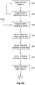
- FIGS. 8A to 8C are a flowchart of a specific example of a method for situational awareness monitoring within an environment
- FIG. 9 is a flowchart of an example of a method of identifying objects as part of a situational awareness monitoring method.
- FIG. 10 is a schematic diagram of an example of a graphical representation of a situational awareness model
- FIG. 11 is a flow chart of an example of a process for image region classification
- FIG. 13 is a flow chart of an example of a process for weighted object detection.
- FIG. 1 An example of a system for performing situational awareness monitoring within an environment will now be described with reference to FIG. 1 .
- the nature of the environment E can vary depending upon the preferred implementation and could include any space where situational awareness monitoring needs to be performed.
- Particular examples include factories, warehouses, storage environments, or similar, although it will be appreciated that the techniques could be applied more broadly, and could be used in indoor and/or outdoor environments.
- the objects could be a wide variety of objects, and in particular moving objects, such as people, animals, vehicles, autonomous or semiautonomous vehicles, such as automated guided vehicles (AGVs), or the like.
- situational awareness monitoring is particularly beneficial in situations where AGVs, or other robotic systems or vehicles, are working alongside people, such as in semi-automated factories. Again however this is not intended to be limiting.
- the system for performing situational awareness monitoring typically includes one or more electronic processing devices 110 , configured to receive image streams from imaging devices 120 , which are provided in the environment E in order to allow images to be captured of the objects 101 , 102 , 103 within the environment E.
- the imaging devices 120 will vary depending upon the preferred implementation, but in one example the imaging devices are low cost imaging devices, such as non-computer vision monoscopic cameras. In one particular example, security cameras can be used, although as will become apparent from the following description, other low cost cameras, such as webcams, or the like, could additionally and/or alternatively be used. It is also possible for a wide range of different imaging devices 120 to be used, and there is no need for the imaging devices 120 to be of a similar type or model.
- the imaging devices 120 are typically positioned so as to provide coverage over a full extent of the environment E, with at least some of the cameras including at least partially overlapping fields of view, so that any objects within the environment E are preferably imaged by two or more of the imaging devices at any one time.
- the imaging devices are typically statically positioned within the environment and may be provided in a range of different positions in order to provide complete coverage.
- the imaging devices could be provided at different heights, and could include a combination of floor, wall and/or ceiling mounted cameras, configured to capture views of the environment from different angles.
- the processing device 110 receives image streams from each of the imaging devices 120 , with the image streams including a plurality of captured images, and including images of the objects 101 , 102 , 103 , within the environment E.
- the above described arrangement provides a system for monitoring environments such as factories, warehouses, mines or the like, allowing movement of objects such as AGVs, people, or other objects, to be tracked. This is used together with situational awareness rules to establish when undesirable conditions arise, such as when an AGV or other vehicle is likely to come into contact or approach a person, or vice versa.
- the system allows corrective actions to be performed automatically, for example to modify operation of the vehicle, or alert a person to the fact that a vehicle is approaching.
- the system utilises a plurality of imaging devices provided within the environment E and operates to utilise images with overlapping fields of view in order to identify object locations.
- This avoids the need for objects to be provided with a detectable feature, such as RFID tags, or similar, although the use of such tags is not excluded as will be described in more detail below.
- this process can be performed using low cost imaging devices, such as security cameras, or the like to be used, which offers a significant commercial value over other systems.
- the benefit is that the cameras are more readily available, known well and have a lower cost as well as can be connected to a single Ethernet cable that communicates and supplies power. This can then connect to a standard off the shelf POE Ethernet Switch as well as standard Power supply regulation.
- this can vastly reduce the cost of installing and configuring such a system, avoiding the need to utilise expensive stereoscopic or computer vision cameras and in many cases allows existing security camera infrastructure to be utilised for situational awareness monitoring.
- the overlapping images are synchronous overlapping images in that they are captured at approximately the same time.
- the requirement for images to be captured at approximately the same time means that the images are captured within a time interval less than that which would result in substantial movement of the object. Whilst this will therefore be dependent on the speed of movement of the objects, the time interval is typically less than about 1 second, less than about 500 ms, less than about 200 ms, or less than about 100 ms.
- the two techniques are used in conjunction, so that the time of receipt of the images is used to validate a time stamp associated with the images, thereby providing an additional level of verification to the determined capture time, and allowing corrective measures to be taken in the event a capture time is not verified.
- synchronous images is not essential, and asynchronous images or other data could be used, depending on the preferred implementation.
- images of an object that are captured asynchronously can result in the object location changing between images.
- suitable techniques such as weighting images, so images captured asynchronously are given a temporal weighting in identifying the object location, as will be described in more detail below.
- Other techniques could also be employed such as assigning an object a fuzzy boundary and/or location, or the like.
- the one or more processing devices are configured to analyse a number of images from an image stream to identify static image regions and then identify object images as images including non-static image regions.
- this involves comparing successive or subsequent images to identify movement that occurs between the images, with it being assessed that the movement component in the image is as a result of an object moving.
- This relies on the fact that the large majority of the environment will remain static, and that in general it is only the objects that will undergo movement between the images. Accordingly, this provides an easy mechanism to identify objects, and reduces the amount of time required to analyse images to detect objects therein.
- the one or more processing devices can be configured to determine a degree of change in appearance for an image region between images in an image stream and then identify objects based on the degree of change.
- the images can be successive images and/or temporally spaced images, with the degree of change being a magnitude and/or rate of change.
- the size and shape of the image region can vary, and may include subsets of pixels, or similar, depending on the preferred implementation. In any event, it will be appreciated that if the image region is largely static, then it is less likely that an object is within the image region, than if the image region is undergoing significant change in appearance, which is indicative of a moving object.
- objects can be identified based on classification of the image region, for example by analysing non-static image regions to identify objects.
- this is achieved by using the image regions to establish masks, which are then used in performing subsequent analysis, for example, with foreground masks being used to identify and track objects, whilst background masks are excluded to reduce processing requirements.
- the processing devices can be configured to identify images including visual effects and then process the images in accordance with the visual effects to thereby identify objects.
- visual effects can result in a change of appearance between images of the same scene, which could therefore be identified as a potential object.
- an AGV may include illumination ahead of the vehicle, which could be erroneously detected as an object separate from the AGV as it results in a change in appearance that moves over time. Similar issues arise with other changes in ambient illumination, such as changes in sunlight within a room, the presence of visual presentation devices, such as displays or monitors, or the like.
- the processing device can be configured to identify image regions including visual effects and then exclude image regions including visual effects and/or classify image regions accounting for the visual effects.
- this could be used to adjust a classification threshold based on identified visual effects, for example by raising the classification threshold so that an image region is less likely to be classified as a non-static image region when changes in visual appearance are detected.
- visual effects could be identified by analyzing images in accordance with defined properties thereby allowing regions meeting those properties to be excluded. For example, this could include identifying illumination having known wavelengths and/or spectral properties, such as corresponding to vehicle warning lights, and then excluding such regions from analysis.
- the processing device is configured to analyse the synchronous overlapping images in order to determine object locations.
- this is performed using a visual hull technique, which is a shape-from-silhouette 3D reconstruction technique.
- visual hull techniques involve identifying silhouettes of objects within the images, and using these to create a back-projected generalized cone (known as a “silhouette cone”) that contains the actual object.
- Silhouette cones from images taken from different viewpoints are used to determine an intersection of the two or more cones, which forms the visual hull, which is a bounding geometry of the actual 3D object. This can then be used to ascertain the location based on known viewpoints of the imaging devices.
- comparing images captured from different viewpoints allows the position of the object within the environment E to be determined.
- such a visual hull approach is not required.
- the object includes machine readable visual coded data, such as a fiducial marker, or an April Tag, described in “AprilTag: A robust and flexible visual fiducial system” by Edwin Olson in Proceedings of the IEEE International Conference on Robotics and Automation (ICRA), 2011, then the location can be derived through a visual analysis of the fiducial markers in the captured images.
- machine readable visual coded data such as a fiducial marker, or an April Tag, described in “AprilTag: A robust and flexible visual fiducial system” by Edwin Olson in Proceedings of the IEEE International Conference on Robotics and Automation (ICRA), 2011, then the location can be derived through a visual analysis of the fiducial markers in the captured images.
- the approach uses a combination of fiducial markings and multiple images, allowing triangulation of different images containing the fiducial markings, to allowing the location of the fiducial markings and hence the object, to be calculated with a higher degree of accuracy.
- candidate objects can be incorporated into a three dimensional model of the environment, and examples of such a model are described in more detail below.
- the model can then be analysed to identify potential occlusions, for example when another object is positioned between the object and an imaging device, by back-projecting objects from the three dimensional model into the 2D imaging plane of the imaging device.
- the potential occlusions can then be used to validate candidate objects, for example allowing the visual hull process to be performed taking the occlusion into account. Examples of these issues are described in “Visual Hull Construction in the Presence of Partial Occlusion” by Li Guan, Sudipta Sinha, Jean-Sebastien Franco, Marc Pollefeys.
- the potential occlusions are accounted for by having the processing device classify image regions as occluded image regions if they contain potential occlusions, taking this into account when identifying the object. Whilst this could involve simply excluding occluded image regions from the analysis, typically meaningful information would be lost with this approach, and as a result objects may be inaccurately identified and/or located. Accordingly, in another example, this can be achieved by weighting different ones of the corresponding images, with the weighting being used to assess the likely impact of the occlusion and hence the accuracy of any resulting object detection.
- an object score is calculated associated with corresponding image regions, with the object score being indicative of certainty associated with detection of an object in the corresponding image regions. Once calculated the object score can be used to identify objects, for example assessing an object to be accurately identified if the score exceeds a score threshold.
- the factors could also take into account a time of image capture, which can assist in allowing asynchronous data capture to be used. In this instance, if one of the overlapping images is captured at a significantly different time to the other images, this may be given a lower weighting in terms of identifying the object given the object may have moved in the intervening time.
- calculating a score for the image captured by each imaging device could be used to weight each of the images, so that the degree to which the image is relied upon in the overall object detection process can take into account factors such as the quality of the image, occlusions, visual effects, how well the object is imaged, or the like, which can in turn allow object detection to be performed more accurately.
- determining the location of the objects typically requires knowledge of the positioning of the imaging devices within the environment, and so the processing device is configured to interpret the images in accordance with a known position of the image devices.
- position information is embodied in calibration data which is used in order to interpret the images.
- the calibration data includes intrinsic calibration data indicative of imaging properties of each imaging device and extrinsic calibration data indicative of the relative positioning of the imaging devices within the environment E. This allows the processing device to correct images to account for any imaging distortion in the captured images, and also to account for the position of the imaging devices relative to the environment E.
- the calibration data is typically generated during a calibration process.
- intrinsic calibration data can be generated based on images of defined patterns captured from different positions using an imaging device.
- the defined patterns could be of any appropriate form and may include patterns of dots or similar, fiducial markers, or the like.
- the images are analysed to identify distortions of the defined patterns in the image, which can in turn be used to generate calibration data indicative of image capture properties of the imaging device.
- image capture properties can include things such as a depth of field, a lens aperture, lens distortion, or the like.
- the situational awareness rules will vary depending on the preferred implementation, as well as the nature of the environment, and the objects within the environment.
- the situational awareness rules are indicative of one or more of permitted object travel paths, permitted object movements, permitted proximity limits for different objects, permitted zones for objects, or denied zones of objects.
- Such rules can be generated using a variety of techniques, but are typically generated manually through an understanding of the operation and interaction of objects in the environment.
- a rules engine can be used to at least partially automate the task.
- the rules engine typically operates by receiving a rules document, and parsing using natural language processing, to identify logic expressions and object types. An object identifier is then determined for each object type, either by retrieving these based on an object type of the object or by generating these as needed.
- the logic expressions are then used to generate the object rules by converting the logic expressions into a trigger event and an action, before uploading these to the tag. For example, the logic expressions are often specified within a rules text in terms of “If . . . then . . .
- rules are generated, actions to be taken in response to a breach of the rules can also be defined, with this information being stored as rules data in a rules database.
- the rules when the rules are created, the rules are associated with one or more object identities, which can be indicative of an object type and/or can be uniquely indicative of the particular object, allowing object situational awareness rules to be defined for different types of objects, or different individual objects.
- This allows the processing device to subsequently retrieve relevant rules based on the object identities of objects within the environment.
- the one or more processing devices are configured to determine an object identity for at least one object and then compare the object movement to situational awareness rules at least in part using the object identity.
- the processing device can select one or more situational awareness rules in accordance with the object identity, and then compare the object movement to the selected situational awareness rule.
- the object identity can be determined utilising a number of different techniques, depending for example on the preferred implementation, and/or, the nature of the object. For example, if the object does not include any form of encoded identifier, this could be performed using image recognition techniques. In the case of identifying people for example, the people will have a broadly similar appearance will generally be quite different to that of an AGV and accordingly, people could be identified using image recognition techniques performed on or more of the images. It will be noted that this does not necessarily require discrimination of different individuals, although this may be performed in some cases.
- identities, and in particular object types could be identified through an analysis of movement.
- movement of AGVs will typically tend to follow predetermined patterns and/or have typically characteristics such as constant speed and/or direction changes.
- characteristics such as constant speed and/or direction changes.
- AGVs and humans to be distinguished based on an analysis of movement patterns.
- an object can be associated with machine readable code data indicative of an object identity.
- the processing devices can be configured to determine the object identity using the machine readable coded data.
- the machine readable coded data could be encoded in any one of a number of ways depending on the preferred implementation. In one example, this can be achieved using visual coded data such as a bar code, QR code or more typically an April Tag, which can then be detected by analysing images to identify the visible machine readable coded data in the image allowing this to be decoded by the processing device.
- objects may be associated with tags, such as short range wireless communication protocol tags, RFID (Radio Frequency Identification) tags, Bluetooth tags, or similar, in which case the machine readable coded data could be retrieved from a suitable tag reader.
- an object could be uniquely identified through detection of machine readable coded data when passing by a suitable reader.
- this identity can be maintained by keeping track of the object as it moves within the environment. This means that the object does not need to pass by a reader again in order to be identified, which is particularly useful in circumstances where objects are only identified on limited occasions, such as upon entry into an area, as may occur for example when an individual uses an access card to enter a room.
- the one or more processing devices are configured to generate an environment model indicative of the environment, a location of imaging devices in the environment, locations of client devices, such as alerting beacons, current object locations, object movements, predicted object locations, predicted object movements, or the like.
- the environment model can be used to maintain a record of recent historical movements, which in turn can be used to assist in tracking objects that are temporarily stationary, and also to more accurately identify situational awareness events.
- actions can be taken. This can include, but is not limited to, recording an indication of the situational awareness event, generating a notification indicative of the situational awareness event, causing an output device to generate an output indicative of the situational awareness event, including generating an audible and/or visual output, activating an alarm, or causing operation of an object to be controlled.
- notifications could be provided to overseeing supervisors or operators, alerts could be generated within the environment, for example to notify humans of a potential situational awareness event, such as a likelihood of imminent collision, or could be used to control autonomous or semi-autonomous vehicles, such as AGVs, allowing the vehicle control system to stop the vehicle and/or change operation of the vehicle in some other manner, thereby allowing an accident or other event to be avoided.
- a potential situational awareness event such as a likelihood of imminent collision
- AGVs autonomous or semi-autonomous vehicles
- a number of processing systems 310 are coupled via communications networks 340 , such as the Internet, and/or one or more local area networks (LANs), to a number of client devices 330 and imaging devices 320 .
- communications networks 340 such as the Internet, and/or one or more local area networks (LANs)
- client devices 330 and imaging devices 320 are for the purpose of example only, and in practice the processing systems 310 , imaging devices 320 and client devices 330 can communicate via any appropriate mechanism, such as via wired or wireless connections, including, but not limited to mobile networks, private networks, such as an 802.11 networks, the Internet, LANs, WANs, or the like, as well as via direct or point-to-point connections, such as Bluetooth, or the like.
- the processing systems 310 are configured to receiving image streams from the imaging devices, analyse the image streams and identify situational awareness events.
- the processing systems 310 can also be configured to implement actions, such as generating notifications and/or alerts, optionally displayed via client devices or other hardware, control operations of AGVs, or similar, or create and provide access to an environment model.
- the processing system 310 is a shown as a single entity, it will be appreciated that the processing system 310 can be distributed over a number of geographically separate locations, for example by using processing systems 310 and/or databases that are provided as part of a cloud based environment.
- the above described arrangement is not essential and other suitable configurations could be used.
- the processing system 310 includes at least one microprocessor 411 , a memory 412 , an optional input/output device 413 , such as a keyboard and/or display, and an external interface 414 , interconnected via a bus 415 , as shown.
- the external interface 414 can be utilised for connecting the processing system 310 to peripheral devices, such as the communications network 340 , databases, other storage devices, or the like.
- peripheral devices such as the communications network 340 , databases, other storage devices, or the like.
- a single external interface 414 is shown, this is for the purpose of example only, and in practice multiple interfaces using various methods (eg. Ethernet, serial, USB, wireless or the like) may be provided.
- the client devices 330 may be formed from any suitable processing system, such as a suitably programmed PC, Internet terminal, lap-top, or hand-held PC, and in one preferred example is either a tablet, or smart phone, or the like.
- the client device 330 is a standard processing system such as an Intel Architecture based processing system, which executes software applications stored on non-volatile (e.g., hard disk) storage, although this is not essential.
- the client devices 330 can be any electronic processing device such as a microprocessor, microchip processor, logic gate configuration, firmware optionally associated with implementing logic such as an FPGA (Field Programmable Gate Array), or any other electronic device, system or arrangement.
- one or more processing systems 310 act to monitor image streams from the image devices 320 , analyse the image streams to identify situational awareness events, and then perform required actions as needed. User interaction can be performed based on user inputs provided via the client devices 330 , with resulting notification of model visualisations being displayed by the client devices 330 .
- the server 310 employs a visual hull analysis to locate objects in the environment, using this information to update an environment model at step 640 .
- the environment model is a model of the environment including information regarding the current and optionally historical location of objects within the environment. This can then be used to track object movements and/or locations at step 650 .
- steps 700 to 720 are repeated for each individual imaging device to be used, and can be performed in situ, or prior to placement of the imaging devices.
- FIGS. 8A to 8C An example of a process for performing situational monitoring will now be described in more detail with reference to FIGS. 8A to 8C .
- step 800 image streams are captured by the imaging devices 310 with these being uploaded to the server 310 at step 802 .
- Steps 800 and 802 are repeated substantially continuously so that image streams are presented to the server 310 substantially in real time.
- the server 310 analyses successive images and operates to subtract static regions from the images at step 812 . This is used to identify moving components within each image, which are deemed to correspond to objects moving within the environment.
- synchronous overlapping images are identified by identifying images from different image streams that were captured substantially simultaneously, and which include objects captured from different viewpoints. Identification of overlapping images can be performed using the extrinsic calibration data, allowing cameras with overlapping field of view to be identified, and can also involve analysis of images including objects to identify the same object in the different images. This can examine the presence of machine readable coded data, such as April Tags within the image, or can use recognition techniques to identify characteristics of the objects, such as object colours, size, shape, or the like.
- the images are analysed to identify object locations at step 818 .
- This can be performed using coded fiducial markings, or by performing a visual hull analysis, in the event that such markings are not available. It will be appreciated that in order to perform the analysis this must take into account the extrinsic and intrinsic calibration data to correct the images for properties of the imaging device, such as any image distortion, then further utilising knowledge of the relative position of the respective imaging devices in order to interpret the object location and/or a rough shape in the case of performing a visual hull analysis.
- the server 310 Having determined an object location, at step 820 the server 310 operates to determine an object identity.
- the manner in which an object is identified will vary depending on the nature of the object, and any identifying data, and an example identification process will now be described in more detail with reference to FIG. 9 .
- a visual analysis can be performed using image recognition techniques at step 935 in order to attempt to identify the object at step 940 . It will be appreciated that this may only be sufficient to identify a type of object, such as a person, and might not allow discrimination between objects of the same type. Additionally, in some situations, this might not allow for identification of objects, in which case the objects can be assigned an unknown identity.
- a static object will remain present in the environment model based on its last known location, so that when the object recommences movement, and is located within the images, this can be matched to the static object within the environment model, based on the coincident location of the objects, although it will be appreciated that this may not be required depending on how objects are detected.
- the object is added to the environment model at step 826 .
- the object location and/or movement can be updated at step 828 .
- any object movement can be extrapolated in order to predict future object movement.
- this will examine a trend in historical movement patterns and use this to predict a likely future movement over a short period of time, allowing the server 310 to predict where objects will be a short time in advance.
- this can be performed using machine learning techniques or similar, taking into account previous movements for the object, or objects of a similar type, as well as other information, such as defined intended travel paths.
- the rules are typically defined based on an understanding of requirements of the particular environment and the objects within the environment.
- the rules are typically defined for specific objects, object types or for multiple objects, so that different rules can be used to assess situational awareness for different objects.
- the situational awareness rules are typically stored together with associated object identities, either in the form of specific object identifiers, or specified object types, as rule data, allowing the respective rules to be retrieved for each detected object within the environment.
- client devices 330 such as mobile phones, can be used for displaying alerts, so that alerts could be broadcast to relevant individuals in the environment. This could include broadcast notifications pushed to any available client device 330 , or could include directing notifications to specific client devices 330 associated with particular users. For example, if an event occurs involving a vehicle, a notification could be provided to the vehicle operator and/or a supervisor.
- client devices 330 can include displays or other output devices, such as beacons configured to generate audible and/or visual alerts, which can be provided at specific defined locations in the environment, or associated with objects, such as AGVs. In this instance, if a collision with an AGV or other object is imminent, a beacon on the object can be activated alerting individuals to the potential collision, and thereby allowing the collision to be avoided.
- the client device 330 can form part of, or be coupled to, a control system of an object such as an autonomous or semi-autonomous vehicle, allowing the server 310 to instruct the client device 330 to control the object, for example causing movement of the object to cease until the situational awareness event is mitigated.
- a control system of an object such as an autonomous or semi-autonomous vehicle
- client devices 330 can be associated with respective objects, or could be positioned within the environment, and that this will be defined as part of a set-up process.
- client devices 330 associated with objects could be identified in the object data, so that when an action is be performed associated with a respective object, the object data can be used to retrieve details of the associated client device and thereby push notifications to the respective client device.
- details of static client devices could be stored as part of the environment model, with details being retrieved in a similar manner as needed.
- the server 310 In addition to performing situational awareness monitoring, and performing actions as described above, the server 310 also maintains the environment model and allows this to be viewed by way of a graphical representation. This can be achieved via a client device 330 , for example, allowing a supervisor or other individual to maintain an overview of activities within the environment, and also potentially view situational awareness events as they arise.
- a graphical representation of an environment model will now be described in more detail with reference to FIG. 10 .
- the positioning of imaging devices 320 can be performed as part of the calibration process described above, and may involve having a user manually position icons at approximate locations, with the positioning being refined as calibration is performed.
- positioning of the client devices could also be performed manually, in the case of static client devices 320 , and/or by associating a client device 320 with an object, so that the client device location is added to the model when the object is detected within the environment.
- the representation also displays additional details associated with objects.
- the object 1001 is rectangular in shape, which could be used to denote an object type, such as an AGV, with the icon having a size similar to the footprint of the actual physical AGV.
- the object 1001 has an associated identifier ID 1001 shown, which corresponds to the detected identity of the object.
- the object has an associated pre-programmed travel path 1001 . 1 , which is the path the AGV is expected to follow, whilst a client device icon 1030 . 1 is shown associated with the object 1001 , indicating that a client device is provided on the AGV.
- Object 1004 is a second AGV, in this instance having an unknown identifier represented by ID???.
- the AGV 1004 has a historical travel path 1004 . 2 and a predicted travel path 1004 . 3 .
- the predicted travel path intersects with the predetermined path 1001 . 1 of the AGV 1001 and it is anticipated that an intersection may occur in the region 1004 . 4 , which is highlighted as being a potential issue.
- an image region is identified.
- the image region can be arbitrarily defined, for example by segmenting each image based on a segmentation grid, or similar, or may be based on the detection of movement in the previous images.
- the server optionally assesses a history of the image region at step 1110 , which can be performed in order to identify if the image region has recently been assessed as non-static, which is in turn useful in identifying objects that have recently stopped moving.
- visual effects can be identified.
- Visual effects can be identified in any appropriate manner depending on the nature of the visual effect and the preferred implementation. For example, this may involve analysing signals from illumination sensors to identify changes in background or ambient illumination. Alternatively this could involve retrieving information regarding visual effect locations within the environment, which could be defined during a calibration process, for example by specifying the location of screens or displays in the environment. This can also involve analysing the images in order to identify visual effects, for example to identify parts of the image including a spectral response known to correspond to a visual effect, such as a particular illumination source. This process is performed to account for visual effects and ensure these are not incorrectly identified as moving objects.
- a classification threshold is set, which is used to assess whether an image region is static or non-static.
- the classification threshold can be a default value, which is then modified as required based on the image region history and/or identified visual effects. For example, if the individual region history indicates that the image region was previously or recently classified as non-static, the classification threshold can be raised from a default level to reduce the likelihood of the image region are being classified as static in the event that an object has recently stopped moving. This in effect increases the learning duration for assessing changes in the respective image region, which is useful in tracking temporarily stationary objects. Similarly, if visual effects are present within the region, the threat classification threshold can be modified to reduce the likelihood of the image region are being misclassified.
- occlusions may arise in which objects are at least partially obstructed from an imaging device, and an example of a process for occlusion detection and mitigation will now be described with reference to FIG. 12 .
- corresponding image regions are identified in multiple overlapping images at step 1200 .
- the corresponding image regions are image regions from multiple overlapping images that are a view of a common volume in the environment, such as one or more voxels.
- one or more candidate objects are identified, for example using a visual hull technique.
- any candidate objects are added to a three-dimensional model, such as a model similar to that described above with respect to FIG. 10 .
- the candidate objects are back projected onto the imaging plane of an imaging device that captured an image of the candidate objects. This is performed in order to ascertain whether the candidate objects are overlapping and hence an occlusion may have occurred.
- step 1300 corresponding image regions are identified in a manner similar to that described with respect to step 1200 .
- each image region is assessed, with the assessment being used to ascertain the likelihood that the detection of an object is accurate.
- successful detection of an object will be influenced by a range of factors, including image quality such as image resolution or distortion, camera geometry such as a camera distance and angle, image region history such as whether the image region was previous static or non-static, the presence or absence of occlusions or visual effects, a degree of asynchronicity between collected data, such as difference in capture time of the overlapping images, or the like.
- this process attempts to take these factors into account by assigning a value based on each factor, and using this to determine an image region score at step 1320 .
- the value for each factor will typically represent whether the factor will positively or negatively influence successful detection of an object so if an occlusion is at present a value of ⁇ 1 could be used, whereas if an occlusion is not present a value of +1 could be used, indicating that it is more likely an object detection would be correct than if an occlusion is present.
- the image region scores can then be used in the identification of objects.
- the visual hull process is performed, using the image region score as a weighting.
- an image region with a low image region score which is less likely to have accurately imaged the object, will be given a low weighting in the visual hull process. Consequently, this will have less influence on the object detection process, so the process is more heavily biased to image regions having a higher image region source.
- a composite object score can be calculated by combining the image region score of each of the corresponding image regions at step 1340 , with the resulting value being compared to a threshold at step 1350 , with this being used to assess whether an object has been successfully identified at step 1360 .
Landscapes
- Engineering & Computer Science (AREA)
- General Physics & Mathematics (AREA)
- Physics & Mathematics (AREA)
- Multimedia (AREA)
- Computer Vision & Pattern Recognition (AREA)
- Theoretical Computer Science (AREA)
- Library & Information Science (AREA)
- Business, Economics & Management (AREA)
- Human Computer Interaction (AREA)
- General Health & Medical Sciences (AREA)
- Health & Medical Sciences (AREA)
- Social Psychology (AREA)
- Psychiatry (AREA)
- Emergency Management (AREA)
- Tourism & Hospitality (AREA)
- Data Mining & Analysis (AREA)
- Evolutionary Computation (AREA)
- Educational Administration (AREA)
- General Engineering & Computer Science (AREA)
- Evolutionary Biology (AREA)
- Bioinformatics & Computational Biology (AREA)
- Bioinformatics & Cheminformatics (AREA)
- Artificial Intelligence (AREA)
- Computer Security & Cryptography (AREA)
- Development Economics (AREA)
- Signal Processing (AREA)
- Life Sciences & Earth Sciences (AREA)
- Economics (AREA)
- Human Resources & Organizations (AREA)
- Marketing (AREA)
- Primary Health Care (AREA)
- Strategic Management (AREA)
- General Business, Economics & Management (AREA)
- Image Analysis (AREA)
- Alarm Systems (AREA)
Abstract
Description
Claims (21)
Applications Claiming Priority (3)
| Application Number | Priority Date | Filing Date | Title |
|---|---|---|---|
| AU2019900442A AU2019900442A0 (en) | 2019-02-12 | Situational awareness monitoring | |
| AU2019900442 | 2019-02-12 | ||
| PCT/AU2020/050113 WO2020163908A1 (en) | 2019-02-12 | 2020-02-11 | Situational awareness monitoring |
Publications (2)
| Publication Number | Publication Date |
|---|---|
| US20220004775A1 US20220004775A1 (en) | 2022-01-06 |
| US11468684B2 true US11468684B2 (en) | 2022-10-11 |
Family
ID=72043762
Family Applications (1)
| Application Number | Title | Priority Date | Filing Date |
|---|---|---|---|
| US17/417,315 Active 2040-02-11 US11468684B2 (en) | 2019-02-12 | 2020-02-11 | Situational awareness monitoring |
Country Status (7)
| Country | Link |
|---|---|
| US (1) | US11468684B2 (en) |
| EP (1) | EP3925207A4 (en) |
| JP (1) | JP7282186B2 (en) |
| KR (1) | KR102724007B1 (en) |
| CN (1) | CN113557713B (en) |
| AU (2) | AU2020222504B2 (en) |
| WO (1) | WO2020163908A1 (en) |
Cited By (2)
| Publication number | Priority date | Publication date | Assignee | Title |
|---|---|---|---|---|
| US20220332503A1 (en) * | 2019-09-12 | 2022-10-20 | Commonwealth Scientific And Industrial Research Organisation | Object moving system |
| US12243105B2 (en) * | 2014-04-25 | 2025-03-04 | State Farm Mutual Automobile Insurance Company | System and method for virtual inspection of a structure |
Families Citing this family (15)
| Publication number | Priority date | Publication date | Assignee | Title |
|---|---|---|---|---|
| US10861184B1 (en) * | 2017-01-19 | 2020-12-08 | X Development Llc | Object pose neural network system |
| WO2020170963A1 (en) * | 2019-02-20 | 2020-08-27 | 日本電気株式会社 | Processing device, processing method, and program |
| US12128887B1 (en) * | 2019-04-19 | 2024-10-29 | Zoox, Inc. | Dynamic object relevance determination |
| WO2022216708A1 (en) * | 2021-04-09 | 2022-10-13 | Iris Technology Inc. | Tracking objects across images |
| KR102887298B1 (en) * | 2021-11-09 | 2025-11-19 | 한국전자통신연구원 | System and method for the split array of multiple images based data construction and training |
| US12482268B2 (en) | 2021-11-09 | 2025-11-25 | Electronics And Telecommunications Research Institute | Data construction and learning system and method based on method of splitting and arranging multiple images |
| KR102649342B1 (en) * | 2022-04-29 | 2024-03-19 | 사회적협동조합 어우리 | Precise detection system for events of CCTV split images |
| JP7753169B2 (en) * | 2022-08-29 | 2025-10-14 | カシオ計算機株式会社 | Detection method, detection device, and program |
| US20240078799A1 (en) * | 2022-09-02 | 2024-03-07 | Electronics And Telecommunications Research Institute | Intruder detection method based on multiple camera images and video surveillance system suitable for the same |
| EP4343709B1 (en) * | 2022-09-23 | 2024-10-30 | Axis AB | Method and image-processing device for determining a probability value indicating that an object captured in a stream of image frames belongs to an object type |
| CN115984731A (en) * | 2022-12-01 | 2023-04-18 | 甘肃英特立科技发展有限公司 | A Situation Awareness Intelligent Decision-Making System Based on Machine Vision |
| US12450906B2 (en) * | 2023-01-30 | 2025-10-21 | Verint Americas Inc. | System and method for tagging untagged events |
| EP4439482B1 (en) * | 2023-03-30 | 2025-01-15 | Axis AB | Masking a detected object in a video stream |
| CN117351188A (en) * | 2023-09-07 | 2024-01-05 | 三星(中国)半导体有限公司 | Identification system and identification method |
| CN120354119B (en) * | 2025-06-26 | 2025-08-19 | 中国铁塔股份有限公司四川省分公司 | Target situation awareness method and system based on low-altitude intelligent network |
Citations (45)
| Publication number | Priority date | Publication date | Assignee | Title |
|---|---|---|---|---|
| US4942539A (en) | 1988-12-21 | 1990-07-17 | Gmf Robotics Corporation | Method and system for automatically determining the position and orientation of an object in 3-D space |
| US5323470A (en) | 1992-05-08 | 1994-06-21 | Atsushi Kara | Method and apparatus for automatically tracking an object |
| WO1998019875A1 (en) | 1996-11-05 | 1998-05-14 | Vernon Joel Grant | A modular wheel assembly |
| WO2000032462A1 (en) | 1998-11-30 | 2000-06-08 | Vernon Joel Grant | A modular wheel and/or conventional wheel assembly and control system |
| US20020196330A1 (en) * | 1999-05-12 | 2002-12-26 | Imove Inc. | Security camera system for tracking moving objects in both forward and reverse directions |
| US6647328B2 (en) | 1998-06-18 | 2003-11-11 | Kline And Walker Llc | Electrically controlled automated devices to control equipment and machinery with remote control and accountability worldwide |
| US6711279B1 (en) | 2000-11-17 | 2004-03-23 | Honeywell International Inc. | Object detection |
| US20050078852A1 (en) * | 2003-10-10 | 2005-04-14 | Buehler Christopher J. | Method of counting objects in a monitored environment and apparatus for the same |
| US6922632B2 (en) | 2002-08-09 | 2005-07-26 | Intersense, Inc. | Tracking, auto-calibration, and map-building system |
| US7221775B2 (en) | 2002-11-12 | 2007-05-22 | Intellivid Corporation | Method and apparatus for computerized image background analysis |
| US7257237B1 (en) | 2003-03-07 | 2007-08-14 | Sandia Corporation | Real time markerless motion tracking using linked kinematic chains |
| US20080036593A1 (en) | 2006-08-04 | 2008-02-14 | The Government Of The Us, As Represented By The Secretary Of The Navy | Volume sensor: data fusion-based, multi-sensor system for advanced damage control |
| US7576847B2 (en) | 2006-04-21 | 2009-08-18 | Faro Technologies, Inc. | Camera based six degree-of-freedom target measuring and target tracking device with rotatable mirror |
| US7729511B2 (en) | 2002-09-24 | 2010-06-01 | Pilz Gmbh & Co. Kg | Method and device for safeguarding a hazardous area |
| US20100166260A1 (en) * | 2008-12-25 | 2010-07-01 | Ching-Chun Huang | Method for automatic detection and tracking of multiple targets with multiple cameras and system therefor |
| US7768549B2 (en) | 2001-06-08 | 2010-08-03 | Honeywell International Inc. | Machine safety system with mutual exclusion zone |
| US7929017B2 (en) * | 2004-07-28 | 2011-04-19 | Sri International | Method and apparatus for stereo, multi-camera tracking and RF and video track fusion |
| US20110115909A1 (en) | 2009-11-13 | 2011-05-19 | Sternberg Stanley R | Method for tracking an object through an environment across multiple cameras |
| US8253792B2 (en) | 2009-08-28 | 2012-08-28 | GM Global Technology Operations LLC | Vision system for monitoring humans in dynamic environments |
| US8260736B1 (en) | 2008-09-12 | 2012-09-04 | Lockheed Martin Corporation | Intelligent system manager system and method |
| US8289390B2 (en) | 2004-07-28 | 2012-10-16 | Sri International | Method and apparatus for total situational awareness and monitoring |
| US20130250050A1 (en) * | 2012-03-23 | 2013-09-26 | Objectvideo, Inc. | Video surveillance systems, devices and methods with improved 3d human pose and shape modeling |
| CN203331022U (en) | 2013-06-21 | 2013-12-11 | 朱广俊 | Modular wheel-robot capable being assembled |
| US8757309B2 (en) | 2004-06-15 | 2014-06-24 | Massachusetts Institute Of Technology | Autonomous modular vehicle wheel assembly |
| US20140176726A1 (en) * | 2012-12-20 | 2014-06-26 | Thales Holdings Uk Plc | Image processor for processing images received from a plurality of image sensors |
| CN104049586A (en) | 2013-03-15 | 2014-09-17 | 费希尔-罗斯蒙特系统公司 | Mobile control room with real-time context awareness |
| WO2014149154A1 (en) | 2013-03-15 | 2014-09-25 | Battelle Memorial Institute | Multi-domain situational awareness for infrastructure monitoring |
| US20140303767A1 (en) | 2011-12-09 | 2014-10-09 | Daimler Ag | Method for Operating a Production Plant |
| US8885559B2 (en) | 2009-03-20 | 2014-11-11 | Innovative Wireless Technologies, Inc. | Method and apparatus for reliable communications in underground and hazardous areas |
| US20150153312A1 (en) | 2013-11-30 | 2015-06-04 | Saudi Arabian Oil Company | Modular Mobile Inspection Vehicle |
| US20150172545A1 (en) * | 2013-10-03 | 2015-06-18 | Flir Systems, Inc. | Situational awareness by compressed display of panoramic views |
| US9251598B2 (en) | 2014-04-10 | 2016-02-02 | GM Global Technology Operations LLC | Vision-based multi-camera factory monitoring with dynamic integrity scoring |
| US9256944B2 (en) | 2014-05-19 | 2016-02-09 | Rockwell Automation Technologies, Inc. | Integration of optical area monitoring with industrial machine control |
| US9476730B2 (en) | 2014-03-18 | 2016-10-25 | Sri International | Real-time system for multi-modal 3D geospatial mapping, object recognition, scene annotation and analytics |
| US20170142403A1 (en) | 2015-11-16 | 2017-05-18 | Abb Technology Ag | Automatically scanning and representing an environment having a plurality of features |
| US20170280063A1 (en) * | 2016-03-22 | 2017-09-28 | Research & Business Foundation Sungkyunkwan University | Stereo image generating method using mono cameras in vehicle and providing method for omnidirectional image including distance information in vehicle |
| US20170313332A1 (en) | 2002-06-04 | 2017-11-02 | General Electric Company | Autonomous vehicle system and method |
| CN107505940A (en) | 2017-08-08 | 2017-12-22 | 速感科技(北京)有限公司 | Double laser radar control method, system and localization method on automated guided vehicle |
| US9904852B2 (en) | 2013-05-23 | 2018-02-27 | Sri International | Real-time object detection, tracking and occlusion reasoning |
| US9914218B2 (en) | 2015-01-30 | 2018-03-13 | Toyota Motor Engineering & Manufacturing North America, Inc. | Methods and apparatuses for responding to a detected event by a robot |
| WO2018119450A1 (en) | 2016-12-23 | 2018-06-28 | Gecko Robotics, Inc. | Inspection robot |
| WO2019005727A1 (en) | 2017-06-30 | 2019-01-03 | Paha Designs, Llc | Low gravity all-surface vehicle |
| CN109353407A (en) | 2018-09-19 | 2019-02-19 | 西安交通大学 | An omnidirectional driving vehicle modular drive steering system and vehicle |
| US20190160938A1 (en) | 2016-08-16 | 2019-05-30 | Transcom R&D Pty. Ltd. | A modular electric wheel assembly for an electric vehicle |
| US10394234B2 (en) | 2017-12-18 | 2019-08-27 | The Boeing Company | Multi-sensor safe path system for autonomous vehicles |
Family Cites Families (2)
| Publication number | Priority date | Publication date | Assignee | Title |
|---|---|---|---|---|
| US9471912B2 (en) * | 2014-02-06 | 2016-10-18 | Verto Analytics Oy | Behavioral event measurement system and related method |
| US9524426B2 (en) * | 2014-03-19 | 2016-12-20 | GM Global Technology Operations LLC | Multi-view human detection using semi-exhaustive search |
-
2020
- 2020-02-11 AU AU2020222504A patent/AU2020222504B2/en not_active Withdrawn - After Issue
- 2020-02-11 CN CN202080014133.8A patent/CN113557713B/en active Active
- 2020-02-11 WO PCT/AU2020/050113 patent/WO2020163908A1/en not_active Ceased
- 2020-02-11 EP EP20755544.2A patent/EP3925207A4/en active Pending
- 2020-02-11 JP JP2021546697A patent/JP7282186B2/en active Active
- 2020-02-11 KR KR1020217028583A patent/KR102724007B1/en active Active
- 2020-02-11 US US17/417,315 patent/US11468684B2/en active Active
- 2020-11-16 AU AU2020270461A patent/AU2020270461B2/en active Active
Patent Citations (45)
| Publication number | Priority date | Publication date | Assignee | Title |
|---|---|---|---|---|
| US4942539A (en) | 1988-12-21 | 1990-07-17 | Gmf Robotics Corporation | Method and system for automatically determining the position and orientation of an object in 3-D space |
| US5323470A (en) | 1992-05-08 | 1994-06-21 | Atsushi Kara | Method and apparatus for automatically tracking an object |
| WO1998019875A1 (en) | 1996-11-05 | 1998-05-14 | Vernon Joel Grant | A modular wheel assembly |
| US6647328B2 (en) | 1998-06-18 | 2003-11-11 | Kline And Walker Llc | Electrically controlled automated devices to control equipment and machinery with remote control and accountability worldwide |
| WO2000032462A1 (en) | 1998-11-30 | 2000-06-08 | Vernon Joel Grant | A modular wheel and/or conventional wheel assembly and control system |
| US20020196330A1 (en) * | 1999-05-12 | 2002-12-26 | Imove Inc. | Security camera system for tracking moving objects in both forward and reverse directions |
| US6711279B1 (en) | 2000-11-17 | 2004-03-23 | Honeywell International Inc. | Object detection |
| US7768549B2 (en) | 2001-06-08 | 2010-08-03 | Honeywell International Inc. | Machine safety system with mutual exclusion zone |
| US20170313332A1 (en) | 2002-06-04 | 2017-11-02 | General Electric Company | Autonomous vehicle system and method |
| US6922632B2 (en) | 2002-08-09 | 2005-07-26 | Intersense, Inc. | Tracking, auto-calibration, and map-building system |
| US7729511B2 (en) | 2002-09-24 | 2010-06-01 | Pilz Gmbh & Co. Kg | Method and device for safeguarding a hazardous area |
| US7221775B2 (en) | 2002-11-12 | 2007-05-22 | Intellivid Corporation | Method and apparatus for computerized image background analysis |
| US7257237B1 (en) | 2003-03-07 | 2007-08-14 | Sandia Corporation | Real time markerless motion tracking using linked kinematic chains |
| US20050078852A1 (en) * | 2003-10-10 | 2005-04-14 | Buehler Christopher J. | Method of counting objects in a monitored environment and apparatus for the same |
| US8757309B2 (en) | 2004-06-15 | 2014-06-24 | Massachusetts Institute Of Technology | Autonomous modular vehicle wheel assembly |
| US8289390B2 (en) | 2004-07-28 | 2012-10-16 | Sri International | Method and apparatus for total situational awareness and monitoring |
| US7929017B2 (en) * | 2004-07-28 | 2011-04-19 | Sri International | Method and apparatus for stereo, multi-camera tracking and RF and video track fusion |
| US7576847B2 (en) | 2006-04-21 | 2009-08-18 | Faro Technologies, Inc. | Camera based six degree-of-freedom target measuring and target tracking device with rotatable mirror |
| US20080036593A1 (en) | 2006-08-04 | 2008-02-14 | The Government Of The Us, As Represented By The Secretary Of The Navy | Volume sensor: data fusion-based, multi-sensor system for advanced damage control |
| US8260736B1 (en) | 2008-09-12 | 2012-09-04 | Lockheed Martin Corporation | Intelligent system manager system and method |
| US20100166260A1 (en) * | 2008-12-25 | 2010-07-01 | Ching-Chun Huang | Method for automatic detection and tracking of multiple targets with multiple cameras and system therefor |
| US8885559B2 (en) | 2009-03-20 | 2014-11-11 | Innovative Wireless Technologies, Inc. | Method and apparatus for reliable communications in underground and hazardous areas |
| US8253792B2 (en) | 2009-08-28 | 2012-08-28 | GM Global Technology Operations LLC | Vision system for monitoring humans in dynamic environments |
| US20110115909A1 (en) | 2009-11-13 | 2011-05-19 | Sternberg Stanley R | Method for tracking an object through an environment across multiple cameras |
| US20140303767A1 (en) | 2011-12-09 | 2014-10-09 | Daimler Ag | Method for Operating a Production Plant |
| US20130250050A1 (en) * | 2012-03-23 | 2013-09-26 | Objectvideo, Inc. | Video surveillance systems, devices and methods with improved 3d human pose and shape modeling |
| US20140176726A1 (en) * | 2012-12-20 | 2014-06-26 | Thales Holdings Uk Plc | Image processor for processing images received from a plurality of image sensors |
| CN104049586A (en) | 2013-03-15 | 2014-09-17 | 费希尔-罗斯蒙特系统公司 | Mobile control room with real-time context awareness |
| WO2014149154A1 (en) | 2013-03-15 | 2014-09-25 | Battelle Memorial Institute | Multi-domain situational awareness for infrastructure monitoring |
| US9904852B2 (en) | 2013-05-23 | 2018-02-27 | Sri International | Real-time object detection, tracking and occlusion reasoning |
| CN203331022U (en) | 2013-06-21 | 2013-12-11 | 朱广俊 | Modular wheel-robot capable being assembled |
| US20150172545A1 (en) * | 2013-10-03 | 2015-06-18 | Flir Systems, Inc. | Situational awareness by compressed display of panoramic views |
| US20150153312A1 (en) | 2013-11-30 | 2015-06-04 | Saudi Arabian Oil Company | Modular Mobile Inspection Vehicle |
| US9476730B2 (en) | 2014-03-18 | 2016-10-25 | Sri International | Real-time system for multi-modal 3D geospatial mapping, object recognition, scene annotation and analytics |
| US9251598B2 (en) | 2014-04-10 | 2016-02-02 | GM Global Technology Operations LLC | Vision-based multi-camera factory monitoring with dynamic integrity scoring |
| US9256944B2 (en) | 2014-05-19 | 2016-02-09 | Rockwell Automation Technologies, Inc. | Integration of optical area monitoring with industrial machine control |
| US9914218B2 (en) | 2015-01-30 | 2018-03-13 | Toyota Motor Engineering & Manufacturing North America, Inc. | Methods and apparatuses for responding to a detected event by a robot |
| US20170142403A1 (en) | 2015-11-16 | 2017-05-18 | Abb Technology Ag | Automatically scanning and representing an environment having a plurality of features |
| US20170280063A1 (en) * | 2016-03-22 | 2017-09-28 | Research & Business Foundation Sungkyunkwan University | Stereo image generating method using mono cameras in vehicle and providing method for omnidirectional image including distance information in vehicle |
| US20190160938A1 (en) | 2016-08-16 | 2019-05-30 | Transcom R&D Pty. Ltd. | A modular electric wheel assembly for an electric vehicle |
| WO2018119450A1 (en) | 2016-12-23 | 2018-06-28 | Gecko Robotics, Inc. | Inspection robot |
| WO2019005727A1 (en) | 2017-06-30 | 2019-01-03 | Paha Designs, Llc | Low gravity all-surface vehicle |
| CN107505940A (en) | 2017-08-08 | 2017-12-22 | 速感科技(北京)有限公司 | Double laser radar control method, system and localization method on automated guided vehicle |
| US10394234B2 (en) | 2017-12-18 | 2019-08-27 | The Boeing Company | Multi-sensor safe path system for autonomous vehicles |
| CN109353407A (en) | 2018-09-19 | 2019-02-19 | 西安交通大学 | An omnidirectional driving vehicle modular drive steering system and vehicle |
Non-Patent Citations (14)
| Title |
|---|
| Australian Office Action for Australian Application No. 2020331567, dated Oct. 12, 2021. |
| International Preliminary Report on Patentability, dated Aug. 26, 2021, and English translation of the Written Opinion of the International Searching Authority, dated Apr. 2, 2020, for International Application No. PCT/AU2020/050113. |
| International Search Report for International Application No. PCT/AL2020/050961, dated Sep. 28, 2020. |
| International Search Report for PCT/AU2020/050113 (PCT/ISA/210) dated Apr. 2, 2020. |
| International Search Report, issued in PCT/AU2020/050961, dated Sep. 28, 2020. |
| Ito et al., "Small Imaging Depth LIDAR and DCNN-Based Localization for Automated Guided Vehicle," Sensors, vol. 18, No. 177, Jan. 10, 2018, pp. 1-14. |
| Kandylakis et al., "Multimodal Data Fusion for Effective Surveillance of Critical Infrastructure," The intemational Archives of the Photogrammetry, Remote Sensing and Spatial Information Sciences, vol. XLII-3/W3, Oct. 2017, pp. 87-93 (7 pages total). |
| Kelly et al., "An Infrastructure-Free Automated Guided Vehicle Based on Computer Vision." IEEE Robotics & Automation Magazine, Sep. 2007, pp. 24-34 (11 pages total). |
| Kim et al., "Multi-Object Detection and Behavior Recognition from Motion 3D Data," CVPR 2011 Workshops, 2011, pp. 37-42 (8 pages total). |
| Olson, "AprilTaq: A robust and fexible visual fiducial system," 2011 IEEE International Conference on Robotics and Automation, 2011, 8 pages. |
| Tsun et al., "An Improved Indoor Robot Human-Following Navigation Model Using Depth Camera, Active IR Marker and Proximity Sensors Fusion," IEEE Robotics, vol. 7. No. 4, Jan. 6, 2018, pp. 1-23. |
| Wilkins, "Guiding The Automated Vehicles Industry," IMPO Magazine, Aug. 4, 2017, pp. 1-11. |
| Written Opinion of the International Search Authority, issued in PCT/AU2020/050961, dated Sep. 28, 2020. |
| Written Opinion of the International Searching Authority for PCT/AU2020/050113 (PCT/ISA/237) dated Apr. 2, 2020. |
Cited By (3)
| Publication number | Priority date | Publication date | Assignee | Title |
|---|---|---|---|---|
| US12243105B2 (en) * | 2014-04-25 | 2025-03-04 | State Farm Mutual Automobile Insurance Company | System and method for virtual inspection of a structure |
| US20220332503A1 (en) * | 2019-09-12 | 2022-10-20 | Commonwealth Scientific And Industrial Research Organisation | Object moving system |
| US12287209B2 (en) * | 2019-09-12 | 2025-04-29 | Commonwealth Scientific And Industrial Research Organisation | Object moving system |
Also Published As
| Publication number | Publication date |
|---|---|
| JP2022526071A (en) | 2022-05-23 |
| EP3925207A1 (en) | 2021-12-22 |
| JP7282186B2 (en) | 2023-05-26 |
| WO2020163908A1 (en) | 2020-08-20 |
| AU2020222504A1 (en) | 2020-10-01 |
| EP3925207A4 (en) | 2022-11-09 |
| CN113557713A (en) | 2021-10-26 |
| AU2020222504B2 (en) | 2020-11-12 |
| AU2020270461A1 (en) | 2020-12-10 |
| AU2020270461B2 (en) | 2021-01-28 |
| KR102724007B1 (en) | 2024-10-30 |
| CN113557713B (en) | 2024-10-25 |
| KR20210128424A (en) | 2021-10-26 |
| US20220004775A1 (en) | 2022-01-06 |
Similar Documents
| Publication | Publication Date | Title |
|---|---|---|
| AU2020270461B2 (en) | Situational Awareness Monitoring | |
| AU2022201774B2 (en) | Object Moving System | |
| US9875648B2 (en) | Methods and systems for reducing false alarms in a robotic device by sensor fusion | |
| US20240155080A1 (en) | Systems and methods for personnel location at a drilling site | |
| CN104933730B (en) | Multi-view Person Detection Using Semi-Exhaustive Search | |
| US9858482B2 (en) | Mobile augmented reality for managing enclosed areas | |
| US9153110B2 (en) | Video surveillance system and method for configuring a video surveillance system | |
| US10936880B2 (en) | Surveillance | |
| CN115752462A (en) | Method, system, electronic equipment and medium for inspecting key inspection targets in building | |
| CN105094005A (en) | Integration of optical area monitoring with industrial machine control | |
| TW201539385A (en) | Intrusion detection with directional sensing | |
| EP3885972A1 (en) | Context based perception method and system for managing environmental safety in a computing environment | |
| CN107972027A (en) | Robot positioning method and device, robot | |
| US11830126B2 (en) | Accurate representation of camera field of view in two-dimensional mapping applications | |
| CN120853094A (en) | Extended reality system, monitoring method, device and storage medium |
Legal Events
| Date | Code | Title | Description |
|---|---|---|---|
| FEPP | Fee payment procedure |
Free format text: ENTITY STATUS SET TO UNDISCOUNTED (ORIGINAL EVENT CODE: BIG.); ENTITY STATUS OF PATENT OWNER: LARGE ENTITY |
|
| AS | Assignment |
Owner name: COMMONWEALTH SCIENTIFIC AND INDUSTRIAL RESEARCH ORGANISATION, AUSTRALIA Free format text: ASSIGNMENT OF ASSIGNORS INTEREST;ASSIGNORS:FLICK, PAUL DAMIEN;PANITZ, NICHOLAS JAMES;DEAN, PETER JOHN;AND OTHERS;SIGNING DATES FROM 20210705 TO 20210719;REEL/FRAME:056992/0648 |
|
| STPP | Information on status: patent application and granting procedure in general |
Free format text: NON FINAL ACTION MAILED |
|
| STPP | Information on status: patent application and granting procedure in general |
Free format text: FINAL REJECTION MAILED |
|
| STPP | Information on status: patent application and granting procedure in general |
Free format text: RESPONSE AFTER FINAL ACTION FORWARDED TO EXAMINER |
|
| STPP | Information on status: patent application and granting procedure in general |
Free format text: NOTICE OF ALLOWANCE MAILED -- APPLICATION RECEIVED IN OFFICE OF PUBLICATIONS |
|
| STPP | Information on status: patent application and granting procedure in general |
Free format text: DOCKETED NEW CASE - READY FOR EXAMINATION |
|
| STPP | Information on status: patent application and granting procedure in general |
Free format text: NOTICE OF ALLOWANCE MAILED -- APPLICATION RECEIVED IN OFFICE OF PUBLICATIONS |
|
| STPP | Information on status: patent application and granting procedure in general |
Free format text: PUBLICATIONS -- ISSUE FEE PAYMENT RECEIVED |
|
| STPP | Information on status: patent application and granting procedure in general |
Free format text: PUBLICATIONS -- ISSUE FEE PAYMENT VERIFIED |
|
| STCF | Information on status: patent grant |
Free format text: PATENTED CASE |
|
| MAFP | Maintenance fee payment |
Free format text: PAYMENT OF MAINTENANCE FEE, 4TH YEAR, LARGE ENTITY (ORIGINAL EVENT CODE: M1551); ENTITY STATUS OF PATENT OWNER: LARGE ENTITY Year of fee payment: 4 |