US11466166B2 - Etch-resistant inkjet inks for manufacturing printed circuit boards - Google Patents
Etch-resistant inkjet inks for manufacturing printed circuit boards Download PDFInfo
- Publication number
- US11466166B2 US11466166B2 US16/332,383 US201716332383A US11466166B2 US 11466166 B2 US11466166 B2 US 11466166B2 US 201716332383 A US201716332383 A US 201716332383A US 11466166 B2 US11466166 B2 US 11466166B2
- Authority
- US
- United States
- Prior art keywords
- group
- radiation curable
- adhesion promoter
- curable inkjet
- optionally substituted
- Prior art date
- Legal status (The legal status is an assumption and is not a legal conclusion. Google has not performed a legal analysis and makes no representation as to the accuracy of the status listed.)
- Active, expires
Links
- 238000004519 manufacturing process Methods 0.000 title claims description 19
- 239000000976 ink Substances 0.000 title description 99
- 230000005855 radiation Effects 0.000 claims abstract description 91
- 239000002318 adhesion promoter Substances 0.000 claims abstract description 38
- -1 aliphatic tertiary amine Chemical class 0.000 claims abstract description 26
- NIXOWILDQLNWCW-UHFFFAOYSA-M Acrylate Chemical compound [O-]C(=O)C=C NIXOWILDQLNWCW-UHFFFAOYSA-M 0.000 claims abstract description 19
- HRPVXLWXLXDGHG-UHFFFAOYSA-N Acrylamide Chemical compound NC(=O)C=C HRPVXLWXLXDGHG-UHFFFAOYSA-N 0.000 claims abstract description 14
- 229940117913 acrylamide Drugs 0.000 claims abstract description 14
- 150000003254 radicals Chemical class 0.000 claims abstract description 11
- 125000005647 linker group Chemical group 0.000 claims abstract description 10
- 150000001732 carboxylic acid derivatives Chemical class 0.000 claims abstract description 8
- 125000001570 methylene group Chemical group [H]C([H])([*:1])[*:2] 0.000 claims abstract description 8
- 125000000816 ethylene group Chemical group [H]C([H])([*:1])C([H])([H])[*:2] 0.000 claims abstract description 7
- 150000003839 salts Chemical class 0.000 claims abstract description 7
- CERQOIWHTDAKMF-UHFFFAOYSA-M Methacrylate Chemical compound CC(=C)C([O-])=O CERQOIWHTDAKMF-UHFFFAOYSA-M 0.000 claims abstract description 6
- FQPSGWSUVKBHSU-UHFFFAOYSA-N methacrylamide Chemical compound CC(=C)C(N)=O FQPSGWSUVKBHSU-UHFFFAOYSA-N 0.000 claims abstract description 4
- 229910052751 metal Inorganic materials 0.000 claims description 55
- 239000002184 metal Substances 0.000 claims description 55
- 238000000034 method Methods 0.000 claims description 33
- 238000005530 etching Methods 0.000 claims description 23
- 238000007641 inkjet printing Methods 0.000 claims description 22
- 239000010949 copper Substances 0.000 claims description 21
- RYGMFSIKBFXOCR-UHFFFAOYSA-N Copper Chemical compound [Cu] RYGMFSIKBFXOCR-UHFFFAOYSA-N 0.000 claims description 20
- 229910052802 copper Inorganic materials 0.000 claims description 20
- 239000011521 glass Substances 0.000 claims description 14
- 238000007639 printing Methods 0.000 claims description 9
- 125000004432 carbon atom Chemical group C* 0.000 claims description 6
- 125000004386 diacrylate group Chemical group 0.000 claims description 4
- 125000002496 methyl group Chemical group [H]C([H])([H])* 0.000 claims description 4
- 150000001735 carboxylic acids Chemical class 0.000 claims description 3
- 239000001257 hydrogen Substances 0.000 claims description 3
- 229910052739 hydrogen Inorganic materials 0.000 claims description 3
- MYWOJODOMFBVCB-UHFFFAOYSA-N 1,2,6-trimethylphenanthrene Chemical compound CC1=CC=C2C3=CC(C)=CC=C3C=CC2=C1C MYWOJODOMFBVCB-UHFFFAOYSA-N 0.000 claims description 2
- ZDQNWDNMNKSMHI-UHFFFAOYSA-N 1-[2-(2-prop-2-enoyloxypropoxy)propoxy]propan-2-yl prop-2-enoate Chemical compound C=CC(=O)OC(C)COC(C)COCC(C)OC(=O)C=C ZDQNWDNMNKSMHI-UHFFFAOYSA-N 0.000 claims description 2
- FIHBHSQYSYVZQE-UHFFFAOYSA-N 6-prop-2-enoyloxyhexyl prop-2-enoate Chemical compound C=CC(=O)OCCCCCCOC(=O)C=C FIHBHSQYSYVZQE-UHFFFAOYSA-N 0.000 claims description 2
- 239000002202 Polyethylene glycol Substances 0.000 claims description 2
- DAKWPKUUDNSNPN-UHFFFAOYSA-N Trimethylolpropane triacrylate Chemical class C=CC(=O)OCC(CC)(COC(=O)C=C)COC(=O)C=C DAKWPKUUDNSNPN-UHFFFAOYSA-N 0.000 claims description 2
- KNSXNCFKSZZHEA-UHFFFAOYSA-N [3-prop-2-enoyloxy-2,2-bis(prop-2-enoyloxymethyl)propyl] prop-2-enoate Chemical class C=CC(=O)OCC(COC(=O)C=C)(COC(=O)C=C)COC(=O)C=C KNSXNCFKSZZHEA-UHFFFAOYSA-N 0.000 claims description 2
- 125000004122 cyclic group Chemical group 0.000 claims description 2
- 125000004435 hydrogen atom Chemical group [H]* 0.000 claims description 2
- YDKNBNOOCSNPNS-UHFFFAOYSA-N methyl 1,3-benzoxazole-2-carboxylate Chemical compound C1=CC=C2OC(C(=O)OC)=NC2=C1 YDKNBNOOCSNPNS-UHFFFAOYSA-N 0.000 claims description 2
- SLCVBVWXLSEKPL-UHFFFAOYSA-N neopentyl glycol Chemical compound OCC(C)(C)CO SLCVBVWXLSEKPL-UHFFFAOYSA-N 0.000 claims description 2
- 229940117969 neopentyl glycol Drugs 0.000 claims description 2
- FSDNTQSJGHSJBG-UHFFFAOYSA-N piperidine-4-carbonitrile Chemical compound N#CC1CCNCC1 FSDNTQSJGHSJBG-UHFFFAOYSA-N 0.000 claims description 2
- 229920001223 polyethylene glycol Polymers 0.000 claims description 2
- 125000004805 propylene group Chemical group [H]C([H])([H])C([H])([*:1])C([H])([H])[*:2] 0.000 claims description 2
- 125000000383 tetramethylene group Chemical group [H]C([H])([*:1])C([H])([H])C([H])([H])C([H])([H])[*:2] 0.000 claims description 2
- OKKRPWIIYQTPQF-UHFFFAOYSA-N Trimethylolpropane trimethacrylate Chemical compound CC(=C)C(=O)OCC(CC)(COC(=O)C(C)=C)COC(=O)C(C)=C OKKRPWIIYQTPQF-UHFFFAOYSA-N 0.000 claims 1
- 239000003999 initiator Substances 0.000 description 30
- 239000002270 dispersing agent Substances 0.000 description 20
- 239000004094 surface-active agent Substances 0.000 description 20
- 239000000178 monomer Substances 0.000 description 18
- 150000001875 compounds Chemical class 0.000 description 17
- 239000000203 mixture Substances 0.000 description 16
- 238000001723 curing Methods 0.000 description 15
- 238000009792 diffusion process Methods 0.000 description 14
- 239000000758 substrate Substances 0.000 description 12
- 239000002253 acid Substances 0.000 description 11
- 239000000243 solution Substances 0.000 description 11
- 230000000052 comparative effect Effects 0.000 description 10
- 239000003112 inhibitor Substances 0.000 description 10
- 239000000049 pigment Substances 0.000 description 10
- 239000000126 substance Substances 0.000 description 10
- 238000012360 testing method Methods 0.000 description 10
- ORTQZVOHEJQUHG-UHFFFAOYSA-L copper(II) chloride Chemical compound Cl[Cu]Cl ORTQZVOHEJQUHG-UHFFFAOYSA-L 0.000 description 9
- 238000006116 polymerization reaction Methods 0.000 description 9
- 229910021592 Copper(II) chloride Inorganic materials 0.000 description 8
- 239000003086 colorant Substances 0.000 description 8
- 229920001296 polysiloxane Polymers 0.000 description 8
- XLYOFNOQVPJJNP-UHFFFAOYSA-N water Substances O XLYOFNOQVPJJNP-UHFFFAOYSA-N 0.000 description 8
- VFHVQBAGLAREND-UHFFFAOYSA-N diphenylphosphoryl-(2,4,6-trimethylphenyl)methanone Chemical compound CC1=CC(C)=CC(C)=C1C(=O)P(=O)(C=1C=CC=CC=1)C1=CC=CC=C1 VFHVQBAGLAREND-UHFFFAOYSA-N 0.000 description 7
- RBTARNINKXHZNM-UHFFFAOYSA-K iron trichloride Chemical compound Cl[Fe](Cl)Cl RBTARNINKXHZNM-UHFFFAOYSA-K 0.000 description 7
- 239000002245 particle Substances 0.000 description 7
- 229910021578 Iron(III) chloride Inorganic materials 0.000 description 6
- SJRJJKPEHAURKC-UHFFFAOYSA-N N-Methylmorpholine Chemical compound CN1CCOCC1 SJRJJKPEHAURKC-UHFFFAOYSA-N 0.000 description 5
- 239000000853 adhesive Substances 0.000 description 5
- 230000001070 adhesive effect Effects 0.000 description 5
- 125000000217 alkyl group Chemical group 0.000 description 5
- 239000007864 aqueous solution Substances 0.000 description 5
- 239000000919 ceramic Substances 0.000 description 5
- 239000003153 chemical reaction reagent Substances 0.000 description 5
- 239000011888 foil Substances 0.000 description 5
- 229910052760 oxygen Inorganic materials 0.000 description 5
- 229920002120 photoresistant polymer Polymers 0.000 description 5
- IAYPIBMASNFSPL-UHFFFAOYSA-N Ethylene oxide Chemical class C1CO1 IAYPIBMASNFSPL-UHFFFAOYSA-N 0.000 description 4
- KRHYYFGTRYWZRS-UHFFFAOYSA-N Fluorane Chemical compound F KRHYYFGTRYWZRS-UHFFFAOYSA-N 0.000 description 4
- 150000001252 acrylic acid derivatives Chemical class 0.000 description 4
- QVGXLLKOCUKJST-UHFFFAOYSA-N atomic oxygen Chemical compound [O] QVGXLLKOCUKJST-UHFFFAOYSA-N 0.000 description 4
- 239000012965 benzophenone Substances 0.000 description 4
- 239000011248 coating agent Substances 0.000 description 4
- 238000000576 coating method Methods 0.000 description 4
- 239000000975 dye Substances 0.000 description 4
- 239000001301 oxygen Substances 0.000 description 4
- 229920000642 polymer Polymers 0.000 description 4
- 230000008569 process Effects 0.000 description 4
- XLPJNCYCZORXHG-UHFFFAOYSA-N 1-morpholin-4-ylprop-2-en-1-one Chemical group C=CC(=O)N1CCOCC1 XLPJNCYCZORXHG-UHFFFAOYSA-N 0.000 description 3
- NLZUEZXRPGMBCV-UHFFFAOYSA-N Butylhydroxytoluene Chemical compound CC1=CC(C(C)(C)C)=C(O)C(C(C)(C)C)=C1 NLZUEZXRPGMBCV-UHFFFAOYSA-N 0.000 description 3
- LFQSCWFLJHTTHZ-UHFFFAOYSA-N Ethanol Chemical compound CCO LFQSCWFLJHTTHZ-UHFFFAOYSA-N 0.000 description 3
- 101000720524 Gordonia sp. (strain TY-5) Acetone monooxygenase (methyl acetate-forming) Proteins 0.000 description 3
- VEXZGXHMUGYJMC-UHFFFAOYSA-N Hydrochloric acid Chemical compound Cl VEXZGXHMUGYJMC-UHFFFAOYSA-N 0.000 description 3
- 239000004721 Polyphenylene oxide Substances 0.000 description 3
- KWYUFKZDYYNOTN-UHFFFAOYSA-M Potassium hydroxide Chemical compound [OH-].[K+] KWYUFKZDYYNOTN-UHFFFAOYSA-M 0.000 description 3
- HEMHJVSKTPXQMS-UHFFFAOYSA-M Sodium hydroxide Chemical compound [OH-].[Na+] HEMHJVSKTPXQMS-UHFFFAOYSA-M 0.000 description 3
- ZMANZCXQSJIPKH-UHFFFAOYSA-N Triethylamine Chemical compound CCN(CC)CC ZMANZCXQSJIPKH-UHFFFAOYSA-N 0.000 description 3
- 150000001412 amines Chemical class 0.000 description 3
- 239000001000 anthraquinone dye Substances 0.000 description 3
- 230000008901 benefit Effects 0.000 description 3
- 229910052799 carbon Inorganic materials 0.000 description 3
- 235000013870 dimethyl polysiloxane Nutrition 0.000 description 3
- 125000001495 ethyl group Chemical group [H]C([H])([H])C([H])([H])* 0.000 description 3
- 125000001624 naphthyl group Chemical group 0.000 description 3
- 125000001997 phenyl group Chemical group [H]C1=C([H])C([H])=C(*)C([H])=C1[H] 0.000 description 3
- 229920000435 poly(dimethylsiloxane) Polymers 0.000 description 3
- 229920000570 polyether Polymers 0.000 description 3
- 238000002360 preparation method Methods 0.000 description 3
- 238000006748 scratching Methods 0.000 description 3
- 230000002393 scratching effect Effects 0.000 description 3
- 125000000547 substituted alkyl group Chemical group 0.000 description 3
- SZCWBURCISJFEZ-UHFFFAOYSA-N (3-hydroxy-2,2-dimethylpropyl) 3-hydroxy-2,2-dimethylpropanoate Chemical compound OCC(C)(C)COC(=O)C(C)(C)CO SZCWBURCISJFEZ-UHFFFAOYSA-N 0.000 description 2
- 125000004169 (C1-C6) alkyl group Chemical group 0.000 description 2
- 0 *C(=C)C(=O)C*OC(=O)CN(C)CC(=O)O Chemical compound *C(=C)C(=O)C*OC(=O)CN(C)CC(=O)O 0.000 description 2
- QGZKDVFQNNGYKY-UHFFFAOYSA-N Ammonia Chemical compound N QGZKDVFQNNGYKY-UHFFFAOYSA-N 0.000 description 2
- IJGRMHOSHXDMSA-UHFFFAOYSA-N Atomic nitrogen Chemical compound N#N IJGRMHOSHXDMSA-UHFFFAOYSA-N 0.000 description 2
- XWSGEVNYFYKXCP-UHFFFAOYSA-N CN(CC(=O)O)CC(=O)O Chemical compound CN(CC(=O)O)CC(=O)O XWSGEVNYFYKXCP-UHFFFAOYSA-N 0.000 description 2
- AVHSSMVTBDPMIP-UHFFFAOYSA-N CN(CCN(C)CC(=O)O)CC(=O)O Chemical compound CN(CCN(C)CC(=O)O)CC(=O)O AVHSSMVTBDPMIP-UHFFFAOYSA-N 0.000 description 2
- OKTJSMMVPCPJKN-UHFFFAOYSA-N Carbon Chemical compound [C] OKTJSMMVPCPJKN-UHFFFAOYSA-N 0.000 description 2
- RTZKZFJDLAIYFH-UHFFFAOYSA-N Diethyl ether Chemical compound CCOCC RTZKZFJDLAIYFH-UHFFFAOYSA-N 0.000 description 2
- UFHFLCQGNIYNRP-UHFFFAOYSA-N Hydrogen Chemical compound [H][H] UFHFLCQGNIYNRP-UHFFFAOYSA-N 0.000 description 2
- QIGBRXMKCJKVMJ-UHFFFAOYSA-N Hydroquinone Chemical compound OC1=CC=C(O)C=C1 QIGBRXMKCJKVMJ-UHFFFAOYSA-N 0.000 description 2
- XEEYBQQBJWHFJM-UHFFFAOYSA-N Iron Chemical compound [Fe] XEEYBQQBJWHFJM-UHFFFAOYSA-N 0.000 description 2
- PXHVJJICTQNCMI-UHFFFAOYSA-N Nickel Chemical compound [Ni] PXHVJJICTQNCMI-UHFFFAOYSA-N 0.000 description 2
- 238000010546 Norrish type I reaction Methods 0.000 description 2
- QAOWNCQODCNURD-UHFFFAOYSA-N Sulfuric acid Chemical compound OS(O)(=O)=O QAOWNCQODCNURD-UHFFFAOYSA-N 0.000 description 2
- 238000003848 UV Light-Curing Methods 0.000 description 2
- 230000002378 acidificating effect Effects 0.000 description 2
- 150000003926 acrylamides Chemical class 0.000 description 2
- 125000002877 alkyl aryl group Chemical group 0.000 description 2
- 239000000956 alloy Substances 0.000 description 2
- 229910045601 alloy Inorganic materials 0.000 description 2
- 239000004411 aluminium Substances 0.000 description 2
- 229910052782 aluminium Inorganic materials 0.000 description 2
- XAGFODPZIPBFFR-UHFFFAOYSA-N aluminium Chemical compound [Al] XAGFODPZIPBFFR-UHFFFAOYSA-N 0.000 description 2
- 125000000129 anionic group Chemical group 0.000 description 2
- 239000003963 antioxidant agent Substances 0.000 description 2
- 125000003710 aryl alkyl group Chemical group 0.000 description 2
- 125000004429 atom Chemical group 0.000 description 2
- RWCCWEUUXYIKHB-UHFFFAOYSA-N benzophenone Chemical compound C=1C=CC=CC=1C(=O)C1=CC=CC=C1 RWCCWEUUXYIKHB-UHFFFAOYSA-N 0.000 description 2
- 150000008366 benzophenones Chemical class 0.000 description 2
- 235000010354 butylated hydroxytoluene Nutrition 0.000 description 2
- 230000008859 change Effects 0.000 description 2
- 238000004140 cleaning Methods 0.000 description 2
- 229920001577 copolymer Polymers 0.000 description 2
- 230000032798 delamination Effects 0.000 description 2
- 235000014113 dietary fatty acids Nutrition 0.000 description 2
- 239000004205 dimethyl polysiloxane Substances 0.000 description 2
- 238000010894 electron beam technology Methods 0.000 description 2
- 238000011156 evaluation Methods 0.000 description 2
- 238000005562 fading Methods 0.000 description 2
- 239000000194 fatty acid Substances 0.000 description 2
- 229930195729 fatty acid Natural products 0.000 description 2
- 125000000524 functional group Chemical group 0.000 description 2
- 230000004927 fusion Effects 0.000 description 2
- 229920000578 graft copolymer Polymers 0.000 description 2
- 125000001072 heteroaryl group Chemical group 0.000 description 2
- 239000011261 inert gas Substances 0.000 description 2
- 230000000977 initiatory effect Effects 0.000 description 2
- 125000000959 isobutyl group Chemical group [H]C([H])([H])C([H])(C([H])([H])[H])C([H])([H])* 0.000 description 2
- 125000001449 isopropyl group Chemical group [H]C([H])([H])C([H])(*)C([H])([H])[H] 0.000 description 2
- 239000000463 material Substances 0.000 description 2
- 150000002739 metals Chemical class 0.000 description 2
- 125000004108 n-butyl group Chemical group [H]C([H])([H])C([H])([H])C([H])([H])C([H])([H])* 0.000 description 2
- 125000004123 n-propyl group Chemical group [H]C([H])([H])C([H])([H])C([H])([H])* 0.000 description 2
- 125000004430 oxygen atom Chemical group O* 0.000 description 2
- NWVVVBRKAWDGAB-UHFFFAOYSA-N p-methoxyphenol Chemical compound COC1=CC=C(O)C=C1 NWVVVBRKAWDGAB-UHFFFAOYSA-N 0.000 description 2
- OXNIZHLAWKMVMX-UHFFFAOYSA-N picric acid Chemical compound OC1=C([N+]([O-])=O)C=C([N+]([O-])=O)C=C1[N+]([O-])=O OXNIZHLAWKMVMX-UHFFFAOYSA-N 0.000 description 2
- 239000004033 plastic Substances 0.000 description 2
- 229920003023 plastic Polymers 0.000 description 2
- WQGWDDDVZFFDIG-UHFFFAOYSA-N pyrogallol Chemical compound OC1=CC=CC(O)=C1O WQGWDDDVZFFDIG-UHFFFAOYSA-N 0.000 description 2
- 150000003568 thioethers Chemical class 0.000 description 2
- 239000012956 1-hydroxycyclohexylphenyl-ketone Chemical class 0.000 description 1
- YIKSHDNOAYSSPX-UHFFFAOYSA-N 1-propan-2-ylthioxanthen-9-one Chemical compound S1C2=CC=CC=C2C(=O)C2=C1C=CC=C2C(C)C YIKSHDNOAYSSPX-UHFFFAOYSA-N 0.000 description 1
- KWVGIHKZDCUPEU-UHFFFAOYSA-N 2,2-dimethoxy-2-phenylacetophenone Chemical compound C=1C=CC=CC=1C(OC)(OC)C(=O)C1=CC=CC=C1 KWVGIHKZDCUPEU-UHFFFAOYSA-N 0.000 description 1
- RKYJPYDJNQXILT-UHFFFAOYSA-N 2-(2-prop-2-enoyloxyethoxycarbonyl)benzoic acid Chemical compound OC(=O)C1=CC=CC=C1C(=O)OCCOC(=O)C=C RKYJPYDJNQXILT-UHFFFAOYSA-N 0.000 description 1
- QHVBLSNVXDSMEB-UHFFFAOYSA-N 2-(diethylamino)ethyl prop-2-enoate Chemical compound CCN(CC)CCOC(=O)C=C QHVBLSNVXDSMEB-UHFFFAOYSA-N 0.000 description 1
- KJSGODDTWRXQRH-UHFFFAOYSA-N 2-(dimethylamino)ethyl benzoate Chemical compound CN(C)CCOC(=O)C1=CC=CC=C1 KJSGODDTWRXQRH-UHFFFAOYSA-N 0.000 description 1
- UHFFVFAKEGKNAQ-UHFFFAOYSA-N 2-benzyl-2-(dimethylamino)-1-(4-morpholin-4-ylphenyl)butan-1-one Chemical compound C=1C=C(N2CCOCC2)C=CC=1C(=O)C(CC)(N(C)C)CC1=CC=CC=C1 UHFFVFAKEGKNAQ-UHFFFAOYSA-N 0.000 description 1
- GTELLNMUWNJXMQ-UHFFFAOYSA-N 2-ethyl-2-(hydroxymethyl)propane-1,3-diol;prop-2-enoic acid Chemical class OC(=O)C=C.OC(=O)C=C.OC(=O)C=C.CCC(CO)(CO)CO GTELLNMUWNJXMQ-UHFFFAOYSA-N 0.000 description 1
- XMLYCEVDHLAQEL-UHFFFAOYSA-N 2-hydroxy-2-methyl-1-phenylpropan-1-one Chemical compound CC(C)(O)C(=O)C1=CC=CC=C1 XMLYCEVDHLAQEL-UHFFFAOYSA-N 0.000 description 1
- LWRBVKNFOYUCNP-UHFFFAOYSA-N 2-methyl-1-(4-methylsulfanylphenyl)-2-morpholin-4-ylpropan-1-one Chemical compound C1=CC(SC)=CC=C1C(=O)C(C)(C)N1CCOCC1 LWRBVKNFOYUCNP-UHFFFAOYSA-N 0.000 description 1
- 125000004493 2-methylbut-1-yl group Chemical group CC(C*)CC 0.000 description 1
- HWNIMFWVBMOWHI-UHFFFAOYSA-N 2-morpholin-4-ylethyl prop-2-enoate Chemical compound C=CC(=O)OCCN1CCOCC1 HWNIMFWVBMOWHI-UHFFFAOYSA-N 0.000 description 1
- KTALPKYXQZGAEG-UHFFFAOYSA-N 2-propan-2-ylthioxanthen-9-one Chemical compound C1=CC=C2C(=O)C3=CC(C(C)C)=CC=C3SC2=C1 KTALPKYXQZGAEG-UHFFFAOYSA-N 0.000 description 1
- CYUZOYPRAQASLN-UHFFFAOYSA-N 3-prop-2-enoyloxypropanoic acid Chemical compound OC(=O)CCOC(=O)C=C CYUZOYPRAQASLN-UHFFFAOYSA-N 0.000 description 1
- JIGUICYYOYEXFS-UHFFFAOYSA-N 3-tert-butylbenzene-1,2-diol Chemical compound CC(C)(C)C1=CC=CC(O)=C1O JIGUICYYOYEXFS-UHFFFAOYSA-N 0.000 description 1
- IKVYHNPVKUNCJM-UHFFFAOYSA-N 4-propan-2-ylthioxanthen-9-one Chemical compound S1C2=CC=CC=C2C(=O)C2=C1C(C(C)C)=CC=C2 IKVYHNPVKUNCJM-UHFFFAOYSA-N 0.000 description 1
- VHUUQVKOLVNVRT-UHFFFAOYSA-N Ammonium hydroxide Chemical compound [NH4+].[OH-] VHUUQVKOLVNVRT-UHFFFAOYSA-N 0.000 description 1
- 125000000882 C2-C6 alkenyl group Chemical group 0.000 description 1
- PXYCFJRGTDSIAL-UHFFFAOYSA-N C=C(C)C(=O)OCCOC(=O)CN(CCN(CC(=O)O)CC(=O)OCCOC(=O)C(=C)C)CC(=O)O Chemical compound C=C(C)C(=O)OCCOC(=O)CN(CCN(CC(=O)O)CC(=O)OCCOC(=O)C(=C)C)CC(=O)O PXYCFJRGTDSIAL-UHFFFAOYSA-N 0.000 description 1
- LFKMVLXKJHGDJP-UHFFFAOYSA-N C=C(C)C(=O)OCCOP(=O)(O)O.C=C(C)C(=O)OCCOP(=O)(O)OCCOC(=O)C(=C)C Chemical compound C=C(C)C(=O)OCCOP(=O)(O)O.C=C(C)C(=O)OCCOP(=O)(O)OCCOC(=O)C(=C)C LFKMVLXKJHGDJP-UHFFFAOYSA-N 0.000 description 1
- HIHUXICEXCMHNH-UHFFFAOYSA-N C=C(C)C(=O)OCCOP(=O)(O)OCC(CO)OC(=O)CCCCCCCCC.C=C(C)C(=O)OCCOP(=O)(OCC(CO)OC(=O)CCCCCCCCC)OC(CO)COC(=O)CCCCCCCCC Chemical compound C=C(C)C(=O)OCCOP(=O)(O)OCC(CO)OC(=O)CCCCCCCCC.C=C(C)C(=O)OCCOP(=O)(OCC(CO)OC(=O)CCCCCCCCC)OC(CO)COC(=O)CCCCCCCCC HIHUXICEXCMHNH-UHFFFAOYSA-N 0.000 description 1
- XLIOVUHPUOCIFV-UHFFFAOYSA-N C=C(C)C(=O)OCCOP(=O)(O)OCCCCCCCCCCCC.C=C(C)C(=O)OCCOP(=O)(OCCCCCCCCCCCC)OCCCCCCCCCCCC Chemical compound C=C(C)C(=O)OCCOP(=O)(O)OCCCCCCCCCCCC.C=C(C)C(=O)OCCOP(=O)(OCCCCCCCCCCCC)OCCCCCCCCCCCC XLIOVUHPUOCIFV-UHFFFAOYSA-N 0.000 description 1
- SPJPOFRLRCVGLL-UHFFFAOYSA-N C=C(C)C(=O)OCCOP(=O)(O)OCCOCCC.C=C(C)C(=O)OCCOP(=O)(OCCOCCC)OCCOCCOC Chemical compound C=C(C)C(=O)OCCOP(=O)(O)OCCOCCC.C=C(C)C(=O)OCCOP(=O)(OCCOCCC)OCCOCCOC SPJPOFRLRCVGLL-UHFFFAOYSA-N 0.000 description 1
- CMXNFXBFNYHFAL-UHFFFAOYSA-N C=CC(=O)CC(C)C Chemical compound C=CC(=O)CC(C)C CMXNFXBFNYHFAL-UHFFFAOYSA-N 0.000 description 1
- PGKSNTZEQRWTAL-UHFFFAOYSA-N C=CC(=O)CCCc1ccccc1 Chemical compound C=CC(=O)CCCc1ccccc1 PGKSNTZEQRWTAL-UHFFFAOYSA-N 0.000 description 1
- XEXCAMXTHVBPBO-UHFFFAOYSA-N C=CC(=O)CCc1ccccc1 Chemical compound C=CC(=O)CCc1ccccc1 XEXCAMXTHVBPBO-UHFFFAOYSA-N 0.000 description 1
- PTUXNCQDACBMKP-UHFFFAOYSA-N C=CC(=O)Cc1ccccc1 Chemical compound C=CC(=O)Cc1ccccc1 PTUXNCQDACBMKP-UHFFFAOYSA-N 0.000 description 1
- OVHHHVAVHBHXAK-UHFFFAOYSA-N C=CC(=O)N(CC)CC Chemical compound C=CC(=O)N(CC)CC OVHHHVAVHBHXAK-UHFFFAOYSA-N 0.000 description 1
- WLPAQAXAZQUXBG-UHFFFAOYSA-N C=CC(=O)N1CCCC1 Chemical compound C=CC(=O)N1CCCC1 WLPAQAXAZQUXBG-UHFFFAOYSA-N 0.000 description 1
- RESPXSHDJQUNTN-UHFFFAOYSA-N C=CC(=O)N1CCCCC1 Chemical compound C=CC(=O)N1CCCCC1 RESPXSHDJQUNTN-UHFFFAOYSA-N 0.000 description 1
- YVNNRQCAABDUMX-UHFFFAOYSA-N C=CC(=O)N1CCN(C)CC1 Chemical compound C=CC(=O)N1CCN(C)CC1 YVNNRQCAABDUMX-UHFFFAOYSA-N 0.000 description 1
- LYGXUCWNFYFFBS-UHFFFAOYSA-N C=CC(=O)N1CCSCC1 Chemical compound C=CC(=O)N1CCSCC1 LYGXUCWNFYFFBS-UHFFFAOYSA-N 0.000 description 1
- LHHAVIBUPBDQHS-UHFFFAOYSA-N C=CC(=O)OC(C)COC(=O)CN(CCN(CC(=O)O)CC(=O)OCC(C)OC(=O)C=C)CC(=O)O Chemical compound C=CC(=O)OC(C)COC(=O)CN(CCN(CC(=O)O)CC(=O)OCC(C)OC(=O)C=C)CC(=O)O LHHAVIBUPBDQHS-UHFFFAOYSA-N 0.000 description 1
- XJMSKXRSDKJUBD-UHFFFAOYSA-N C=CC(=O)OCC1CCC(COC(=O)CN(CCN(CC(=O)O)CC(=O)OCC2CCC(COC(=O)C=C)CC2)CC(=O)O)CC1 Chemical compound C=CC(=O)OCC1CCC(COC(=O)CN(CCN(CC(=O)O)CC(=O)OCC2CCC(COC(=O)C=C)CC2)CC(=O)O)CC1 XJMSKXRSDKJUBD-UHFFFAOYSA-N 0.000 description 1
- STOFKEAECHSMFW-UHFFFAOYSA-N C=CC(=O)OCCCCOC(=O)CN(CCN(CC(=O)O)CC(=O)OCCCCOC(=O)C=C)CC(=O)O Chemical compound C=CC(=O)OCCCCOC(=O)CN(CCN(CC(=O)O)CC(=O)OCCCCOC(=O)C=C)CC(=O)O STOFKEAECHSMFW-UHFFFAOYSA-N 0.000 description 1
- ZKLSAYMUQUHIIM-UHFFFAOYSA-N C=CC(=O)OCCOC(=O)CN(CCN(CC(=O)O)CC(=O)O)CC(=O)O Chemical compound C=CC(=O)OCCOC(=O)CN(CCN(CC(=O)O)CC(=O)O)CC(=O)O ZKLSAYMUQUHIIM-UHFFFAOYSA-N 0.000 description 1
- WAMQJNSETMPWNN-UHFFFAOYSA-N C=CC(=O)OCCOC(=O)CN(CCN(CC(=O)O)CC(=O)OCCOC(=O)C=C)CC(=O)O Chemical compound C=CC(=O)OCCOC(=O)CN(CCN(CC(=O)O)CC(=O)OCCOC(=O)C=C)CC(=O)O WAMQJNSETMPWNN-UHFFFAOYSA-N 0.000 description 1
- HICYDGPUXURRJN-UHFFFAOYSA-N C=CC(=O)OCCOC(=O)CN(CCN(CCN(CC(=O)O)CC(=O)OCCOC(=O)C=C)CC(=O)O)CC(=O)O Chemical compound C=CC(=O)OCCOC(=O)CN(CCN(CCN(CC(=O)O)CC(=O)OCCOC(=O)C=C)CC(=O)O)CC(=O)O HICYDGPUXURRJN-UHFFFAOYSA-N 0.000 description 1
- WYBLADPPGYMTHK-UHFFFAOYSA-N CCCCCC1=C(C)C=CC(C)(C(O)=O)C1N Chemical compound CCCCCC1=C(C)C=CC(C)(C(O)=O)C1N WYBLADPPGYMTHK-UHFFFAOYSA-N 0.000 description 1
- 239000004593 Epoxy Substances 0.000 description 1
- 229920000028 Gradient copolymer Polymers 0.000 description 1
- UEEJHVSXFDXPFK-UHFFFAOYSA-N N-dimethylaminoethanol Chemical compound CN(C)CCO UEEJHVSXFDXPFK-UHFFFAOYSA-N 0.000 description 1
- GRYLNZFGIOXLOG-UHFFFAOYSA-N Nitric acid Chemical compound O[N+]([O-])=O GRYLNZFGIOXLOG-UHFFFAOYSA-N 0.000 description 1
- 238000010547 Norrish type II reaction Methods 0.000 description 1
- 229910019142 PO4 Inorganic materials 0.000 description 1
- WYWZRNAHINYAEF-UHFFFAOYSA-N Padimate O Chemical compound CCCCC(CC)COC(=O)C1=CC=C(N(C)C)C=C1 WYWZRNAHINYAEF-UHFFFAOYSA-N 0.000 description 1
- ISWSIDIOOBJBQZ-UHFFFAOYSA-N Phenol Chemical compound OC1=CC=CC=C1 ISWSIDIOOBJBQZ-UHFFFAOYSA-N 0.000 description 1
- OAICVXFJPJFONN-UHFFFAOYSA-N Phosphorus Chemical compound [P] OAICVXFJPJFONN-UHFFFAOYSA-N 0.000 description 1
- 206010034972 Photosensitivity reaction Diseases 0.000 description 1
- 239000004642 Polyimide Substances 0.000 description 1
- NINIDFKCEFEMDL-UHFFFAOYSA-N Sulfur Chemical group [S] NINIDFKCEFEMDL-UHFFFAOYSA-N 0.000 description 1
- ATJFFYVFTNAWJD-UHFFFAOYSA-N Tin Chemical compound [Sn] ATJFFYVFTNAWJD-UHFFFAOYSA-N 0.000 description 1
- RTAQQCXQSZGOHL-UHFFFAOYSA-N Titanium Chemical compound [Ti] RTAQQCXQSZGOHL-UHFFFAOYSA-N 0.000 description 1
- GSEJCLTVZPLZKY-UHFFFAOYSA-N Triethanolamine Chemical compound OCCN(CCO)CCO GSEJCLTVZPLZKY-UHFFFAOYSA-N 0.000 description 1
- HCHKCACWOHOZIP-UHFFFAOYSA-N Zinc Chemical compound [Zn] HCHKCACWOHOZIP-UHFFFAOYSA-N 0.000 description 1
- BDGDYAHBIXFCIS-UHFFFAOYSA-N [(2,6-dimethylbenzoyl)-(2,4,4-trimethylpentyl)phosphoryl]-(2,6-dimethylphenyl)methanone Chemical compound CC=1C=CC=C(C)C=1C(=O)P(=O)(CC(CC(C)(C)C)C)C(=O)C1=C(C)C=CC=C1C BDGDYAHBIXFCIS-UHFFFAOYSA-N 0.000 description 1
- 150000007513 acids Chemical class 0.000 description 1
- 150000001299 aldehydes Chemical class 0.000 description 1
- 125000003342 alkenyl group Chemical group 0.000 description 1
- 125000000304 alkynyl group Chemical group 0.000 description 1
- HSFWRNGVRCDJHI-UHFFFAOYSA-N alpha-acetylene Natural products C#C HSFWRNGVRCDJHI-UHFFFAOYSA-N 0.000 description 1
- MKSISPKJEMTIGI-LWTKGLMZSA-K aluminum (Z)-oxido-oxidoimino-phenylazanium Chemical compound [Al+3].[O-]\N=[N+](/[O-])c1ccccc1.[O-]\N=[N+](/[O-])c1ccccc1.[O-]\N=[N+](/[O-])c1ccccc1 MKSISPKJEMTIGI-LWTKGLMZSA-K 0.000 description 1
- 150000001408 amides Chemical class 0.000 description 1
- 229910021529 ammonia Inorganic materials 0.000 description 1
- 239000000908 ammonium hydroxide Substances 0.000 description 1
- RWZYAGGXGHYGMB-UHFFFAOYSA-N anthranilic acid Chemical class NC1=CC=CC=C1C(O)=O RWZYAGGXGHYGMB-UHFFFAOYSA-N 0.000 description 1
- 150000004056 anthraquinones Chemical class 0.000 description 1
- 238000013459 approach Methods 0.000 description 1
- 238000000149 argon plasma sintering Methods 0.000 description 1
- 150000004982 aromatic amines Chemical class 0.000 description 1
- 125000003118 aryl group Chemical group 0.000 description 1
- WURBFLDFSFBTLW-UHFFFAOYSA-N benzil Chemical compound C=1C=CC=CC=1C(=O)C(=O)C1=CC=CC=C1 WURBFLDFSFBTLW-UHFFFAOYSA-N 0.000 description 1
- 230000015572 biosynthetic process Effects 0.000 description 1
- MQDJYUACMFCOFT-UHFFFAOYSA-N bis[2-(1-hydroxycyclohexyl)phenyl]methanone Chemical class C=1C=CC=C(C(=O)C=2C(=CC=CC=2)C2(O)CCCCC2)C=1C1(O)CCCCC1 MQDJYUACMFCOFT-UHFFFAOYSA-N 0.000 description 1
- 229920001400 block copolymer Polymers 0.000 description 1
- 125000001246 bromo group Chemical group Br* 0.000 description 1
- 125000002091 cationic group Chemical group 0.000 description 1
- PBAYDYUZOSNJGU-UHFFFAOYSA-N chelidonic acid Natural products OC(=O)C1=CC(=O)C=C(C(O)=O)O1 PBAYDYUZOSNJGU-UHFFFAOYSA-N 0.000 description 1
- 239000003795 chemical substances by application Substances 0.000 description 1
- 239000002894 chemical waste Substances 0.000 description 1
- 125000001309 chloro group Chemical group Cl* 0.000 description 1
- 239000000470 constituent Substances 0.000 description 1
- ARUVKPQLZAKDPS-UHFFFAOYSA-L copper(II) sulfate Chemical compound [Cu+2].[O-][S+2]([O-])([O-])[O-] ARUVKPQLZAKDPS-UHFFFAOYSA-L 0.000 description 1
- 239000013078 crystal Substances 0.000 description 1
- GDEBSAWXIHEMNF-UHFFFAOYSA-O cupferron Chemical compound [NH4+].O=NN([O-])C1=CC=CC=C1 GDEBSAWXIHEMNF-UHFFFAOYSA-O 0.000 description 1
- 229960003280 cupric chloride Drugs 0.000 description 1
- 229960002887 deanol Drugs 0.000 description 1
- 238000006356 dehydrogenation reaction Methods 0.000 description 1
- 239000008367 deionised water Substances 0.000 description 1
- 229910021641 deionized water Inorganic materials 0.000 description 1
- 125000004985 dialkyl amino alkyl group Chemical group 0.000 description 1
- 239000012972 dimethylethanolamine Substances 0.000 description 1
- 235000019329 dioctyl sodium sulphosuccinate Nutrition 0.000 description 1
- PODOEQVNFJSWIK-UHFFFAOYSA-N diphenylphosphoryl-(2,4,6-trimethoxyphenyl)methanone Chemical compound COC1=CC(OC)=CC(OC)=C1C(=O)P(=O)(C=1C=CC=CC=1)C1=CC=CC=C1 PODOEQVNFJSWIK-UHFFFAOYSA-N 0.000 description 1
- YHAIUSTWZPMYGG-UHFFFAOYSA-L disodium;2,2-dioctyl-3-sulfobutanedioate Chemical compound [Na+].[Na+].CCCCCCCCC(C([O-])=O)(C(C([O-])=O)S(O)(=O)=O)CCCCCCCC YHAIUSTWZPMYGG-UHFFFAOYSA-L 0.000 description 1
- 239000006185 dispersion Substances 0.000 description 1
- 238000004090 dissolution Methods 0.000 description 1
- 239000012153 distilled water Substances 0.000 description 1
- 238000009826 distribution Methods 0.000 description 1
- GVGUFUZHNYFZLC-UHFFFAOYSA-N dodecyl benzenesulfonate;sodium Chemical compound [Na].CCCCCCCCCCCCOS(=O)(=O)C1=CC=CC=C1 GVGUFUZHNYFZLC-UHFFFAOYSA-N 0.000 description 1
- 238000001035 drying Methods 0.000 description 1
- 239000000428 dust Substances 0.000 description 1
- 238000002296 dynamic light scattering Methods 0.000 description 1
- 230000000694 effects Effects 0.000 description 1
- 150000002148 esters Chemical class 0.000 description 1
- LYCAIKOWRPUZTN-UHFFFAOYSA-N ethylene glycol Natural products OCCO LYCAIKOWRPUZTN-UHFFFAOYSA-N 0.000 description 1
- 230000005284 excitation Effects 0.000 description 1
- 230000001747 exhibiting effect Effects 0.000 description 1
- 239000000835 fiber Substances 0.000 description 1
- 239000012949 free radical photoinitiator Substances 0.000 description 1
- 239000004519 grease Substances 0.000 description 1
- 125000005843 halogen group Chemical group 0.000 description 1
- RBTKNAXYKSUFRK-UHFFFAOYSA-N heliogen blue Chemical compound [Cu].[N-]1C2=C(C=CC=C3)C3=C1N=C([N-]1)C3=CC=CC=C3C1=NC([N-]1)=C(C=CC=C3)C3=C1N=C([N-]1)C3=CC=CC=C3C1=N2 RBTKNAXYKSUFRK-UHFFFAOYSA-N 0.000 description 1
- DKAGJZJALZXOOV-UHFFFAOYSA-N hydrate;hydrochloride Chemical compound O.Cl DKAGJZJALZXOOV-UHFFFAOYSA-N 0.000 description 1
- 229930195733 hydrocarbon Natural products 0.000 description 1
- 150000002430 hydrocarbons Chemical class 0.000 description 1
- 125000004356 hydroxy functional group Chemical group O* 0.000 description 1
- WGCNASOHLSPBMP-UHFFFAOYSA-N hydroxyacetaldehyde Natural products OCC=O WGCNASOHLSPBMP-UHFFFAOYSA-N 0.000 description 1
- 229910052742 iron Inorganic materials 0.000 description 1
- 150000002576 ketones Chemical class 0.000 description 1
- 239000004611 light stabiliser Substances 0.000 description 1
- 239000007788 liquid Substances 0.000 description 1
- 239000010808 liquid waste Substances 0.000 description 1
- 239000004579 marble Substances 0.000 description 1
- QSHDDOUJBYECFT-UHFFFAOYSA-N mercury Chemical compound [Hg] QSHDDOUJBYECFT-UHFFFAOYSA-N 0.000 description 1
- 229910052753 mercury Inorganic materials 0.000 description 1
- 150000002734 metacrylic acid derivatives Chemical class 0.000 description 1
- CRVGTESFCCXCTH-UHFFFAOYSA-N methyl diethanolamine Chemical compound OCCN(C)CCO CRVGTESFCCXCTH-UHFFFAOYSA-N 0.000 description 1
- 238000002156 mixing Methods 0.000 description 1
- 238000012986 modification Methods 0.000 description 1
- 230000004048 modification Effects 0.000 description 1
- 125000000740 n-pentyl group Chemical group [H]C([H])([H])C([H])([H])C([H])([H])C([H])([H])C([H])([H])* 0.000 description 1
- 125000001971 neopentyl group Chemical group [H]C([*])([H])C(C([H])([H])[H])(C([H])([H])[H])C([H])([H])[H] 0.000 description 1
- 229910052759 nickel Inorganic materials 0.000 description 1
- 229910017604 nitric acid Inorganic materials 0.000 description 1
- 229910052757 nitrogen Inorganic materials 0.000 description 1
- 125000004433 nitrogen atom Chemical group N* 0.000 description 1
- 230000003287 optical effect Effects 0.000 description 1
- 239000012860 organic pigment Substances 0.000 description 1
- FZUGPQWGEGAKET-UHFFFAOYSA-N parbenate Chemical compound CCOC(=O)C1=CC=C(N(C)C)C=C1 FZUGPQWGEGAKET-UHFFFAOYSA-N 0.000 description 1
- FAQJJMHZNSSFSM-UHFFFAOYSA-N phenylglyoxylic acid Chemical class OC(=O)C(=O)C1=CC=CC=C1 FAQJJMHZNSSFSM-UHFFFAOYSA-N 0.000 description 1
- 239000010452 phosphate Substances 0.000 description 1
- 150000003014 phosphoric acid esters Chemical class 0.000 description 1
- 230000036211 photosensitivity Effects 0.000 description 1
- 239000001007 phthalocyanine dye Substances 0.000 description 1
- 229920000728 polyester Polymers 0.000 description 1
- 229920001721 polyimide Polymers 0.000 description 1
- 230000000379 polymerizing effect Effects 0.000 description 1
- 239000002243 precursor Substances 0.000 description 1
- 229940079877 pyrogallol Drugs 0.000 description 1
- 230000009257 reactivity Effects 0.000 description 1
- 238000004062 sedimentation Methods 0.000 description 1
- 125000003748 selenium group Chemical group *[Se]* 0.000 description 1
- 229940080264 sodium dodecylbenzenesulfonate Drugs 0.000 description 1
- 239000007787 solid Substances 0.000 description 1
- 238000001228 spectrum Methods 0.000 description 1
- 230000002269 spontaneous effect Effects 0.000 description 1
- 230000000087 stabilizing effect Effects 0.000 description 1
- 230000003068 static effect Effects 0.000 description 1
- 125000005017 substituted alkenyl group Chemical group 0.000 description 1
- 125000004426 substituted alkynyl group Chemical group 0.000 description 1
- 125000003107 substituted aryl group Chemical group 0.000 description 1
- 150000005846 sugar alcohols Polymers 0.000 description 1
- FDDDEECHVMSUSB-UHFFFAOYSA-N sulfanilamide Chemical compound NC1=CC=C(S(N)(=O)=O)C=C1 FDDDEECHVMSUSB-UHFFFAOYSA-N 0.000 description 1
- 229940124530 sulfonamide Drugs 0.000 description 1
- 150000003457 sulfones Chemical class 0.000 description 1
- 150000003462 sulfoxides Chemical class 0.000 description 1
- 239000001117 sulphuric acid Substances 0.000 description 1
- 235000011149 sulphuric acid Nutrition 0.000 description 1
- 125000001973 tert-pentyl group Chemical group [H]C([H])([H])C([H])([H])C(*)(C([H])([H])[H])C([H])([H])[H] 0.000 description 1
- 150000003510 tertiary aliphatic amines Chemical class 0.000 description 1
- 150000003512 tertiary amines Chemical class 0.000 description 1
- 125000003396 thiol group Chemical group [H]S* 0.000 description 1
- 239000011135 tin Substances 0.000 description 1
- 229910052718 tin Inorganic materials 0.000 description 1
- 239000010936 titanium Substances 0.000 description 1
- 229910052719 titanium Inorganic materials 0.000 description 1
- 238000011179 visual inspection Methods 0.000 description 1
- 239000011800 void material Substances 0.000 description 1
- 229910052725 zinc Inorganic materials 0.000 description 1
- 239000011701 zinc Substances 0.000 description 1
Classifications
-
- C—CHEMISTRY; METALLURGY
- C09—DYES; PAINTS; POLISHES; NATURAL RESINS; ADHESIVES; COMPOSITIONS NOT OTHERWISE PROVIDED FOR; APPLICATIONS OF MATERIALS NOT OTHERWISE PROVIDED FOR
- C09D—COATING COMPOSITIONS, e.g. PAINTS, VARNISHES OR LACQUERS; FILLING PASTES; CHEMICAL PAINT OR INK REMOVERS; INKS; CORRECTING FLUIDS; WOODSTAINS; PASTES OR SOLIDS FOR COLOURING OR PRINTING; USE OF MATERIALS THEREFOR
- C09D11/00—Inks
- C09D11/02—Printing inks
- C09D11/10—Printing inks based on artificial resins
- C09D11/101—Inks specially adapted for printing processes involving curing by wave energy or particle radiation, e.g. with UV-curing following the printing
-
- B—PERFORMING OPERATIONS; TRANSPORTING
- B41—PRINTING; LINING MACHINES; TYPEWRITERS; STAMPS
- B41M—PRINTING, DUPLICATING, MARKING, OR COPYING PROCESSES; COLOUR PRINTING
- B41M3/00—Printing processes to produce particular kinds of printed work, e.g. patterns
- B41M3/006—Patterns of chemical products used for a specific purpose, e.g. pesticides, perfumes, adhesive patterns; use of microencapsulated material; Printing on smoking articles
-
- B—PERFORMING OPERATIONS; TRANSPORTING
- B41—PRINTING; LINING MACHINES; TYPEWRITERS; STAMPS
- B41M—PRINTING, DUPLICATING, MARKING, OR COPYING PROCESSES; COLOUR PRINTING
- B41M5/00—Duplicating or marking methods; Sheet materials for use therein
- B41M5/0023—Digital printing methods characterised by the inks used
-
- B—PERFORMING OPERATIONS; TRANSPORTING
- B41—PRINTING; LINING MACHINES; TYPEWRITERS; STAMPS
- B41M—PRINTING, DUPLICATING, MARKING, OR COPYING PROCESSES; COLOUR PRINTING
- B41M5/00—Duplicating or marking methods; Sheet materials for use therein
- B41M5/0041—Digital printing on surfaces other than ordinary paper
- B41M5/0047—Digital printing on surfaces other than ordinary paper by ink-jet printing
-
- B—PERFORMING OPERATIONS; TRANSPORTING
- B41—PRINTING; LINING MACHINES; TYPEWRITERS; STAMPS
- B41M—PRINTING, DUPLICATING, MARKING, OR COPYING PROCESSES; COLOUR PRINTING
- B41M5/00—Duplicating or marking methods; Sheet materials for use therein
- B41M5/0041—Digital printing on surfaces other than ordinary paper
- B41M5/0058—Digital printing on surfaces other than ordinary paper on metals and oxidised metal surfaces
-
- B—PERFORMING OPERATIONS; TRANSPORTING
- B41—PRINTING; LINING MACHINES; TYPEWRITERS; STAMPS
- B41M—PRINTING, DUPLICATING, MARKING, OR COPYING PROCESSES; COLOUR PRINTING
- B41M5/00—Duplicating or marking methods; Sheet materials for use therein
- B41M5/0041—Digital printing on surfaces other than ordinary paper
- B41M5/007—Digital printing on surfaces other than ordinary paper on glass, ceramic, tiles, concrete, stones, etc.
-
- B—PERFORMING OPERATIONS; TRANSPORTING
- B41—PRINTING; LINING MACHINES; TYPEWRITERS; STAMPS
- B41M—PRINTING, DUPLICATING, MARKING, OR COPYING PROCESSES; COLOUR PRINTING
- B41M7/00—After-treatment of prints, e.g. heating, irradiating, setting of the ink, protection of the printed stock
- B41M7/0009—Obliterating the printed matter; Non-destructive removal of the ink pattern, e.g. for repetitive use of the support
-
- B—PERFORMING OPERATIONS; TRANSPORTING
- B41—PRINTING; LINING MACHINES; TYPEWRITERS; STAMPS
- B41M—PRINTING, DUPLICATING, MARKING, OR COPYING PROCESSES; COLOUR PRINTING
- B41M7/00—After-treatment of prints, e.g. heating, irradiating, setting of the ink, protection of the printed stock
- B41M7/0081—After-treatment of prints, e.g. heating, irradiating, setting of the ink, protection of the printed stock using electromagnetic radiation or waves, e.g. ultraviolet radiation, electron beams
-
- C—CHEMISTRY; METALLURGY
- C08—ORGANIC MACROMOLECULAR COMPOUNDS; THEIR PREPARATION OR CHEMICAL WORKING-UP; COMPOSITIONS BASED THEREON
- C08K—Use of inorganic or non-macromolecular organic substances as compounding ingredients
- C08K5/00—Use of organic ingredients
- C08K5/16—Nitrogen-containing compounds
- C08K5/17—Amines; Quaternary ammonium compounds
-
- C—CHEMISTRY; METALLURGY
- C08—ORGANIC MACROMOLECULAR COMPOUNDS; THEIR PREPARATION OR CHEMICAL WORKING-UP; COMPOSITIONS BASED THEREON
- C08K—Use of inorganic or non-macromolecular organic substances as compounding ingredients
- C08K5/00—Use of organic ingredients
- C08K5/16—Nitrogen-containing compounds
- C08K5/20—Carboxylic acid amides
-
- C—CHEMISTRY; METALLURGY
- C09—DYES; PAINTS; POLISHES; NATURAL RESINS; ADHESIVES; COMPOSITIONS NOT OTHERWISE PROVIDED FOR; APPLICATIONS OF MATERIALS NOT OTHERWISE PROVIDED FOR
- C09D—COATING COMPOSITIONS, e.g. PAINTS, VARNISHES OR LACQUERS; FILLING PASTES; CHEMICAL PAINT OR INK REMOVERS; INKS; CORRECTING FLUIDS; WOODSTAINS; PASTES OR SOLIDS FOR COLOURING OR PRINTING; USE OF MATERIALS THEREFOR
- C09D11/00—Inks
- C09D11/02—Printing inks
- C09D11/10—Printing inks based on artificial resins
- C09D11/102—Printing inks based on artificial resins containing macromolecular compounds obtained by reactions other than those only involving unsaturated carbon-to-carbon bonds
- C09D11/103—Printing inks based on artificial resins containing macromolecular compounds obtained by reactions other than those only involving unsaturated carbon-to-carbon bonds of aldehydes, e.g. phenol-formaldehyde resins
-
- C—CHEMISTRY; METALLURGY
- C09—DYES; PAINTS; POLISHES; NATURAL RESINS; ADHESIVES; COMPOSITIONS NOT OTHERWISE PROVIDED FOR; APPLICATIONS OF MATERIALS NOT OTHERWISE PROVIDED FOR
- C09D—COATING COMPOSITIONS, e.g. PAINTS, VARNISHES OR LACQUERS; FILLING PASTES; CHEMICAL PAINT OR INK REMOVERS; INKS; CORRECTING FLUIDS; WOODSTAINS; PASTES OR SOLIDS FOR COLOURING OR PRINTING; USE OF MATERIALS THEREFOR
- C09D11/00—Inks
- C09D11/02—Printing inks
- C09D11/10—Printing inks based on artificial resins
- C09D11/102—Printing inks based on artificial resins containing macromolecular compounds obtained by reactions other than those only involving unsaturated carbon-to-carbon bonds
- C09D11/104—Polyesters
- C09D11/105—Alkyd resins
-
- C—CHEMISTRY; METALLURGY
- C09—DYES; PAINTS; POLISHES; NATURAL RESINS; ADHESIVES; COMPOSITIONS NOT OTHERWISE PROVIDED FOR; APPLICATIONS OF MATERIALS NOT OTHERWISE PROVIDED FOR
- C09D—COATING COMPOSITIONS, e.g. PAINTS, VARNISHES OR LACQUERS; FILLING PASTES; CHEMICAL PAINT OR INK REMOVERS; INKS; CORRECTING FLUIDS; WOODSTAINS; PASTES OR SOLIDS FOR COLOURING OR PRINTING; USE OF MATERIALS THEREFOR
- C09D11/00—Inks
- C09D11/02—Printing inks
- C09D11/10—Printing inks based on artificial resins
- C09D11/106—Printing inks based on artificial resins containing macromolecular compounds obtained by reactions only involving carbon-to-carbon unsaturated bonds
- C09D11/107—Printing inks based on artificial resins containing macromolecular compounds obtained by reactions only involving carbon-to-carbon unsaturated bonds from unsaturated acids or derivatives thereof
-
- C—CHEMISTRY; METALLURGY
- C09—DYES; PAINTS; POLISHES; NATURAL RESINS; ADHESIVES; COMPOSITIONS NOT OTHERWISE PROVIDED FOR; APPLICATIONS OF MATERIALS NOT OTHERWISE PROVIDED FOR
- C09D—COATING COMPOSITIONS, e.g. PAINTS, VARNISHES OR LACQUERS; FILLING PASTES; CHEMICAL PAINT OR INK REMOVERS; INKS; CORRECTING FLUIDS; WOODSTAINS; PASTES OR SOLIDS FOR COLOURING OR PRINTING; USE OF MATERIALS THEREFOR
- C09D11/00—Inks
- C09D11/30—Inkjet printing inks
- C09D11/38—Inkjet printing inks characterised by non-macromolecular additives other than solvents, pigments or dyes
-
- H—ELECTRICITY
- H05—ELECTRIC TECHNIQUES NOT OTHERWISE PROVIDED FOR
- H05K—PRINTED CIRCUITS; CASINGS OR CONSTRUCTIONAL DETAILS OF ELECTRIC APPARATUS; MANUFACTURE OF ASSEMBLAGES OF ELECTRICAL COMPONENTS
- H05K3/00—Apparatus or processes for manufacturing printed circuits
- H05K3/02—Apparatus or processes for manufacturing printed circuits in which the conductive material is applied to the surface of the insulating support and is thereafter removed from such areas of the surface which are not intended for current conducting or shielding
- H05K3/06—Apparatus or processes for manufacturing printed circuits in which the conductive material is applied to the surface of the insulating support and is thereafter removed from such areas of the surface which are not intended for current conducting or shielding the conductive material being removed chemically or electrolytically, e.g. by photo-etch process
- H05K3/061—Etching masks
-
- H—ELECTRICITY
- H05—ELECTRIC TECHNIQUES NOT OTHERWISE PROVIDED FOR
- H05K—PRINTED CIRCUITS; CASINGS OR CONSTRUCTIONAL DETAILS OF ELECTRIC APPARATUS; MANUFACTURE OF ASSEMBLAGES OF ELECTRICAL COMPONENTS
- H05K3/00—Apparatus or processes for manufacturing printed circuits
- H05K3/10—Apparatus or processes for manufacturing printed circuits in which conductive material is applied to the insulating support in such a manner as to form the desired conductive pattern
- H05K3/12—Apparatus or processes for manufacturing printed circuits in which conductive material is applied to the insulating support in such a manner as to form the desired conductive pattern using thick film techniques, e.g. printing techniques to apply the conductive material or similar techniques for applying conductive paste or ink patterns
- H05K3/1241—Apparatus or processes for manufacturing printed circuits in which conductive material is applied to the insulating support in such a manner as to form the desired conductive pattern using thick film techniques, e.g. printing techniques to apply the conductive material or similar techniques for applying conductive paste or ink patterns by ink-jet printing or drawing by dispensing
-
- Y—GENERAL TAGGING OF NEW TECHNOLOGICAL DEVELOPMENTS; GENERAL TAGGING OF CROSS-SECTIONAL TECHNOLOGIES SPANNING OVER SEVERAL SECTIONS OF THE IPC; TECHNICAL SUBJECTS COVERED BY FORMER USPC CROSS-REFERENCE ART COLLECTIONS [XRACs] AND DIGESTS
- Y10—TECHNICAL SUBJECTS COVERED BY FORMER USPC
- Y10S—TECHNICAL SUBJECTS COVERED BY FORMER USPC CROSS-REFERENCE ART COLLECTIONS [XRACs] AND DIGESTS
- Y10S148/00—Metal treatment
- Y10S148/051—Etching
Definitions
- the present invention relates to an etch-resistant inkjet ink and a method of manufacturing conductive patterns.
- Printed circuit boards are usually made by coating a photo resist layer on a copper sheet bonded to a non-conductive substrate, applying a temporary UV mask of a negative image of a desired conductive pattern, UV exposing the photo resist layer, removing the non-exposed photo resist layer by a developer, removing unwanted copper by etching, removing the exposed photo resist layer by an alkaline stripping bath, thereby leaving only the desired conductive copper pattern present on the non-conductive substrate.
- Etching is the process of using a chemical, usually a strong acid or mordant, to cut into the unprotected parts of a metal surface.
- a chemical usually a strong acid or mordant
- PCB Printed circuit boards
- etching, rinsing and stripping are typically manufactured in automated production lines wherein etching, rinsing and stripping are done in-line without intermediate drying. During all intermediate steps, the printed circuit board precursors come into contact with rollers in a wet state. To avoid unwanted damage of the conductive copper patterns, it is of crucial importance that the etch-resistant inkjet ink has a sufficient adhesion to the copper surface at all stages before stripping.
- WO2004026977 discloses a non-aqueous etch-resistant inkjet ink comprising 1 to 30 w % of an acrylate functional monomer containing one or more acidic group as adhesion promoter and dissolution promoter during stripping.
- WO2004/106437 discloses an etch-resistant inkjet ink preferably comprising (meth)acrylate acid adhesion promoters, such as (meth)acrylated carboxylic acids, (meth)acrylated phosphoric acid esters and (meth)acrylated sulphonic acids, a type of adhesion promoter often used in metal primers and dental applications.
- (meth)acrylate acid adhesion promoters such as (meth)acrylated carboxylic acids, (meth)acrylated phosphoric acid esters and (meth)acrylated sulphonic acids, a type of adhesion promoter often used in metal primers and dental applications.
- the present invention provides a radiation curable inkjet ink as defined below.
- monofunctional in e.g. monofunctional polymerizable compound means that the polymerizable compound includes one polymerizable group.
- difunctional in e.g. difunctional polymerizable compound means that the polymerizable compound includes two polymerizable groups.
- polyfunctional in e.g. polyfunctional polymerizable compound means that the polymerizable compound includes more than two polymerizable groups.
- alkyl means all variants possible for each number of carbon atoms in the alkyl group i.e. methyl, ethyl, for three carbon atoms: n-propyl and isopropyl; for four carbon atoms: n-butyl, isobutyl and tertiary-butyl; for five carbon atoms: n-pentyl, 1,1-dimethyl-propyl, 2,2-dimethylpropyl and 2-methyl-butyl, etc.
- a substituted or unsubstituted alkyl group is preferably a C 1 to C 6 -alkyl group.
- a substituted or unsubstituted alkenyl group is preferably a C 2 to C 6 -alkenyl group.
- a substituted or unsubstituted alkynyl group is preferably a C 2 to C 6 -alkynyl group.
- a substituted or unsubstituted aralkyl group is preferably a phenyl or naphthyl group including one, two, three or more C 1 to C 6 -alkyl groups.
- a substituted or unsubstituted alkaryl group is preferably a C 7 to C 20 -alkyl group including a phenyl group or naphthyl group.
- a substituted or unsubstituted aryl group is preferably a phenyl group or naphthyl group.
- a substituted or unsubstituted heteroaryl group is preferably a five- or six-membered ring substituted by one, two or three oxygen atoms, nitrogen atoms, sulphur atoms, selenium atoms or combinations thereof.
- substituted in e.g. substituted alkyl group means that the alkyl group may be substituted by other atoms than the atoms normally present in such a group, i.e. carbon and hydrogen.
- a substituted alkyl group may include a halogen atom or a thiol group.
- An unsubstituted alkyl group contains only carbon and hydrogen atoms.
- a substituted alkyl group, a substituted alkenyl group, a substituted alkynyl group, a substituted aralkyl group, a substituted alkaryl group, a substituted aryl and a substituted heteroaryl group are preferably substituted by one or more constituents selected from the group consisting of methyl, ethyl, n-propyl, isopropyl, n-butyl, isobutyl and tertiary-butyl, ester, amide, ether, thioether, ketone, aldehyde, sulfoxide, sulfone, sulfonate ester, sulphonamide, —Cl, —Br, —I, —OH, —SH, —CN and —NO 2 .
- the radiation curable inkjet ink of the present invention includes an adhesion promoter comprising:
- the radiation curable inkjet ink can be cured by any type of radiation, for example by electron-beam radiation, but is preferably cured by UV radiation, more preferably by UV radiation from UV LEDs.
- the radiation curable inkjet ink is thus preferably a UV curable inkjet ink.
- the viscosity of the radiation curable inkjet inks is preferably no more than 20 mPa ⁇ s at 45° C., more preferably between 1 and 18 mPa ⁇ s at 45° C., and most preferably between 4 and 14 mPa ⁇ s at 45° C.
- the surface tension of the radiation curable inkjet inks is preferably in the range of 18 mN/m to 70 mN/m at 25° C., more preferably in the range of about 20 mN/m to about 40 mN/m at 25° C.
- the radiation curable inkjet ink may further comprise other polymerizable compounds, colorants, polymeric dispersants, a photoiniator or photoinitiating system, a polymerization inhibitor, or a surfactant.
- the adhesion promoter comprises:
- Adhesion promoters as described above have been disclosed in GB1464250 (Ciba-Geigy) as stabilizing chelating compounds to avoid spontaneous polymerisation in anaerobically curing adhesives; in EP1721949 (VOCO Gmbh) for dental applications claiming a better biocompatibility in comparison with the classically used highly acidic adhesion promoters; and in EP2065363 (Ivoclar Viovadent) as adhesives having an enhanced hydrolytical stability in dental applications.
- the free radical polymerizable group is preferably selected from the group consisting of an acrylate and a methacrylate.
- the divalent linking group is preferably an optionally substituted methylene group.
- the adhesion promoter preferably comprises at least two carboxylic acids or salts thereof, linked to an aliphatic tertiary amine via an optionally substituted methylene group.
- the adhesion promoter comprises at least one structural unit according to Formula I,
- the adhesion promoter comprises at least one structural unit according to Formula II,
- the adhesion promoter comprises at least one structural unit according to Formula III,
- the adhesion promoter comprises at least two structural units according to Formula III.
- X represents an oxygen atom and L represents a divalent linking group selected from the group consisting of an optionally substituted ethylene group, an optionally substituted propylene group and an optionally substituted butylene group, an ethylene group being particularly preferred.
- adhesion promoters according to the present invention are given in Table 1 without being limited thereto.
- the amount of adhesion promoter in the radiation curable inkjet ink is preferably between 1 and 20 wt %, more preferably between 5 and 15 wt %, most preferably between 7.5 and 12.5 wt %, relative to the total weight of the inkjet ink.
- the adhesion of the inkjet ink to the metal surface may be insufficient, when the amount is too high, the ink viscosity may increase and the shelf life may become more critical.
- the radiation curable inkjet ink preferably comprise other polymerizable compounds.
- the other polymerizable compounds may be monomers, oligomers and/or prepolymers. These monomers, oligomers and/or prepolymers may possess different degrees of functionality. A mixture including combinations of mono-, di-, tri- and higher functionality monomers, oligomers and/or prepolymers may be used. The viscosity of the radiation curable inkjet ink may be adjusted by varying the ratio between the monomers and oligomers.
- Particularly preferred monomers and oligomers are those listed in [0106] to [0115] in EP-A 1911814.
- the radiation curable inkjet ink preferably includes a polymerizable composition comprising from 15 to 70 wt %, more preferably from 20 to 65 wt %, and most preferably from 30 to 60 wt %, of an acryl amide, relative to the total weight of the polymerizable composition.
- the polymerizable composition of the radiation curable inkjet ink is the sum of all polymerizable compounds in the inkjet ink.
- a single acryl amide or a mixture of acryl amides may be used.
- Preferred acryl amides are disclosed in Table 2.
- the acryl amide is a cyclic acryl amide.
- the acryl amide is acryloyl morpholine.
- the radiation curable inkjet ink preferably includes a polymerizable composition comprising from 20 to 75 wt %, more preferably from 30 to 65 wt %, and most preferably from 40 to 55 wt % of a di- or polyfunctional acrylate in the polymerizable composition, relative to the total weight of the polymerizable composition.
- a single di- or polyfunctional acrylate or a mixture of di- or polyfunctional acrylates may be used.
- the di- or polyfunctional acrylate is selected from the group consisting of dipropylene glycol diacrylate, neopentylglycol diacrylate, neopentylglycol (2x propoxylated) diacrylate, penta erythritol tetraacrylate, 1,6-hexanediol diacrylate, trimethylolpropane triacrylate, ethoxylated trimethylolpropane triacrylate, tripropylene glycol diacrylate, ditrimethyloylpropane tetraacrylate, ethoxylated pentaerythritol tetraacrylate, and polyethyleneglycol diacrylate.
- the di- or polyfunctional acrylate includes a neopentylglycol hydroxy pivalate diacrylate.
- the radiation curable inkjet ink comprises an adhesion promoter according to the present invention and described above, an acryl amide as described above, and a di- or polyfunctional acrylate as described above.
- the radiation curable inkjet ink comprises a polymerizable composition wherein at least 80 wt %, preferably at least 90 wt % and most preferably 100 wt % of the polymerizable composition consists of:
- the radiation curable inkjet may be a substantially colourless inkjet ink, but preferably the radiation curable inkjet includes at least one colorant.
- the colorant makes the temporary mask clearly visible to the manufacturer of conductive patters, allowing a visual inspection of quality.
- the colorant may be a pigment or a dye, but is preferably a dye that is not bleached by an UV curing step during the inkjet printing process of the radiation curable inkjet.
- the pigments may be black, white, cyan, magenta, yellow, red, orange, violet, blue, green, brown, mixtures thereof, and the like.
- a colour pigment may be chosen from those disclosed by HERBST, Willy, et al. Industrial Organic Pigments, Production, Properties, Applications. 3rd edition. Wiley-VCH, 2004. ISBN 3527305769.
- Suitable pigments are disclosed in paragraphs [0128] to [0138] of WO2008/074548.
- Pigment particles in inkjet inks should be sufficiently small to permit free flow of the ink through the inkjet-printing device, especially at the ejecting nozzles. It is also desirable to use small particles for maximum colour strength and to slow down sedimentation. Most preferably, the average pigment particle size is no larger than 150 nm. The average particle size of pigment particles is preferably determined with a Brookhaven Instruments Particle Sizer BI90plus based upon the principle of dynamic light scattering.
- the colorant in the radiation curable inkjet ink is an anthraquinone dye, such as MacrolexTM Blue 3R (CASRN 325781-98-4) from LANXESS.
- anthraquinone dye such as MacrolexTM Blue 3R (CASRN 325781-98-4) from LANXESS.
- Other preferred dyes include crystal violet and a copper phthalocyanine dye.
- the colorant is present in an amount of 0.5 to 6.0 wt %, more preferably 1.0 to 2.5 wt %, based on the total weight of the radiation curable inkjet ink.
- the radiation curable inkjet preferably contains a dispersant, more preferably a polymeric dispersant, for dispersing the pigment.
- Suitable polymeric dispersants are copolymers of two monomers but they may contain three, four, five or even more monomers.
- the properties of polymeric dispersants depend on both the nature of the monomers and their distribution in the polymer.
- Copolymeric dispersants preferably have the following polymer compositions:
- Suitable polymeric dispersants are listed in the section on “Dispersants”, more specifically [0064] to [0070] and
- polymeric dispersants are the following:
- the radiation curable inkjet preferably contains at least one photoinitiator, but may contain a photoinitiating system including a plurality of photoinitiators and/or co-initiators.
- the photoinitiator in the radiation curable inkjet is preferably a free radical initiator, more specifically a Norrish type I initiator or a Norrish type II initiator.
- a free radical photoinitiator is a chemical compound that initiates polymerization of monomers and oligomers when exposed to actinic radiation by the formation of a free radical.
- a Norrish Type I initiator is an initiator which cleaves after excitation, yielding the initiating radical immediately.
- a Norrish type II-initiator is a photoinitiator which is activated by actinic radiation and forms free radicals by hydrogen abstraction from a second compound that becomes the actual initiating free radical. This second compound is called a polymerization synergist or co-initiator. Both type I and type II photoinitiators can be used in the present invention, alone or in combination.
- Suitable photoinitiators are disclosed in CRIVELLO, J. V., et al. Photoinitiators for Free Radical Cationic and Anionic Photopolymerization. 2nd edition. Edited by BRADLEY, G. London, UK: John Wiley and Sons Ltd, 1998. p. 287-294.
- photoinitiators may include, but are not limited to, the following compounds or combinations thereof: benzophenone and substituted benzophenones, 1-hydroxycyclohexyl phenyl ketone, thioxanthones such as isopropylthioxanthone, 2-hydroxy-2-methyl-1-phenylpropan-1-one, 2-benzyl-2-dimethylamino-(4-morpholinophenyl) butan-1-one, benzyl dimethylketal, bis (2,6-dimethylbenzoyl)-2,4,4-trimethylpentylphosphine oxide, 2,4,6 trimethylbenzoyl-diphenylphosphine oxide, 2,4,6-trimethoxybenzoyldiphenylphosphine oxide, 2-methyl-1-[4-(methylthio) phenyl]-2-morpholinopropan-1-one, 2,2-dimethoxy-1, 2-diphenylethan-1-one or 5,7-diiod
- Suitable commercial photoinitiators include IrgacureTM 184, IrgacureTM 500, IrgacureTM 369, IrgacureTM 1700, IrgacureTM 651, IrgacureTM 819, IrgacureTM 1000, IrgacureTM 1300, IrgacureTM 1870, DarocurTM 1173, DarocurTM 2959, DarocurTM 4265 and DarocurTM ITX available from CIBA SPECIALTY CHEMICALS, LucerinTM TPO available from BASF AG, EsacureTM KT046, EsacureTM KIP150, EsacureTM KT37 and EsacureTM EDB available from LAMBERTI, H-NuTM 470 and H-NuTM 470X available from SPECTRA GROUP Ltd.
- the photoinitiator may be a so-called diffusion hindered photoinitiator.
- a diffusion hindered photoinitiator is a photoinitiator which exhibits a much lower mobility in a cured ink layer than a monofunctional photoinitiator, such as benzophenone.
- Several methods can be used to lower the mobility of the photoinitiator.
- One way is to increase the molecular weight of the photoinitiators so that the diffusion speed is reduced, e.g. polymeric photoinitiators.
- Another way is to increase its reactivity so that it is built into the polymerizing network, e.g. multifunctional photoinitiators (having 2, 3 or more photoinitiating groups) and polymerizable photoinitiators.
- the diffusion hindered photoinitiator for the radiation curable inkjet is preferably selected from the group consisting of non-polymeric multifunctional photoinitiators, oligomeric or polymeric photoinitiators and polymerizable photoinitiators. Most preferably the diffusion hindered photoinitiator is a polymerizable initiator or a polymeric photoinitiator.
- a preferred diffusion hindered photoinitiator contains one or more photoinitiating functional groups derived from a Norrish type I-photoinitiator selected from the group consisting of benzoinethers, benzil ketals, ⁇ , ⁇ -dialkoxyacetophenones, ⁇ -hydroxyalkylphenones, ⁇ -aminoalkylphenones, acylphosphine oxides, acylphosphine sulphides, ⁇ -haloketones, ⁇ -halosulfones and phenylglyoxalates.
- a Norrish type I-photoinitiator selected from the group consisting of benzoinethers, benzil ketals, ⁇ , ⁇ -dialkoxyacetophenones, ⁇ -hydroxyalkylphenones, ⁇ -aminoalkylphenones, acylphosphine oxides, acylphosphine sulphides, ⁇ -haloketones, ⁇
- a preferred diffusion hindered photoinitiator contains one or more photoinitiating functional groups derived from a Norrish type II-initiator selected from the group consisting of benzophenones, thioxanthones, 1,2-diketones and anthraquinones.
- Suitable diffusion hindered photoinitiators are also those disclosed in EP-A 2065362 in paragraphs [0074] and [0075] for difunctional and multifunctional photoinitiators, in paragraphs [0077] to [0080] for polymeric photoinitiators and in paragraphs [0081] to [0083] for polymerizable photoinitiators.
- a preferred amount of photoinitiator is 0.1-20 wt %, more preferably 2-15 wt %, and most preferably 3-10 wt % of the total weight of the radiation curable inkjet.
- the radiation curable inkjet may additionally contain co-initiators.
- co-initiators can be categorized in three groups: 1) tertiary aliphatic amines such as methyldiethanolamine, dimethylethanolamine, triethanolamine, triethylamine and N-methylmorpholine; (2) aromatic amines such as amylparadimethyl-aminobenzoate, 2-n-butoxyethyl-4-(dimethylamino) benzoate, 2-(dimethylamino)-ethylbenzoate, ethyl-4-(dimethylamino)benzoate, and 2-ethylhexyl-4-(dimethylamino)benzoate; and (3) (meth)acrylated amines such as dialkylamino alkyl(meth)acrylates (e.g., diethylaminoethylacrylate) or N-morpholinoalkyl-(meth)
- co-initiators When one or more co-initiators are included into the radiation curable inkjet ink, preferably these co-initiators are diffusion hindered for safety reasons.
- a diffusion hindered co-initiator is preferably selected from the group consisting of non-polymeric di- or multifunctional co-initiators, oligomeric or polymeric co-initiators and polymerizable co-initiators. More preferably the diffusion hindered co-initiator is selected from the group consisting of polymeric co-initiators and polymerizable co-initiators. Most preferably the diffusion hindered co-initiator is a polymerizable co-initiator having at least one (meth)acrylate group, more preferably having at least one acrylate group.
- the radiation curable inkjet ink preferably includes a polymerizable or polymeric tertiary amine co-initiator.
- Preferred diffusion hindered co-initiators are the polymerizable co-initiators disclosed in EP-A 2053101 in paragraphs [0088] and [0097].
- the radiation curable inkjet inks preferably includes the (diffusion hindered) co-initiator in an amount of 0.1 to 20 wt %, more preferably in an amount of 0.5 to 15 wt %, most preferably in an amount of 1 to 10 wt % of the total weight of the radiation curable inkjet ink.
- the radiation curable inkjet ink may contain at least one inhibitor for improving the thermal stability of the ink.
- Suitable commercial inhibitors are, for example, SumilizerTM GA-80, SumilizerTM GM and SumilizerTM GS produced by Sumitomo Chemical Co. Ltd.; GenoradTM 16, GenoradTM 18 and GenoradTM 20 from Rahn AG; IrgastabTMUV10 and IrgastabTM UV22, TinuvinTM 460 and CGS20 from Ciba Specialty Chemicals; FloorstabTM UV range (UV-1, UV-2, UV-5 and UV-8) from Kromachem Ltd, AdditolTM S range (S100, 5110, 5120 and 5130) from Cytec Surface Specialties.
- the inhibitor is preferably a polymerizable inhibitor.
- the amount capable of preventing polymerization is determined prior to blending.
- the amount of a polymerization inhibitor is preferably lower than 5 wt %, more preferably lower than 3 wt % of the total radiation curable inkjet ink.
- the radiation curable inkjet may contain at least one surfactant, but preferably no surfactant is present. If no surfactant is present, the radiation curable inkjet ink does not spread well on the metal sheet, allowing the generation of thin conductive lines.
- the surfactant can be anionic, cationic, non-ionic, or zwitter-ionic and is usually added in a total quantity less than 1 wt % based on the total weight of the radiation curable inkjet ink.
- Suitable surfactants include fluorinated surfactants, fatty acid salts, ester salts of a higher alcohol, alkylbenzene sulfonate salts, sulfosuccinate ester salts and phosphate ester salts of a higher alcohol (for example, sodium dodecylbenzenesulfonate and sodium dioctylsulfosuccinate), ethylene oxide adducts of a higher alcohol, ethylene oxide adducts of an alkylphenol, ethylene oxide adducts of a polyhydric alcohol fatty acid ester, and acetylene glycol and ethylene oxide adducts thereof (for example, polyoxyethylene nonylphenyl ether, and SURFYNOLTM 104, 104H, 440, 465 and TG available from AIR PRODUCTS & CHEMICALS INC.).
- Preferred surfactants are selected from fluoric surfactants (such as fluorinated hydrocarbons) and silicone surfactants.
- the silicone surfactants are preferably siloxanes and can be alkoxylated, polyether modified, polyether modified hydroxy functional, amine modified, epoxy modified and other modifications or combinations thereof.
- Preferred siloxanes are polymeric, for example polydimethylsiloxanes.
- Preferred commercial silicone surfactants include BYKTM 333 and BYKTM UV3510 from BYK Chemie.
- the surfactant is a polymerizable compound.
- Preferred polymerizable silicone surfactants include a (meth)acrylated silicone surfactant.
- the (meth)acrylated silicone surfactant is an acrylated silicone surfactant, because acrylates are more reactive than methacrylates.
- the (meth)acrylated silicone surfactant is a polyether modified (meth)acrylated polydimethylsiloxane or a polyester modified (meth)acrylated polydimethylsiloxane.
- the surfactant is present in the radiation curable inkjet ink in an amount of 0 to 3 wt % based on the total weight of the radiation curable inkjet ink.
- a method of inkjet printing according to the present invention includes the steps of:
- the inkjet printing method is used for manufacturing a conductive pattern.
- a conductive pattern is preferably used in the manufacture of Printed Circuit Boards (PCBs).
- the metal surface is preferably a metal foil or sheet attached to a substrate.
- the substrates may be made of a ceramic, glass or plastics, such as polyimides.
- the metal sheet usually has a thickness between 9 and 105 ⁇ m.
- the metal surface preferably consist of copper, aluminium, nickel, iron, tin, titanium or zinc, but may be also alloys including these metals.
- the metal surface is made of copper. Copper has a high electrical conductivity and is a relatively cheap metal, making it very suitable for making printed circuit boards.
- the inkjet printing method is used for manufacturing a decorative etched metal panel.
- the metal surface used may be selected from the metals described above for the embodiment wherein conductive patterns are prepared. In this case, preferably a solid metal panel is used. However, also a metal foil attached to a substrate may be used. There is no real limitation on the type of substrate bonded to the metal foil.
- the substrates may be made of a ceramic, glass or plastics, or even a second (cheaper) metal plate.
- the metal may also be an alloy.
- Such a decorative metal panel may serve a purpose other than being purely decorative, such as providing information.
- an aluminium name plate wherein the etch resistant radiation curable inkjet ink was printed as information, such as a name of a person or a company, and then removed to result in a glossy shiny name on a mat etched background, is also considered a decorative metal panel including a decorative element.
- Etching causes a change in optical properties of a metal surface, such as a change of gloss. After removal of the cured radiation curable inkjet ink from the metal surface an aesthetic effect is created between the etched and the non-etched metal surface.
- the metal surface is cleaned before printing the radiation curable inkjet ink. This is especially desirable when the metal surface is handled by hand and no gloves are worn.
- the cleaning removes dust particles and grease which can interfere in the adhesion of the Radiation curable inkjet ink to the metal surface.
- the inkjet method is used for manufacturing a decorative etched glass panel.
- Such a method is disclosed in for example WO2013/189762 (AGC).
- Etching of a metal surface, as in step b) of the inkjet printing method is performed by using an etchant.
- the etchant is preferably an aqueous solution having a pH ⁇ 3 or wherein 8 ⁇ pH ⁇ 10.
- the etchant is an acid aqueous solution having a pH of less than 2.
- the acid etchant preferably includes at least one acid selected from the group consisting of nitric acid, picric acid, hydrochloric acid, hydrofluoric acid and sulphuric acid.
- Preferred etchants known in the art include Kalling's No. 2, ASTM No. 30, Kellers Etch, Klemm's Reagent, Kroll's Reagent, Marble's Reagent, Murakami's Reagent, Picral and Vilella's Reagent.
- the etchant is an alkaline aqueous solution having a pH of no more than 9.
- the alkaline etchant preferably includes at least one base selected from the group consisting of ammonia or ammonium hydroxide, potassium hydroxide and sodium hydroxide.
- the etchant may also contain a metal salt such as copper dichloride, copper sulphate, potassium ferricyanide and iron trichloride.
- Etching of a metal surface in PCB applications is preferably performed in a time frame of seconds to a few minutes, more preferably 5 to 150 seconds. Etching is preferably performed at a temperature between 35 and 50° C.
- the etching time of a metal surface in other applications, such as in the manufacture or decorative metal panels, may be substantially longer, depending on the type and amount of metal that has to be removed during the etch step. Etching times may be more then 15, 30 or even 60 minutes.
- the etching solution is preferably an aqueous solution of hydrofluoric acid.
- the etching solution has a pH between 0 and 5.
- Etching is preferably followed by rinsing with water to remove any residual etchant.
- the cured radiation curable inkjet ink After etching, the cured radiation curable inkjet ink must at least partially be removed from the metal surface, so that e.g. electric or electronic devices can make contact with the remaining metal surface (conductive pattern) or that the decorative feature of an etched metal panel becomes fully visible.
- an electronic component such as a transistor must be able to make electrical contacts with the conductive (copper) pattern on the printed circuit board.
- the cured radiation curable inkjet ink is completely removed from the metal surface.
- the cured radiation curable inkjet ink is removed from the protected area in step c) by an alkaline stripping bath.
- an alkaline stripping bath is usually an aqueous solution with a pH >10.
- the cured radiation curable inkjet ink is removed from the protected area in step c) by dry delamination.
- This technique of “dry stripping” is currently unknown in the art of manufacturing printed circuit boards and introduces several ecological and economical advantages in the manufacturing process. Dry stripping not only eliminates the need of a corrosive alkaline stripping bath and its inherent liquid waste, but also allows for a higher throughput. Dry stripping can be implemented, for example, by using an adhesive foil and a roll-to-roll laminator-delaminator. The adhesive foil is first laminated with its adhesive side onto the cured radiation curable inkjet ink present on the metal surface and subsequently delaminated thereby removing the cured radiation curable inkjet ink from the metal surface. Delamination by a roll-to-roll laminator-delaminator can be performed in seconds, while alkaline stripping can take minutes.
- the radiation curable inkjet ink may be jetted by one or more print heads ejecting small droplets in a controlled manner through nozzles onto a substrate, which is moving relative to the print head(s).
- a preferred print head for the inkjet printing system is a piezoelectric head.
- Piezoelectric inkjet printing is based on the movement of a piezoelectric ceramic transducer when a voltage is applied thereto. The application of a voltage changes the shape of the piezoelectric ceramic transducer in the print head creating a void, which is then filled with ink. When the voltage is again removed, the ceramic expands to its original shape, ejecting a drop of ink from the print head.
- the inkjet printing method according to the present invention is not restricted to piezoelectric inkjet printing.
- Other inkjet print heads can be used and include various types, such as a continuous type.
- the inkjet print head normally scans back and forth in a transversal direction across the moving ink-receiver surface. Often the inkjet print head does not print on the way back. Bi-directional printing is preferred for obtaining a high areal throughput.
- Another preferred printing method is by a “single pass printing process”, which can be performed by using page wide inkjet print heads or multiple staggered inkjet print heads which cover the entire width of the metal plate. In a single pass printing process the inkjet print heads usually remain stationary and the metal substrate is transported under the inkjet print heads.
- the radiation curable inkjet ink can be cured by exposing them to actinic radiation, such as electron beam or ultraviolet radiation.
- actinic radiation such as electron beam or ultraviolet radiation.
- the radiation curable inkjet ink is cured by ultraviolet radiation, more preferably using UV LED curing.
- the curing means may be arranged in combination with the print head of the inkjet printer, travelling therewith so that the curable liquid is exposed to curing radiation very shortly after been jetted.
- a static fixed radiation source may be employed, e.g. a source of curing UV-light, connected to the radiation source by means of flexible radiation conductive means such as a fibre optic bundle or an internally reflective flexible tube.
- the actinic radiation may be supplied from a fixed source to the radiation head by an arrangement of mirrors including a mirror upon the radiation head.
- the source of radiation may also be an elongated radiation source extending transversely across the substrate to be cured. It may be adjacent the transverse path of the print head so that the subsequent rows of images formed by the print head are passed, stepwise or continually, beneath that radiation source.
- any ultraviolet light source as long as part of the emitted light can be absorbed by the photo-initiator or photo-initiator system, may be employed as a radiation source, such as, a high or low pressure mercury lamp, a cold cathode tube, a black light, an ultraviolet LED, an ultraviolet laser, and a flash light.
- the preferred source is one exhibiting a relatively long wavelength UV-contribution having a dominant wavelength of 300-400 nm.
- a UV-A light source is preferred due to the reduced light scattering therewith resulting in more efficient interior curing.
- UV radiation is generally classed as UV-A, UV-B, and UV-C as follows:
- the radiation curable inkjet ink is cured by UV LEDs.
- the inkjet printing device preferably contains one or more UV LEDs preferably with a wavelength larger than 360 nm, preferably one or more UV LEDs with a wavelength larger than 380 nm, and most preferably UV LEDs with a wavelength of about 395 nm.
- the ink image using, consecutively or simultaneously, two light sources of differing wavelength or illuminance.
- the first UV-source can be selected to be rich in UV-C, in particular in the range of 260 nm-200 nm.
- the second UV-source can then be rich in UV-A, e.g. a gallium-doped lamp, or a different lamp high in both UV-A and UV-B.
- the use of two UV-sources has been found to have advantages e.g. a fast curing speed and a high curing degree.
- the inkjet printing device often includes one or more oxygen depletion units.
- the oxygen depletion units place a blanket of nitrogen or other relatively inert gas (e.g. CO 2 ), with adjustable position and adjustable inert gas concentration, in order to reduce the oxygen concentration in the curing environment. Residual oxygen levels are usually maintained as low as 200 ppm, but are generally in the range of 200 ppm to 1200 ppm.
- SR606A is neopentylglycol hydroxypivalate diacrylate available as SartomerTM SR606A from ARKEMA.
- ACMO is acryloyl morpholine available from RAHN.
- ITX is an isomeric mixture of 2- and 4-isopropylthioxanthone available as DarocurTM ITX from BASF.
- TPO is 2,4,6-trimethylbenzoyl-diphenyl-phosphineoxide, a photoinitiator available as DarocurTM TPO from BASF.
- EPD is ethyl 4-dimethyaminobenzoate available as GenocureTM EPD from RAHN.
- CEA is 2-carboxyethyl acrylate from ALDRICH.
- Polysurf HP is an acid adhesion promoter having the following structure supplied by ADD APT Chemicals BV.
- Polysurf HPACE is an acid adhesion promoter having the following structure supplied by ADD APT Chemicals BV.
- Polysurf HPL is an acid adhesion promoter having the following structure supplied by ADD APT Chemicals BV.
- Polysurf HPH is an acid adhesion promoter having the following structure supplied by ADD APT Chemicals BV.
- Mono-1 is an adhesion promoter according to the present invention synthesized as disclosed in the examples of EP-A 1721949 (VOCO GmbH).
- CN146 is (2-acryloyloxyethyl) phthalate from ARKEMA.
- INHIB is a mixture forming a polymerization inhibitor having a composition according to Table 3
- CupferronTM AL is aluminum N-nitrosophenylhydroxylamine from WAKO CHEMICALS LTD.
- Dye-1 is a blue anthraquinone dye available as MacrolexTM Blue 3R from LANXESS.
- the CuCl 2 etch solution is a solution of 34.9 g copper(2) chloride hydrate in 80 g distilled water with 17 g HCl (37%).
- IsolaTM 400 copper plates from CCI Eurolam were cleaned for 5 seconds at 25° C. with a solution called MecbriteTM CA-95 from MEC Europe, which has pH ⁇ 1 and contains H 2 SO 4 , H 2 O 2 and Cu 2+ . During this operation a thin top layer of Cu (0.3-0.5 ⁇ m) was removed. The plates were then rinsed with a water jet for 90 seconds, dried and used immediately.
- the viscosity of the inks was measured at 45° C. and at a shear rate of 1000 s ⁇ 1 using a “Robotic Viscometer Type VISCObot” from CAMBRIDGE APPLIED SYSTEMS.
- the viscosity at 45° C. and at a shear rate of 1000 s ⁇ 1 is preferably between 5.0 and 15 mPa ⁇ s. More preferably the viscosity at 45° C. and at a shear rate of 1 000 s ⁇ 1 is less than 15 mPa ⁇ s.
- This example illustrates the superior wet adhesion properties of UV curable inkjet inks including adhesion promoters according to the present invention.
- the comparative radiation curable inkjet inks COMP-1 to COMP-5 and the inventive radiation curable inkjet ink INV-1 were prepared according to Table 4.
- the weight percentages (wt %) are all based on the total weight of the radiation curable inkjet ink.
- Two patches of 5 by 10 cm of each of the radiation curable inkjet inks COMP-1 to COMP-5 and INV-1 were prepared by coating at a thickness of 10 ⁇ m on a cleaned IsolaTM copper plate followed by curing on a Fusion DRSE-120 conveyer, equipped with a Fusion VPS/I600 lamp (D-bulb), which transported the samples for full curing twice under the UV-lamp on a conveyer belt at a speed of 20 m/min.
- the maximum output of the lamp was 1.05 J/cm 2 and a peak intensity of 5.6 W/cm 2 .
- a first sample of each of the comparative test samples COMP-S-1 to COMP-S-5 and inventive test samples INV-S-1 was etched in a Rotaspray for 90 seconds at 50° C. using the CuCl 2 etch solution.
- the adhesion was tested by scratching the surface of the wet plates using a wet Q-tip.
- the adhesion was scored OK when the coating was undamaged.
- the adhesion was scored as nOK.
- a second sample of the comparative test samples COMP-S-1 to COMP-S-5 and inventive test samples INV-S-1 was etched in a Rotaspray for 90 seconds at 50° C. using the CuCl 2 etch solution. The samples were then rinsed for 90 second with demineralised water and the adhesion test was repeated.
- This example illustrates the compatibility of the etch resist inks according to the present invention with different etch conditions.
- the comparative inks COMP-6 and COMP-7 and the inventive ink INV-2 were prepared according to Table 7.
- the weight percentages (wt %) were all based on the total weight of the radiation curable inkjet ink.
- the comparative samples COMP-S-6 and COMP-S-7 and the inventive test samples INV-S-2 were obtained by jetting the inks COMP-6 and COMP-7 and INV-2 on a freshly cleaned copper, using an Anapurna M printed in a unidirectional printing 8 pass printing mode at a resolution of 720*1440 DPI. The samples were cured using an H bulb on the printer at full power.
- a first sample of each ink was etched in the CuCl 2 etch solution at 50° C. for 90 seconds, using a Rotaspray.
- the wet adhesion of each sample was tested directly after etching, by scratching the surface of the wet plates using a wet Q-tip.
- the adhesion was scored OK when the coating was undamaged.
- the adhesion was scored as nOK.
- a third sample of each ink was etched in the FeCl 3 etch solution at 35° C. for 115 seconds.
- the wet adhesion of each sample was tested directly after etching, by scratching the surface of the wet plates using a Q-tip.
Landscapes
- Chemical & Material Sciences (AREA)
- Engineering & Computer Science (AREA)
- Organic Chemistry (AREA)
- Life Sciences & Earth Sciences (AREA)
- Materials Engineering (AREA)
- Wood Science & Technology (AREA)
- Chemical Kinetics & Catalysis (AREA)
- Health & Medical Sciences (AREA)
- Polymers & Plastics (AREA)
- Medicinal Chemistry (AREA)
- Manufacturing & Machinery (AREA)
- Microelectronics & Electronic Packaging (AREA)
- Ceramic Engineering (AREA)
- Toxicology (AREA)
- General Health & Medical Sciences (AREA)
- General Chemical & Material Sciences (AREA)
- Pest Control & Pesticides (AREA)
- Electromagnetism (AREA)
- Physics & Mathematics (AREA)
- Ink Jet Recording Methods And Recording Media Thereof (AREA)
- Inks, Pencil-Leads, Or Crayons (AREA)
- Manufacturing Of Printed Circuit Boards (AREA)
Abstract
Description
-
- (1) at least one free radical polymerizable group selected from the group consisting of an acrylate, a methacrylate, an acryl amide and a methacryl amide;
- (2) at least one aliphatic tertiary amine; and
- (3) at least one carboxylic acid or salt thereof, with the proviso that the carboxylic acid is linked to an aliphatic tertiary amine via a divalent linking group selected from the group consisting of an optionally substituted methylene group and an optionally substituted ethylene group.

-
- wherein
- the dashed lines represent covalent bonds to other parts of the adhesion promoter.

-
- wherein
- the dashed line represents a covalent bond to another part of the adhesion promoter.

-
- wherein
- X is selected from the group consisting of O and NH;
- R is selected from a hydrogen or a methyl group; and
- L represents a divalent linking group comprising from 2 to 15 carbon atoms.
| TABLE 1 | |
 |
Mono-1 |
 |
Mono-2 |
 |
Mono-3 |
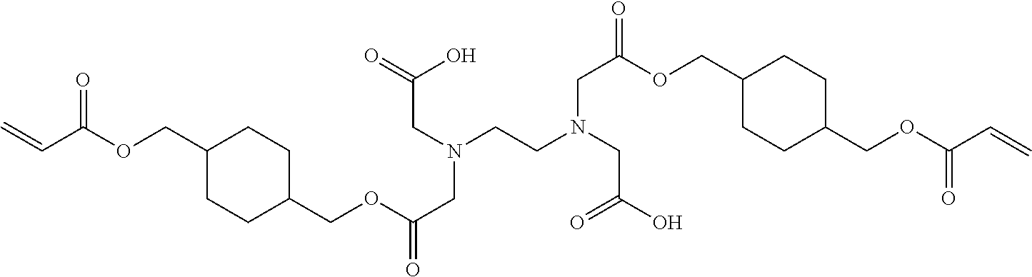 |
Mono-4 |
 |
Mono-5 |
 |
Mono-6 |
 |
Mono-7 |
| TABLE 2 | |
|
|
AA-1 |
 |
AA-2 |
 |
AA-3 |
 |
AA-4 |
 |
AA-5 |
 |
AA-6 |
 |
AA-7 |
 |
AA-8 |
 |
AA-9 |
 |
AA-10 |
-
- 15 to 70 wt % of an acryl amide as described above;
- 20 to 75 wt % of a di- or polyfunctional acrylate as described above; and
- 1 to 15 wt % of the adhesion promoter as described above.
-
- statistically polymerized monomers (e.g. monomers A and B polymerized into ABBAABAB);
- alternating polymerized monomers (e.g. monomers A and B polymerized into ABABABAB);
- gradient (tapered) polymerized monomers (e.g. monomers A and B polymerized into AAABAABBABBB);
- block copolymers (e.g. monomers A and B polymerized into AAAAABBBBBB) wherein the block length of each of the blocks (2, 3, 4, 5 or even more) is important for the dispersion capability of the polymeric dispersant;
- graft copolymers (graft copolymers consist of a polymeric backbone with polymeric side chains attached to the backbone); and
- mixed forms of these polymers, e.g. blocky gradient copolymers.
-
- DISPERBYK™ dispersants available from BYK CHEMIE GMBH;
- SOLSPERSE™ dispersants available from NOVEON;
- TEGO™ DISPERS™ dispersants from EVONIK;
- EDAPLAN™ dispersants from MÜNZING CHEMIE;
- ETHACRYL™ dispersants from LYONDELL;
- GANEX™ dispersants from ISP;
- DISPEX™ and EFKA™ dispersants from CIBA SPECIALTY CHEMICALS INC;
- DISPONER™ dispersants from DEUCHEM; and
- JONCRYL™ dispersants from JOHNSON POLYMER.
-
- a) forming a protected area on a metal or glass surface by printing and curing a radiation curable inkjet ink as described above on the metal surface;
- b) removing metal or glass from an unprotected area of the metal or glass surface by etching; and
- c) removing at least partially the cured radiation curable inkjet ink from the protected area of the metal or glass surface.
-
- UV-A: 400 nm to 320 nm
- UV-B: 320 nm to 290 nm
- UV-C: 290 nm to 100 nm.


| TABLE 3 | |||
| Component | wt % | ||
| DPGDA | 82.4 | ||
| p-methoxyphenol | 4.0 | ||
| 2,6-di-tert-butyl-4-methylphenol | 10.0 | ||
| Cupferron ™ AL | 3.6 | ||
| TABLE 4 | ||||||
| wt % of | ||||||
| component | COMP-1 | COMP-2 | COMP-3 | COMP-4 | COMP-5 | INV-1 |
| SR606 | 40 | 40 | 40 | 40 | 40 | 40 |
| ACMO | 36 | 36 | 36 | 36 | 36 | 36 |
| ITX | 4 | 4 | 4 | 4 | 4 | 4 |
| TPO | 4 | 4 | 4 | 4 | 4 | 4 |
| EPD | 4 | 4 | 4 | 4 | 4 | 4 |
| INHIB | 1 | 1 | 1 | 1 | 1 | 1 |
| DYE-1 | 1 | 1 | 1 | 1 | 1 | 1 |
| CEA | 10 | — | — | — | — | — |
| Polysurf HP | — | 10 | — | — | — | — |
| Polysurf HPACE | — | — | 10 | — | — | — |
| Polysurf HPL | — | — | — | 10 | — | — |
| Polysurf HPH | — | — | — | — | 10 | — |
| Mono-1 | — | — | — | — | — | 10 |
| TABLE 5 | ||||
| Viscosity, | Viscosity, | |||
| UV curable | fresh | 7 days 80° C. | ||
| ink jet ink | (45° C., mPas) | (45° C., mPas) | ||
| COMP-1 | 11 | 12 | ||
| COMP-2 | 12.3 | >50 | ||
| COMP-3 | 12.1 | >50 | ||
| COMP-4 | 9 | >50 | ||
| COMP-5 | 12.1 | >50 | ||
| INV-1 | 10.7 | 11.6 | ||
| TABLE 6 | ||||
| Etch resist | Wet adhesion | Wet adhesion | ||
| sample | after etching | after rinsing | ||
| COMP-S-1 | OK | nOK | ||
| COMP-S-2 | OK | nOK | ||
| COMP-S-3 | OK | nOK | ||
| COMP-S-4 | OK | nOK | ||
| COMP-S-5 | nOK | nOK | ||
| INV-1 | OK | OK | ||
| TABLE 7 | |||||
| wt % of component | COMP-6 | COMP-7 | INV-2 | ||
| SR606 | 40 | 40 | 40 | ||
| ACMO | 41 | 36 | 36 | ||
| ITX | 4 | 4 | 4 | ||
| TPO | 4 | 4 | 4 | ||
| EPD | 4 | 4 | 4 | ||
| INHIB | 1 | 1 | 1 | ||
| DYE-1 | 1 | 1 | 1 | ||
| CEA | 5 | — | — | ||
| CN146 | — | 10 | — | ||
| Mono-1 | — | — | 10 | ||
| TABLE 8 | ||||||
| UV | Wet | Wet | Wet | Wet | ||
| curable | adhesion | adhesion | % | adhesion | adhesion | % |
| ink jet | etching | rinsing | remaining | etching | rinsing | remaining |
| ink | (CuCl2) | (CuCl2) | (CuCl2) | (FeCl3) | (FeCl3) | (FeCl3) |
| COMP-6 | nOK | nOK | 15 | OK | OK | 100 |
| COMP-7 | OK | OK | 97 | OK | OK | 70 |
| INV-2 | OK | OK | 99 | OK | OK | 100 |
Claims (14)


Applications Claiming Priority (4)
| Application Number | Priority Date | Filing Date | Title |
|---|---|---|---|
| EP16188702.1 | 2016-09-14 | ||
| EP16188702 | 2016-09-14 | ||
| EP16188702.1A EP3296368B1 (en) | 2016-09-14 | 2016-09-14 | Etch-resistant inkjet inks for manufacturing printed circuit boards |
| PCT/EP2017/071968 WO2018050457A1 (en) | 2016-09-14 | 2017-09-01 | Etch-resistant inkjet inks for manufacturing printed circuit boards |
Publications (2)
| Publication Number | Publication Date |
|---|---|
| US20210277267A1 US20210277267A1 (en) | 2021-09-09 |
| US11466166B2 true US11466166B2 (en) | 2022-10-11 |
Family
ID=56926087
Family Applications (1)
| Application Number | Title | Priority Date | Filing Date |
|---|---|---|---|
| US16/332,383 Active 2040-01-12 US11466166B2 (en) | 2016-09-14 | 2017-09-01 | Etch-resistant inkjet inks for manufacturing printed circuit boards |
Country Status (6)
| Country | Link |
|---|---|
| US (1) | US11466166B2 (en) |
| EP (1) | EP3296368B1 (en) |
| JP (1) | JP6828143B2 (en) |
| KR (1) | KR102254841B1 (en) |
| CN (1) | CN109689803B (en) |
| WO (1) | WO2018050457A1 (en) |
Families Citing this family (6)
| Publication number | Priority date | Publication date | Assignee | Title |
|---|---|---|---|---|
| DE102019113960A1 (en) * | 2019-03-29 | 2020-10-01 | Pierce Protocols Limited | Process and system for glass etching preparation |
| EP3757174B1 (en) * | 2019-06-28 | 2022-04-20 | Agfa-Gevaert Nv | Radiation curable inkjet ink for alkaline etching or plating applications |
| KR20220127272A (en) * | 2020-01-13 | 2022-09-19 | 카티바, 인크. | inkjet printed circuit board |
| US12264249B2 (en) | 2020-10-20 | 2025-04-01 | Microcosm Technology Co., Ltd. | Curable composition for inkjet, cured product and flexible printed circuit board |
| TWI748695B (en) * | 2020-10-20 | 2021-12-01 | 律勝科技股份有限公司 | Curable composition for inkjet, cured product and flexible printed circuit board |
| US11597781B2 (en) | 2020-12-29 | 2023-03-07 | Canon Kabushiki Kaisha | Photocurable composition for making layers with high etch resistance |
Citations (13)
| Publication number | Priority date | Publication date | Assignee | Title |
|---|---|---|---|---|
| US4424095A (en) * | 1981-01-12 | 1984-01-03 | Kollmorgen Technologies Corporation | Radiation stress relieving of polymer articles |
| US4529477A (en) * | 1983-05-02 | 1985-07-16 | Kollmorgen Technologies Corporation | Process for the manufacture of printed circuit boards |
| US5770637A (en) * | 1996-05-01 | 1998-06-23 | Johnson & Johnson Vision Products, Inc. | Anti-bacterial, UV absorbable, tinted, metal-chelating polymers |
| WO2004026977A1 (en) | 2002-09-20 | 2004-04-01 | Avecia Limited | Process and ink for making electronic devices |
| WO2004106437A1 (en) | 2003-05-30 | 2004-12-09 | Avecia Inkjet Limited | Process |
| US6849308B1 (en) * | 1999-05-27 | 2005-02-01 | Stuart Speakman | Method of forming a masking pattern on a surface |
| US20060019077A1 (en) * | 2004-07-02 | 2006-01-26 | Avecia Inkjet Limited | Process |
| US20060047014A1 (en) * | 2002-09-20 | 2006-03-02 | Hopper Alan J | Printing process and solder mask ink composition |
| EP1721949A1 (en) | 2005-05-13 | 2006-11-15 | VOCO GmbH | Adhesive with improved adhesive strength for polymerisable composition |
| EP2033949A1 (en) | 2007-09-04 | 2009-03-11 | Agfa Graphics N.V. | Radiation curable compositions for food applications |
| EP2065363A1 (en) | 2007-11-30 | 2009-06-03 | Ivoclar Vivadent AG | Dental materials based on alkylenediamine-N,N,N',N'-tetraacetic acid-(meth)acrylamides |
| EP2130817A1 (en) | 2008-06-05 | 2009-12-09 | AGFA Graphics NV | Polymerizable Type II photoinitiators and curable compositions |
| EP2725075A1 (en) | 2012-10-24 | 2014-04-30 | Agfa-Gevaert | Radiation curable inkjet inks |
Family Cites Families (17)
| Publication number | Priority date | Publication date | Assignee | Title |
|---|---|---|---|---|
| GB1464250A (en) * | 1973-12-27 | 1977-02-09 | Ciba Geigy Ag | Acrylate derivatives and their use as anaerobically-curing adhesives |
| JPH06122608A (en) * | 1992-06-23 | 1994-05-06 | Univ California | Dental adhesive primer and dentin pretreatment agent |
| US5514732A (en) * | 1993-07-22 | 1996-05-07 | Johnson & Johnson Vision Products, Inc. | Anti-bacterial, insoluble, metal-chelating polymers |
| US7018455B2 (en) * | 2001-03-30 | 2006-03-28 | Seiko Epson Corporation | Ink composition, recording medium, ink jet recording method, and printed matter |
| JP4783151B2 (en) * | 2003-12-19 | 2011-09-28 | クラレメディカル株式会社 | One-part dental adhesive composition |
| KR100733920B1 (en) | 2004-09-17 | 2007-07-02 | 주식회사 엘지화학 | Ink composition for etching resist, etching resist pattern formation method and fine flow path formation method using same |
| JP4738013B2 (en) | 2005-02-16 | 2011-08-03 | 富士フイルム株式会社 | Ink for ink jet recording and method for producing planographic printing plate using the same |
| PL2740773T3 (en) | 2006-10-11 | 2019-05-31 | Agfa Nv | Curable pigment inkjet ink sets and methods for preparing the said ink sets |
| EP1935652B1 (en) | 2006-12-21 | 2010-04-21 | Agfa Graphics N.V. | Inkjet Printing methods and ink sets |
| DE602007014219D1 (en) | 2007-10-24 | 2011-06-09 | Agfa Graphics Nv | Curable liquids and inks for toys and food packaging |
| EP2065362A1 (en) | 2007-11-29 | 2009-06-03 | Agfa Graphics N.V. | Preparation method of copolymerizable photoinitiators |
| JP5457636B2 (en) * | 2008-01-22 | 2014-04-02 | 富士フイルム株式会社 | Photocurable composition, photocurable ink composition, method for producing photocured product, and inkjet recording method |
| JP2010008780A (en) * | 2008-06-27 | 2010-01-14 | Fujifilm Corp | Photopolymerizable composition, color filter and method for manufacturing the same, solid-state image pickup device and lithographic printing plate precursor |
| KR101472869B1 (en) * | 2008-04-28 | 2014-12-15 | 후지필름 가부시키가이샤 | Photopolymerizable composition, photopolymerizable composition for color filter, color filter, method of manufacturing the same, solid-state imaging device, and planographic printing plate precursors |
| US8569393B2 (en) | 2009-12-07 | 2013-10-29 | Agfa-Gevaert N.V. | UV-LED curable compositions and inks |
| JP5602195B2 (en) * | 2011-09-27 | 2014-10-08 | 富士フイルム株式会社 | Planographic printing plate precursor and lithographic printing plate preparation method |
| BE1020757A3 (en) | 2012-06-19 | 2014-04-01 | Agc Glass Europe | METHOD FOR MANUFACTURING A SELECTIVELY POLISHED GLASS SHEET |
-
2016
- 2016-09-14 EP EP16188702.1A patent/EP3296368B1/en not_active Not-in-force
-
2017
- 2017-09-01 WO PCT/EP2017/071968 patent/WO2018050457A1/en not_active Ceased
- 2017-09-01 JP JP2019514283A patent/JP6828143B2/en not_active Expired - Fee Related
- 2017-09-01 US US16/332,383 patent/US11466166B2/en active Active
- 2017-09-01 CN CN201780056564.9A patent/CN109689803B/en not_active Expired - Fee Related
- 2017-09-01 KR KR1020197007497A patent/KR102254841B1/en not_active Expired - Fee Related
Patent Citations (14)
| Publication number | Priority date | Publication date | Assignee | Title |
|---|---|---|---|---|
| US4424095A (en) * | 1981-01-12 | 1984-01-03 | Kollmorgen Technologies Corporation | Radiation stress relieving of polymer articles |
| US4529477A (en) * | 1983-05-02 | 1985-07-16 | Kollmorgen Technologies Corporation | Process for the manufacture of printed circuit boards |
| US5770637A (en) * | 1996-05-01 | 1998-06-23 | Johnson & Johnson Vision Products, Inc. | Anti-bacterial, UV absorbable, tinted, metal-chelating polymers |
| US6849308B1 (en) * | 1999-05-27 | 2005-02-01 | Stuart Speakman | Method of forming a masking pattern on a surface |
| US20060047014A1 (en) * | 2002-09-20 | 2006-03-02 | Hopper Alan J | Printing process and solder mask ink composition |
| WO2004026977A1 (en) | 2002-09-20 | 2004-04-01 | Avecia Limited | Process and ink for making electronic devices |
| WO2004106437A1 (en) | 2003-05-30 | 2004-12-09 | Avecia Inkjet Limited | Process |
| US20060019077A1 (en) * | 2004-07-02 | 2006-01-26 | Avecia Inkjet Limited | Process |
| EP1721949A1 (en) | 2005-05-13 | 2006-11-15 | VOCO GmbH | Adhesive with improved adhesive strength for polymerisable composition |
| EP2033949A1 (en) | 2007-09-04 | 2009-03-11 | Agfa Graphics N.V. | Radiation curable compositions for food applications |
| EP2065363A1 (en) | 2007-11-30 | 2009-06-03 | Ivoclar Vivadent AG | Dental materials based on alkylenediamine-N,N,N',N'-tetraacetic acid-(meth)acrylamides |
| US20090139433A1 (en) | 2007-11-30 | 2009-06-04 | Ivoclar Vivadent Ag | Dental materials based on alkylenediamine-n,n,n',n'- tetraacetic acid- (meth)acrylamides |
| EP2130817A1 (en) | 2008-06-05 | 2009-12-09 | AGFA Graphics NV | Polymerizable Type II photoinitiators and curable compositions |
| EP2725075A1 (en) | 2012-10-24 | 2014-04-30 | Agfa-Gevaert | Radiation curable inkjet inks |
Non-Patent Citations (1)
| Title |
|---|
| Official Communication issued in International Patent Application No. PCT/EP2017/071968, dated Oct. 16, 2017. |
Also Published As
| Publication number | Publication date |
|---|---|
| JP2019534909A (en) | 2019-12-05 |
| CN109689803A (en) | 2019-04-26 |
| WO2018050457A1 (en) | 2018-03-22 |
| EP3296368B1 (en) | 2020-11-11 |
| JP6828143B2 (en) | 2021-02-10 |
| KR20190040255A (en) | 2019-04-17 |
| US20210277267A1 (en) | 2021-09-09 |
| KR102254841B1 (en) | 2021-05-25 |
| EP3296368A1 (en) | 2018-03-21 |
| CN109689803B (en) | 2022-03-01 |
Similar Documents
| Publication | Publication Date | Title |
|---|---|---|
| EP3000853B1 (en) | Etch-resistant inkjet inks for manufacturing conductive patterns | |
| US9556349B2 (en) | Radiation curable etch resistant inkjet ink printing | |
| US11466166B2 (en) | Etch-resistant inkjet inks for manufacturing printed circuit boards | |
| US10995229B2 (en) | Solder mask inkjet inks for manufacturing printed circuit boards | |
| US10793468B2 (en) | Method of manufacturing an etched glass article | |
| US11091659B2 (en) | Solder mask inkjet inks for manufacturing printed circuit boards | |
| US10947402B2 (en) | Solder mask inkjet inks for manufacturing printed circuit boards | |
| US12421405B2 (en) | Radiation curable composition for plating applications | |
| US20220010156A1 (en) | Radiation curable inkjet ink for manufacturing printed circuit boards | |
| US11407913B2 (en) | Inkjet inks for manufacturing printed circuit boards | |
| EP3533844B1 (en) | Inkjet inks for manufacturing printed circuit boards | |
| US20250234462A1 (en) | Method of Plating a Printed Circuit Board | |
| US20230159779A1 (en) | Method of Manufacturing Printed Circuit Boards |
Legal Events
| Date | Code | Title | Description |
|---|---|---|---|
| AS | Assignment |
Owner name: AGFA-GEVAERT NV, BELGIUM Free format text: ASSIGNMENT OF ASSIGNORS INTEREST;ASSIGNORS:LOCCUFIER, JOHAN;TORFS, RITA;SIGNING DATES FROM 20190115 TO 20190121;REEL/FRAME:048568/0722 |
|
| FEPP | Fee payment procedure |
Free format text: ENTITY STATUS SET TO UNDISCOUNTED (ORIGINAL EVENT CODE: BIG.); ENTITY STATUS OF PATENT OWNER: LARGE ENTITY |
|
| STPP | Information on status: patent application and granting procedure in general |
Free format text: DOCKETED NEW CASE - READY FOR EXAMINATION |
|
| STPP | Information on status: patent application and granting procedure in general |
Free format text: NON FINAL ACTION MAILED |
|
| STPP | Information on status: patent application and granting procedure in general |
Free format text: RESPONSE TO NON-FINAL OFFICE ACTION ENTERED AND FORWARDED TO EXAMINER |
|
| STPP | Information on status: patent application and granting procedure in general |
Free format text: NOTICE OF ALLOWANCE MAILED -- APPLICATION RECEIVED IN OFFICE OF PUBLICATIONS |
|
| STPP | Information on status: patent application and granting procedure in general |
Free format text: PUBLICATIONS -- ISSUE FEE PAYMENT VERIFIED |
|
| STCF | Information on status: patent grant |
Free format text: PATENTED CASE |