US11461349B2 - Data filtering utilizing constructed graph structure - Google Patents
Data filtering utilizing constructed graph structure Download PDFInfo
- Publication number
- US11461349B2 US11461349B2 US16/864,785 US202016864785A US11461349B2 US 11461349 B2 US11461349 B2 US 11461349B2 US 202016864785 A US202016864785 A US 202016864785A US 11461349 B2 US11461349 B2 US 11461349B2
- Authority
- US
- United States
- Prior art keywords
- bootstrapped
- graph structure
- database
- semantic information
- parameter
- Prior art date
- Legal status (The legal status is an assumption and is not a legal conclusion. Google has not performed a legal analysis and makes no representation as to the accuracy of the status listed.)
- Active, expires
Links
Images




Classifications
-
- G—PHYSICS
- G06—COMPUTING OR CALCULATING; COUNTING
- G06F—ELECTRIC DIGITAL DATA PROCESSING
- G06F16/00—Information retrieval; Database structures therefor; File system structures therefor
- G06F16/20—Information retrieval; Database structures therefor; File system structures therefor of structured data, e.g. relational data
- G06F16/24—Querying
- G06F16/245—Query processing
-
- G—PHYSICS
- G06—COMPUTING OR CALCULATING; COUNTING
- G06F—ELECTRIC DIGITAL DATA PROCESSING
- G06F16/00—Information retrieval; Database structures therefor; File system structures therefor
- G06F16/20—Information retrieval; Database structures therefor; File system structures therefor of structured data, e.g. relational data
- G06F16/24—Querying
- G06F16/248—Presentation of query results
-
- G—PHYSICS
- G06—COMPUTING OR CALCULATING; COUNTING
- G06F—ELECTRIC DIGITAL DATA PROCESSING
- G06F16/00—Information retrieval; Database structures therefor; File system structures therefor
- G06F16/20—Information retrieval; Database structures therefor; File system structures therefor of structured data, e.g. relational data
- G06F16/21—Design, administration or maintenance of databases
- G06F16/211—Schema design and management
- G06F16/212—Schema design and management with details for data modelling support
-
- G—PHYSICS
- G06—COMPUTING OR CALCULATING; COUNTING
- G06F—ELECTRIC DIGITAL DATA PROCESSING
- G06F16/00—Information retrieval; Database structures therefor; File system structures therefor
- G06F16/20—Information retrieval; Database structures therefor; File system structures therefor of structured data, e.g. relational data
- G06F16/28—Databases characterised by their database models, e.g. relational or object models
- G06F16/284—Relational databases
- G06F16/288—Entity relationship models
-
- G—PHYSICS
- G06—COMPUTING OR CALCULATING; COUNTING
- G06F—ELECTRIC DIGITAL DATA PROCESSING
- G06F16/00—Information retrieval; Database structures therefor; File system structures therefor
- G06F16/90—Details of database functions independent of the retrieved data types
- G06F16/901—Indexing; Data structures therefor; Storage structures
- G06F16/9024—Graphs; Linked lists
Definitions
- the reliability engineer may in turn provide instructions to one or more work center expert(s) dedicated to a particular worksite.
- the skill set and institutional knowledge of that work center expert may be more specialized, reflecting the narrower focus of his or her vocational duties.
- Still other individuals may be responsible for planning operation of the complex system. Such planners may focus upon larger issues of supply chain management of essential components, and forecasting demands expected to be made upon the system in the near term, or the projected future.
- Embodiments relate to (global, lateral) data filtering techniques which may be employed alone or in combination.
- a global filter allows data filtering using attributes of a data object across multiple Analysis Tools (ATs), through the broadcast of semantic filter context objects.
- ATs Analysis Tools
- the filter context object with attribute data is created with attribute names and values.
- the filter context object is then resolved into a data object, and subsequently into target data by a processing engine. Passing the filter context object (rather than already-resolved Entity IDs) to the processing engine, reduces the payload and renders communication between services fast and efficient.
- a lateral filter finds related entities in a relational database, without having to maintain and/or duplicate all of the data into a graph database.
- the processing engine resolves lateral filters using an entity graph path calculation performed in conjunction with the generation of a graph structure bootstrapped from available information.
- the bootstrapped graph structure is constructed utilizing available semantic data regarding database schematics (schemantics). These may be a combination of pre-calculated—e.g., Primary Key (PK)/Foreign Key (FK)—relations between database tables, as well as other metadata read from the relational database. From that information, relationships in the bootstrapped graph structure are created. Possible paths taken between entities in the bootstrapped graph structure are used to generate an optimized SQL, query to reach the target data.
- the bootstrapped graph can change dynamically based upon received schemantics, thereby desirably reducing a size of the bootstrapped graph structure. Such a dynamic nature can be particularly beneficial when the bootstrapped graph structure spans multiple databases.
- FIG. 1 shows a simplified diagram of a system according to an embodiment.
- FIG. 2 shows a simplified flow diagram of a method according to an embodiment.
- FIG. 3 depicts an architecture of an exemplary embodiment.
- FIG. 4 shows a sequence diagram of a global filter according to the example.
- FIG. 5 shows a simplified view of a graph structure representing tables of different databases.
- FIG. 6 shows a simplified view of the dynamic creation of a graph structure utilized in lateral filtering according to the example.
- FIG. 7 shows a sequence diagram of a lateral filter according to the example.
- FIG. 8 shows an example of a semantic context filter object with attribute data.
- FIG. 9 shows an example of pre-calculated relationships.
- FIG. 10 shows an example of a payload lateral filter with global filter applied.
- FIG. 11 shows an example of a graph representation in memory.
- FIG. 12 shows an example of a payload lateral filter without global filter applied.
- FIG. 13 shows an example of service registration with scope information.
- FIGS. 14A-E show simplified screen shots of an interface for one use case.
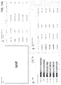
- FIGS. 15A-E show simplified screen shots of an interface for another use case.
- FIG. 16 illustrates hardware of a special purpose computing machine according to an embodiment that is configured to implement data filtering utilizing a graph structure.
- FIG. 17 illustrates an example computer system.
- FIG. 1 shows a simplified view of system that is configured to implement data filtering according to an embodiment.
- system 100 comprises a filtering application 102 that is in communication with a SQL compliant database 104 that is located on a server side 106 .
- the processing engine 108 of the application receives from a user 110 , an input 112 regarding filtering of the data. This input is received at an Application Program Interface (API) 116 .
- API Application Program Interface
- the user instruction prompts a global filtering operation.
- the global filter allows the user to filter data using Business Object attributes across multiple analysis tools by passing semantic filter context objects.
- the global filter component 118 of the engine constructs a filter context object 120 with attribute names and values. This context object is then broadcast to all Analysis Tools, including the Master Analysis Tool 122 .
- the master AT then passes 123 the context object from master AT back to the engine. Based upon the attribute information in the context object, the engine issues a query 124 to the database, and receives in return target data in the form of a query result 126 .
- the engine may also make calls 130 (e.g., OData) to collect data from other databases 131 , for example those referenced in connection with microservices.
- the result 132 of those calls is considered in performing the database querying operation.
- the output 134 of the global filtering is communicated back to the user. This may be done by displaying the global filtering results on a screen 136 , for example on the left hand side.
- the user instruction prompts a lateral filtering operation.
- the lateral filter finds related entities in a relational database, without the cost of maintaining and duplicating all (voluminous) data into a graph database.
- the engine is configured to receive semantic information 140 regarding the schema of the database.
- This information can comprise pre-calculated relationships such as PK/FK linking tables of the database, as well as other metadata descriptive of the structure of the database.
- the processing engine resolves lateral filters using an entity graph path calculation that is conducted in conjunction with the generation of a bootstrapped graph structure 150 .
- the graph structure is constructed in a bootstrapped manner by a graph creation component 151 , utilizing the available schematic information stored as graph data 152 in an underlying database 154 .
- a query formulation component 156 creates relationships in the bootstrapped graph structure. These relationships form the basis for the lateral filtering operation.
- local filter criteria 158 are passed from the Master AT to a Dependent AT 160 .
- the Dependent AT in turn communicates as input 162 to the processing engine, the parameter information including a payload 164 .
- the query formulation component uses possible paths taken between entities to generate an optimized SQL query 124 to reach the target data.
- OData calls and results may also be made by the processing engine (e.g., as in the case of microservices).
- the bootstrapped graph can change dynamically based upon received schemantics (DB schema semantics).
- the bootstrapped data structure can desirably reduce a size of the bootstrapped graph structure.
- Such a dynamic nature of the graph structure can be particularly beneficial when the bootstrapped graph structure spans multiple databases.
- the output 170 of the lateral filtering is communicated back to the user. For ease of user recognition, this may be done by consistently displaying the lateral filtering results on a different part of the API screen—e.g., the right hand (R) portion of the screen as in the exemplary screen shots given below).
- R right hand
- FIG. 2 is a simplified flow diagram of a method 200 according to an embodiment.
- a filter criteria is received from a first analysis tool, the filter criteria including an attribute of a data corpus stored in a database according to a schema.
- semantic information is received from the database, the semantic information describing a hierarchy of the schema organized according to an attribute level and a parameter level.
- the filter criteria and the semantic information are referenced construct a bootstrapped graph structure comprising entities and relationships.
- an input is received from a second analysis tool, the input comprising a payload including a parameter.
- the bootstrapped graph structure and the input are referenced to calculate paths between entities and relationships and generate a SQL query including the parameter.
- the SQL query is resolved against the database.
- a corresponding query result including the parameter is received from the database.
- the corresponding query result is displayed to a screen of an interface.
- SAP SE of Walldorf, Germany offers a suite of different data analytics applications that are available for different types of data.
- SCM Supply Chain Management
- IAM Intelligent Asset Management
- SAP has developed the WORKBENCH application, which allow users to perform tasks using integrated data views.
- WORKBENCH can be customized and extended as per user needs, to assist in monitoring, exploring data views, creating evidence packages, and taking actions accordingly.
- FIG. 3 depicts a simplified view of the architecture 300 of this exemplary embodiment.
- the WORKBENCH includes an infrastructure that allows data filtering to be carried out in two ways: ⁇ global filtering, and ⁇ lateral filtering.
- Global filtering is shown by the global filter module 302 supplying global filter criteria 304 to the Master Analysis Tool (AT).
- a global filter bar of the global filter monitor includes fields such as Equipment (E), Model (M), Location (L), and their respective attributes. These can include custom attributes created by customer, as well as standard fields such as Class, Subclass and System.
- Lateral filtering occurs from the Master AT to a Dependent AT. Lateral filtering will allow for filtering based on (E, M, L) IDs, and highlighting records on the right of a display screen, with a relationship shown on the left of the display screen. Exemplary screen shots are described later below.
- Central Service 306 maintains information regarding at least the following.
- a second prerequisite is that every AT has an OData Endpoint to retrieve the required data based on object IDs.
- a third prerequisite is that the Central Service has direct access to DB tables (read-only).
- the Global Filter allows the user to filter data using Business Object attributes across all analysis tools, by passing semantic filter context objects.
- the Global Filter module utilizes the Asset Central (AC) search engine module which uses an inverted index data structure to store business object data.
- This data ingestion takes place on creation, update, and deletion of business object instances in real time using separate KAFKA topics for each entity.
- This data store contains business object data in the form of normalized JSON document which are also enriched with user defined attributes. The attributes and their values are available for querying in Global Filter toolbar through the Search Engine module.
- the inverted index data structure facilitates fast and efficient free text querying across the normalized document records.
- the attribute query from the Global Filter toolbar is broadcast to all analysis tools in the form of a semantic context filter object through Context Broadcasting.
- FIG. 8 shows an example of a semantic context filter object with attribute data.
- This filter object is resolved to business object ID. Then it is subsequently resolved to target data by the Central Service.
- FIG. 10 shows an example of a payload of a lateral filter with global filter applied.
- FIG. 10 may be contrasted with FIG. 12 , which shows an example of a payload of a lateral filter without global filter applied.
- the smaller payload results in fast and efficient communication taking place between services.
- Central Service communicates with the AC Search Engine module to resolve the context object to business object/Entity IDs. This information is then subsequently used to obtain target data.
- This particular example shows the AC search engine operating on the AC Hana in-memory database storage platform.
- FIG. 4 shows a sequence diagram of a global filter according to the example.
- the Lateral Filter finds related entities in a relational database without the need of maintaining and duplicating all data into a Graph Database.
- the processing engine that finds related entities according to lateral filtering is based on an in-memory, loose, unweighted, and undirected graph.
- the graph represents the relationship of entities in a relational database and it can span multiple relational databases (e.g., a mesh structure).
- the graph structure is dynamically bootstrapped using a combination of pre-calculated relations.
- FIG. 9 shows an example of pre-calculated relationships according to this example.
- the bootstrapped graph structure is based on the metadata read from the relational database. That metadata defines how tables are linked with each other based on Primary Keys and Foreign Keys. Based upon this information, relationships are built.
- Bootstrapping of the graph can happen dynamically.
- Such dynamic creation can be based upon the received input database schema semantics (schemantics) in order to further reduce graph size. This is especially beneficial when the graph spans multiple databases.
- FIG. 5 reflects the schemas of the databases of three (3) different SAP products that are relevant to asset management:
- embodiments Based on the received input semantics and the bootstrapped graph, embodiments utilize different pathfinding procedures to find relationships between entities.
- a particular embodiment may utilize Dijkstra's algorithm for this purpose, but other procedures can be used that are able to handle a graph that contains circles.
- This particular example may employ the following optimizations.
- FIG. 6 shows the original bootstrapped graph structure 600 . Based on the input semantics we can remove the area 602 from the graph, since that part of the graph is needed to find related data.
- FIG. 11 shows an example of a graph representation in memory. Once those paths are identified, a SQL Statement will be built dynamically.
- the embodiment according to this example may allow for the enriching of information.
- Such data enrichment may be useful in that not all information is stored in the relational database, and also some properties might be calculated on the fly.
- WORKBENCH supports enriching the information returned from the database by doing additional API calls.
- the required API calls are part of the input schematics.
- the specified. URL endpoint will be queried with the returned Ids from the database.
- Information returned from those API calls will be blended in our service with data from the database before everything gets bundled into a ResultSet and sent to the client.
- FIG. 7 shows a sequence diagram of a lateral filter according to the example.
- the OData Services used in the ATs and the Central Services internally use to user's authentication token to only return the data the user is authorized to view.
- the ATs limit actions available to the user, if the authorization token does not contain scopes defined in the service entry of the AT.
- the WORKBENCH embodiment according to this example supports the SAP Asset Intelligence Network (AIN) sharing mechanism. Specifically, a customer can invite a partner to view and perform actions upon asset data in WORKBENCH.
- SAP Asset Intelligence Network AIN
- the services used in WORKBENCH internally use Access Control List tables containing access data for each Entity. These are checked against the User authentication token to return data that an authorized partner is approved to access.
- Service registration and discovery is available according to this example. Specifically, WORKBENCH uses Service Catalog to add and remove ATs from a user's workspace, which contains service registration information for each tool.
- This service registration information is provided at the time of deployment by the AT, and it includes scope related information.
- FIG. 13 shows an example of service registration with scope information.
- An AT is available in the Service Catalog for a User if their authentication token contains the scope for that specific tool.
- a work package can be assigned to other business objects.
- the work package can be used in follow-up processes, including but not limited to: creating improvement requests, notifications, or work orders.
- Follow-up processes can relate to items in a work package and not to the package itself.
- Packages may also contain historical information, such as at time when a business object was added to the package, and any follow-up processes initiated related to the package.
- work packages While any user can create work packages, only those users with configuration access can view and process all the work packages in the system for a particular tenant.
- work packages could also arise in other applications (such as other masterdata applications like assessments). Work packages can also be further enhanced in other applications, before finally being processed in a package management application.
- FIGS. 14A-E show simplified screen shots of an interface for one use case in an asset management environment.
- the user is a maintenance engineer who seeks to determine how assets (e.g., pumps) are performing.
- assets e.g., pumps
- the maintenance engineer's home page is shown in FIG. 14A , which offers an overview regarding the current behavior of the assets.
- his home page allows the user to focus on the most important tasks of the day and react on the information quickly.
- FIG. 14A shows a simplified view of the screen resulting from user selection of an Equipment Condition parameter. This screen offers detailed information regarding various pump assets.
- FIG. 14B shows a simplified view of the screen resulting from user selection of an ⁇ Equipment Condition parameter (represented by icon 1400 ). This screen offers detailed information regarding various pump assets.
- FIG. 14C shows the screen resulting from a user selecting a different parameter icon 1402 in FIG. 14B .
- the screen displays information regarding the ⁇ Alert parameter.
- FIG. 14D shows the screen resulting from a user selecting the Explore button of the screen of FIG. 14B . This results in the left/right screen configuration, with the left screen showing the ⁇ Equipment Condition parameter information, and the right screen showing the results of lateral filtering of that parameter data according to a ⁇ Map sub-parameter.
- FIG. 14E shows the screen resulting from a user selecting instead the tab for the ⁇ Alert sub-parameter for the ⁇ Equipment Condition parameter.
- the lateral filtering results are shown in a map display on the right hand side of the screen.
- FIGS. 15A-E show simplified screen shots of an interface for another use case in an asset management environment.
- the user is a maintenance planner, who seeks to inspect maintenance strategies for the (pump) assets.
- the maintenance planner's home page is shown in FIG. 15A , which offers an overview regarding the assets.
- his home page allows the user to focus upon the most urgent planning activities.
- the ⁇ Maintenance Monitor parameter (shown by the icon 1500 ) is a good place to start, because it affords the user direct access to assets demanding attention.
- FIG. 15C shows the ⁇ Maintenance Monitor parameter information displayed as a network graph instead.
- FIG. 15D shows the result screen, where the left half of the screen comprises the ⁇ Maintenance Monitor parameter, and the right half of the screen shows filtering results from the ⁇ Recommendation sub-parameter.
- the screen of FIG. 15E shows the result of the user selecting the tab for the ⁇ Context Information instead.
- the resulting lateral filtering on the right hand side provides details regarding the context of the asset shown on the left hand side of the screen.
- FIG. 1 there the particular embodiment is depicted with the engine responsible for data filtering as being located outside of the database storing the graph data. However, this is not required.
- an in-memory database engine e.g., the in-memory database engine of the HANA in-memory database available from SAP SE, in order to perform various functions.
- FIG. 16 illustrates hardware of a special purpose computing machine configured to implement content sharing according to an embodiment.
- computer system 1601 comprises a processor 1602 that is in electronic communication with a non-transitory computer-readable storage medium comprising a database 1603 .
- This computer-readable storage medium has stored thereon code 1605 corresponding to an engine.
- Code 1604 corresponds to graph data.
- Code may be configured to reference data stored in a database of a non-transitory computer-readable storage medium, for example as may be present locally or in a remote database server.
- Software servers together may form a cluster or logical network of computer systems programmed with software programs that communicate with each other and work together in order to process requests.
- Embodiments as described herein may offer certain benefits over other approaches.
- embodiments may bring together the data the user needs to perform the task in a modular, adaptable fashion, avoiding duplication of information.
- the user can extend the platform as per their needs by utilizing the various customizable options and the efficient user experience.
- Embodiments may also offer a modular workspace which can be customized by adding independent analysis tools with their configured variants, to visualize and compare data in order to perform detailed explorative analysis.
- the underlying filtering infrastructure allows users to quickly slice-and-dice data across various business objects and dimensions, and perform comparative analysis. Relevant artifacts can be packaged together and shared with other users to plan routines (e.g., maintenance) and to recommend further actions.
- Computer system 1710 includes a bus 1705 or other communication mechanism for communicating information, and a processor 1701 coupled with bus 1705 for processing information.
- Computer system 1710 also includes a memory 1702 coupled to bus 1705 for storing information and instructions to be executed by processor 1701 , including information and instructions for performing the techniques described above, for example.
- This memory may also be used for storing variables or other intermediate information during execution of instructions to be executed by processor 1701 . Possible implementations of this memory may be, but are not limited to, random access memory (RAM), read only memory (ROM), or both.
- a storage device 1703 is also provided for storing information and instructions.
- Storage devices include, for example, a hard drive, a magnetic disk, an optical disk, a CD-ROM, a DVD, a flash memory, a USB memory card, or any other medium from which a computer can read.
- Storage device 1703 may include source code, binary code, or software files for performing the techniques above, for example.
- Storage device and memory are both examples of computer readable mediums.
- Computer system 1710 may be coupled via bus 1705 to a display 1712 , such as a cathode ray tube (CRT) or liquid crystal display (LCD), for displaying information to a computer user.
- a display 1712 such as a cathode ray tube (CRT) or liquid crystal display (LCD)
- An input device 1711 such as a keyboard and/or mouse is coupled to bus 1705 for communicating information and command selections from the user to processor 1701 .
- the combination of these components allows the user to communicate with the system.
- bus 1705 may be divided into multiple specialized buses.
- Computer system 1710 also includes a network interface 1704 coupled with bus 1705 .
- Network interface 1704 may provide two-way data communication between computer system 1710 and the local network 1720 .
- the network interface 1704 may be a digital subscriber line (DSL) or a modem to provide data communication connection over a telephone line, for example.
- DSL digital subscriber line
- Another example of the network interface is a local area network (LAN) card to provide a data communication connection to a compatible LAN.
- LAN local area network
- Wireless links are another example.
- network interface 1704 sends and receives electrical, electromagnetic, or optical signals that carry digital data streams representing various types of information.
- Computer system 1710 can send and receive information, including messages or other interface actions, through the network interface 1704 across a local network 1720 , an Intranet, or the Internet 1730 .
- computer system 1710 may communicate with a plurality of other computer machines, such as server 1715 .
- server 1715 may form a cloud computing network, which may be programmed with processes described herein.
- software components or services may reside on multiple different computer systems 1710 or servers 1731 - 1735 across the network.
- the processes described above may be implemented on one or more servers, for example.
- a server 1731 may transmit actions or messages from one component, through Internet 1730 , local network 1720 , and network interface 1704 to a component on computer system 1710 .
- the software components and processes described above may be implemented on any computer system and send and/or receive information across a network, for example.
Landscapes
- Engineering & Computer Science (AREA)
- Theoretical Computer Science (AREA)
- Databases & Information Systems (AREA)
- Data Mining & Analysis (AREA)
- Physics & Mathematics (AREA)
- General Engineering & Computer Science (AREA)
- General Physics & Mathematics (AREA)
- Software Systems (AREA)
- Computational Linguistics (AREA)
- Information Retrieval, Db Structures And Fs Structures Therefor (AREA)
Abstract
Description
- Business Objects and their aliases as Vertices data
- Primary Key—Foreign Key relationships between any two business objects as Edge data
- Lists of Equipment, Model and Location-related attributes and related Hana table
- Lists of Tables for Equipment, Model and Location business Objects where Custom Attributes and their data are stored
- 1. Global Filter context object is passed from filter bar to all ATs, which in turn passes it to Central Service along with the target object type, OData URL which can be used to get the result set, and any additional parameters.
- 2. Central Service uses the filter context object to get Entity data from the Search Engine module.
- 3. The resolved Entity data can then optionally be used to get Target Entity ID data if the Target Entity is not indexed by the Search Engine.
- 4. Central Service then makes an OData call to get Target Result Set using the Target ID data and OData URL from the first step. The result set is then passed back to requesting AT.
- 1. Each entity/table in the relational database represents a node in the graph
- 1.1 Since not every individual object's relationship is mapped but the relationship of the whole entity, the graph becomes very loose which optimizes compute time later on
- 2. Vertexes connect related entities
- 3. Since relationships are defined in both directions in a relational database, the graph is undirected
- Asset Central Database (DB Tables A1-4)
- Asset Strategy and Performance Management (ASPM) Database (DB Tables AS1-2)
- Predictive Maintenance & Service (PdMS) Database (DB Tables P1-2).
- Based upon these DB schemas, the corresponding bootstrapped graph structure is also shown in
FIG. 5 .
- 1. Not all found paths will be considered; if we only want direct relationships, we remove paths with a distance>1.
- 2. SQL Statement will be split depending on the region of the required entities since a single statement can only be executed with entities in the same database
- 3. Using SQL aliases to reduce the SQL Statement size in bytes 1.1 Example: SELECT column_name(s) FROM table_name AS alias_name;
- 1. The Master AT passes the Source IDs (Master Analysis Tool object IDs) and Source Entity Alias to the Dependent AT.
- 2. Dependent AT then sends a request to Central Service with following input semantics:
- 2.1 Source IDs
- 2.2 Source Entity Alias
- 2.3 Target Entity Alias
- 2.4 OData URL to retrieve Target Result Set based on filters
- 2.5 Any additional params for the OData Endpoint
- 3. The Central Service uses the Source and Target Alias names and saved graph data (Entity table names and their relationships) to generate an Optimized SQL Query to get Target Object IDs.
- 4. These Target Object IDs and any additional parameters provided in
Step 2, are used to get Target. ResultSet, which is then sent back to Dependent AT.
- a flat list,
- a structured view for entity hierarchies, or
- grouped by object type, class, location and more.
Claims (16)
Priority Applications (1)
| Application Number | Priority Date | Filing Date | Title |
|---|---|---|---|
| US16/864,785 US11461349B2 (en) | 2020-05-01 | 2020-05-01 | Data filtering utilizing constructed graph structure |
Applications Claiming Priority (1)
| Application Number | Priority Date | Filing Date | Title |
|---|---|---|---|
| US16/864,785 US11461349B2 (en) | 2020-05-01 | 2020-05-01 | Data filtering utilizing constructed graph structure |
Publications (2)
| Publication Number | Publication Date |
|---|---|
| US20210342336A1 US20210342336A1 (en) | 2021-11-04 |
| US11461349B2 true US11461349B2 (en) | 2022-10-04 |
Family
ID=78293730
Family Applications (1)
| Application Number | Title | Priority Date | Filing Date |
|---|---|---|---|
| US16/864,785 Active 2040-11-26 US11461349B2 (en) | 2020-05-01 | 2020-05-01 | Data filtering utilizing constructed graph structure |
Country Status (1)
| Country | Link |
|---|---|
| US (1) | US11461349B2 (en) |
Families Citing this family (1)
| Publication number | Priority date | Publication date | Assignee | Title |
|---|---|---|---|---|
| CN116882408B (en) * | 2023-09-07 | 2024-02-27 | 南方电网数字电网研究院有限公司 | Transformer diagram model construction method, device, computer equipment and storage medium |
Citations (7)
| Publication number | Priority date | Publication date | Assignee | Title |
|---|---|---|---|---|
| US20080046462A1 (en) * | 2000-10-31 | 2008-02-21 | Kaufman Michael P | System and Method for Generating Automatic User Interface for Arbitrarily Complex or Large Databases |
| US20110261049A1 (en) * | 2008-06-20 | 2011-10-27 | Business Intelligence Solutions Safe B.V. | Methods, apparatus and systems for data visualization and related applications |
| US20170006135A1 (en) * | 2015-01-23 | 2017-01-05 | C3, Inc. | Systems, methods, and devices for an enterprise internet-of-things application development platform |
| US20190050437A1 (en) * | 2017-08-10 | 2019-02-14 | Io-Tahoe Llc | Inclusion Dependency Determination In A Large Database For Establishing Primary Key-Foreign Key Relationships |
| US10452678B2 (en) * | 2013-03-15 | 2019-10-22 | Palantir Technologies Inc. | Filter chains for exploring large data sets |
| US20200026790A1 (en) * | 2017-06-22 | 2020-01-23 | Palantir Technologies Inc. | Generation and graphical display of data transform provenance metadata |
| US11030242B1 (en) * | 2018-10-15 | 2021-06-08 | Rockset, Inc. | Indexing and querying semi-structured documents using a key-value store |
-
2020
- 2020-05-01 US US16/864,785 patent/US11461349B2/en active Active
Patent Citations (7)
| Publication number | Priority date | Publication date | Assignee | Title |
|---|---|---|---|---|
| US20080046462A1 (en) * | 2000-10-31 | 2008-02-21 | Kaufman Michael P | System and Method for Generating Automatic User Interface for Arbitrarily Complex or Large Databases |
| US20110261049A1 (en) * | 2008-06-20 | 2011-10-27 | Business Intelligence Solutions Safe B.V. | Methods, apparatus and systems for data visualization and related applications |
| US10452678B2 (en) * | 2013-03-15 | 2019-10-22 | Palantir Technologies Inc. | Filter chains for exploring large data sets |
| US20170006135A1 (en) * | 2015-01-23 | 2017-01-05 | C3, Inc. | Systems, methods, and devices for an enterprise internet-of-things application development platform |
| US20200026790A1 (en) * | 2017-06-22 | 2020-01-23 | Palantir Technologies Inc. | Generation and graphical display of data transform provenance metadata |
| US20190050437A1 (en) * | 2017-08-10 | 2019-02-14 | Io-Tahoe Llc | Inclusion Dependency Determination In A Large Database For Establishing Primary Key-Foreign Key Relationships |
| US11030242B1 (en) * | 2018-10-15 | 2021-06-08 | Rockset, Inc. | Indexing and querying semi-structured documents using a key-value store |
Also Published As
| Publication number | Publication date |
|---|---|
| US20210342336A1 (en) | 2021-11-04 |
Similar Documents
| Publication | Publication Date | Title |
|---|---|---|
| US10452639B2 (en) | Processing joins in a database system using zero data records | |
| US7716233B2 (en) | System and method for processing queries for combined hierarchical dimensions | |
| US6799174B2 (en) | Retrieving, organizing, and utilizing networked data using databases | |
| Schlesinger et al. | Self-service business intelligence resulting in disruptive technology | |
| US5630127A (en) | Program storage device and computer program product for managing an event driven management information system with rule-based application structure stored in a relational database | |
| US20250165883A1 (en) | Method for dynamic model-based project benchmarking, planning, and forecasting | |
| US8943087B2 (en) | Processing data from diverse databases | |
| US7953722B2 (en) | Query response service for business objects | |
| US20170075898A1 (en) | Identifying entity mappings across data assets | |
| US11514119B2 (en) | Data filtering utilizing broadcast context object | |
| WO2004107206A1 (en) | A data processing method and system | |
| US9032362B2 (en) | System and method for generating high performance calculators for calculation graphs | |
| Vaculín et al. | Modeling and discovery of data providing services | |
| US20040210468A1 (en) | System and method for providing a territory management tool | |
| US20040083223A1 (en) | Global database management system integrating heterogeneous data resources | |
| US20210342336A1 (en) | Data Filtering Utilizing Constructed Graph Structure | |
| Büscher et al. | VPI-FP: an integrative information system for factory planning | |
| Pinto et al. | Spatial data integration in a collaborative design framework | |
| US20040230978A1 (en) | Analytical task invocation | |
| Kaufmann et al. | Database management | |
| Gogineni et al. | Systematic design and implementation of a semantic assistance system for aero-engine design and manufacturing | |
| WO2002080026A1 (en) | Global database management system integrating heterogeneous data resources | |
| US20040073542A1 (en) | Database management system | |
| Schafer et al. | Network Visualization of Heterogeneous US Army War Reserve Readiness Data | |
| US20260064668A1 (en) | System and method for augmenting large language models with graph knowledge generated by universal modeling of datasets |
Legal Events
| Date | Code | Title | Description |
|---|---|---|---|
| FEPP | Fee payment procedure |
Free format text: ENTITY STATUS SET TO UNDISCOUNTED (ORIGINAL EVENT CODE: BIG.); ENTITY STATUS OF PATENT OWNER: LARGE ENTITY |
|
| AS | Assignment |
Owner name: SAP SE, GERMANY Free format text: ASSIGNMENT OF ASSIGNORS INTEREST;ASSIGNORS:BHATIA, ANUBHAV;GHOSH, RAJARSHI;MAINKA, OLIVER;AND OTHERS;REEL/FRAME:054070/0533 Effective date: 20200415 |
|
| STPP | Information on status: patent application and granting procedure in general |
Free format text: NON FINAL ACTION MAILED |
|
| STPP | Information on status: patent application and granting procedure in general |
Free format text: RESPONSE TO NON-FINAL OFFICE ACTION ENTERED AND FORWARDED TO EXAMINER |
|
| STPP | Information on status: patent application and granting procedure in general |
Free format text: NOTICE OF ALLOWANCE MAILED -- APPLICATION RECEIVED IN OFFICE OF PUBLICATIONS |
|
| STPP | Information on status: patent application and granting procedure in general |
Free format text: PUBLICATIONS -- ISSUE FEE PAYMENT VERIFIED |
|
| STCF | Information on status: patent grant |
Free format text: PATENTED CASE |
|
| MAFP | Maintenance fee payment |
Free format text: PAYMENT OF MAINTENANCE FEE, 4TH YEAR, LARGE ENTITY (ORIGINAL EVENT CODE: M1551); ENTITY STATUS OF PATENT OWNER: LARGE ENTITY Year of fee payment: 4 |