US11458699B2 - Fabricating a lens assembly - Google Patents
Fabricating a lens assembly Download PDFInfo
- Publication number
- US11458699B2 US11458699B2 US16/706,859 US201916706859A US11458699B2 US 11458699 B2 US11458699 B2 US 11458699B2 US 201916706859 A US201916706859 A US 201916706859A US 11458699 B2 US11458699 B2 US 11458699B2
- Authority
- US
- United States
- Prior art keywords
- tube
- optical element
- optical
- plunger
- polymer
- Prior art date
- Legal status (The legal status is an assumption and is not a legal conclusion. Google has not performed a legal analysis and makes no representation as to the accuracy of the status listed.)
- Active, expires
Links
Images


Classifications
-
- B—PERFORMING OPERATIONS; TRANSPORTING
- B29—WORKING OF PLASTICS; WORKING OF SUBSTANCES IN A PLASTIC STATE IN GENERAL
- B29D—PRODUCING PARTICULAR ARTICLES FROM PLASTICS OR FROM SUBSTANCES IN A PLASTIC STATE
- B29D11/00—Producing optical elements, e.g. lenses or prisms
- B29D11/00009—Production of simple or compound lenses
-
- B—PERFORMING OPERATIONS; TRANSPORTING
- B29—WORKING OF PLASTICS; WORKING OF SUBSTANCES IN A PLASTIC STATE IN GENERAL
- B29C—SHAPING OR JOINING OF PLASTICS; SHAPING OF MATERIAL IN A PLASTIC STATE, NOT OTHERWISE PROVIDED FOR; AFTER-TREATMENT OF THE SHAPED PRODUCTS, e.g. REPAIRING
- B29C35/00—Heating, cooling or curing, e.g. crosslinking or vulcanising; Apparatus therefor
- B29C35/02—Heating or curing, e.g. crosslinking or vulcanizing during moulding, e.g. in a mould
- B29C35/08—Heating or curing, e.g. crosslinking or vulcanizing during moulding, e.g. in a mould by wave energy or particle radiation
- B29C35/0805—Heating or curing, e.g. crosslinking or vulcanizing during moulding, e.g. in a mould by wave energy or particle radiation using electromagnetic radiation
-
- B—PERFORMING OPERATIONS; TRANSPORTING
- B29—WORKING OF PLASTICS; WORKING OF SUBSTANCES IN A PLASTIC STATE IN GENERAL
- B29C—SHAPING OR JOINING OF PLASTICS; SHAPING OF MATERIAL IN A PLASTIC STATE, NOT OTHERWISE PROVIDED FOR; AFTER-TREATMENT OF THE SHAPED PRODUCTS, e.g. REPAIRING
- B29C39/00—Shaping by casting, i.e. introducing the moulding material into a mould or between confining surfaces without significant moulding pressure; Apparatus therefor
- B29C39/22—Component parts, details or accessories; Auxiliary operations
- B29C39/40—Compensating volume change, e.g. retraction
-
- B—PERFORMING OPERATIONS; TRANSPORTING
- B29—WORKING OF PLASTICS; WORKING OF SUBSTANCES IN A PLASTIC STATE IN GENERAL
- B29C—SHAPING OR JOINING OF PLASTICS; SHAPING OF MATERIAL IN A PLASTIC STATE, NOT OTHERWISE PROVIDED FOR; AFTER-TREATMENT OF THE SHAPED PRODUCTS, e.g. REPAIRING
- B29C43/00—Compression moulding, i.e. applying external pressure to flow the moulding material; Apparatus therefor
- B29C43/02—Compression moulding, i.e. applying external pressure to flow the moulding material; Apparatus therefor of articles of definite length, i.e. discrete articles
- B29C43/04—Compression moulding, i.e. applying external pressure to flow the moulding material; Apparatus therefor of articles of definite length, i.e. discrete articles using movable moulds
-
- B—PERFORMING OPERATIONS; TRANSPORTING
- B29—WORKING OF PLASTICS; WORKING OF SUBSTANCES IN A PLASTIC STATE IN GENERAL
- B29C—SHAPING OR JOINING OF PLASTICS; SHAPING OF MATERIAL IN A PLASTIC STATE, NOT OTHERWISE PROVIDED FOR; AFTER-TREATMENT OF THE SHAPED PRODUCTS, e.g. REPAIRING
- B29C43/00—Compression moulding, i.e. applying external pressure to flow the moulding material; Apparatus therefor
- B29C43/32—Component parts, details or accessories; Auxiliary operations
- B29C43/36—Moulds for making articles of definite length, i.e. discrete articles
-
- B—PERFORMING OPERATIONS; TRANSPORTING
- B29—WORKING OF PLASTICS; WORKING OF SUBSTANCES IN A PLASTIC STATE IN GENERAL
- B29D—PRODUCING PARTICULAR ARTICLES FROM PLASTICS OR FROM SUBSTANCES IN A PLASTIC STATE
- B29D11/00—Producing optical elements, e.g. lenses or prisms
- B29D11/00009—Production of simple or compound lenses
- B29D11/00403—Producing compound lenses
-
- B—PERFORMING OPERATIONS; TRANSPORTING
- B29—WORKING OF PLASTICS; WORKING OF SUBSTANCES IN A PLASTIC STATE IN GENERAL
- B29D—PRODUCING PARTICULAR ARTICLES FROM PLASTICS OR FROM SUBSTANCES IN A PLASTIC STATE
- B29D11/00—Producing optical elements, e.g. lenses or prisms
- B29D11/00009—Production of simple or compound lenses
- B29D11/00413—Production of simple or compound lenses made by moulding between two mould parts which are not in direct contact with one another, e.g. comprising a seal between or on the edges
-
- B—PERFORMING OPERATIONS; TRANSPORTING
- B29—WORKING OF PLASTICS; WORKING OF SUBSTANCES IN A PLASTIC STATE IN GENERAL
- B29D—PRODUCING PARTICULAR ARTICLES FROM PLASTICS OR FROM SUBSTANCES IN A PLASTIC STATE
- B29D11/00—Producing optical elements, e.g. lenses or prisms
- B29D11/00009—Production of simple or compound lenses
- B29D11/00432—Auxiliary operations, e.g. machines for filling the moulds
- B29D11/00442—Curing the lens material
-
- B—PERFORMING OPERATIONS; TRANSPORTING
- B29—WORKING OF PLASTICS; WORKING OF SUBSTANCES IN A PLASTIC STATE IN GENERAL
- B29D—PRODUCING PARTICULAR ARTICLES FROM PLASTICS OR FROM SUBSTANCES IN A PLASTIC STATE
- B29D11/00—Producing optical elements, e.g. lenses or prisms
- B29D11/00009—Production of simple or compound lenses
- B29D11/0048—Moulds for lenses
- B29D11/00567—Moulds for lenses wherein the mould forms part of the final package for lenses
-
- G—PHYSICS
- G02—OPTICS
- G02B—OPTICAL ELEMENTS, SYSTEMS OR APPARATUS
- G02B1/00—Optical elements characterised by the material of which they are made; Optical coatings for optical elements
- G02B1/04—Optical elements characterised by the material of which they are made; Optical coatings for optical elements made of organic materials, e.g. plastics
- G02B1/041—Lenses
-
- B—PERFORMING OPERATIONS; TRANSPORTING
- B29—WORKING OF PLASTICS; WORKING OF SUBSTANCES IN A PLASTIC STATE IN GENERAL
- B29C—SHAPING OR JOINING OF PLASTICS; SHAPING OF MATERIAL IN A PLASTIC STATE, NOT OTHERWISE PROVIDED FOR; AFTER-TREATMENT OF THE SHAPED PRODUCTS, e.g. REPAIRING
- B29C35/00—Heating, cooling or curing, e.g. crosslinking or vulcanising; Apparatus therefor
- B29C35/02—Heating or curing, e.g. crosslinking or vulcanizing during moulding, e.g. in a mould
- B29C35/08—Heating or curing, e.g. crosslinking or vulcanizing during moulding, e.g. in a mould by wave energy or particle radiation
- B29C35/0805—Heating or curing, e.g. crosslinking or vulcanizing during moulding, e.g. in a mould by wave energy or particle radiation using electromagnetic radiation
- B29C2035/0827—Heating or curing, e.g. crosslinking or vulcanizing during moulding, e.g. in a mould by wave energy or particle radiation using electromagnetic radiation using UV radiation
-
- B—PERFORMING OPERATIONS; TRANSPORTING
- B29—WORKING OF PLASTICS; WORKING OF SUBSTANCES IN A PLASTIC STATE IN GENERAL
- B29C—SHAPING OR JOINING OF PLASTICS; SHAPING OF MATERIAL IN A PLASTIC STATE, NOT OTHERWISE PROVIDED FOR; AFTER-TREATMENT OF THE SHAPED PRODUCTS, e.g. REPAIRING
- B29C43/00—Compression moulding, i.e. applying external pressure to flow the moulding material; Apparatus therefor
- B29C43/32—Component parts, details or accessories; Auxiliary operations
- B29C43/36—Moulds for making articles of definite length, i.e. discrete articles
- B29C43/361—Moulds for making articles of definite length, i.e. discrete articles with pressing members independently movable of the parts for opening or closing the mould, e.g. movable pistons
- B29C2043/3615—Forming elements, e.g. mandrels or rams or stampers or pistons or plungers or punching devices
-
- B—PERFORMING OPERATIONS; TRANSPORTING
- B29—WORKING OF PLASTICS; WORKING OF SUBSTANCES IN A PLASTIC STATE IN GENERAL
- B29D—PRODUCING PARTICULAR ARTICLES FROM PLASTICS OR FROM SUBSTANCES IN A PLASTIC STATE
- B29D11/00—Producing optical elements, e.g. lenses or prisms
- B29D11/00009—Production of simple or compound lenses
- B29D11/0048—Moulds for lenses
-
- B—PERFORMING OPERATIONS; TRANSPORTING
- B29—WORKING OF PLASTICS; WORKING OF SUBSTANCES IN A PLASTIC STATE IN GENERAL
- B29L—INDEXING SCHEME ASSOCIATED WITH SUBCLASS B29C, RELATING TO PARTICULAR ARTICLES
- B29L2011/00—Optical elements, e.g. lenses, prisms
- B29L2011/0016—Lenses
-
- G—PHYSICS
- G02—OPTICS
- G02B—OPTICAL ELEMENTS, SYSTEMS OR APPARATUS
- G02B27/00—Optical systems or apparatus not provided for by any of the groups G02B1/00 - G02B26/00, G02B30/00
- G02B27/01—Head-up displays
- G02B27/017—Head mounted
-
- G—PHYSICS
- G06—COMPUTING OR CALCULATING; COUNTING
- G06F—ELECTRIC DIGITAL DATA PROCESSING
- G06F1/00—Details not covered by groups G06F3/00 - G06F13/00 and G06F21/00
- G06F1/16—Constructional details or arrangements
- G06F1/1613—Constructional details or arrangements for portable computers
- G06F1/163—Wearable computers, e.g. on a belt
Definitions
- Lenses, micro-lenses and other types of optical elements are commonly included in today's mobile and wearable devices for use in imaging, virtual reality and other such applications. New opportunities exist for fabricating a lens assembly including of a group of optical elements that are aligned during the fabrication, the lens assembly forming a single unit that may subsequently be integrated into a mobile or wearable device.
- FIG. 1 is a perspective view of a head mounted display (HMD) into which a lens assembly fabricated in accordance with an embodiment of the disclosure has been integrated.
- HMD head mounted display
- FIG. 2A is a front view of system elements which may be employed in fabricating a lens assembly, in accordance with an embodiment of the disclosure.
- FIG. 2B is a top cross-sectional view of a tube that may be employed in fabricating a lens assembly, in accordance with an embodiment of the disclosure.
- FIGS. 3A-3D are front views of system elements in use during fabrication of a first optical element of a lens assembly, in accordance with an embodiment of the disclosure.
- FIGS. 4A-4D are front views of system elements in use during fabrication of a second optical element of a lens assembly, in accordance with an embodiment of the disclosure.
- FIG. 5 is a front view of a partially-constructed lens assembly having a third optical element, in accordance with an embodiment of the disclosure.
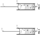
- FIG. 6 is a front view of a partially-constructed lens assembly having a fourth optical element, in accordance with an embodiment of the disclosure.
- FIG. 7A is a front view of a completed lens assembly including six optical elements, in accordance with an embodiment of the disclosure.
- FIG. 7B is a front view of a complete lens assembly having optional protective elements at each end of the assembly, in accordance with an embodiment of the disclosure.
- FIG. 8 depicts an operational flow relating to a method of fabricating a lens assembly, in accordance with an embodiment of the disclosure.
- Embodiments of an apparatus, system, and method for fabricating a lens assembly are described herein.
- numerous specific details are set forth to provide a thorough understanding of the embodiments.
- One skilled in the relevant art will recognize, however, that the techniques described herein can be practiced without one or more of the specific details, or with other methods, components, materials, etc.
- well-known structures, materials, or operations are not shown or described in detail to avoid obscuring certain aspects.
- the apparatus, system, and method for fabricating a lens assembly that are described in this disclosure include a tube into which a precise volume of curable optical polymer is conveyed.
- the volume of optical polymer is engaged by at least one plunger inserted into the tube, the plunger having a lensing curvature which causes the optical polymer adjacent to the plunger to take on a shape defined by the curvature.
- Radiant energy is applied to the tube and polymer from the outside of the tube.
- the radiated energy passes into the tube and cures the polymer, causing the polymer to form a rigid optical element.
- the plunger is then removed from the tube, leaving the rigid optical element with the aforementioned lensing curvature.
- One or more additional optical elements may be formed within the tube through successive operations of inserting polymer into the tube, engaging the polymer with a plunger having a desired lensing curvature, and curing the polymer.
- the resulting lens assembly is therefore constructed in a beneficial manner in which the optical elements within the tube may be aligned coaxially along the optical axes of the individual elements, with the tube then being able to be easily integrated as a single lens assembly component of a virtual reality system, head mounted display, or other mobile or wearable device.
- FIG. 1 is a perspective view of a head mounted display (HMD) 100 into which a lens assembly is integrated, in accordance with an embodiment of the disclosure.
- the illustrated example of HMD 100 is shown as including a viewing structure 140 , a top securing structure 141 , a side securing structure 142 , a rear securing structure 143 , and a front rigid body 144 .
- the HMD 100 is configured to be worn on a head of a user of the HMD 100 , where the top securing structure 141 , side securing structure 142 , and/or rear securing structure 143 may include a fabric strap including elastic as well as one or more rigid structures (e.g., plastic) for securing the HMD 100 to the head of the user.
- HMD 100 may also optionally include one or more earpieces 120 for delivering audio to the ear(s) of the user of the HMD 100 .
- the illustrated example of HMD 100 also includes an interface membrane 118 for contacting a face of the user of the HMD 100 , where the interface membrane 118 functions to block out at least some ambient light from reaching to the eyes of the user of the HMD 100 .
- Example HMD 100 may also include a chassis for supporting hardware of the viewing structure 140 of HMD 100 (chassis and hardware not explicitly illustrated in FIG. 1 ).
- the hardware of viewing structure 140 may include any of processing logic, wired and/or wireless data interface for sending and receiving data, graphic processors, and one or more memories for storing data and computer-executable instructions.
- viewing structure 140 may be configured to receive wired power and/or may be configured to be powered by one or more batteries.
- viewing structure 140 may be configured to receive wired and/or wireless data including video data.
- an eye-tracking camera may be included in viewing structure 140 to capture image(s) of an eye of a user of HMD 100 .
- Viewing structure 140 may also include a display system having one or more electronic displays for directing light to the eye(s) of a user of HMD 100 .
- the display system may include one or more of an LCD, an organic light emitting diode (OLED) display, or micro-LED display for emitting light (e.g., content, images, video, etc.) to a user of HMD 100 .
- HMD 100 may include an integrated lens assembly 150 oriented for operation in conjunction with an image sensor 152 in order to focus an image with particular image characteristics onto an image plane.
- the integrated lens assembly 150 includes at least one optical element having a refractive index that corresponds to the desired image characteristics.
- the integrated lens assembly bears two or more optical elements within a tube, the optical elements resting against one another and aligned coaxially along the optical axes of the individual elements.
- HMD is an example of a device that integrated lens assembly 150 may be included in. However, integrated lens assembly 150 may be incorporated into any device.
- FIGS. 2A and 2B are a front view and a top cross-sectional view of a tube 202 which provides the framework in which the optical elements are individually fabricated, transforming the tube 202 and fabricated optical elements into the lens assembly 150 discussed with respect to FIG. 1 .
- a cross-section of the tube 202 may be circular, or the cross-section may have an oval form or other profile (e.g. square, rectangular, etc.), according to the desired cross-sectional shape of the optical elements formed within the tube 202 and/or according to a cavity shape within a device such as HMD 100 that will receive the lens assembly.
- the tube 202 is optically transparent to at least some wavelengths of light.
- Those wavelengths could include one or more of ultraviolet (UV) light, infrared (IR) light, or light of a different wavelength.
- the tube 202 permits heat to pass through the sides of the tube 202 .
- the tube 202 may be constructed of glass, plastic, or another material having a desired transparency characteristic, and may be open-ended on one or both ends.
- a tube 202 may be segmented such that vertical segments of the tube 202 have differing shapes.
- a tube 202 may have a stepped shape in which the diameter of a first cylindrical tube cross-section may be different from a diameter of a second cylindrical tube cross-section. The foregoing stepped shape may aid in creation of optical elements formed within the tube 202 that have varying diameters.
- a tube 202 may have one or more tapering characteristics.
- a tube 202 may be wider at its top and narrower at its bottom, resulting from a narrowing taper from top to bottom of tube 202 .
- a taper may also aid in creation of optical elements formed within tube 202 having varying diameters.
- a stepped shape or taper of tube 202 may provide a particular shape for the finished lens assembly which suits the needs of the device in which the lens assembly will be placed.
- the tube 202 is held in place vertically by a fixture (not shown) and is plumb (e.g., the sides of the tube 202 are parallel to the force of gravity).
- a first plunger 206 may be inserted into the tube 202 from a bottom end of the tube 202 .
- the first plunger 206 includes a first plunger head 208 .
- the first plunger head 208 may include a cavity, the curvature of the cavity defining a desired lensing curvature 209 for the bottom surface of a first optical element fabricated in the assembly.
- the first plunger head 208 shown in the figures is concave with respect to the top of the tube, the first plunger head 208 may be concave, convex, or have another shape according to the particular curvature needs for the first optical element of the desired lens assembly.
- a curvature provided by a plunger head is constant across a surface such that the surface may be referred to as spherical.
- a concave or convex plunger head cavity may provide the aforementioned constant curvature.
- a curvature may be aspherical where the curvature varies over the surface, and a correspondingly shaped plunger head may be provided.
- the curvature provided by a plunger head may not necessarily be rotationally symmetric.
- the plunger head 208 may include a diffractive structure to form a diffractive optical element.
- the plunger head 208 is sized to closely fit an inside shape of the tube 202 (i.e. the plunger head 208 has a perimeter resting against the interior sidewall 220 of the tube 202 and has an outer boundary just smaller than the inner boundary of the tube 202 , etc.).
- a bottom face of the tube 202 may be closed such that a bottom surface of a first optical element fabricated in the assembly is flat.
- Interior sidewall 220 is disposed opposite of exterior sidewall 230 (i.e. exterior sidewall 230 is disposed along the outer wall of tube 202 ).
- a volume of curable optical polymer 314 is provided to the tube 202 .
- a source such as a syringe (not shown), is controlled to dispense a precise volume of the optical polymer, which falls or is otherwise conveyed into the tube.
- the polymer be composed of one or more drops (such as polymer drop 314 A, 314 B, and 314 C depicted in FIG. 3A )
- the polymer upon landing upon the first plunger head 208 the polymer drops coalesce to form a single volume.
- the close fit of the plunger head 208 to the inside shape of the tube 202 ensures that all optical polymer 314 conveyed into the tube 202 remains within the tube 202 (i.e. that no portion of optical polymer 314 runs past the plunger 206 and out through the bottom of the tube 202 ).
- a second plunger 310 is inserted into the top of tube 202 .
- the second plunger 310 includes a second plunger head 312 .
- the second plunger head 312 may include a cavity.
- the curvature of the cavity may define a desired lensing curvature 313 for the top surface of the first optical element fabricated in the assembly. While the cavity of the second plunger head 312 shown in the figures is concave with respect to the bottom of the tube, the second plunger head 312 may be concave or convex.
- the second plunger 310 is brought into contact with the volume of the curable optical polymer, causing the volume to conform to the curvature of the first and second plunger heads 208 and 312 and take on the desired shape for the optical element 320 .
- the second plunger head 312 is sized to closely fit an inside shape of the tube 202 , preventing any of the precisely-measured volume of optical polymer from passing between the plunger head 312 and the sides of the tube.
- a curing operation occurs while the second plunger 310 is in the tube 202 , which may involve radiant energy 318 being passed through the tube 202 , the radiant energy 318 emanating from an energy source 316 .
- the radiant energy 318 is light having a particular wavelength selected in order to propagate through the tube 202 to illuminate the volume of the curable optical polymer
- the energy source 316 is an emitter of the light having the particular wavelength.
- the energy source 316 may be an ultraviolet lamp or LED
- radiant energy 318 may be ultraviolet light, the ultraviolet lamp and light corresponding to optical polymer which is reactive particularly to ultraviolet light.
- the radiant energy 318 is thermal energy selected to propagate through the tube 202 and heat the volume of curable optical polymer.
- the radiant energy 318 may also propagate through the first plunger head 208 and/or the second plunger head 312 , either via light or heat.
- the curing operation may include ceasing or diminishing thermal energy as radiant energy 318 so that optical element 320 is allowed to cool and cure.
- the second plunger 310 is removed from the tube 202 after the curing operation.
- the optical polymer hardens in order to retain its molded shape upon the second plunger 310 being removed from the tube 202 .
- the cured optical polymer remains in the tube 202 , forming an optical element 320 including a top lensing curvature 313 defined by the head 312 of the second plunger 310 .
- the optical polymer may shrink.
- a plunger head size or shape is selected and/or adjusted to account for anticipated shrinkage of the volume of optical polymer in accordance with known shrink characteristics of the particular optical polymer in use.
- plunger head 208 and/or plunger head 310 imparts a diffractive structure into the optical polymer to form a diffractive optical element as optical element 320 .
- At least a part of the optical element 320 remains adhered to the interior sidewall of the tube 202 after removal of the second plunger 310 .
- an outer boundary or ring 315 of the optical element 320 in contact with the inside of tube 202 may bond with the inside of tube 202 at an interior sidewall of the tube (i.e. interior sidewall 220 as illustrated in FIG. 2B ) as a result of the curing operation.
- the bond of the ring 315 around the optical element 320 to the inside of the tube created during curing may cause the optical element to adhere to the tube 202 and remain in place following removal of the second plunger 310 .
- the ring 315 portion of optical element 320 bonding to the tube 202 during the curing operation may result, for example, from the precise metering of just enough optical polymer into tube 202 to cause the optical polymer to flow in a thin stream, upon insertion of the second plunger 310 , all the way to the interior sidewall of the tube 202 .
- FIGS. 4A-4D illustrate front views of the tube 202 having the first optical element 320 present.
- fabrication of a second optical element on top of the first optical element takes place.
- a volume of curable optical polymer 414 is provided to the tube 202 .
- the curable optical polymer 414 may be the same material discussed with respect to FIG. 3A (i.e. it may be the same material as the curable optical polymer 314 provided to the tube to fabricate the first optical element 320 ).
- the curable optical polymer 414 may have different optical characteristics, such as a different refractive index, different corresponding light wavelength or corresponding temperature for curing, or other difference.
- the polymer may be composed of one or more drops, such as polymer drop 414 A, 414 B, and 414 C depicted in FIG. 4B that coalesce upon landing to form a single volume.
- a subsequent plunger 410 is inserted into the top of the tube 202 .
- the subsequent plunger 410 includes plunger head 412 , which may include a surface defining a desired lensing curvature 413 for the top surface of the second optical element.
- the surface of the plunger head 412 may be concave or convex according to the particular needs for the top surface of the second optical element of the desired lens assembly. (The plunger head 412 is depicted in FIGS. 4B-4D as being concave with respect to the bottom of the tube).
- the subsequent plunger 410 is brought into contact with the volume of curable optical polymer 414 , causing the volume to conform to the curvature of the top surface of the first optical element 320 and to the curvature 413 of the subsequent plunger head 412 in order to take on the desired shape for the second optical element 420 .
- Another curing operation occurs while the subsequent plunger 410 is in the tube 202 , which may involve radiant energy 418 being passed through the tube 202 , the radiant energy 418 emanating from an energy source 416 .
- Radiant energy 418 may have the same or a different wavelength or other radiant property as needed to correspond to the curing requirements of the curable optical polymer 414 .
- the subsequent plunger head 412 may have the same curvature 413 as the head of the first or second plungers described with respect to FIGS. 3A-3D , or may have a different curvature 413 , whereby a difference in optical elements fabricated with the various plungers having the same curvature may be effected through the use of optical polymers having differing refractive indices, for example.
- the subsequent plunger 410 is removed from the tube 202 after the curing operation.
- the cured optical polymer remains in the tube, forming a second optical element 420 atop, and in contact with, the first optical element 320 , the second optical element 420 including a bottom lensing curvature which is the inverse of the top lensing curvature of the first optical element 320 and including a top lensing curvature 413 defined by the head 412 of the subsequent plunger 410 .
- the optical axes of the first optical element 320 and the second optical element 420 will be aligned as a result of fabrication operations occurring within a circular cross-sectioned tube that is held in place vertically by the fixture.
- the second optical element 420 remains adhered to the interior sidewall of the tube 202 after removal of the subsequent plunger 410 .
- the adherence of the second optical element 420 to the interior sidewall of the tube 202 may occur in substantially the same manner as for the adherence of the first optical element 320 to the interior sidewall of the tube 202 described above with respect to FIG. 3D .
- FIG. 5 the partially-constructed lens assembly is shown following another set of operations similar to those depicted in FIGS. 3A-3D and FIGS. 4A-4D . That is, a volume of optical polymer has been provided to the tube 202 , resting upon the top surface of optical element 420 ; a plunger 510 has been inserted into the tube 202 with plunger head 512 coming into contact with the volume of optical polymer; a curing operation has occurred; and the plunger 510 is removed from the tube 202 subsequent to the volume of optical polymer being cured, resulting in a third optical element 520 having been formed with a bottom lensing curvature defined by the top surface of optical element 420 and a top lensing curvature 513 defined by the cavity of plunger head 512 of the plunger 510 .
- the plunger head 512 is convex relative to the bottom of the tube 202 , but the plunger head 512 may in other embodiments be concave or convex as needed to provide
- FIG. 6 the partially-constructed lens assembly is shown following another set of operations similar to those depicted in FIGS. 3A-3D and FIGS. 4A-4D .
- a fourth optical element 620 is formed within tube 202 , the fourth optical element 620 including a bottom lensing curvature defined by the top surface of optical element 520 and a top lensing curvature 613 defined by the cavity of plunger head 612 of plunger 610 .
- FIG. 7A a completed lens assembly 150 is shown in which a fifth optical element 720 and a sixth optical element 722 have been fabricated.
- the first plunger is also depicted as having been removed from the tube 202 .
- the first optical element 320 may, upon having been fabricated as depicted in FIGS. 3A-3D , have adhered to the interior sidewall of tube 202 . Accordingly, upon curing of the first optical element 320 , removal of a bottom plunger which was in place during the curing operations may be achieved.
- the lens assembly 150 discussed herein features six optical elements in a stack within the tube, the disclosed technique may be applied to create lens assemblies having any number of optical elements.
- FIG. 7B a completed lens assembly 150 is shown in which an optional protective element 702 a has been applied to the assembly discussed with respect to FIG. 7A at its top and in which an optional protective element 702 b has been applied to the assembly at its bottom.
- the optional protective elements may be constructed of glass, plastic, or other transparent material and may be optically neutral or near-neutral so as to not adversely modify the desired optical characteristics yielded by the stack of optical elements within the tube 202 .
- other elements may be inserted into the tube 202 in between fabrication of optical elements. Such elements may include windows, apertures, preformed glass, or plastic elements.
- diffractive optical elements may be included in lens assembly 150 .
- the various optical elements in lens assembly 150 may not necessarily be rotationally symmetric or may not necessarily be in light with an optical axis shared by other optical elements in the lens assembly 150 .
- Completed lens assembly 150 may be fabricated directly over an image sensor. This may contribute to miniaturizing the space required for a lens assembly to be paired with an image sensor.
- a lens assembly such as lens assembly 150 may be fabricated over an image sensor where the lens assembly has a nominal focal length.
- focus measurements e.g. analyzing digital images captured by the image sensor while the lens assembly focuses light onto an imaging plane of the image sensor
- an adjustment optical power value may be determined to improve the focus of a camera that includes that specific image sensor paired with a particular lens assembly.
- the lens assembly may be adjusted according to the adjustment optical power value to improve the focus of the lens assembly.
- the lens assembly is adjusted by adjusting a top radius of curvature of an optical element, such as optical element 722 .
- the tube may be coated to prevent light from entering the completed lens assembly from the sides of the tube 202 .
- coating may include spraying or painting the tube 202 , such as with a black and/or absorbing layer.
- an operation of removing the tube 202 from the lens assembly stack may occur to decrease a diameter of the finished lens assembly.
- FIG. 8 depicts an operational flow 800 relating to a method of fabricating a lens assembly, in accordance with an embodiment of the disclosure.
- the integrated lens assembly 150 may be fabricated, prior to integration with HMD 100 , through the operations of providing a volume of curable optical polymer to a tube at 802 (discussed in more detail with respect to FIG. 3A , above); inserting a plunger into the tube, the plunger including a head that contacts the curable optical polymer and defines a lensing curvature, and the head being sized to closely fit an inside shape of the tube, at 804 (discussed in more detail with respect to FIGS.
- process 800 The order in which some or all of the process blocks appear in process 800 should not be deemed limiting. Rather, one of ordinary skill in the art having the benefit of the present disclosure will understand that some of the process blocks may be executed in a variety of orders not illustrated, or even in parallel.
- Embodiments of the invention may include or be implemented in conjunction with an artificial reality system.
- Artificial reality is a form of reality that has been adjusted in some manner before presentation to a user, which may include, e.g., a virtual reality (VR), an augmented reality (AR), a mixed reality (MR), a hybrid reality, or some combination and/or derivatives thereof.
- Artificial reality content may include completely generated content or generated content combined with captured (e.g., real-world) content.
- the artificial reality content may include video, audio, haptic feedback, or some combination thereof, and any of which may be presented in a single channel or in multiple channels (such as stereo video that produces a three-dimensional effect to the viewer).
- artificial reality may also be associated with applications, products, accessories, services, or some combination thereof, that are used to, e.g., create content in an artificial reality and/or are otherwise used in (e.g., perform activities in) an artificial reality.
- the artificial reality system that provides the artificial reality content may be implemented on various platforms, including a head mounted display (HMD) connected to a host computer system, a standalone HMD, a mobile device or computing system, or any other hardware platform capable of providing artificial reality content to one or more viewers.
- HMD head mounted display
Landscapes
- Engineering & Computer Science (AREA)
- Health & Medical Sciences (AREA)
- Mechanical Engineering (AREA)
- Manufacturing & Machinery (AREA)
- Ophthalmology & Optometry (AREA)
- Physics & Mathematics (AREA)
- Optics & Photonics (AREA)
- General Physics & Mathematics (AREA)
- Oral & Maxillofacial Surgery (AREA)
- Thermal Sciences (AREA)
- Toxicology (AREA)
- Electromagnetism (AREA)
- Lenses (AREA)
- Casting Or Compression Moulding Of Plastics Or The Like (AREA)
- Lens Barrels (AREA)
- Optical Couplings Of Light Guides (AREA)
Abstract
Description
Claims (20)
Priority Applications (6)
| Application Number | Priority Date | Filing Date | Title |
|---|---|---|---|
| US16/706,859 US11458699B2 (en) | 2019-12-09 | 2019-12-09 | Fabricating a lens assembly |
| PCT/US2020/058439 WO2021118708A1 (en) | 2019-12-09 | 2020-10-31 | Fabricating a lens assembly |
| CN202080084860.1A CN114885605A (en) | 2019-12-09 | 2020-10-31 | Manufacture of lens assemblies |
| JP2022521577A JP2023504989A (en) | 2019-12-09 | 2020-10-31 | Fabrication of lens assembly |
| EP20811916.4A EP4072838A1 (en) | 2019-12-09 | 2020-10-31 | Fabricating a lens assembly |
| KR1020227023008A KR20220123514A (en) | 2019-12-09 | 2020-10-31 | Lens assembly manufacturing |
Applications Claiming Priority (1)
| Application Number | Priority Date | Filing Date | Title |
|---|---|---|---|
| US16/706,859 US11458699B2 (en) | 2019-12-09 | 2019-12-09 | Fabricating a lens assembly |
Publications (2)
| Publication Number | Publication Date |
|---|---|
| US20210170703A1 US20210170703A1 (en) | 2021-06-10 |
| US11458699B2 true US11458699B2 (en) | 2022-10-04 |
Family
ID=73544395
Family Applications (1)
| Application Number | Title | Priority Date | Filing Date |
|---|---|---|---|
| US16/706,859 Active 2041-02-16 US11458699B2 (en) | 2019-12-09 | 2019-12-09 | Fabricating a lens assembly |
Country Status (6)
| Country | Link |
|---|---|
| US (1) | US11458699B2 (en) |
| EP (1) | EP4072838A1 (en) |
| JP (1) | JP2023504989A (en) |
| KR (1) | KR20220123514A (en) |
| CN (1) | CN114885605A (en) |
| WO (1) | WO2021118708A1 (en) |
Families Citing this family (3)
| Publication number | Priority date | Publication date | Assignee | Title |
|---|---|---|---|---|
| USD951961S1 (en) * | 2020-01-30 | 2022-05-17 | Magic Leap, Inc. | Head strap |
| US11691363B2 (en) * | 2020-03-20 | 2023-07-04 | Steris Instrument Management Services, Inc. | Method of forming and incorporating a polymeric lens within a lens housing |
| WO2025048710A1 (en) * | 2023-08-30 | 2025-03-06 | Focuslight Singapore Pte. Ltd. | Overmolded lenses |
Citations (8)
| Publication number | Priority date | Publication date | Assignee | Title |
|---|---|---|---|---|
| US4121896A (en) | 1976-03-24 | 1978-10-24 | Shepherd Thomas H | Apparatus for the production of contact lenses |
| US20050058773A1 (en) * | 2003-08-06 | 2005-03-17 | Seiko Epson Corporation | Method of manufacturing micro lens, micro lens, optical device, optical transmitting device, laser printer head, and laser printer |
| US20080055736A1 (en) | 2006-08-30 | 2008-03-06 | Sony Corporation | Optical element and production device for producing same |
| US20130300009A1 (en) | 2012-05-10 | 2013-11-14 | Vage Oganesian | Method Of Making Stamped Multi-Layer Polymer Lens |
| US20130314591A1 (en) | 2010-11-24 | 2013-11-28 | Nokia Corporation | Optically Refracting Surfaces |
| US20150158259A1 (en) * | 2012-02-07 | 2015-06-11 | Hoya Lens Manufacturing Philippines Inc. | Polarized plastic lens for spectacles and method for manufacturing polarized plastic lens for spectacles |
| US20190204527A1 (en) | 2017-12-28 | 2019-07-04 | Nidec Sankyo Corporation | Lens unit and manufacturing method of metal mold |
| US20210283871A1 (en) * | 2016-09-06 | 2021-09-16 | The Australian National University | Method for fabricating lenses |
Family Cites Families (6)
| Publication number | Priority date | Publication date | Assignee | Title |
|---|---|---|---|---|
| JPS5936244B2 (en) * | 1978-03-28 | 1984-09-03 | 旭光学工業株式会社 | Composite lens and its manufacturing method |
| JP2005305938A (en) * | 2004-04-23 | 2005-11-04 | Seiko Precision Inc | Compound lens manufacturing method |
| US20110038028A1 (en) * | 2008-04-23 | 2011-02-17 | Saman Dharmatilleke | Optical Imaging Lens systems and components |
| JP2011245638A (en) * | 2010-05-24 | 2011-12-08 | Fujifilm Corp | LENS MANUFACTURING METHOD, LENS, AND IMAGING DEVICE |
| US10416461B2 (en) * | 2016-10-27 | 2019-09-17 | Facebook Technologies, Llc | Pancake lens with large FOV |
| WO2019209234A1 (en) * | 2018-04-23 | 2019-10-31 | Khalip Oleg Yurevich | Method for producing an optical element and device for implementing thereof |
-
2019
- 2019-12-09 US US16/706,859 patent/US11458699B2/en active Active
-
2020
- 2020-10-31 KR KR1020227023008A patent/KR20220123514A/en not_active Ceased
- 2020-10-31 JP JP2022521577A patent/JP2023504989A/en active Pending
- 2020-10-31 EP EP20811916.4A patent/EP4072838A1/en not_active Withdrawn
- 2020-10-31 WO PCT/US2020/058439 patent/WO2021118708A1/en not_active Ceased
- 2020-10-31 CN CN202080084860.1A patent/CN114885605A/en active Pending
Patent Citations (8)
| Publication number | Priority date | Publication date | Assignee | Title |
|---|---|---|---|---|
| US4121896A (en) | 1976-03-24 | 1978-10-24 | Shepherd Thomas H | Apparatus for the production of contact lenses |
| US20050058773A1 (en) * | 2003-08-06 | 2005-03-17 | Seiko Epson Corporation | Method of manufacturing micro lens, micro lens, optical device, optical transmitting device, laser printer head, and laser printer |
| US20080055736A1 (en) | 2006-08-30 | 2008-03-06 | Sony Corporation | Optical element and production device for producing same |
| US20130314591A1 (en) | 2010-11-24 | 2013-11-28 | Nokia Corporation | Optically Refracting Surfaces |
| US20150158259A1 (en) * | 2012-02-07 | 2015-06-11 | Hoya Lens Manufacturing Philippines Inc. | Polarized plastic lens for spectacles and method for manufacturing polarized plastic lens for spectacles |
| US20130300009A1 (en) | 2012-05-10 | 2013-11-14 | Vage Oganesian | Method Of Making Stamped Multi-Layer Polymer Lens |
| US20210283871A1 (en) * | 2016-09-06 | 2021-09-16 | The Australian National University | Method for fabricating lenses |
| US20190204527A1 (en) | 2017-12-28 | 2019-07-04 | Nidec Sankyo Corporation | Lens unit and manufacturing method of metal mold |
Non-Patent Citations (2)
| Title |
|---|
| International Searching Authority, Patent Cooperation Treaty, European Application No. PCT/US2020, dated Feb. 3, 2021, 7 pages./058439. |
| International Searching Authority, Patent Cooperation Treaty, Written Opinion of the International Searching Authority, European Application No. PCT/US2020/058439, dated Feb. 3, 2021, 9 pages. |
Also Published As
| Publication number | Publication date |
|---|---|
| US20210170703A1 (en) | 2021-06-10 |
| EP4072838A1 (en) | 2022-10-19 |
| KR20220123514A (en) | 2022-09-07 |
| WO2021118708A1 (en) | 2021-06-17 |
| CN114885605A (en) | 2022-08-09 |
| JP2023504989A (en) | 2023-02-08 |
Similar Documents
| Publication | Publication Date | Title |
|---|---|---|
| CN112997106B (en) | Catadioptric and refractive optical structures for beam shaping | |
| US11740392B1 (en) | Optical lens assemblies and related methods | |
| US8384999B1 (en) | Optical modules | |
| CN217879825U (en) | optical system | |
| US9366869B2 (en) | Thin curved eyepiece for see-through head wearable display | |
| US11458699B2 (en) | Fabricating a lens assembly | |
| US9568734B1 (en) | Lens with lightguide insert for head wearable display | |
| US10007115B2 (en) | Placement of a computer generated display with focal plane at finite distance using optical devices and a see-through head-mounted display incorporating the same | |
| TWI477806B (en) | Optical camera lens, image capturing device and portable device | |
| US10359545B2 (en) | Fresnel lens with reduced draft facet visibility | |
| TWI617831B (en) | Optical imaging lens, image capturing apparatus and electronic device | |
| TWI545365B (en) | Image lens group, image capturing device and electronic device | |
| TWI616676B (en) | Imaging lens assembly, image capturing apparatus and electronic device | |
| US10880542B1 (en) | Near-eye optical element with embedded hot mirror | |
| CN113977998A (en) | Prescription lens manufacture | |
| US11054646B1 (en) | Head-mounted display device with Fresnel lenses | |
| US7916410B1 (en) | Lens, method for making same, and related lens module | |
| CN104749762A (en) | Optical magnifying combination mirror, head-mounted display optical system and equipment | |
| US20200400952A1 (en) | Lens with internal aperture | |
| US11061232B2 (en) | Method and apparatus for an imaging lens | |
| US11613090B1 (en) | Lens casting with deformable molds | |
| US11850811B1 (en) | Monolithic compound lens | |
| CN217112894U (en) | Lens Modules and Head Mounted Devices | |
| CN117891070A (en) | Head-up display and vehicle | |
| CN119148393B (en) | A large image plane and high resolution near-eye detection lens |
Legal Events
| Date | Code | Title | Description |
|---|---|---|---|
| FEPP | Fee payment procedure |
Free format text: ENTITY STATUS SET TO UNDISCOUNTED (ORIGINAL EVENT CODE: BIG.); ENTITY STATUS OF PATENT OWNER: LARGE ENTITY |
|
| AS | Assignment |
Owner name: FACEBOOK TECHNOLOGIES, LLC, CALIFORNIA Free format text: ASSIGNMENT OF ASSIGNORS INTEREST;ASSIGNORS:JENKINS, KURT ALLEN;LICHTENHAN, CHAD;SCHAUB, MICHAEL PATRICK;AND OTHERS;SIGNING DATES FROM 20191230 TO 20200113;REEL/FRAME:051567/0370 |
|
| STPP | Information on status: patent application and granting procedure in general |
Free format text: APPLICATION DISPATCHED FROM PREEXAM, NOT YET DOCKETED |
|
| STPP | Information on status: patent application and granting procedure in general |
Free format text: DOCKETED NEW CASE - READY FOR EXAMINATION |
|
| STPP | Information on status: patent application and granting procedure in general |
Free format text: NOTICE OF ALLOWANCE MAILED -- APPLICATION RECEIVED IN OFFICE OF PUBLICATIONS |
|
| AS | Assignment |
Owner name: META PLATFORMS TECHNOLOGIES, LLC, CALIFORNIA Free format text: CHANGE OF NAME;ASSIGNOR:FACEBOOK TECHNOLOGIES, LLC;REEL/FRAME:060246/0845 Effective date: 20220318 |
|
| STPP | Information on status: patent application and granting procedure in general |
Free format text: PUBLICATIONS -- ISSUE FEE PAYMENT VERIFIED |
|
| STCF | Information on status: patent grant |
Free format text: PATENTED CASE |
|
| MAFP | Maintenance fee payment |
Free format text: PAYMENT OF MAINTENANCE FEE, 4TH YEAR, LARGE ENTITY (ORIGINAL EVENT CODE: M1551); ENTITY STATUS OF PATENT OWNER: LARGE ENTITY Year of fee payment: 4 |