US11458607B2 - Press device - Google Patents
Press device Download PDFInfo
- Publication number
- US11458607B2 US11458607B2 US16/472,577 US201716472577A US11458607B2 US 11458607 B2 US11458607 B2 US 11458607B2 US 201716472577 A US201716472577 A US 201716472577A US 11458607 B2 US11458607 B2 US 11458607B2
- Authority
- US
- United States
- Prior art keywords
- contact surface
- press
- axis
- curvature
- press device
- Prior art date
- Legal status (The legal status is an assumption and is not a legal conclusion. Google has not performed a legal analysis and makes no representation as to the accuracy of the status listed.)
- Active, expires
Links
Images


Classifications
-
- B—PERFORMING OPERATIONS; TRANSPORTING
- B25—HAND TOOLS; PORTABLE POWER-DRIVEN TOOLS; MANIPULATORS
- B25B—TOOLS OR BENCH DEVICES NOT OTHERWISE PROVIDED FOR, FOR FASTENING, CONNECTING, DISENGAGING, OR HOLDING
- B25B27/00—Hand tools, specially adapted for fitting together or separating parts or objects whether or not involving some deformation, not otherwise provided for
- B25B27/02—Hand tools, specially adapted for fitting together or separating parts or objects whether or not involving some deformation, not otherwise provided for for connecting objects by press fit or detaching same
- B25B27/10—Hand tools, specially adapted for fitting together or separating parts or objects whether or not involving some deformation, not otherwise provided for for connecting objects by press fit or detaching same inserting fittings into hoses
-
- B—PERFORMING OPERATIONS; TRANSPORTING
- B21—MECHANICAL METAL-WORKING WITHOUT ESSENTIALLY REMOVING MATERIAL; PUNCHING METAL
- B21D—WORKING OR PROCESSING OF SHEET METAL OR METAL TUBES, RODS OR PROFILES WITHOUT ESSENTIALLY REMOVING MATERIAL; PUNCHING METAL
- B21D39/00—Application of procedures in order to connect objects or parts, e.g. coating with sheet metal otherwise than by plating; Tube expanders
- B21D39/04—Application of procedures in order to connect objects or parts, e.g. coating with sheet metal otherwise than by plating; Tube expanders of tubes with tubes; of tubes with rods
- B21D39/048—Application of procedures in order to connect objects or parts, e.g. coating with sheet metal otherwise than by plating; Tube expanders of tubes with tubes; of tubes with rods using presses for radially crimping tubular elements
-
- B—PERFORMING OPERATIONS; TRANSPORTING
- B21—MECHANICAL METAL-WORKING WITHOUT ESSENTIALLY REMOVING MATERIAL; PUNCHING METAL
- B21D—WORKING OR PROCESSING OF SHEET METAL OR METAL TUBES, RODS OR PROFILES WITHOUT ESSENTIALLY REMOVING MATERIAL; PUNCHING METAL
- B21D39/00—Application of procedures in order to connect objects or parts, e.g. coating with sheet metal otherwise than by plating; Tube expanders
- B21D39/04—Application of procedures in order to connect objects or parts, e.g. coating with sheet metal otherwise than by plating; Tube expanders of tubes with tubes; of tubes with rods
- B21D39/046—Connecting tubes to tube-like fittings
-
- H—ELECTRICITY
- H01—ELECTRIC ELEMENTS
- H01R—ELECTRICALLY-CONDUCTIVE CONNECTIONS; STRUCTURAL ASSOCIATIONS OF A PLURALITY OF MUTUALLY-INSULATED ELECTRICAL CONNECTING ELEMENTS; COUPLING DEVICES; CURRENT COLLECTORS
- H01R43/00—Apparatus or processes specially adapted for manufacturing, assembling, maintaining, or repairing of line connectors or current collectors or for joining electric conductors
- H01R43/04—Apparatus or processes specially adapted for manufacturing, assembling, maintaining, or repairing of line connectors or current collectors or for joining electric conductors for forming connections by deformation, e.g. crimping tool
- H01R43/042—Hand tools for crimping
- H01R43/0428—Power-driven hand crimping tools
Definitions
- the present invention relates to a press device for pressing or crimping tubular workpieces together.
- a press ring enables the crimping of tubular workpieces with an arbitrary diameter. Simply the diameter of the press ring has to be adjusted to the diameter of the workpiece. Then the press ring can be pressed together by means of a usually sized press tool.
- the press tool itself remains the same independent of the size of the tubular workpiece. As for many tools, also the press tool shall be usable a lot of times. Thus, damages and abrasions on the tools, i.e. the press ring and the press tool, shall be prevented.
- Document DE 20 2006 004 876 U1 describes a pressing tool with a pressing ring and pressing tongs that are associated with pairs of cooperating engagement surfaces, wherein one engagement surface of each pair is flat and the other curved.
- the curved engagement surface is concave, in particular substantially formed as part of an outer surface of a cylinder, a barrel or a ball.
- Document US 2003/230 130 A1 describes assemblies for articulating a crimp ring for crimping a fitting relative to an actuator for actuating the crimp ring.
- embodiments include for example articulating assemblies using ball and sockets.
- a press device comprising a press ring for pressing together tubular workpieces in between, and at least a first and a second pivotable jaw, wherein the first jaw comprises a first engagement section and the second jaw comprises a second engagement section, and the press ring comprises a first and a second receiving section for receiving the first and the second engagement section of the press jaws, respectively, wherein a first and a second surface of the first and the second receiving section, respectively, contacting the first and the second engagement section, respectively, each comprise a planar surface, and the first engagement section comprises a first contact surface and the second engagement section comprises a second contact surface, wherein the first and the second contact surface oppose each other for applying a press force, wherein the first contact surface and the second contact surface each comprise at least one convex surface, wherein a radius of curvature of the first and the second contact surface is larger than half a width, measured perpendicular to an axis of curvature, of the respective first and
- a press ring in combination with press jaws tubular workpieces like pipes or pipe connectors with a larger diameter, i.e. preferably up to 150 mm, more preferably up to 180 mm, and most preferably up to 250 mm in diameter, can be pressed together without the need that the press jaws themselves have to encompass the whole workpiece.
- the press ring is easily adaptable to different diameter sizes. Thus, with the same press jaws workpieces with extremely different diameter sizes can be pressed or crimped together.
- the first and the second press jaw of the press device are able to engage the press ring from two different opposing sides to impose a press force what enables the press or crimping process.
- the press ring is composed of at least two ring segments that are pivotable affixed to each other. In an open position of the press ring a workpiece that is to be pressed or crimped can be inserted into the press ring and by closing the press ring the press forces are applied onto the workpiece. As a result, the workpieces are mechanically connected.
- the first and the second receiving section of the press ring facilitate the engagement of the first and the second engagement section with the press ring.
- the surfaces of the first and the second receiving section preferably comprise a planar, preferably flat and smooth surface.
- a planar surface is more easy to manufacture than any curved or otherwise formed surface.
- a small rim around the first and the second receiving section ensures a secured engagement without the risk of slipping of the first or the second engagement section.
- a preferably circular shape of the first and the second receiving section enables an engagement of the press jaws from different angles with respect to the press ring. Thus, it is possible to work from different position while still engaging properly. So, working in small or complicated environments is facilitated.
- the shape of the first and the second contact surfaces are adapted to a desired force transmission pattern by at least one convex surface at each of the two contact surfaces.
- a convex shape of at least a part of the first and the second contact surface enables an even distribution of occurring press forces over a larger area than other contact surfaces designs for example a semi-spherical surface or a surface comprising sharp edges at its ends. In the former case, the forces would be focused and transmitted in only one contact point what would lead to a high stress of the material at that point.
- the convex surface comprise a rather flat curvature, so that there are no sharp edges while at the same time the contact area of the first and the second contact surface is as large as possible during the press process.
- the contact surfaces of the press jaws are prevented from damage due to unwanted cuts from sharp edges or too much stress in certain areas of the surface of the first and the second receiving section, respectively. This will prolong the lifetime of the press jaws.
- the first and the second contact surface are essentially rectangular in a projection into an x-z-plane and comprise a first convex surface curved around an axis parallel to the z-axis only at a proximal end of the first and the second contact surface, respectively.
- the press forces can be distributed equally over a large area during the press process, particular at the end of the press process where the highest forces occur, what prevents the contact surfaces from damage.
- the first and the second contact surface is essentially rectangular in a projection into an x-z-plane and comprise a first convex surface curved around an axis parallel to the z-axis at the proximal end and a second convex surface curved around an axis parallel to the z-axis at a distal end of the first and the second contact surface and a planar surface in between.
- sharp edges at the distal and at the proximal end of the first and the second engagement section are prevented while a relatively large flat contact area is remained where the applied forces during a press procedure can distribute equally.
- An equal distribution of forces over a large area reduces wear off and provides a long lifetime.
- the rounded first and second convex surface prevent the generation of cuts or grooves on the contact surfaces of the first and the second receiving section and ensure a uniform force transmission in the open position as well as in the closed position of the press jaws.
- the first and the second contact surface are essentially rectangular in a projection into an x-z-plane and comprise one overall convex surface curved around an axis parallel to the z-axis.
- This configuration like the one before does not comprise any edges at the first and second engagement section of the press jaws, thus, damages to the surface of the first and the second receiving section due to extremely focused forces at edges are prevented.
- the first and the second contact surface are further curved around an axis parallel to the x-axis at the right end of the contact surface and are curved around an axis parallel to the x-axis at the left end of the contact surface and are linear in between.
- a rounded first and second contact surface can be obtained that are rounded in the other main direction while there is a relatively large contact area at the center.
- the large contact area reduces the impact of the acting forces per surface area and prevents the surfaces from damage.
- the first and second contact surface rounded at their left and right side allow for engaging the first and second receiving section, respectively, at different angles while still avoiding any cuts or grooves on the surfaces of the first and the second receiving section.
- wear off is further reduced and the lifetime of the press jaws and thus the press device is increased.
- first and the second contact surface are further continuously linear in z-direction. This configuration enables the largest contact area during a press process. Due to the fact that the press forces are distributed over a large area stress in certain regions of the first and the second contact surface is reduced what prevents the press jaws from damage.
- first and the second contact surface are further overall curved around an axis parallel to the x-axis.
- the resulting barrel-like surface shape enables a rounded first and second contact surface in essentially every engagement direction while at the center there is still the largest contact area so that the occurring press forces can distribute over a large surface area.
- no sharp edges will damage the surface of the first and the second receiving section, respectively, regardless of the engagement angle with which the first and the second engagement section engages with the respective first and second receiving section.
- the radius of curvature of the first and the second contact surface is preferably larger than twice the width, measured perpendicular to the axis of curvature, more preferably larger than three times the width, and most preferably larger than five times the width, of the respective first and second contact surface.
- the curvature shall be as flat as possible in order to achieve a broad contact area where forces can be transmitted, particular in a vertical direction or in this case the y-direction, from the surfaces of the engagement sections to the surfaces of the receiving sections.
- the stress on each of the surface portions is reduced. Less stress of certain areas or parts of the press device may prolong its lifetime.
- the radius of curvature of the first and the second contact surface is constant. Using this shape a uniform force transmission at every engagement angle is possible.
- the first and the second contact surface comprise a smooth surface.
- a smooth surface without any non-continuous surface element avoids the generation of unwanted cuts or grooves on the contact surfaced during the press process. Furthermore, the forces are transmitted equally about the whole first and second contact surface, respectively.
- the press jaws further comprise a first and a second connecting member for connecting the first and the second press jaw wherein the first and the second press jaw are pivotally affixed to the first and the second connecting member.
- connection of two press jaws enables an opposite engagement of the press jaws on the press ring. Due to the fact that the first and the second press jaw are pivotally affixed to the first and the second connecting member leverage forces can be used what makes the press process more comfortable since high press forces can be achieved by applying only small forces on the other side of the lever arms, i.e. at the press tool, a handle or the like.
- first and the second connecting member are arranged at opposite sides of the first and the second press jaw.
- the arrangement of the first and the second connecting member on both sides of the press jaws serves to keep the press jaws in their predetermined working plane. This enables a symmetrical configuration of the press jaws.
- the arrangement of two opposite or parallel connecting members leads to a symmetric distribution of the occurring forces what reduces disproportionately high stress of the material in certain areas.
- first and the second connecting member comprise at least two holes for inserting bolts by which the first and the second press jaw are pivotally affixed to the first and second connecting member.
- bolts By using bolts as a connection between the press jaws and the connecting members large forces can be applied.
- the first and the second connecting member comprise a hole for connecting the press jaws to a press tool.
- a pivotable bolt-connection may be used for connecting the press tool header with a press tool. By such hole for a bolt-connection large forces may be transmitted that facilitate the press process.
- FIG. 1 is a side view in the x-y plane of a schematic illustration of an embodiment of a press device with press jaws in a closed position.
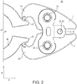
- FIG. 2 is a side view in the x-y plane of a schematic illustration of the press device of FIG. 1 in an open position.
- FIG. 3 is a side view in the x-y plane of a partially cut schematic illustration of the press device of FIG. 1 in a closed position to show the contact surfaces.
- FIG. 4 is a side view in the x-y plane of a partially cut schematic illustration of the press device of FIG. 3 in an open position.
- FIG. 5 is a three-dimensional perspective view of a schematic illustration of the press device of FIG. 1 in a closed position.
- FIG. 6 is a three-dimensional perspective view of a schematic illustration of the press device of FIG. 5 in an open position.
- FIG. 7 is a three-dimensional perspective view of a schematic illustration of the press device of FIG. 1 in a closed position while the press jaws engage the press ring at 90° angle.
- FIG. 8 is a three-dimensional perspective view of a schematic illustration of the press device of FIG. 7 in an open position.
- FIG. 9 is a cross-sectional perspective view of a schematic illustration of the press device of FIG. 7 in a closed position.
- FIG. 10 is a cross-sectional perspective view of a schematic illustration of the press device of FIG. 9 in an open position.
- FIG. 11 is a cross-sectional side view of a schematic illustration of the press devices of FIG. 10 in an open position.
- FIG. 12A is a schematic cross-sectional view of the first and second engagement sections of the press jaws with the respective first and second contact surfaces.
- FIG. 12B is a schematic cross-sectional view of the first and second engagement sections of the press jaws with the respective first and second contact surfaces.
- FIG. 12C is a schematic cross-sectional view of the first and second engagement sections of the press jaws with the respective first and second contact surfaces.
- FIG. 12D is a schematic cross-sectional view of the first and second engagement sections of the press jaws with the respective first and second contact surfaces.
- FIG. 12E is a schematic cross-sectional view of the first and second engagement sections of the press jaws with the respective first and second contact surfaces.
- FIG. 12F is a schematic cross-sectional view of the first and second engagement sections of the press jaws with the respective first and second contact surfaces.
- FIG. 13 is a schematic top planar view in the x-z-plane of the first and second contact surface.
- FIG. 14 is a side view in the x-y plane of a schematic illustration of an embodiment of a press device with press jaws and a press ring in an open position.
- FIG. 15 is a side view in the x-y plane of a partially cut schematic illustration of the press device of FIG. 14 in an open position to show the contact surfaces.
- FIG. 1 and FIG. 2 show the press jaws 1 , 2 and parts of the press ring 40 of the present invention in a closed ( FIG. 1 ) and an open ( FIG. 2 ) position.
- the press jaws 1 , 2 together with the press ring 40 form the press device 50 .
- the press device 50 can be an electric or hydraulic actuated press device 50 .
- the first 10 and the second engagement section 20 of the press jaws 1 , 2 are already engaging the first 41 and the second receiving section 42 at the press ring 40 .
- the first 11 and the second contact surface 21 are masked by a small rim 43 at the first 41 and the second receiving section 42 . This rim 43 , secures the engagement and prevents a slipping of the first 10 and the second engagement section 20 from the first 41 and the second receiving section 42 , respectively.
- the further elements of a press tool like an electric motor are not shown in the figures but can be connected to the press jaws 1 , 2 via a bolt-connection at the holes 34 , 35 of the first 31 and the second connecting member 32 .
- Both connecting members 31 , 32 are arranged one after another in this view, thus, the second connecting member 32 is masked by the first connecting member 31 but will be visible in further figures.
- the press jaws 1 , 2 are pivotable affixed to the first 31 and the second connecting member 32 via bolt-connections using the bolts 33 , 33 ′.
- leverage forces of the press jaws 1 , 2 with respect to the first 31 and the second connecting member 32 can be used to press the first 10 and the second engagement section 20 of the press jaws 1 , 2 together by a force F and thus close the press ring 40 .
- a circumferential force is applied onto the surface of the outer tubular workpiece (not shown) that is to be pressed or crimped.
- FIG. 3 and FIG. 4 the above-mentioned rim 43 at the first 41 and the second receiving section 42 of the press ring 40 is partially left out for visualization purposes only.
- FIG. 3 shows the press ring 40 and the press jaws 1 , 2 in a closed position.
- the first 11 and the second contact surface 21 are in contact with the respective planar first 44 and second 45 surface of the first 41 and second receiving section 42 and provide a large contact area.
- the press jaws 1 , 2 and the press ring 40 of the present invention are in an open position.
- FIG. 5 and FIG. 6 show perspective views of the press jaws 1 , 2 and the press ring 40 of the present invention where the second connecting member 32 is now at least partially visible. Furthermore, it can be seen from these figures that the first 41 and the second receiving section 42 comprise a flat and circular shape. Thus, it is possible to engage the first 41 and the second receiving section 42 from different side and different angles by the first 10 and the second engagement section 20 of the press jaws 1 , 2 .
- FIG. 7 and FIG. 8 an engagement of the first 10 and the second engagement section 20 by an angle of about 90 degree with respect to the scenario of FIGS. 5 and 6 is shown. Due to the above-mentioned circular shape of the first 41 and the second receiving section 42 an engagement from different angles is possible.
- FIGS. 9 to 11 again the rim 43 at the first 41 and the second receiving section 42 is partially left out for visualization purposes only. Especially from FIG. 11 it can be seen that a three-dimensional curved first 11 and second contact surface 21 enables an edge-free engagement of the first 10 and the second engagement section 20 without damaging the planar first 44 and second 45 surface of the respective first 41 and second receiving section 42 .
- FIG. 12 different cross-sectional views of embodiments of the first 10 and the second engagement section 20 of the press jaws 1 , 2 of the present invention are displayed.
- FIGS. 12 a to 12 c show cross-sections in x-direction of the first 10 and the second engagement section 20 of the press jaws 1 , 2 .
- the illustrated cross-sectional views show the width Wx of the engagement sections 10 , 20 .
- the left side of each cross-section refers to the distal end 14 of the first 10 and the second engagement section 20 of the press jaws 1 , 2 , i.e. these distal ends 14 are further away from the center of the press jaws 1 , 2 than the proximal ends 13 .
- the right sides refer to the proximal end 13 of the first 10 and the second engagement section 20 , i.e. these sides are nearer to the center of the press jaws 1 , 2 than the distal ends 14 .
- the axis of curvature 60 extends in z-direction. The flatter the contact surface 11 , 21 , the larger the radius of curvature r and the further away the center of curvature or the axis of curvature 60 resp. lies from the contact surface 11 , 21 . The same holds for FIGS. 12D to 12F with the only difference that the engagement sections 10 , 20 are displayed in the y-z plane. Thus, there the axis of curvature 60 extends in x-direction.
- the first 11 and the second contact surface 21 at the proximal end 13 comprise a first convex surface 11 a , 21 a , in order to avoid any damages to the contact surfaces 11 and 21 when closing the press jaws 1 , 2 .
- the first convex surface 11 a , 21 a is in contact with the planar first 44 and second 45 surface of the respective first 41 and second receiving section 42 and adopts different angles when moving the press jaws 1 , 2 from the open to the closed position.
- FIG. 12 b shows a first 11 and a second contact surface 21 with a planar surface 11 b , 21 b at the center of the surface.
- FIGS. 12 d to 12 f show cross-sectional views of the first 10 and second engagement section 20 of the press jaws 1 , 2 in an y-z-plane, i.e. perpendicular to the x-direction.
- the left sides of the illustrated first 10 and second engagement section 20 refer to the left end 15
- the right sides of the illustrated first 10 and second engagement section 20 refer to the right end 16 of the first 10 and second engagement section 20 .
- the first 11 and the second contact surface 21 are further continuously linear 11 d , 21 d in z-direction.
- the linear extension 11 d , 21 d enables a large area of contact. Simultaneously it does not impair the operation because the edges at the right 16 and left end 15 of the first 10 and second engagement section 20 do not impact directly on the planar first 44 and second 45 surface of the respective first 41 and second receiving section 42 neither in the open nor in the closed position.
- FIG. 12 f having an overall curved section.
- the difference between the embodiments of FIG. 12 e and FIG. 12 f is the size of the area of contact. This contact area is larger in the embodiment of FIG. 12 e than in the embodiment of FIG. 12 f.
- FIG. 13 shows a top planar schematic illustration of the first 11 and the second contact surface 21 in an x-z-plane in order to designate the various edges of the contact surfaces 11 , 21 .
- the illustrated schematic projection of the at least partially curved first 11 and second contact surface 21 is rectangular with rounded corners.
- the proximal end is denoted with reference sign 13 and represents the end of the first 10 and second engagement section 20 or first 11 and second contact surface 21 , respectively, that are nearest to the center of the press jaws 1 , 2 .
- the opposite distal end is denoted by reference sign 14 and represents the end furthest away from the center of the press jaws 1 , 2 .
- the left end is denoted by reference sign 15 and the right end is denoted by reference sign 16 .
- FIG. 14 and FIG. 15 show the complete press device 50 of the present invention comprising the press jaws 1 , 2 and the press ring 40 .
- the press ring is almost closed, so as if it is arranged around a workpiece (not shown) that is to be pressed or crimped at the inner side/area of the press ring 40 .
- the press ring 40 is composed of at least two ring segments such that it can be largely opened to insert the workpiece in between the ring segments. After inserting the workpiece, the press ring 40 is arranged around large areas of the circumference of the workpiece and only a small portion at the right side of the press ring 40 in FIGS. 14 and 15 is left open.
- the resulting gap is then closed by using the press jaws and applying a force F to close the press ring 40 and thus mechanically combine/connect the workpiece with another workpiece (also not shown).
- a force F to close the press ring 40 and thus mechanically combine/connect the workpiece with another workpiece (also not shown).
- the present subject matter includes all operable combinations of features and aspects described herein. Thus, for example if one feature is described in association with an embodiment and another feature is described in association with another embodiment, it will be understood that the present subject matter includes embodiments having a combination of these features.
Landscapes
- Engineering & Computer Science (AREA)
- Mechanical Engineering (AREA)
- Press Drives And Press Lines (AREA)
- Manipulator (AREA)
Abstract
Description
- 1 first pivotable press jaw
- 2 second pivotable press jaw
- 10 first engagement section
- 11 first contact surface
- 11 a, 11 c first convex surface (first contact surface)
- 11 e, 11 g second convex surface (first contact surface)
- 11 f, 11 h overall convex surface (first contact surface)
- 11 b, 11 d planar surface (first contact surface)
- 13 proximal end
- 14 distal end
- 15 left end
- 16 right end
- 20 second engagement section
- 21 second contact surface
- 21 a, 21 c first convex surface (second contact surface)
- 21 e, 21 g second convex surface (second contact surface)
- 21 f, 21 h overall convex surface (second contact surface)
- 21 b, 21 d planar surface (second contact surface)
- 31 first connecting member
- 32 second connecting member
- 33, 33′ bolt
- 34 hole in first connecting member
- 35 hole in second connecting member
- 40 press ring
- 41 first receiving section
- 42 second receiving section
- 43 rim
- 44 first surface (first receiving section)
- 45 second surface (second receiving section)
- 50 press device
- 60 axis of curvature
- r radius of curvature
- F Press force x, y, z cartesian dimensions
- Wx width in x-dimension
- Wz width in (originally) z-dimension
Claims (15)
Applications Claiming Priority (4)
| Application Number | Priority Date | Filing Date | Title |
|---|---|---|---|
| EP16205748.3 | 2016-12-21 | ||
| EP16205748.3A EP3338954B1 (en) | 2016-12-21 | 2016-12-21 | Press device |
| EP16205748 | 2016-12-21 | ||
| PCT/EP2017/083520 WO2018114935A1 (en) | 2016-12-21 | 2017-12-19 | Press device |
Related Parent Applications (1)
| Application Number | Title | Priority Date | Filing Date |
|---|---|---|---|
| PCT/EP2017/083520 A-371-Of-International WO2018114935A1 (en) | 2016-12-21 | 2017-12-19 | Press device |
Related Child Applications (1)
| Application Number | Title | Priority Date | Filing Date |
|---|---|---|---|
| US17/892,181 Continuation US11612991B2 (en) | 2016-12-21 | 2022-08-22 | Press device |
Publications (2)
| Publication Number | Publication Date |
|---|---|
| US20200094388A1 US20200094388A1 (en) | 2020-03-26 |
| US11458607B2 true US11458607B2 (en) | 2022-10-04 |
Family
ID=57681354
Family Applications (2)
| Application Number | Title | Priority Date | Filing Date |
|---|---|---|---|
| US16/472,577 Active 2038-12-11 US11458607B2 (en) | 2016-12-21 | 2017-12-19 | Press device |
| US17/892,181 Active US11612991B2 (en) | 2016-12-21 | 2022-08-22 | Press device |
Family Applications After (1)
| Application Number | Title | Priority Date | Filing Date |
|---|---|---|---|
| US17/892,181 Active US11612991B2 (en) | 2016-12-21 | 2022-08-22 | Press device |
Country Status (4)
| Country | Link |
|---|---|
| US (2) | US11458607B2 (en) |
| EP (1) | EP3338954B1 (en) |
| CN (1) | CN110114189B (en) |
| WO (1) | WO2018114935A1 (en) |
Cited By (1)
| Publication number | Priority date | Publication date | Assignee | Title |
|---|---|---|---|---|
| DE102023100782B3 (en) | 2023-01-13 | 2024-05-02 | Novopress Gmbh Pressen Und Presswerkzeuge & Co. Kommanditgesellschaft | Press tool |
Families Citing this family (3)
| Publication number | Priority date | Publication date | Assignee | Title |
|---|---|---|---|---|
| CN111702088B (en) * | 2020-06-17 | 2024-12-31 | 艾默生精密工具技术(上海)有限公司 | Crimping tools |
| DE102021105243B4 (en) | 2021-03-04 | 2022-10-13 | Novopress Gmbh Pressen Und Presswerkzeuge & Co. Kg | pressing tool |
| DE202021102613U1 (en) | 2021-05-12 | 2022-08-18 | Novopress Gmbh Pressen Und Presswerkzeuge & Co. Kommanditgesellschaft | Press ring, press tool and adapter elements |
Citations (24)
| Publication number | Priority date | Publication date | Assignee | Title |
|---|---|---|---|---|
| US3345856A (en) * | 1964-12-23 | 1967-10-10 | Amp Inc | Tool for crimping electrical connectors |
| US5931067A (en) * | 1997-07-25 | 1999-08-03 | Gold; Lorne | Self adjusting pliers |
| US6044686A (en) | 1990-04-12 | 2000-04-04 | Dischler; Helmut | Compression tool for compression molding die |
| US6164106A (en) * | 1996-02-09 | 2000-12-26 | Novopress Gmbh Pressen Und Presserkzeuge & Co. Kg | Press apparatus |
| US6369560B1 (en) * | 1999-08-17 | 2002-04-09 | Novopress Gmbh Pressen Und Presswerkzeuge & Co., Kg | Handleable working device, in particular pressing device |
| US20030046973A1 (en) * | 2001-09-11 | 2003-03-13 | Hamm James E. | Crimping assembly |
| US6634202B1 (en) * | 1998-10-02 | 2003-10-21 | Hans Oetiker Ag Maschinen-Und Apparatefabrik | Device for arranging, clamping or contracting a ring shaped securing mechanism |
| US20030230130A1 (en) | 2002-06-17 | 2003-12-18 | Emerson Electric Co. | Assembly for articulating crimp ring and actuator |
| US6694586B1 (en) * | 1999-10-26 | 2004-02-24 | Emerson Electric Co. | Press tool for connecting workpieces by cold forming |
| US20050241359A1 (en) * | 2004-04-30 | 2005-11-03 | Viega Gmbh & Co., Kg | Pressing tool for the pressing-together of workpieces |
| DE202005008125U1 (en) | 2005-05-24 | 2006-10-05 | Herrle, Richard | Pressing tool, press ring and pressing tongs |
| DE202006004876U1 (en) | 2006-03-28 | 2007-08-02 | Herrle, Richard | Pressing tool, press ring and pressing tongs |
| US20080022750A1 (en) * | 2006-07-25 | 2008-01-31 | Emerson Electric Co. | Dual operation crimp and press jawset |
| US20080163664A1 (en) * | 2007-01-08 | 2008-07-10 | Wezag Gmbh Werkzeugfabrik | Pliers for Pressing Work Pieces |
| US20080216543A1 (en) * | 2004-11-24 | 2008-09-11 | Hamm James E | Enhanced Press Apparatus |
| US20090031778A1 (en) * | 2007-08-01 | 2009-02-05 | Emerson Electric Co. | Multi-application crimping or pressing tool |
| US7578159B2 (en) * | 2004-09-09 | 2009-08-25 | Emerson Electric Co. | Controlled cycle-life jaw assembly |
| EP1972394B1 (en) | 2007-03-22 | 2010-04-07 | Rothenberger AG | Pressing device for tubular workpieces |
| US7878790B2 (en) * | 2005-09-23 | 2011-02-01 | Bruns Daniel Kidd | Tool to crimp non-metallic tubing onto fittings |
| CN103003004A (en) | 2010-07-29 | 2013-03-27 | 金光赞 | Pipe press-connecting apparatus |
| CN104039247A (en) | 2011-09-14 | 2014-09-10 | 泰利福医疗公司 | Narrow profile surgical ligation clip |
| US20170225218A1 (en) * | 2014-06-09 | 2017-08-10 | Seowon Technology Co., Ltd. | Compression connection device for pipe |
| US11060637B2 (en) * | 2016-12-01 | 2021-07-13 | Ckd Corporation | Coupling member, fluid-device connecting jig, and fluid-device connecting structure |
| US11185907B2 (en) * | 2016-12-21 | 2021-11-30 | Von Arx Ag | Press ring with elongated holes |
Family Cites Families (1)
| Publication number | Priority date | Publication date | Assignee | Title |
|---|---|---|---|---|
| DE29721759U1 (en) * | 1997-12-10 | 1998-04-09 | Franz Viegener II GmbH & Co. KG, 57439 Attendorn | Press tool for the permanent connection of a fitting and an inserted metal pipe end |
-
2016
- 2016-12-21 EP EP16205748.3A patent/EP3338954B1/en active Active
-
2017
- 2017-12-19 CN CN201780079688.9A patent/CN110114189B/en active Active
- 2017-12-19 US US16/472,577 patent/US11458607B2/en active Active
- 2017-12-19 WO PCT/EP2017/083520 patent/WO2018114935A1/en not_active Ceased
-
2022
- 2022-08-22 US US17/892,181 patent/US11612991B2/en active Active
Patent Citations (25)
| Publication number | Priority date | Publication date | Assignee | Title |
|---|---|---|---|---|
| US3345856A (en) * | 1964-12-23 | 1967-10-10 | Amp Inc | Tool for crimping electrical connectors |
| US6044686A (en) | 1990-04-12 | 2000-04-04 | Dischler; Helmut | Compression tool for compression molding die |
| US6164106A (en) * | 1996-02-09 | 2000-12-26 | Novopress Gmbh Pressen Und Presserkzeuge & Co. Kg | Press apparatus |
| US5931067A (en) * | 1997-07-25 | 1999-08-03 | Gold; Lorne | Self adjusting pliers |
| US6634202B1 (en) * | 1998-10-02 | 2003-10-21 | Hans Oetiker Ag Maschinen-Und Apparatefabrik | Device for arranging, clamping or contracting a ring shaped securing mechanism |
| US6369560B1 (en) * | 1999-08-17 | 2002-04-09 | Novopress Gmbh Pressen Und Presswerkzeuge & Co., Kg | Handleable working device, in particular pressing device |
| US6694586B1 (en) * | 1999-10-26 | 2004-02-24 | Emerson Electric Co. | Press tool for connecting workpieces by cold forming |
| US20030046973A1 (en) * | 2001-09-11 | 2003-03-13 | Hamm James E. | Crimping assembly |
| US20030230130A1 (en) | 2002-06-17 | 2003-12-18 | Emerson Electric Co. | Assembly for articulating crimp ring and actuator |
| US6923037B2 (en) * | 2002-06-17 | 2005-08-02 | Emerson Electric Co. | Assembly for articulating crimp ring and actuator |
| US20050241359A1 (en) * | 2004-04-30 | 2005-11-03 | Viega Gmbh & Co., Kg | Pressing tool for the pressing-together of workpieces |
| US7578159B2 (en) * | 2004-09-09 | 2009-08-25 | Emerson Electric Co. | Controlled cycle-life jaw assembly |
| US20080216543A1 (en) * | 2004-11-24 | 2008-09-11 | Hamm James E | Enhanced Press Apparatus |
| DE202005008125U1 (en) | 2005-05-24 | 2006-10-05 | Herrle, Richard | Pressing tool, press ring and pressing tongs |
| US7878790B2 (en) * | 2005-09-23 | 2011-02-01 | Bruns Daniel Kidd | Tool to crimp non-metallic tubing onto fittings |
| DE202006004876U1 (en) | 2006-03-28 | 2007-08-02 | Herrle, Richard | Pressing tool, press ring and pressing tongs |
| US20080022750A1 (en) * | 2006-07-25 | 2008-01-31 | Emerson Electric Co. | Dual operation crimp and press jawset |
| US20080163664A1 (en) * | 2007-01-08 | 2008-07-10 | Wezag Gmbh Werkzeugfabrik | Pliers for Pressing Work Pieces |
| EP1972394B1 (en) | 2007-03-22 | 2010-04-07 | Rothenberger AG | Pressing device for tubular workpieces |
| US20090031778A1 (en) * | 2007-08-01 | 2009-02-05 | Emerson Electric Co. | Multi-application crimping or pressing tool |
| CN103003004A (en) | 2010-07-29 | 2013-03-27 | 金光赞 | Pipe press-connecting apparatus |
| CN104039247A (en) | 2011-09-14 | 2014-09-10 | 泰利福医疗公司 | Narrow profile surgical ligation clip |
| US20170225218A1 (en) * | 2014-06-09 | 2017-08-10 | Seowon Technology Co., Ltd. | Compression connection device for pipe |
| US11060637B2 (en) * | 2016-12-01 | 2021-07-13 | Ckd Corporation | Coupling member, fluid-device connecting jig, and fluid-device connecting structure |
| US11185907B2 (en) * | 2016-12-21 | 2021-11-30 | Von Arx Ag | Press ring with elongated holes |
Non-Patent Citations (2)
| Title |
|---|
| Chinese Office Action dated Jun. 29, 2020; Application No. CN 201780079688.9; 6 pages. |
| Extended European Search Report dated Jul. 13, 2017; App. EP 16205748.3; 9 pages. |
Cited By (1)
| Publication number | Priority date | Publication date | Assignee | Title |
|---|---|---|---|---|
| DE102023100782B3 (en) | 2023-01-13 | 2024-05-02 | Novopress Gmbh Pressen Und Presswerkzeuge & Co. Kommanditgesellschaft | Press tool |
Also Published As
| Publication number | Publication date |
|---|---|
| US20200094388A1 (en) | 2020-03-26 |
| CN110114189A (en) | 2019-08-09 |
| CN110114189B (en) | 2021-07-23 |
| US20230015222A1 (en) | 2023-01-19 |
| EP3338954B1 (en) | 2019-08-21 |
| EP3338954A1 (en) | 2018-06-27 |
| US11612991B2 (en) | 2023-03-28 |
| WO2018114935A1 (en) | 2018-06-28 |
Similar Documents
| Publication | Publication Date | Title |
|---|---|---|
| US11612991B2 (en) | Press device | |
| US6155095A (en) | Pliers including a pliers head and a positioning device | |
| WO2017178997A1 (en) | Power transfer pliers | |
| JP6224650B2 (en) | Crimping tool and crimping die | |
| JP2021504881A (en) | Crimping pliers | |
| US7997116B2 (en) | Link for crimping tool | |
| US8584503B1 (en) | Crimping tool | |
| US9481074B2 (en) | Locking plier jaws | |
| CN110858695B (en) | crimp pliers | |
| WO2014062201A3 (en) | Integral inspection gauge for manual crimping tool | |
| US7409847B2 (en) | Method and apparatus for securing connecting ferrules | |
| US20120279276A1 (en) | Tool with different effective areas | |
| JP2021091086A (en) | Hand plier tool and method for assembly thereof | |
| EP4678307A3 (en) | Apparatus and method for bending bars | |
| US20080022749A1 (en) | Electrical connector crimp die with crimp overlap indicia forming | |
| US20070199364A1 (en) | Crimping die and crimping tool | |
| TW201807911A (en) | Crimping hand tool | |
| EP2128512A3 (en) | Clamp installation tool | |
| US9327391B2 (en) | Crimping tool | |
| CN101450471A (en) | Pipe wrench | |
| CN110099759A (en) | Pressure ring with elongated hole | |
| KR20120093505A (en) | Compressor for press-connecting pipes | |
| US20110278781A1 (en) | Clamping device with coaxially rotating gripper pair | |
| CN215789239U (en) | Hand-operated pliers with adjustable moment | |
| US20100116118A1 (en) | Multi-Plane Hole Punch |
Legal Events
| Date | Code | Title | Description |
|---|---|---|---|
| FEPP | Fee payment procedure |
Free format text: ENTITY STATUS SET TO UNDISCOUNTED (ORIGINAL EVENT CODE: BIG.); ENTITY STATUS OF PATENT OWNER: LARGE ENTITY |
|
| AS | Assignment |
Owner name: VON ARX AG, SWITZERLAND Free format text: ASSIGNMENT OF ASSIGNORS INTEREST;ASSIGNORS:SCHWEIZER, BEAT;STUCKI, ANDREAS;HEER, MARIANNE;REEL/FRAME:049660/0663 Effective date: 20190621 |
|
| STCB | Information on status: application discontinuation |
Free format text: ABANDONED -- INCOMPLETE APPLICATION (PRE-EXAMINATION) |
|
| STPP | Information on status: patent application and granting procedure in general |
Free format text: DOCKETED NEW CASE - READY FOR EXAMINATION |
|
| AS | Assignment |
Owner name: EMERSON PROFESSIONAL TOOLS AG, SWITZERLAND Free format text: CHANGE OF NAME;ASSIGNOR:VON ARX AG;REEL/FRAME:056943/0300 Effective date: 20191112 |
|
| STPP | Information on status: patent application and granting procedure in general |
Free format text: NON FINAL ACTION MAILED |
|
| STPP | Information on status: patent application and granting procedure in general |
Free format text: RESPONSE TO NON-FINAL OFFICE ACTION ENTERED AND FORWARDED TO EXAMINER |
|
| STPP | Information on status: patent application and granting procedure in general |
Free format text: FINAL REJECTION MAILED |
|
| STPP | Information on status: patent application and granting procedure in general |
Free format text: NON FINAL ACTION MAILED |
|
| STPP | Information on status: patent application and granting procedure in general |
Free format text: RESPONSE TO NON-FINAL OFFICE ACTION ENTERED AND FORWARDED TO EXAMINER |
|
| STPP | Information on status: patent application and granting procedure in general |
Free format text: NOTICE OF ALLOWANCE MAILED -- APPLICATION RECEIVED IN OFFICE OF PUBLICATIONS |
|
| STPP | Information on status: patent application and granting procedure in general |
Free format text: PUBLICATIONS -- ISSUE FEE PAYMENT VERIFIED |
|
| STCF | Information on status: patent grant |
Free format text: PATENTED CASE |