US11454377B2 - Luminaire body, face ring and lighting device - Google Patents
Luminaire body, face ring and lighting device Download PDFInfo
- Publication number
- US11454377B2 US11454377B2 US17/374,951 US202117374951A US11454377B2 US 11454377 B2 US11454377 B2 US 11454377B2 US 202117374951 A US202117374951 A US 202117374951A US 11454377 B2 US11454377 B2 US 11454377B2
- Authority
- US
- United States
- Prior art keywords
- face
- lamp
- ring
- luminaire body
- mounting
- Prior art date
- Legal status (The legal status is an assumption and is not a legal conclusion. Google has not performed a legal analysis and makes no representation as to the accuracy of the status listed.)
- Active
Links
- 230000007246 mechanism Effects 0.000 claims abstract description 55
- 230000013011 mating Effects 0.000 claims description 16
- 239000013013 elastic material Substances 0.000 claims description 11
- 238000001746 injection moulding Methods 0.000 claims description 4
- 239000000463 material Substances 0.000 description 13
- 238000010586 diagram Methods 0.000 description 10
- 238000013016 damping Methods 0.000 description 9
- 230000009471 action Effects 0.000 description 6
- 239000002184 metal Substances 0.000 description 5
- 238000000034 method Methods 0.000 description 4
- 239000004033 plastic Substances 0.000 description 4
- 229920003023 plastic Polymers 0.000 description 4
- 230000008569 process Effects 0.000 description 3
- 230000003796 beauty Effects 0.000 description 2
- 230000000694 effects Effects 0.000 description 2
- 230000005489 elastic deformation Effects 0.000 description 2
- 238000005286 illumination Methods 0.000 description 2
- 230000001678 irradiating effect Effects 0.000 description 2
- 238000004519 manufacturing process Methods 0.000 description 2
- 230000004048 modification Effects 0.000 description 2
- 238000012986 modification Methods 0.000 description 2
- 239000000243 solution Substances 0.000 description 2
- 238000003491 array Methods 0.000 description 1
- 230000009286 beneficial effect Effects 0.000 description 1
- 230000008859 change Effects 0.000 description 1
- 230000006870 function Effects 0.000 description 1
- 230000001939 inductive effect Effects 0.000 description 1
- 238000009434 installation Methods 0.000 description 1
- 239000007769 metal material Substances 0.000 description 1
- 230000000087 stabilizing effect Effects 0.000 description 1
- 238000006467 substitution reaction Methods 0.000 description 1
- 238000004381 surface treatment Methods 0.000 description 1
- 230000007704 transition Effects 0.000 description 1
Images


Classifications
-
- F—MECHANICAL ENGINEERING; LIGHTING; HEATING; WEAPONS; BLASTING
- F21—LIGHTING
- F21S—NON-PORTABLE LIGHTING DEVICES; SYSTEMS THEREOF; VEHICLE LIGHTING DEVICES SPECIALLY ADAPTED FOR VEHICLE EXTERIORS
- F21S8/00—Lighting devices intended for fixed installation
- F21S8/02—Lighting devices intended for fixed installation of recess-mounted type, e.g. downlighters
- F21S8/026—Lighting devices intended for fixed installation of recess-mounted type, e.g. downlighters intended to be recessed in a ceiling or like overhead structure, e.g. suspended ceiling
-
- F—MECHANICAL ENGINEERING; LIGHTING; HEATING; WEAPONS; BLASTING
- F21—LIGHTING
- F21V—FUNCTIONAL FEATURES OR DETAILS OF LIGHTING DEVICES OR SYSTEMS THEREOF; STRUCTURAL COMBINATIONS OF LIGHTING DEVICES WITH OTHER ARTICLES, NOT OTHERWISE PROVIDED FOR
- F21V17/00—Fastening of component parts of lighting devices, e.g. shades, globes, refractors, reflectors, filters, screens, grids or protective cages
- F21V17/02—Fastening of component parts of lighting devices, e.g. shades, globes, refractors, reflectors, filters, screens, grids or protective cages with provision for adjustment
-
- F—MECHANICAL ENGINEERING; LIGHTING; HEATING; WEAPONS; BLASTING
- F21—LIGHTING
- F21V—FUNCTIONAL FEATURES OR DETAILS OF LIGHTING DEVICES OR SYSTEMS THEREOF; STRUCTURAL COMBINATIONS OF LIGHTING DEVICES WITH OTHER ARTICLES, NOT OTHERWISE PROVIDED FOR
- F21V17/00—Fastening of component parts of lighting devices, e.g. shades, globes, refractors, reflectors, filters, screens, grids or protective cages
- F21V17/10—Fastening of component parts of lighting devices, e.g. shades, globes, refractors, reflectors, filters, screens, grids or protective cages characterised by specific fastening means or way of fastening
- F21V17/16—Fastening of component parts of lighting devices, e.g. shades, globes, refractors, reflectors, filters, screens, grids or protective cages characterised by specific fastening means or way of fastening by deformation of parts; Snap action mounting
-
- F—MECHANICAL ENGINEERING; LIGHTING; HEATING; WEAPONS; BLASTING
- F21—LIGHTING
- F21V—FUNCTIONAL FEATURES OR DETAILS OF LIGHTING DEVICES OR SYSTEMS THEREOF; STRUCTURAL COMBINATIONS OF LIGHTING DEVICES WITH OTHER ARTICLES, NOT OTHERWISE PROVIDED FOR
- F21V19/00—Fastening of light sources or lamp holders
- F21V19/02—Fastening of light sources or lamp holders with provision for adjustment, e.g. for focusing
-
- F—MECHANICAL ENGINEERING; LIGHTING; HEATING; WEAPONS; BLASTING
- F21—LIGHTING
- F21V—FUNCTIONAL FEATURES OR DETAILS OF LIGHTING DEVICES OR SYSTEMS THEREOF; STRUCTURAL COMBINATIONS OF LIGHTING DEVICES WITH OTHER ARTICLES, NOT OTHERWISE PROVIDED FOR
- F21V21/00—Supporting, suspending, or attaching arrangements for lighting devices; Hand grips
- F21V21/14—Adjustable mountings
- F21V21/30—Pivoted housings or frames
Definitions
- the present disclosure relates to the technical field of lighting, and in particular, to a luminaire body, a face ring and a lighting device including the luminaire body and the face ring.
- a face ring is sometimes mounted on a light-exiting end face of a luminaire body.
- the material, the surface treatment process and the size of the face ring may have influence on the overall beauty and neatness of the lighting device. Therefore, a luminaire body may be attached with different face rings depending on the installation environment.
- the present disclosure provides a luminaire body, a face ring and a lamp housing assembly.
- an example of the present disclosure provides a luminaire body, including: a lamp, and at least one rotating shaft disposed on a sidewall of the lamp.
- One end of the elastic mechanism serves as a connection end which is disposed on the sidewall of the lamp.
- At least one first rabbet is provided in the elastic mechanism in a direction away from the connection end.
- the present disclosure provides a face ring having one end configured to be sleeved on the luminaire body as described above and the other end configured to be fixed to a mounting face.
- the face ring includes: a face ring body and an inner ring surface.
- the inner ring surface has a circular ring structure protruding from the face ring body in a direction away from the mounting face, and the inner ring surface and the face ring body form a holding part for mounting the luminaire body.
- At least one connection unit is disposed on an outer wall of the inner ring surface, and the connection unit is configured to be connected to the rotating shaft.
- the present disclosure provides a lamp housing assembly including: a face ring having a first mounting space therein, two first sliding faces are formed opposite to each other on an outer surface of the face ring, and a second mounting space is provided on the first sliding face; and a housing disposed in the first mounting space.
- Two rotating shafts connected to the housing, and each rotating shaft is in running fit with the corresponding second mounting space.
- An adjusting block is disposed on each of the rotating shafts. The adjusting block presses against the corresponding first sliding face.
- FIG. 1 is a schematic structure diagram of a luminaire body according to an example of the present disclosure
- FIG. 2 is a schematic structure diagram of a luminaire body according to another example of the present disclosure.
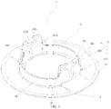
- FIG. 3 is a schematic structure diagram of a face ring according to an example of the present disclosure.
- FIG. 4 is a schematic structure diagram of a luminaire body mounted downwardly in a face ring according to an example of the present disclosure
- FIG. 5 is a partial structure diagram of FIG. 4 ;
- FIG. 6 is a schematic structure diagram of a lighting device according to an example of the present disclosure.
- FIG. 7 is a schematic structure diagram of a luminaire body rotated to one side within a face ring
- FIG. 8 is a schematic structure diagram of a luminaire body rotated to the other side within a face ring
- FIG. 9 is a schematic structure diagram of a luminaire body mounted downwardly in a face ring according to another example of the present disclosure.
- FIG. 10 is a partial structural diagram of FIG. 9 ;
- FIG. 11 is a stereogram of a face ring according to an example of the present disclosure.
- FIG. 12 is an internal view of a housing according to an example of the present disclosure.
- FIG. 13 is an external view of a housing according to an example of the present disclosure.
- FIG. 14 is a stereogram of a spot lamp according to another example of the present disclosure.
- An LED spot lamp may include a light-emitting assembly, a lamp housing, and a face ring.
- the light-emitting assembly may include a lamp and may be mounted in the lamp housing.
- the face ring may have a mounting space therein. The face ring may be placed around the lamp housing, and the lamp housing can swing by a particular angle in the mounting space.
- the lamp housing may be rotated to adjust the irradiation angle of the LED spot lamp.
- the lamp housing and the face ring of the spot lamp are connected by means of an interference fit between a rotating shaft disposed on the lamp housing and a shaft hole formed in the face ring.
- An existing face ring may be made of a plastic material which has certain elastic deformation capacity.
- the material of a face ring would be an important factor for a customer to choose a commercially available LED spot lamp.
- metal face rings are more popular.
- the existing connection manner of a lamp housing and a face ring requires the face ring to have certain elastic deformation capability. That is, in view of the existing connection manner of a lamp housing and a face ring, the face ring cannot be made of a hard material such as a metal.
- an example of the present disclosure provides a luminaire body 1 , including: a lamp 11 , and at least one rotating shaft 12 disposed on a sidewall 111 of the lamp 11 .
- the rotating shaft 12 includes an elastic mechanism 122 .
- One end of the elastic mechanism 122 serves as a connection end 1221 which is disposed on the sidewall 111 of lamp 11 .
- At least one first rabbet 123 is formed in the elastic mechanism 122 in a direction away from the connection end 1221 .
- the luminaire body 1 may be designed into an integrated structure or a split structure, and the former may have the advantages of simple process and low cost.
- the rotating shaft 12 further includes a mounting part 121 .
- the mounting part 121 is disposed on the sidewall 111 of the lamp 11 and the connection end 1221 is disposed on the mounting part 121 .
- the rotating shaft 12 having the elastic mechanism 122 is disposed on the lamp 11 and the elastic mechanism 122 is allowed to snap into the face ring 2 as shown in FIG. 3 .
- the elastic mechanism 122 is disposed on the lamp 11 , if there is a need for a stabilizing mechanism such as a spring on the face ring 2 , the luminaire body 1 does not need to be changed. That is, the luminaire body 1 has good applicability.
- the first rabbet 123 is a C-shaped rabbet that forms a groove in the elastic mechanism 122 in the direction away from the connection end 1221 .
- an open end 1231 of the C-shaped rabbet has a width a of 2 ⁇ 0.2 mm in a direction perpendicular to a direction far away from the connection end 1221 .
- the elastic mechanism 122 has an outer diameter r of 5 to 5.5 mm.
- a rabbet is a recess or a groove cut into the edge of a part of the luminaire body, and the cross section of a rabbet at least includes an open edge.
- a second limiting unit 126 is disposed on the proximal end 124 of the outer wall of the elastic mechanism 122 to limit a rotation angle ⁇ of the rotating shaft 12 .
- the rotation angle is typically set within a range of 20 to 35°, and the second limiting unit 126 may change in width with the rotation angle ⁇ . For example, when the rotation angle is set to 20°, the second limiting unit 126 has a maximum width; and when the rotation angle is set to 35°, the second limiting unit 126 has a minimal width.
- first rabbets 123 are provided along a direction away from the sidewall 111 of the lamp 11 .
- a circular rabbet 1233 is formed in the center of the elastic mechanism 122 .
- Three grooves 1234 are formed in a direction from the circular rabbet 1233 toward the outer wall of the elastic mechanism 122 .
- the three grooves 1234 form a Y-shaped rabbet.
- the elastic mechanism 122 has an outer diameter r of 5 to 5.5 mm.
- the groove 1234 has a width d of 1 to 1.2 mm in a direction perpendicular to a direction far away from the connection end 1221 .
- the luminaire body 1 further includes a first limiting unit 125 disposed at the other end of the elastic mechanism 122 .
- the first limiting unit 125 and the mounting part 121 fit the inner wall and the outer wall of the face ring 2 , respectively, and serve for fastening the elastic mechanism 122 to the face ring 2 , preventing deformation of the face ring 2 due to an external force when the luminaire body 1 is in contact with the face ring 2 .
- the first limiting unit 125 is a fan-shaped mechanism having two ends connected to two ends of the opening of the C-shaped rabbet, respectively.
- the first limiting unit 125 is a bump extending in a direction from the end of the C-shaped rabbet to the mounting part 121 .
- the fan-shaped mechanism is notched in a direction away from the opening of the C-shaped rabbet. In one example of the present disclosure, as shown in FIG. 1 , the fan-shaped mechanism is notched along the outer wall of the rotating shaft 12 so that the first limiting unit 125 is divided into two fan-shaped mechanisms.
- the first limiting unit 125 is a circular ring mechanism for being sleeved on the other end of the elastic mechanism 122 .
- An opening in conformance with the Y-shaped rabbet is formed in the circular ring mechanism.
- two rotating shafts are disposed on the sidewall 111 of the lamp 11 in a 180° axisymmetric manner.
- the mounting stability of the luminaire body 1 and the face ring 2 is improved.
- more than two rotating shafts 2 may be arranged on the sidewall 111 of the lamp 11 in the form of a circular array.
- the luminaire body 1 is made of plastics.
- the preset application provides a face ring 2 having one end to be sleeved on the luminaire body 1 and the other end to be fixed to a mounting face 3 .
- the face ring 2 includes: a face ring body 21 and an inner ring surface 22 .
- the inner ring surface 22 has a circular ring structure protruding from the face ring body 21 in a direction away from the mounting face 3 , and the inner ring surface 22 and the face ring body 21 form a holding part 23 for mounting the luminaire body 1 .
- At least one connection unit 24 is disposed on the outer wall of the inner ring surface 22 , and the connection unit 24 is connected to the rotating shaft 12 .
- the face ring 2 may have an integrated structure and thus can be produced by a simple process with low cost.
- connection unit 24 includes two clamping parts 241 extending along an end face 221 of the inner ring surface 22 in a direction away from the mounting face 3 .
- the two clamping parts 241 and the inner ring surface 22 form a second rabbet 25 which is connected to the rotating shaft 12 .
- the second rabbet 25 is a groove formed between the two clamping parts 241 and the inner ring surface 22 , and the second rabbet 25 includes an opening between the two clamping parts 241 .
- an inclined guide face 2412 is formed on an inner wall 2411 , on the side fitting the rotating shaft 12 , of the clamping part 241 ; a mating hole 242 is formed in the bottom of the second rabbet 25 ; and two ends, far away from the mounting face 3 , of the mating hole 242 are connected to ends of the two inclined guide faces 2412 , respectively.
- the two ends of the mating hole 242 are connected to the ends of two inclined guide faces 2412 through two transition faces 2413 .
- an included angle ⁇ between the two inclined guide faces 2412 is 30 ⁇ 5°.
- a length of a circular arc at the opening of the mating hole 242 is smaller than 1 ⁇ 2 of a circumference of the mating hole.
- the size of the opening of the mating hole 242 is smaller than the diameter of the mating hole 242 , so that the mating hole 242 plays a role in holding down the elastic mechanism 122 , allowing the elastic mechanism 122 to be arranged in the mating hole 242 more stably.
- spring mounting grooves 243 are formed between the ends of the two inclined guide faces 2412 and the top ends of the clamping parts 241 in a direction far away from the mounting face 3 .
- the face ring 2 may be made of a metal material or plastics.
- the present disclosure provides a lighting device includes a luminaire body 1 , and a face ring 2 attachable to the luminaire body 1 .
- the mounting part 121 of the luminaire body 1 fits an inner wall of the inner ring surface 22
- the first limiting unit 125 of the luminaire body 1 fits an outer wall of the inner ring surface 22
- the elastic mechanism 122 is arranged in the mating hole 242 .
- the elastic mechanism 122 will undergo a deformation under the action of the clamping parts 241 , and thus may be clamped by the clamping parts 241 , so that the face ring 2 is sleeved on the sidewall 111 of the lamp 11 , thereby achieving rapid connection of the face ring 2 and the luminaire body 1 .
- the rotating shaft 12 is disengaged from the clamping parts 241 under the action of an external force, thereby achieving rapid dismounting of the face ring 2 from luminaire body 1 .
- the luminaire body disclosed in this example of the present disclosure includes a lamp, and at least one rotating shaft disposed on the sidewall of the lamp.
- the elastic mechanism When mounting the luminaire body on the face ring, the elastic mechanism is pressed between the clamping parts of the face ring under the action of an external force. The elastic mechanism will undergo a deformation under the action of the clamping parts, and thus may be clamped by the clamping parts, so that the face ring is sleeved on the sidewall of the lamp, thereby achieving rapid connection of the face ring and the luminaire body.
- the rotating shaft is disengaged from the clamping parts under the action of an external force, thereby achieving rapid dismounting of the face ring from luminaire body.
- the lamp housing assembly includes a face ring 20 and a housing 10 .
- the face ring 20 has a first mounting space 210 therein.
- Two first sliding faces 230 are formed opposite to each other on an outer surface of the face ring 20 .
- a second mounting space 220 is formed on the first sliding face 23 .
- the housing 10 is disposed in the first mounting space 210 .
- Two rotating shafts 1220 are connected to the housing 10 , and each rotating shaft 1220 is in running fit with the corresponding second mounting space 22 .
- An adjusting block 1210 is disposed on the rotating shaft 122 .
- the adjusting block 1210 presses against the corresponding first sliding face 23 .
- the lamp housing assembly provided in this example has the following advantages: when there is a need to adjust the angle of the housing 10 , the housing 10 may be rotated, causing the adjusting blocks 1210 to rotate relative to the first sliding faces 23 . When the irradiation angle is adjusted to an appropriate angle, the housing 10 is released. Due to the elasticity of an elastic body 12 , the adjusting blocks 1210 are caused to press against the first sliding faces 23 , and there is a damping force between each adjusting block and each first sliding face 23 , which keeps the housing 10 in the adjusted position after the housing 10 is released.
- the lamp housing assembly provided in this example permits the adjustment of the angle of the housing 10 based on the running fit between the adjusting blocks 1210 and the first sliding faces 230 and the damping force between the adjusting blocks 1210 and the first sliding faces 23 .
- the face ring 20 may be made of an elastic material, or a hard material such as a metal.
- the face ring 20 includes a tubular body 250 and an annular body 26 .
- the tubular body 250 is connected to the annular body 26 , and the inner cavity of the tubular body 250 and a central hole of the annular body 26 define a first mounting space 210 passing through the face ring 20 .
- Two first sliding faces 230 are formed on the outer surface of the tubular body 250 .
- a second mounting space 220 is formed on each of the two first sliding faces 23 .
- the housing 10 has a mounting cavity 110 therein.
- the mounting cavity 110 is used for mounting a light-emitting assembly.
- the housing 10 is disposed in the first mounting space 210 .
- the rotating shaft 1220 and the adjusting block 1210 form an elastic body 12 .
- Two elastic bodies 120 are connected to the outer surface of the housing 10 .
- the rotating shaft 1220 is in running fit with the second mounting space 22 .
- An inner end of the rotating shaft 1220 extends through the second mounting space 220 to be connected to the housing 10 .
- the adjusting block 1210 is disposed at an outer end of the rotating shaft 122 .
- the elastic body 120 may include the rotating shaft 122 , the adjusting block 1210 and a spring such that the adjusting block 1210 can elastically press against the first sliding face 23 . With the combination of the rotating shaft 122 , the adjusting block 1210 and the spring, the adjusting block 1210 is allowed to elastically press against the first sliding face 23 .
- the elastic body 120 may also be made, in part, of an elastic material, thus allowing the adjusting block 1210 to elastically press against the first sliding face 23 .
- the rotating shaft 1220 is made of an elastic material, while the adjusting block 1210 is made of a non-elastic material. Since the rotating shaft 1220 needs to be in running fit with the second mounting space 22 , the rotating shaft 1220 is required to have rigidity and elasticity.
- the adjusting block 1210 is made of an elastic material, while the rotating shaft 1220 is made of a non-elastic material.
- the elastic body 120 in this example is entirely made of an elastic material. That is, both of the rotating shaft 1220 and the adjusting block 1210 are made of an elastic material, allowing the elastic body 120 in this example to be molded integrally and thus reducing the steps and cost of assembling.
- the elastic body 120 in this example and the housing 10 are integrally formed by injection molding, Since plastics have rigidity and elasticity, the elastic body 120 is endowed with rigidity and elasticity, allowing the rotating shaft 1220 to be in running fit with the second mounting space 220 and the adjusting block 1210 to press against the first sliding face 23 .
- the first sliding face 230 may be a circular-arc-shaped face.
- the adjusting block 1210 is capable of rotating on the first sliding face 230 because the elastic body 120 has elasticity.
- the first sliding face 230 in this example is a flat face which is easy to manufacture.
- the face, oriented toward the first sliding face 23 , of the adjusting block 1210 is also formed into a flat face, i.e., the face, to be in running fit with the first sliding face 23 , of the adjusting block 1210 is also formed into a flat face.
- the adjusting block 1210 needs to be reduced, so that the friction between the two faces in running fit with each other is reduced and the requirement on the surface accuracy of the faces is lowered.
- the adjusting block 1210 needs to be limited on the first sliding face 230 by the second mounting space 22 , the adjusting block 1210 cannot be small in size.
- a protrusion 1212 is formed on the face, oriented toward the housing 10 , of the adjusting block 1210 in this example.
- the face, oriented toward the housing 10 , of the protrusion 1212 is a second sliding face 12121 .
- the second sliding face 12121 is in running fit with the first sliding face 23 .
- forming the protrusion 1212 on the face, oriented toward the housing 10 , of the adjusting block 1210 and forming the second sliding face 12121 on the protrusion 1212 may produce the following beneficial effects: 1, the area of the second sliding face 12121 may be small to reduce the friction between the second sliding face 12121 and the first sliding face 23 , allowing the second sliding face 12121 and the first sliding face 230 to abut against each other and to rotate relative to each other without getting stuck. 2.
- the adjusting block 1210 can be limited on the first sliding face 230 by the second mounting space 220 without being reduced in size.
- the elastic body 120 in this example may be connected to the housing 10 by means of a connecting piece, or may be integrated with the housing 10 .
- the second mounting space 220 formed on the first sliding face 230 may be of a closed hole structure, or may be of a groove structure with an open end.
- the adjusting block 1210 When the second mounting space 220 is of the hole structure, it is required that the adjusting block 1210 has a greater size than the second mounting space 220 because the adjusting block 1210 needs to be limited on the first sliding face 230 by the second mounting space 22 . That is, the adjusting block 1210 cannot pass through the second mounting space 22 . In this case, the elastic body 120 cannot be integrated with the housing 10 . In other words, when the second mounting space 220 is of the hole structure, the elastic body 120 is assembled with the housing 10 by means of a connecting piece.
- the elastic body 120 may be connected to the housing 10 by means of a connecting piece, or may be integrated with the housing 10 .
- the second mounting space 220 in this example is of the groove structure.
- the tubular body 250 includes a first tubular end 251 and a second tubular end 252 .
- the first tubular end 251 is connected to the annular body 26 .
- the second mounting space 220 includes a first end 2210 and a second end 222 .
- the first end 2210 which is an open end, is located on the second tubular end 252
- the second end 222 which is a closed end, is located between the first tubular end 251 and the second tubular end 252 .
- the housing 10 is moved from the second tubular end 252 toward the first tubular end 251 to be mounted in the first mounting space 210 of the face ring 20 .
- the second mounting space 220 is arranged along an axis of the face ring 20 .
- the length direction of the adjusting block 1210 in this example is perpendicular to the axis of the face ring 20 .
- the adjusting block 1210 can be limited by the second mounting space 220 with a small size, and the material of the adjusting block 1210 is saved.
- the second mounting space 220 in this example may be the same or different in size from the first end 2210 to the second end 222 as long as it can receive the middle portion of the rotating shaft 1220 and limit the adjusting block 121 .
- the second mounting space 220 in this example is gradually reduced in size in a direction from the first end 2210 to the second end 222 to form a guide structure that facilitates the entry of the rotating shaft 1220 into the second mounting space 22 .
- the rotating shaft 1220 is supported by the second end 222 of the second mounting space 22 .
- the surface of the second end 222 in this example is a circular-arc-shaped surface.
- the rotating shaft 1220 is in running fit with the second end 222 .
- the rotating shaft 122 , the adjusting block 1210 and the housing 10 are integrally formed by injection molding.
- a guide block 240 is disposed on the first sliding face 230 in this example.
- the face, oriented toward the second mounting space 22 , of the guide block 24 is a first guide face 241
- the face, opposite to the first guide face 241 , of the adjusting block 1210 is a second guide face 1211 .
- Both of the first guide face 2410 and the second guide face 1211 are circular-arc-shaped faces.
- the first guide face 2410 is in sliding fit with the second guide face 1211 .
- One or two guide blocks 240 may be used. In case of one guide block 24 , the effect of guiding the rotation of the adjusting block 1210 can still be achieved. To further enhance the guiding effect, two guide blocks 240 are used in this example, which are located oppositely on two sides of the second mounting space 22 , respectively. Correspondingly, the faces, opposite to two first guide faces 241 , of the adjusting block 1210 are both second guide faces 1211 .
- each of the guide block 240 and the adjusting block 1210 is required to have a great thickness so as to ensure a large area of fit between the first guide face 2410 of the guide block 240 and the second guide face 1211 of the adjusting block 121 , thus resulting in increased cost.
- the end, oriented toward the first guide face 241 , of the adjusting block 1210 is an outer end, and the protrusion 1212 is disposed on the outer end of the adjusting block 121 .
- the face, oriented toward the first guide face 241 , of the protrusion 1212 forms part or all of the second guide face 1211 .
- the face, oriented toward the first guide face 241 , of the protrusion 1212 forms part of the second guide face 1211 .
- the rotating shaft 122 , the adjusting block 121 , the protrusion 1212 and the housing 10 are integrally formed by injection molding.
- an example of the present disclosure discloses a spot lamp 100 .
- the spot lamp 100 includes a light-emitting assembly and the lamp housing assembly as described above.
- the light-emitting assembly includes a lamp.
- the light-emitting assembly is mounted in the mounting cavity 11 .
- the annular body 26 is located at a light-exiting end of the light-emitting assembly.
- the housing 10 has a housing mounting end 13 which is open and communicated with the mounting cavity 11 .
- the light-emitting assembly is mounted in the mounting cavity 110 via the housing mounting end 13 , and the lamp is disposed at the housing mounting end 13 .
- the housing mounting end 13 is the light-exiting side.
- the housing 10 After the housing 10 is assembled with the face ring 20 , the housing 10 is capable of rotating in the first mounting space 210 of the face ring 20 . Since the first mounting space 210 extends through the face ring 20 , the illumination of the lamp would not be blocked.
- the end, connected to the tubular body 250 , of the annular body 26 is a first annular end, while the other end thereof is a second annular end. Light emitted by the lamp goes out from the center of the second annular end of the annular body 26 .
- the spot lamp 100 in this example has the following advantages: when there is a need to adjust the irradiation angle of the spot lamp 100 , the housing 10 may be rotated, causing the adjusting blocks 1210 to rotate relative to the first sliding faces 23 . When the irradiation angle is adjusted to an appropriate angle, the housing 10 is released. In this case, the adjusting blocks 1210 are caused to press against the first sliding faces 23 , and there is a damping force between the adjusting block and the first sliding face 23 . The damping force can keep the irradiation angle of the spot lamp 100 in the adjusted position after the housing 10 is released.
- the spot lamp 100 in this example permits the adjustment of the irradiating angle of the spot lamp 100 based on the running fit between the adjusting blocks 1210 and the first sliding faces 230 and the damping force between the adjusting blocks 1210 and the first sliding faces 23 .
- the face ring 20 may be made of an elastic material, or a hard material such as a metal.
- the entire spot lamp 100 can be mounted on the ceiling by mounting the face ring 20 on the ceiling.
- the spot lamp provided in the present disclosure has the following advantages: when there is a need to adjust the irradiation angle of the spot lamp, the housing may be rotated, causing the adjusting blocks to rotate relative to the first sliding faces. When the irradiation angle is adjusted to an appropriate angle, the housing is released. In this case, the adjusting blocks are caused to press against the first sliding faces, thereby inducing a damping force between the adjusting blocks and the first sliding faces. The damping force can keep the irradiation angle of the spot lamp in the adjusted position after the housing is released.
- the spot lamp provided in the present disclosure permits the adjustment of the irradiating angle of the spot lamp based on the running fit between the adjusting blocks and the first sliding faces and the damping force between the adjusting blocks and the first sliding faces.
- the face ring may be made of an elastic material, or a hard material such as a metal.
- the present disclosure provides following examples.
- an example of the present disclosure provides a luminaire body, including: a lamp, and at least one rotating shaft disposed on a sidewall of the lamp.
- One end of the elastic mechanism serves as a connection end which is disposed on the sidewall of the lamp.
- At least one first rabbet is provided in the elastic mechanism in a direction away from the connection end.
- the present disclosure provides a face ring having one end configured to be sleeved on the luminaire body as described above and the other end configured to be fixed to a mounting face.
- the face ring includes: a face ring body and an inner ring surface.
- the inner ring surface has a circular ring structure protruding from the face ring body in a direction away from the mounting face, and the inner ring surface and the face ring body form a holding part for mounting the luminaire body.
- At least one connection unit is disposed on an outer wall of the inner ring surface, and the connection unit is configured to be connected to the rotating shaft.
- the present disclosure provides a lighting device including the luminaire body as described above, and the above-described face ring which is attachable to the luminaire body.
- the present disclosure provides a lamp housing assembly including: a face ring having a first mounting space therein, two first sliding faces are formed opposite to each other on an outer surface of the face ring, and a second mounting space is provided on the first sliding face; and a housing disposed in the first mounting space.
- Two rotating shafts connected to the housing, and each rotating shaft is in running fit with the corresponding second mounting space.
- An adjusting block is disposed on each of the rotating shafts. The adjusting block presses against the corresponding first sliding face.
- the present disclosure provides a spot lamp including a light-emitting assembly and the above-described lamp-housing assembly.
- the light-emitting assembly includes a lamp and is mounted in the mounting cavity.
- the present disclosure may include dedicated hardware implementations such as application specific integrated circuits, programmable logic arrays and other hardware devices.
- the hardware implementations can be constructed to implement one or more of the methods described herein. Examples that may include the apparatus and systems of various implementations can broadly include a variety of electronic and computing systems.
- One or more examples described herein may implement functions using two or more specific interconnected hardware modules or devices with related control and data signals that can be communicated between and through the modules, or as portions of an application-specific integrated circuit. Accordingly, the system disclosed may encompass software, firmware, and hardware implementations.
- module may include memory (shared, dedicated, or group) that stores code or instructions that can be executed by one or more processors.
- the module refers herein may include one or more circuit with or without stored code or instructions.
- the module or circuit may include one or more components that are connected.
Landscapes
- Engineering & Computer Science (AREA)
- General Engineering & Computer Science (AREA)
- Non-Portable Lighting Devices Or Systems Thereof (AREA)
- Fastening Of Light Sources Or Lamp Holders (AREA)
Abstract
Description
Claims (20)
Applications Claiming Priority (5)
| Application Number | Priority Date | Filing Date | Title |
|---|---|---|---|
| CN201920057937.0 | 2019-01-14 | ||
| CN201920057937.0U CN209245846U (en) | 2019-01-14 | 2019-01-14 | Lamp housing component and shot-light |
| CN201920428616.7U CN209445303U (en) | 2019-03-29 | 2019-03-29 | A kind of lamp main body, face ring and lighting device |
| CN201920428616.7 | 2019-03-29 | ||
| PCT/CN2019/130411 WO2020147579A1 (en) | 2019-01-14 | 2019-12-31 | Lamp main body, surface ring, and lighting device |
Related Parent Applications (1)
| Application Number | Title | Priority Date | Filing Date |
|---|---|---|---|
| PCT/CN2019/130411 Continuation WO2020147579A1 (en) | 2019-01-14 | 2019-12-31 | Lamp main body, surface ring, and lighting device |
Publications (2)
| Publication Number | Publication Date |
|---|---|
| US20210341133A1 US20210341133A1 (en) | 2021-11-04 |
| US11454377B2 true US11454377B2 (en) | 2022-09-27 |
Family
ID=71613285
Family Applications (1)
| Application Number | Title | Priority Date | Filing Date |
|---|---|---|---|
| US17/374,951 Active US11454377B2 (en) | 2019-01-14 | 2021-07-13 | Luminaire body, face ring and lighting device |
Country Status (2)
| Country | Link |
|---|---|
| US (1) | US11454377B2 (en) |
| WO (1) | WO2020147579A1 (en) |
Families Citing this family (5)
| Publication number | Priority date | Publication date | Assignee | Title |
|---|---|---|---|---|
| USD843642S1 (en) * | 2015-05-03 | 2019-03-19 | Lucifer Lighting Company | Cylindrical fixture mount |
| CN114076278A (en) * | 2021-09-13 | 2022-02-22 | 江门市辉邦照明有限公司 | Angle-adjustable full-function intelligent control illuminating lamp |
| CN114151749A (en) * | 2021-11-19 | 2022-03-08 | 苏州欧普照明有限公司 | Lamp set |
| CN114321783A (en) * | 2021-12-01 | 2022-04-12 | 苏州欧普照明有限公司 | Lamp shell assembly and lamp applying same |
| CN115641788B (en) * | 2022-11-01 | 2026-01-09 | 上海金标文化创意股份有限公司 | An advertising light box |
Citations (7)
| Publication number | Priority date | Publication date | Assignee | Title |
|---|---|---|---|---|
| US20040252508A1 (en) | 2003-06-11 | 2004-12-16 | Benny Lin | Lamp structure improved for assembling |
| CN206036692U (en) | 2016-08-30 | 2017-03-22 | 欧普照明股份有限公司 | LED lighting device |
| EP3153767A1 (en) * | 2015-10-05 | 2017-04-12 | OSRAM GmbH | A lighting device and corresponding method |
| CN207334410U (en) | 2017-08-22 | 2018-05-08 | 漳州立达信光电子科技有限公司 | A 3D rotating downlight |
| CN208558987U (en) | 2018-06-11 | 2019-03-01 | 上海恩坦华汽车部件有限公司 | Sink behind sunroof |
| CN209245846U (en) | 2019-01-14 | 2019-08-13 | 欧普照明股份有限公司 | Lamp housing component and shot-light |
| CN209445303U (en) | 2019-03-29 | 2019-09-27 | 欧普照明股份有限公司 | A kind of lamp main body, face ring and lighting device |
-
2019
- 2019-12-31 WO PCT/CN2019/130411 patent/WO2020147579A1/en not_active Ceased
-
2021
- 2021-07-13 US US17/374,951 patent/US11454377B2/en active Active
Patent Citations (7)
| Publication number | Priority date | Publication date | Assignee | Title |
|---|---|---|---|---|
| US20040252508A1 (en) | 2003-06-11 | 2004-12-16 | Benny Lin | Lamp structure improved for assembling |
| EP3153767A1 (en) * | 2015-10-05 | 2017-04-12 | OSRAM GmbH | A lighting device and corresponding method |
| CN206036692U (en) | 2016-08-30 | 2017-03-22 | 欧普照明股份有限公司 | LED lighting device |
| CN207334410U (en) | 2017-08-22 | 2018-05-08 | 漳州立达信光电子科技有限公司 | A 3D rotating downlight |
| CN208558987U (en) | 2018-06-11 | 2019-03-01 | 上海恩坦华汽车部件有限公司 | Sink behind sunroof |
| CN209245846U (en) | 2019-01-14 | 2019-08-13 | 欧普照明股份有限公司 | Lamp housing component and shot-light |
| CN209445303U (en) | 2019-03-29 | 2019-09-27 | 欧普照明股份有限公司 | A kind of lamp main body, face ring and lighting device |
Non-Patent Citations (4)
| Title |
|---|
| International Search Report of PCT Application No. PCT/CN2019/130411 dated Mar. 26, 2020 with English translation, (4p). |
| Search translation of CP 207334410. (Year: 2018). * |
| Search translation of CP 209245846. (Year: 2019). * |
| Search translation of CP 209445303. (Year: 2019). * |
Also Published As
| Publication number | Publication date |
|---|---|
| US20210341133A1 (en) | 2021-11-04 |
| WO2020147579A1 (en) | 2020-07-23 |
Similar Documents
| Publication | Publication Date | Title |
|---|---|---|
| US11454377B2 (en) | Luminaire body, face ring and lighting device | |
| US9032590B2 (en) | Rotating mechanism and electronic device with same | |
| US20140049967A1 (en) | Light beam adjusting structure for light emitting diode (led) lamp | |
| US11473772B2 (en) | Quick assembling structure for ceiling fan with lamp | |
| US20190093861A1 (en) | Zoom LED Lamp | |
| US20210116119A1 (en) | Lighting assembly and lighting lamp | |
| US20250198607A1 (en) | Angle-adjustable lamp | |
| JP5717516B2 (en) | lighting equipment | |
| US11333328B1 (en) | Lampshade module capable of replacing optical projection elements | |
| KR101645397B1 (en) | Lighting that irradiation angle of light is regulated | |
| US20140000063A1 (en) | Adjustable unit for table lamp | |
| JP5971846B2 (en) | Straight tube LED lamp | |
| US10683995B1 (en) | Lighting apparatus | |
| US8708510B2 (en) | Rotatable lighting apparatus | |
| CN105114869A (en) | LED lamp | |
| CN209245846U (en) | Lamp housing component and shot-light | |
| US11713856B2 (en) | Lighting lamp | |
| CN217540445U (en) | Illumination angle adjusting structure and lamp | |
| BR112017009874A2 (en) | vehicle door mirror | |
| US11473740B2 (en) | Lighting fixture | |
| CN210979444U (en) | Rotating lamps | |
| CN217737128U (en) | Rotating structure and lamp thereof | |
| JP2017174785A (en) | Luminaire | |
| KR20110075666A (en) | LED module lighting device with angle adjustment means | |
| US20260022819A1 (en) | Wall lamp |
Legal Events
| Date | Code | Title | Description |
|---|---|---|---|
| FEPP | Fee payment procedure |
Free format text: ENTITY STATUS SET TO UNDISCOUNTED (ORIGINAL EVENT CODE: BIG.); ENTITY STATUS OF PATENT OWNER: LARGE ENTITY |
|
| AS | Assignment |
Owner name: SUZHOU OPPLE LIGHTING CO., LTD., CHINA Free format text: ASSIGNMENT OF ASSIGNORS INTEREST;ASSIGNOR:XUE, YONG;REEL/FRAME:056853/0455 Effective date: 20210713 Owner name: OPPLE LIGHTING CO., LTD., CHINA Free format text: ASSIGNMENT OF ASSIGNORS INTEREST;ASSIGNOR:XUE, YONG;REEL/FRAME:056853/0455 Effective date: 20210713 |
|
| STPP | Information on status: patent application and granting procedure in general |
Free format text: DOCKETED NEW CASE - READY FOR EXAMINATION |
|
| STPP | Information on status: patent application and granting procedure in general |
Free format text: NON FINAL ACTION MAILED |
|
| STPP | Information on status: patent application and granting procedure in general |
Free format text: RESPONSE TO NON-FINAL OFFICE ACTION ENTERED AND FORWARDED TO EXAMINER |
|
| STPP | Information on status: patent application and granting procedure in general |
Free format text: FINAL REJECTION MAILED |
|
| STPP | Information on status: patent application and granting procedure in general |
Free format text: RESPONSE AFTER FINAL ACTION FORWARDED TO EXAMINER |
|
| STPP | Information on status: patent application and granting procedure in general |
Free format text: NOTICE OF ALLOWANCE MAILED -- APPLICATION RECEIVED IN OFFICE OF PUBLICATIONS |
|
| STPP | Information on status: patent application and granting procedure in general |
Free format text: PUBLICATIONS -- ISSUE FEE PAYMENT VERIFIED |
|
| STCF | Information on status: patent grant |
Free format text: PATENTED CASE |