US11450983B2 - Housing of high-speed transmission connector and high-speed transmission connector - Google Patents
Housing of high-speed transmission connector and high-speed transmission connector Download PDFInfo
- Publication number
- US11450983B2 US11450983B2 US17/175,165 US202117175165A US11450983B2 US 11450983 B2 US11450983 B2 US 11450983B2 US 202117175165 A US202117175165 A US 202117175165A US 11450983 B2 US11450983 B2 US 11450983B2
- Authority
- US
- United States
- Prior art keywords
- side wall
- frontage
- holes
- side walls
- bottom plate
- Prior art date
- Legal status (The legal status is an assumption and is not a legal conclusion. Google has not performed a legal analysis and makes no representation as to the accuracy of the status listed.)
- Active
Links
Images


Classifications
-
- H—ELECTRICITY
- H01—ELECTRIC ELEMENTS
- H01R—ELECTRICALLY-CONDUCTIVE CONNECTIONS; STRUCTURAL ASSOCIATIONS OF A PLURALITY OF MUTUALLY-INSULATED ELECTRICAL CONNECTING ELEMENTS; COUPLING DEVICES; CURRENT COLLECTORS
- H01R13/00—Details of coupling devices of the kinds covered by groups H01R12/70 or H01R24/00 - H01R33/00
- H01R13/46—Bases; Cases
- H01R13/502—Bases; Cases composed of different pieces
-
- H—ELECTRICITY
- H01—ELECTRIC ELEMENTS
- H01R—ELECTRICALLY-CONDUCTIVE CONNECTIONS; STRUCTURAL ASSOCIATIONS OF A PLURALITY OF MUTUALLY-INSULATED ELECTRICAL CONNECTING ELEMENTS; COUPLING DEVICES; CURRENT COLLECTORS
- H01R13/00—Details of coupling devices of the kinds covered by groups H01R12/70 or H01R24/00 - H01R33/00
- H01R13/46—Bases; Cases
- H01R13/50—Bases; Cases formed as an integral body
-
- H—ELECTRICITY
- H01—ELECTRIC ELEMENTS
- H01R—ELECTRICALLY-CONDUCTIVE CONNECTIONS; STRUCTURAL ASSOCIATIONS OF A PLURALITY OF MUTUALLY-INSULATED ELECTRICAL CONNECTING ELEMENTS; COUPLING DEVICES; CURRENT COLLECTORS
- H01R12/00—Structural associations of a plurality of mutually-insulated electrical connecting elements, specially adapted for printed circuits, e.g. printed circuit boards [PCB], flat or ribbon cables, or like generally planar structures, e.g. terminal strips, terminal blocks; Coupling devices specially adapted for printed circuits, flat or ribbon cables, or like generally planar structures; Terminals specially adapted for contact with, or insertion into, printed circuits, flat or ribbon cables, or like generally planar structures
- H01R12/70—Coupling devices
- H01R12/7005—Guiding, mounting, polarizing or locking means; Extractors
- H01R12/7011—Locking or fixing a connector to a PCB
- H01R12/7052—Locking or fixing a connector to a PCB characterised by the locating members
-
- H—ELECTRICITY
- H01—ELECTRIC ELEMENTS
- H01R—ELECTRICALLY-CONDUCTIVE CONNECTIONS; STRUCTURAL ASSOCIATIONS OF A PLURALITY OF MUTUALLY-INSULATED ELECTRICAL CONNECTING ELEMENTS; COUPLING DEVICES; CURRENT COLLECTORS
- H01R12/00—Structural associations of a plurality of mutually-insulated electrical connecting elements, specially adapted for printed circuits, e.g. printed circuit boards [PCB], flat or ribbon cables, or like generally planar structures, e.g. terminal strips, terminal blocks; Coupling devices specially adapted for printed circuits, flat or ribbon cables, or like generally planar structures; Terminals specially adapted for contact with, or insertion into, printed circuits, flat or ribbon cables, or like generally planar structures
- H01R12/70—Coupling devices
- H01R12/71—Coupling devices for rigid printing circuits or like structures
- H01R12/712—Coupling devices for rigid printing circuits or like structures co-operating with the surface of the printed circuit or with a coupling device exclusively provided on the surface of the printed circuit
- H01R12/716—Coupling device provided on the PCB
-
- G—PHYSICS
- G01—MEASURING; TESTING
- G01B—MEASURING LENGTH, THICKNESS OR SIMILAR LINEAR DIMENSIONS; MEASURING ANGLES; MEASURING AREAS; MEASURING IRREGULARITIES OF SURFACES OR CONTOURS
- G01B21/00—Measuring arrangements or details thereof, where the measuring technique is not covered by the other groups of this subclass, unspecified or not relevant
- G01B21/02—Measuring arrangements or details thereof, where the measuring technique is not covered by the other groups of this subclass, unspecified or not relevant for measuring length, width, or thickness
-
- H—ELECTRICITY
- H01—ELECTRIC ELEMENTS
- H01R—ELECTRICALLY-CONDUCTIVE CONNECTIONS; STRUCTURAL ASSOCIATIONS OF A PLURALITY OF MUTUALLY-INSULATED ELECTRICAL CONNECTING ELEMENTS; COUPLING DEVICES; CURRENT COLLECTORS
- H01R12/00—Structural associations of a plurality of mutually-insulated electrical connecting elements, specially adapted for printed circuits, e.g. printed circuit boards [PCB], flat or ribbon cables, or like generally planar structures, e.g. terminal strips, terminal blocks; Coupling devices specially adapted for printed circuits, flat or ribbon cables, or like generally planar structures; Terminals specially adapted for contact with, or insertion into, printed circuits, flat or ribbon cables, or like generally planar structures
- H01R12/70—Coupling devices
- H01R12/71—Coupling devices for rigid printing circuits or like structures
- H01R12/72—Coupling devices for rigid printing circuits or like structures coupling with the edge of the rigid printed circuits or like structures
- H01R12/73—Coupling devices for rigid printing circuits or like structures coupling with the edge of the rigid printed circuits or like structures connecting to other rigid printed circuits or like structures
-
- H—ELECTRICITY
- H01—ELECTRIC ELEMENTS
- H01R—ELECTRICALLY-CONDUCTIVE CONNECTIONS; STRUCTURAL ASSOCIATIONS OF A PLURALITY OF MUTUALLY-INSULATED ELECTRICAL CONNECTING ELEMENTS; COUPLING DEVICES; CURRENT COLLECTORS
- H01R2201/00—Connectors or connections adapted for particular applications
- H01R2201/20—Connectors or connections adapted for particular applications for testing or measuring purposes
-
- H—ELECTRICITY
- H01—ELECTRIC ELEMENTS
- H01R—ELECTRICALLY-CONDUCTIVE CONNECTIONS; STRUCTURAL ASSOCIATIONS OF A PLURALITY OF MUTUALLY-INSULATED ELECTRICAL CONNECTING ELEMENTS; COUPLING DEVICES; CURRENT COLLECTORS
- H01R43/00—Apparatus or processes specially adapted for manufacturing, assembling, maintaining, or repairing of line connectors or current collectors or for joining electric conductors
- H01R43/18—Apparatus or processes specially adapted for manufacturing, assembling, maintaining, or repairing of line connectors or current collectors or for joining electric conductors for manufacturing bases or cases for contact members
Definitions
- the present disclosure relates to a high-speed transmission connector mounted on a circuit board, in particular, to a mezzanine connector electrically connecting different circuit boards.
- a type of connector in which a socket type connector is mounted on a circuit board side, a plug type connector is mounted on an extension substrate side, and terminals of both connectors are electrically connected by fitting the plug type connector to the frontage of the socket type connector.
- This type of connector is called as, e.g., a mezzanine connector.
- Patent Document 1 Japanese Patent Application Publication No. 2018-113146
- the housing of the connector on the circuit board side in this document has a box-shape with one side open.
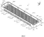
- the bottom surface of the housing is provided with a boss inserted into a positioning hole in a circuit board, and three floating contacts are provided at the frontage on the side opposite to the side with the boss in the housing.
- the distance between the center of the frontage of the housing, which is referred to as the frontage center, and the boss is an essential measurement element.
- the boss is on the side opposite to the frontage of the housing and they are partitioned via the bottom plate, the frontage and the boss cannot be directly viewed at the same time.
- the distance between the frontage center and the boss is measured with the following three step procedures.
- the width D 1 of the frontage 400 in the housing 500 is measured and the center thereof is defined as the frontage center FC.
- the distance D 2 between the outer side surfaces of the side walls 100 a and 100 b on the left side and right side is measured, the center thereof is defined as the outer shape center OC, and the difference Da between the frontage center FC and the outer shape center OC is obtained.
- the distance Db between the outer shape center OC and the boss 390 c is measured, and the sum of the distance Da and the distance Db is defined as the distance Dc between the frontage center FC and the boss 390 c.
- the present disclosure has been made in view of such a problem, and one of the objects is to provide a high-speed transmission connector which can be designed with a severe tolerance.
- a housing of a high-speed transmission connector fitted to a connector of a counterpart substrate via a frontage includes: a bottom plate forming a bottom of the frontage and being provided with at least one boss on a surface opposite to the frontage side; a pair of first side walls facing each other in a first direction with the frontage sandwiched therebetween; and a pair of second side walls facing each other in a second direction orthogonal to the first direction with the frontage sandwiched therebetween.
- the bottom plate is provided with first through holes for tolerance measurement having inner peripheral surfaces including side wall surfaces of the first side walls in the same planes and/or second through holes for tolerance measurement having inner peripheral surfaces including side wall surfaces of the second side walls in the same planes.
- a high-speed transmission connector includes: a frontage to which a connector of a counterpart substrate is fitted; a bottom plate forming a bottom of the frontage and being provided with a plurality of support holes and provided with one or a plurality of bosses on a surface opposite to the frontage side; a pair of first side walls intersecting with the bottom plate and facing each other in a first direction with the frontage sandwiched therebetween; and a pair of second side walls intersecting with the bottom plate and facing each other in a second direction orthogonal to the first direction with the frontage sandwiched therebetween.
- the bottom plate includes: a housing provided with first through holes for tolerance measurement having inner peripheral surfaces including side wall surfaces of the first side walls in the same planes and/or second through holes for tolerance measurement having inner peripheral surfaces including side wall surfaces of the second side walls in same planes; and a plurality of contacts fixed to the support holes.
- FIG. 1 is a perspective view of a high-speed transmission connector 1 including a housing 5 according to an embodiment of the present disclosure
- FIG. 2 is a perspective view of the high-speed transmission connector 1 of FIG. 1 as viewed from another angle;
- FIGS. 3A-3F are six-sided views of the high-speed transmission connector 1 of FIG. 1 and FIG. 2 ;
- FIG. 4 is a perspective view of the housing 5 of FIG. 1 ;
- FIG. 5 is a perspective view of the housing 5 of FIG. 4 as viewed from another angle;
- FIGS. 6A-6F are six-sided views of the housing 5 of FIG. 4 and FIG. 5 ;
- FIG. 7 is a diagram showing a procedure for measuring the distance between the frontage center FC and the boss 39 c in the housing 5 of FIG. 4 , FIG. 5 , and FIG. 6 ;
- FIG. 8 is a diagram showing a procedure for measuring the distance between the frontage center FC and the boss 390 c in the housing 500 of a conventional high-speed transmission connector 1 .
- the high-speed transmission connector 1 is used by soldering to a pad of an electronic substrate.
- the high-speed transmission connector 1 has a frontage 40 with a bottom.
- the frontage 40 of the high-speed transmission connector 1 is fitted with a header of the connector 1 of a communication counterpart substrate.
- the header of the connector 1 of the communication counterpart substrate is fitted to the frontage 40 of the high-speed transmission connector 1 , high-speed transmission of signals between the two substrates becomes possible.
- the fitting direction of the high-speed transmission connector 1 and the connector of the communication counterpart substrate is appropriately referred to as the Z direction
- a direction orthogonal to the Z direction is appropriately referred to as the X direction
- the direction orthogonal to the Z direction and the X direction is appropriately referred to as Y direction.
- the housing 5 has a bottom plate 30 , a pair of first side walls 10 a and 10 b intersecting with the bottom plate 30 and facing each other in the X direction with the frontage 40 sandwiched therebetween, and a pair of second side walls 20 c and 20 d intersecting with the bottom plate 30 and facing each other in the Y direction with the frontage 40 sandwiched therebetween.
- a boss 39 c is provided slightly inside the end edge on the +X side
- a boss 39 d is provided slightly inside the end edge on the ⁇ X side.
- the boss 39 c has a cylindrical shape.
- the boss 39 d has an elliptic cylindrical shape.
- protrusions 36 a - 1 and 36 a - 2 are provide at positions separated from the boss 39 c to the +Y side and the ⁇ Y side
- protrusions 36 b - 1 and 36 b - 2 are provided at positions separated from the boss 39 d to the +X side and the ⁇ X side.
- the rectangular portion of the back surface of the bottom plate 30 on the inner sides of the bosses 39 c and 39 d is slightly recessed to the +Z side as stepped portions 38 .
- a first recess portion 12 a is provided at a portion ranging from the outer side wall surface of the first side wall 10 a on the +X side to the back surface of the bottom plate 30 .
- a first recess portion 12 b is provided at a portion ranging from the outer side wall surface of the first side wall 10 b to the back surface of the bottom plate 30 .
- a first convex portion 13 b is provided on the inner side wall surface of the first side wall 10 b on the ⁇ X side facing the frontage 40 side.
- the first convex portion 13 b protrudes inward with a thickness thicker than that of the first side wall 10 b.
- the bottom plate 30 are provided with the first through holes 31 a - 1 , 31 a - 2 , 31 b - 1 , and 31 b - 2 and the second through holes 32 c - 1 , 32 c - 2 , 32 d - 1 , and 32 d - 2 each for tolerance measurement.
- the first through holes 31 a - 1 , 31 a - 2 , 31 b - 1 , and 31 b - 2 have inner peripheral surfaces including the inner side wall surface of the first side wall 10 a in the same plane.
- the second through holes 32 c - 1 , 32 c - 2 , 32 d - 1 , and 32 d - 2 have inner peripheral surfaces including the inner side wall surface of the second side wall 20 c in the same plane.
- the two first through holes 31 a - 1 and 31 a - 2 are located in the bottom plate 30 at positions along the first intersection line intersecting with the inner side wall surface of the first side wall 10 a on the +X side, and are located at positions apart from each other on the +Y side and the ⁇ Y side.
- the two first through holes 31 b - 1 and 31 b - 2 are located in the bottom plate 30 at positions along the first intersection line intersecting with the inner side wall surface of the first side wall 10 b on the ⁇ X side and being apart from each other on the +Y side and the ⁇ Y side.
- the first through holes 31 a - 1 , 31 a - 2 , 31 b - 1 , and 31 b - 2 penetrate between the front surface and the back surface of the bottom plate 30 .
- the first through holes 31 a - 1 , 31 a - 2 , 31 b - 1 , and 31 b - 2 are square-shaped.
- the inner peripheral surface on the +X side is flush with the inner side wall surface of the first side wall 10 a .
- the inner peripheral surface on the ⁇ X side is flush with the inner side wall surface of the first side wall 10 b .
- the second through holes 32 c - 1 , 32 c - 2 , 32 d - 1 , and 32 d - 2 penetrate between the front surface and the back surface of the bottom plate 30 .
- the second through holes 32 c - 1 , 32 c - 2 , 32 d - 1 , and 32 d - 2 are square-shaped.
- the inner peripheral surface on the +Y side is flush with the inner side wall surface of the second side wall 20 c .
- the inner peripheral surface on the ⁇ Y side is flush with the inner side wall surface of the second side wall 20 c.
- the high-speed transmission connector 1 of the present embodiment includes: a bottom plate 30 forming a bottom of frontage 40 and being provided with a boss 39 c on a surface opposite to the frontage 40 ; a pair of first side walls 10 a and 10 b intersecting with the bottom plate 30 and facing each other in the X direction, which is the first direction, with the frontage 40 sandwiched therebetween; and a pair of second side walls 20 c and 20 d intersecting with the bottom plate 30 and facing each other in the Y direction, which is the second direction, with the frontage 40 sandwiched therebetween.
- the bottom plate 30 are provided with first through holes 31 a - 1 , 31 a - 2 , 31 b - 1 , and 31 b - 2 for tolerance measurement in the X direction which have inner peripheral surfaces including the side wall surfaces of the first side walls 10 a and 10 b in the same planes, and second through holes 32 c - 1 , 32 c - 2 , 32 d - 1 , and 32 d - 2 for tolerance measurement in the Y direction which have inner peripheral surfaces including the side wall surfaces of the second side walls 20 c and 20 d in the same planes.
- first through holes 31 a - 1 , 31 a - 2 , 31 b - 1 , and 31 b - 2 for tolerance measurement in the X direction which have inner peripheral surfaces including the side wall surfaces of the first side walls 10 a and 10 b in the same planes
- the distance Dc between the frontage center FC and the boss 39 c in the X direction can be measured by a two-step procedure consisting of measuring the distance D 1 between the first through holes 31 a - 1 and 31 b - 1 facing each other in the X direction to define the central point thereof as the frontage center FC, and of measuring the distance Dc from the boss 39 c to the frontage center FC. Further, the distance between the frontage center FC and the boss 39 c in the Y direction can also be measured by the same two-step procedure. Therefore, it is possible to provide a high-speed transmission connector 1 which can be designed with a severe tolerance.
- the first through holes 31 a - 1 , 31 a - 2 , 31 b - 1 , and 31 b - 2 at the positions along the first intersection lines intersecting with the first side walls 10 a and 10 b of the bottom plate 30 , or only the second through holes 32 c - 1 , 32 c - 2 , 32 d - 1 , and 32 d - 2 at positions along the second intersection lines intersecting with the second side walls 20 c and 20 d in the bottom plates 30 .
- one through hole may be provided for each of the intersection lines on both sides sandwiching the frontage 40 , which is common to the tolerance measurement in the X direction and the tolerance measurement in the Y direction, without separately providing the first through holes 31 a - 1 , 31 a - 2 , 31 b - 1 , and 31 b - 2 for tolerance measurement in the X direction and the second through holes 32 c - 1 , 32 c - 2 , 32 d - 1 , and 32 d - 2 for tolerance measurement in the Y direction.
- the common through holes may be provided at intersection portions where the first and second intersection lines intersecting with each other, the first intersection line intersecting with the side wall surfaces of the first side walls 10 a and 10 b , and the second intersection line intersecting with the side wall surfaces of the second side walls 20 c and 20 d . It is more preferable to provide one common through hole at each of the two corner portions of the bottom plate 30 facing each other in the diagonal direction with the frontage 40 sandwiched therebetween.
- the inner peripheral surface on the +X side may be flush with the side wall surface of the first side wall 10 a (or the first side wall 10 a ), and among the four inner peripheral surfaces, and the inner peripheral surface on the +Y side (or the ⁇ Y side) may be flush with the side wall surface of the second side wall 20 c (or the second side wall 20 d ).
Landscapes
- Connector Housings Or Holding Contact Members (AREA)
- Details Of Connecting Devices For Male And Female Coupling (AREA)
Abstract
Description
Claims (6)
Applications Claiming Priority (2)
| Application Number | Priority Date | Filing Date | Title |
|---|---|---|---|
| CN202010092843.4 | 2020-02-14 | ||
| CN202010092843.4A CN113270756B (en) | 2020-02-14 | 2020-02-14 | Housing of high-speed transmission connector and high-speed transmission connector |
Publications (2)
| Publication Number | Publication Date |
|---|---|
| US20210257771A1 US20210257771A1 (en) | 2021-08-19 |
| US11450983B2 true US11450983B2 (en) | 2022-09-20 |
Family
ID=74586905
Family Applications (1)
| Application Number | Title | Priority Date | Filing Date |
|---|---|---|---|
| US17/175,165 Active US11450983B2 (en) | 2020-02-14 | 2021-02-12 | Housing of high-speed transmission connector and high-speed transmission connector |
Country Status (3)
| Country | Link |
|---|---|
| US (1) | US11450983B2 (en) |
| EP (1) | EP3866271A1 (en) |
| CN (1) | CN113270756B (en) |
Families Citing this family (2)
| Publication number | Priority date | Publication date | Assignee | Title |
|---|---|---|---|---|
| USD978804S1 (en) | 2019-12-12 | 2023-02-21 | Yamaichi Electronics Co., Ltd. | Mezzanine connector housing |
| JP1664604S (en) * | 2019-12-12 | 2020-07-27 |
Citations (17)
| Publication number | Priority date | Publication date | Assignee | Title |
|---|---|---|---|---|
| US6179632B1 (en) | 1999-05-06 | 2001-01-30 | Hon Hai Precision Ind. Co., Ltd. | Electrical connector |
| US20090239422A1 (en) | 2008-03-21 | 2009-09-24 | Takeki Fukazawa | Electrical connector |
| US20100330844A1 (en) * | 2007-09-28 | 2010-12-30 | Toshiyasu Ito | High density connector for high speed transmission |
| US20120115366A1 (en) * | 2010-11-04 | 2012-05-10 | Yamaichi Electronics Co., Ltd. | Socket for a semiconductor device |
| US8632263B2 (en) * | 2008-04-14 | 2014-01-21 | Furukawa Electric Co., Ltd. | Optical module mounting unit and optical module |
| US20150270658A1 (en) * | 2014-03-18 | 2015-09-24 | Japan Aviation Electronics Industry, Limited | Connector |
| US20170125946A1 (en) * | 2012-07-11 | 2017-05-04 | Fci Americas Technology Llc | Electrical connector with reduced stack height |
| US20170250484A1 (en) * | 2016-02-25 | 2017-08-31 | Yamaichi Electronics Co., Ltd. | Contact terminal and ic socket including the same |
| US20180198222A1 (en) | 2017-01-11 | 2018-07-12 | J.S.T. Mfg. Co., Ltd. | Board-to-board connector for absorbing misalignment |
| US10164361B2 (en) * | 2015-01-15 | 2018-12-25 | Fci Usa Llc | Separator for electrical assembly |
| US10405448B2 (en) * | 2017-04-28 | 2019-09-03 | Fci Usa Llc | High frequency BGA connector |
| US20210044060A1 (en) * | 2019-08-07 | 2021-02-11 | Foxconn (Kunshan) Computer Connector Co., Ltd. | Electrical connector assembly |
| US20210111504A1 (en) * | 2019-10-10 | 2021-04-15 | Hirose Electric Co., Ltd. | Electrical connector and method for manufacturing same |
| US20210126385A1 (en) * | 2019-10-23 | 2021-04-29 | Starconn Electronic (Su Zhou) Co., Ltd | Electrical connector |
| US20210175658A1 (en) * | 2019-12-10 | 2021-06-10 | Yamaichi Electronics Co., Ltd. | Inspection Socket |
| US20210184383A1 (en) * | 2019-12-11 | 2021-06-17 | Yamaichi Electronics Co., Ltd. | Connector for high-speed transmission and method for fixing solder to fork portion of connector for high-speed transmission |
| US20210378121A1 (en) * | 2020-06-02 | 2021-12-02 | Yamaichi Electronics Co., Ltd. | Connector, ic package, and method of mounting contacts to housing of connector |
Family Cites Families (14)
| Publication number | Priority date | Publication date | Assignee | Title |
|---|---|---|---|---|
| CN1068114C (en) * | 1995-08-08 | 2001-07-04 | 重庆大学 | Measuring device and method for hole-shaft mixed parts |
| US5820393A (en) * | 1996-12-30 | 1998-10-13 | Molex Incorporation | Board mounted electrical connector with multi-function board lock |
| JP4615956B2 (en) * | 2004-10-14 | 2011-01-19 | スリオジャパン株式会社 | connector |
| DE102006027748A1 (en) * | 2006-06-16 | 2007-12-20 | Robert Bosch Gmbh | Printed circuit board for airbag control device of motor vehicle, has protection section that has passage openings for pressing pins, where passage openings of section lie over passage openings of pressing sockets |
| JP4301414B2 (en) * | 2006-12-06 | 2009-07-22 | ヒロセ電機株式会社 | Circuit board electrical connector |
| JP4607926B2 (en) * | 2007-08-27 | 2011-01-05 | 力成科技股▲分▼有限公司 | BGA package jig |
| CN201667447U (en) * | 2009-12-15 | 2010-12-08 | 富士康(昆山)电脑接插件有限公司 | Electric connector |
| JP5534350B2 (en) * | 2011-02-16 | 2014-06-25 | 住友電装株式会社 | Connector device |
| EP2772991A4 (en) * | 2011-10-28 | 2015-10-28 | Sumitomo Wiring Systems | Connector |
| JP5912632B2 (en) * | 2012-02-16 | 2016-04-27 | 日本圧着端子製造株式会社 | connector |
| JP6472407B2 (en) * | 2015-09-07 | 2019-02-20 | 矢崎総業株式会社 | connector |
| JP7137939B2 (en) * | 2017-05-19 | 2022-09-15 | モレックス エルエルシー | Connectors and connector assemblies |
| JP6761375B2 (en) * | 2017-05-29 | 2020-09-23 | 京セラ株式会社 | Electrical connector |
| CN211208765U (en) * | 2020-02-14 | 2020-08-07 | 山一电机株式会社 | High-speed transmission connector housing and high-speed transmission connector |
-
2020
- 2020-02-14 CN CN202010092843.4A patent/CN113270756B/en active Active
-
2021
- 2021-02-10 EP EP21156295.4A patent/EP3866271A1/en active Pending
- 2021-02-12 US US17/175,165 patent/US11450983B2/en active Active
Patent Citations (18)
| Publication number | Priority date | Publication date | Assignee | Title |
|---|---|---|---|---|
| US6179632B1 (en) | 1999-05-06 | 2001-01-30 | Hon Hai Precision Ind. Co., Ltd. | Electrical connector |
| US20100330844A1 (en) * | 2007-09-28 | 2010-12-30 | Toshiyasu Ito | High density connector for high speed transmission |
| US20090239422A1 (en) | 2008-03-21 | 2009-09-24 | Takeki Fukazawa | Electrical connector |
| US8632263B2 (en) * | 2008-04-14 | 2014-01-21 | Furukawa Electric Co., Ltd. | Optical module mounting unit and optical module |
| US20120115366A1 (en) * | 2010-11-04 | 2012-05-10 | Yamaichi Electronics Co., Ltd. | Socket for a semiconductor device |
| US20170125946A1 (en) * | 2012-07-11 | 2017-05-04 | Fci Americas Technology Llc | Electrical connector with reduced stack height |
| US20150270658A1 (en) * | 2014-03-18 | 2015-09-24 | Japan Aviation Electronics Industry, Limited | Connector |
| US10164361B2 (en) * | 2015-01-15 | 2018-12-25 | Fci Usa Llc | Separator for electrical assembly |
| US20170250484A1 (en) * | 2016-02-25 | 2017-08-31 | Yamaichi Electronics Co., Ltd. | Contact terminal and ic socket including the same |
| US20180198222A1 (en) | 2017-01-11 | 2018-07-12 | J.S.T. Mfg. Co., Ltd. | Board-to-board connector for absorbing misalignment |
| JP2018113146A (en) | 2017-01-11 | 2018-07-19 | 日本圧着端子製造株式会社 | Board to Board Connector |
| US10405448B2 (en) * | 2017-04-28 | 2019-09-03 | Fci Usa Llc | High frequency BGA connector |
| US20210044060A1 (en) * | 2019-08-07 | 2021-02-11 | Foxconn (Kunshan) Computer Connector Co., Ltd. | Electrical connector assembly |
| US20210111504A1 (en) * | 2019-10-10 | 2021-04-15 | Hirose Electric Co., Ltd. | Electrical connector and method for manufacturing same |
| US20210126385A1 (en) * | 2019-10-23 | 2021-04-29 | Starconn Electronic (Su Zhou) Co., Ltd | Electrical connector |
| US20210175658A1 (en) * | 2019-12-10 | 2021-06-10 | Yamaichi Electronics Co., Ltd. | Inspection Socket |
| US20210184383A1 (en) * | 2019-12-11 | 2021-06-17 | Yamaichi Electronics Co., Ltd. | Connector for high-speed transmission and method for fixing solder to fork portion of connector for high-speed transmission |
| US20210378121A1 (en) * | 2020-06-02 | 2021-12-02 | Yamaichi Electronics Co., Ltd. | Connector, ic package, and method of mounting contacts to housing of connector |
Non-Patent Citations (1)
| Title |
|---|
| European Search Report dated Jun. 24, 2021 in corresponding EP application No. 21156295.4. |
Also Published As
| Publication number | Publication date |
|---|---|
| US20210257771A1 (en) | 2021-08-19 |
| EP3866271A1 (en) | 2021-08-18 |
| CN113270756A (en) | 2021-08-17 |
| CN113270756B (en) | 2023-05-23 |
Similar Documents
| Publication | Publication Date | Title |
|---|---|---|
| US11444398B2 (en) | High density electrical connector | |
| CN108281852B (en) | Connector with Shielding Shield | |
| US10763604B2 (en) | Plug, receptacle, and connector | |
| TW202143574A (en) | Connector assembly and connector | |
| KR20170136423A (en) | Connector and connector system | |
| CN106410460A (en) | Electrical connector device for substrate connection | |
| US10243288B2 (en) | Female-type electrical connector, male-type electrical connector, and electrical connector assembly utilizing same | |
| JP2017033655A (en) | Electrical connector for board connection | |
| US20230187879A1 (en) | Electrical connector | |
| US11450983B2 (en) | Housing of high-speed transmission connector and high-speed transmission connector | |
| CN104466538A (en) | Electrical connector | |
| EP4020721B1 (en) | Connector assembly | |
| CN105870675B (en) | Construction for substrate connector device | |
| US9147976B2 (en) | Connector and signal line structure | |
| US8246389B2 (en) | Electrical connector having improved crosstalk compensating paddle board | |
| US4589720A (en) | Planar electronic filter element and a connector embodying such a filter | |
| JP2023016919A (en) | connector | |
| CN211208765U (en) | High-speed transmission connector housing and high-speed transmission connector | |
| TWI871409B (en) | Connectors and connector units | |
| EP0132327A2 (en) | A planar electronic filter element and a connector embodying such a filter | |
| CN209981646U (en) | A connector and connecting assembly | |
| US20240380156A1 (en) | Electrical connector assembly | |
| JP2010123468A (en) | Electric connector | |
| JPH07161415A (en) | Electric connector and electric contact using this connector | |
| US20240380154A1 (en) | Electrical connector for circuit boards |
Legal Events
| Date | Code | Title | Description |
|---|---|---|---|
| AS | Assignment |
Owner name: YAMAICHI ELECTRONICS CO., LTD., JAPAN Free format text: ASSIGNMENT OF ASSIGNORS INTEREST;ASSIGNOR:SHIMOYAMA, TAKAHIRO;REEL/FRAME:055248/0705 Effective date: 20201215 |
|
| FEPP | Fee payment procedure |
Free format text: ENTITY STATUS SET TO UNDISCOUNTED (ORIGINAL EVENT CODE: BIG.); ENTITY STATUS OF PATENT OWNER: LARGE ENTITY |
|
| STPP | Information on status: patent application and granting procedure in general |
Free format text: APPLICATION DISPATCHED FROM PREEXAM, NOT YET DOCKETED |
|
| STPP | Information on status: patent application and granting procedure in general |
Free format text: DOCKETED NEW CASE - READY FOR EXAMINATION |
|
| STPP | Information on status: patent application and granting procedure in general |
Free format text: NON FINAL ACTION MAILED |
|
| STPP | Information on status: patent application and granting procedure in general |
Free format text: RESPONSE TO NON-FINAL OFFICE ACTION ENTERED AND FORWARDED TO EXAMINER |
|
| STPP | Information on status: patent application and granting procedure in general |
Free format text: NOTICE OF ALLOWANCE MAILED -- APPLICATION RECEIVED IN OFFICE OF PUBLICATIONS |
|
| STPP | Information on status: patent application and granting procedure in general |
Free format text: PUBLICATIONS -- ISSUE FEE PAYMENT VERIFIED |
|
| STCF | Information on status: patent grant |
Free format text: PATENTED CASE |
|
| MAFP | Maintenance fee payment |
Free format text: PAYMENT OF MAINTENANCE FEE, 4TH YEAR, LARGE ENTITY (ORIGINAL EVENT CODE: M1551); ENTITY STATUS OF PATENT OWNER: LARGE ENTITY Year of fee payment: 4 |