US11441925B2 - Method for defining a measurement range of an inductive position sensor - Google Patents
Method for defining a measurement range of an inductive position sensor Download PDFInfo
- Publication number
- US11441925B2 US11441925B2 US16/643,624 US201816643624A US11441925B2 US 11441925 B2 US11441925 B2 US 11441925B2 US 201816643624 A US201816643624 A US 201816643624A US 11441925 B2 US11441925 B2 US 11441925B2
- Authority
- US
- United States
- Prior art keywords
- signal
- winding
- sine
- cosine
- sine signal
- Prior art date
- Legal status (The legal status is an assumption and is not a legal conclusion. Google has not performed a legal analysis and makes no representation as to the accuracy of the status listed.)
- Active, expires
Links
Images


Classifications
-
- G—PHYSICS
- G01—MEASURING; TESTING
- G01D—MEASURING NOT SPECIALLY ADAPTED FOR A SPECIFIC VARIABLE; ARRANGEMENTS FOR MEASURING TWO OR MORE VARIABLES NOT COVERED IN A SINGLE OTHER SUBCLASS; TARIFF METERING APPARATUS; MEASURING OR TESTING NOT OTHERWISE PROVIDED FOR
- G01D5/00—Mechanical means for transferring the output of a sensing member; Means for converting the output of a sensing member to another variable where the form or nature of the sensing member does not constrain the means for converting; Transducers not specially adapted for a specific variable
- G01D5/12—Mechanical means for transferring the output of a sensing member; Means for converting the output of a sensing member to another variable where the form or nature of the sensing member does not constrain the means for converting; Transducers not specially adapted for a specific variable using electric or magnetic means
- G01D5/14—Mechanical means for transferring the output of a sensing member; Means for converting the output of a sensing member to another variable where the form or nature of the sensing member does not constrain the means for converting; Transducers not specially adapted for a specific variable using electric or magnetic means influencing the magnitude of a current or voltage
- G01D5/20—Mechanical means for transferring the output of a sensing member; Means for converting the output of a sensing member to another variable where the form or nature of the sensing member does not constrain the means for converting; Transducers not specially adapted for a specific variable using electric or magnetic means influencing the magnitude of a current or voltage by varying inductance, e.g. by a movable armature
- G01D5/22—Mechanical means for transferring the output of a sensing member; Means for converting the output of a sensing member to another variable where the form or nature of the sensing member does not constrain the means for converting; Transducers not specially adapted for a specific variable using electric or magnetic means influencing the magnitude of a current or voltage by varying inductance, e.g. by a movable armature differentially influencing two coils
- G01D5/225—Mechanical means for transferring the output of a sensing member; Means for converting the output of a sensing member to another variable where the form or nature of the sensing member does not constrain the means for converting; Transducers not specially adapted for a specific variable using electric or magnetic means influencing the magnitude of a current or voltage by varying inductance, e.g. by a movable armature differentially influencing two coils by influencing the mutual induction between the two coils
-
- G—PHYSICS
- G01—MEASURING; TESTING
- G01B—MEASURING LENGTH, THICKNESS OR SIMILAR LINEAR DIMENSIONS; MEASURING ANGLES; MEASURING AREAS; MEASURING IRREGULARITIES OF SURFACES OR CONTOURS
- G01B7/00—Measuring arrangements characterised by the use of electric or magnetic techniques
- G01B7/30—Measuring arrangements characterised by the use of electric or magnetic techniques for measuring angles or tapers; for testing the alignment of axes
-
- G—PHYSICS
- G01—MEASURING; TESTING
- G01D—MEASURING NOT SPECIALLY ADAPTED FOR A SPECIFIC VARIABLE; ARRANGEMENTS FOR MEASURING TWO OR MORE VARIABLES NOT COVERED IN A SINGLE OTHER SUBCLASS; TARIFF METERING APPARATUS; MEASURING OR TESTING NOT OTHERWISE PROVIDED FOR
- G01D5/00—Mechanical means for transferring the output of a sensing member; Means for converting the output of a sensing member to another variable where the form or nature of the sensing member does not constrain the means for converting; Transducers not specially adapted for a specific variable
- G01D5/12—Mechanical means for transferring the output of a sensing member; Means for converting the output of a sensing member to another variable where the form or nature of the sensing member does not constrain the means for converting; Transducers not specially adapted for a specific variable using electric or magnetic means
- G01D5/14—Mechanical means for transferring the output of a sensing member; Means for converting the output of a sensing member to another variable where the form or nature of the sensing member does not constrain the means for converting; Transducers not specially adapted for a specific variable using electric or magnetic means influencing the magnitude of a current or voltage
- G01D5/20—Mechanical means for transferring the output of a sensing member; Means for converting the output of a sensing member to another variable where the form or nature of the sensing member does not constrain the means for converting; Transducers not specially adapted for a specific variable using electric or magnetic means influencing the magnitude of a current or voltage by varying inductance, e.g. by a movable armature
- G01D5/204—Mechanical means for transferring the output of a sensing member; Means for converting the output of a sensing member to another variable where the form or nature of the sensing member does not constrain the means for converting; Transducers not specially adapted for a specific variable using electric or magnetic means influencing the magnitude of a current or voltage by varying inductance, e.g. by a movable armature by influencing the mutual induction between two or more coils
- G01D5/2053—Mechanical means for transferring the output of a sensing member; Means for converting the output of a sensing member to another variable where the form or nature of the sensing member does not constrain the means for converting; Transducers not specially adapted for a specific variable using electric or magnetic means influencing the magnitude of a current or voltage by varying inductance, e.g. by a movable armature by influencing the mutual induction between two or more coils by a movable non-ferromagnetic conductive element
-
- G—PHYSICS
- G01—MEASURING; TESTING
- G01D—MEASURING NOT SPECIALLY ADAPTED FOR A SPECIFIC VARIABLE; ARRANGEMENTS FOR MEASURING TWO OR MORE VARIABLES NOT COVERED IN A SINGLE OTHER SUBCLASS; TARIFF METERING APPARATUS; MEASURING OR TESTING NOT OTHERWISE PROVIDED FOR
- G01D5/00—Mechanical means for transferring the output of a sensing member; Means for converting the output of a sensing member to another variable where the form or nature of the sensing member does not constrain the means for converting; Transducers not specially adapted for a specific variable
- G01D5/12—Mechanical means for transferring the output of a sensing member; Means for converting the output of a sensing member to another variable where the form or nature of the sensing member does not constrain the means for converting; Transducers not specially adapted for a specific variable using electric or magnetic means
- G01D5/14—Mechanical means for transferring the output of a sensing member; Means for converting the output of a sensing member to another variable where the form or nature of the sensing member does not constrain the means for converting; Transducers not specially adapted for a specific variable using electric or magnetic means influencing the magnitude of a current or voltage
- G01D5/20—Mechanical means for transferring the output of a sensing member; Means for converting the output of a sensing member to another variable where the form or nature of the sensing member does not constrain the means for converting; Transducers not specially adapted for a specific variable using electric or magnetic means influencing the magnitude of a current or voltage by varying inductance, e.g. by a movable armature
- G01D5/22—Mechanical means for transferring the output of a sensing member; Means for converting the output of a sensing member to another variable where the form or nature of the sensing member does not constrain the means for converting; Transducers not specially adapted for a specific variable using electric or magnetic means influencing the magnitude of a current or voltage by varying inductance, e.g. by a movable armature differentially influencing two coils
- G01D5/225—Mechanical means for transferring the output of a sensing member; Means for converting the output of a sensing member to another variable where the form or nature of the sensing member does not constrain the means for converting; Transducers not specially adapted for a specific variable using electric or magnetic means influencing the magnitude of a current or voltage by varying inductance, e.g. by a movable armature differentially influencing two coils by influencing the mutual induction between the two coils
- G01D5/2275—Mechanical means for transferring the output of a sensing member; Means for converting the output of a sensing member to another variable where the form or nature of the sensing member does not constrain the means for converting; Transducers not specially adapted for a specific variable using electric or magnetic means influencing the magnitude of a current or voltage by varying inductance, e.g. by a movable armature differentially influencing two coils by influencing the mutual induction between the two coils by a movable non-ferromagnetic conductive element
Definitions
- the present invention relates to a method for defining a measurement range of a contactless inductive position sensor in order to obtain for the sensor a measurement window that is as large and as regular as possible.
- the inductive position sensor is suitable for detecting a movement of at least one target as it comprises at least one first receiver winding that generates a sine signal during the detection of said at least one target and at least one second receiver winding that generates a cosine signal during the detection of said at least one target.
- each receiver winding comprises at least two winding loops.
- the parameters of the sine and cosine signals in particular the amplitude and the period of the sinusoidal signals, respectively depend on dimension and positioning parameters of said at least two winding loops.
- an inductive position sensor defines a spatial measurement window, for example an annular or linear segment, that is passed through periodically by one or more than one moving targets, which most frequently are in rotation.
- an inductive position sensor comprises, in a known manner, a printed-circuit carrier 22 , which most frequently takes the form of a board.
- the printed-circuit carrier 22 is configured accordingly.
- the printed-circuit carrier 22 is shown in a linear fashion, i.e. flat.
- This printed-circuit carrier 22 comprises a primary winding 24 and two secondary windings 25 Sa, 26 Ca that are coupled to the primary winding 24 .
- the windings 24 , 25 Sa, 26 Ca may be connected to an electronic module for managing said windings 24 , 25 Sa, 26 Ca, this electronic module not being illustrated in FIG. 1 .
- a primary winding allows a magnetic field to be generated during the flow of current through said primary winding. The magnetic field thus created is perceived by the secondary windings, and induces a voltage in said secondary windings.
- the target modifies the magnetic coupling between the primary winding 24 and the two secondary windings 25 Sa, 26 Ca.
- the primary winding 24 is referred to as the emitter winding whereas the secondary windings 25 Sa, 26 Ca are referred to as receiver windings.
- the receiver windings 25 Sa, 26 Ca placed in proximity to said target see an amount of flux of the magnetic field that is lower than if the target were absent. If, for example, a receiver winding 25 Sa, 26 Ca consists of two loops of opposite orientation and if the target moves above one then the other of these loops, this receiver winding 25 Sa, 26 Ca sees, with respect to a zero average value, a relative increase then a relative decrease in the amount of flux of the magnetic field that passes through it.
- the receiver windings 25 Sa, 26 Ca are of different natures.
- FIG. 1 which shows a close-up view of the measurement window F
- the sine/cosine signals are temporally correlated, by a computation of the arctangent, in order to precisely determine the position of the target.
- target forming sine and cosine signals what is meant is not only a single target that interacts with receiver windings but also two target portions or at least two consecutive targets that are offset during the movement and that simultaneously interact with receiver windings.
- the sine receiver winding 25 Sa comprises a whole loop MS ⁇ that is negatively oriented and a whole loop MS+ that is positively oriented whereas the cosine receiver winding 26 Ca comprises a first positive half-loop 1 ⁇ 2 MC+, a negative whole loop MC ⁇ and a second positive half-loop 1 ⁇ 2 MC+.
- Such an offset allows a cosine winding to be formed by taking advantage, to form a cosine signal, of the mathematical relationship that relates a sine to a cosine. This allows sine and cosine signals similar to the prior art but devoid of defects at the limits of the measurement window to be obtained. This is in particular illustrated by the document FR-A-3 023 611, incorporated herein by reference.
- the problem behind an aspect of the present invention is, for an inductive position sensor having a measurement window for the detection of one or more moving targets, to increase the length of the measurement window and the precision of the detection of the target.
- an aspect of the present invention relates to a method for defining a measurement range, called the useful span, of an inductive position sensor during the design thereof, the sensor being suitable for detecting a movement of at least one target as it comprises at least one first receiver winding that generates a sine signal during the detection of said at least one target and at least one second receiver winding that generates a cosine signal during the detection of said at least one target, each receiver winding comprising at least two winding loops, parameters of the sine and cosine signals respectively depending on dimension and positioning parameters of said at least two winding loops, noteworthy in that the cosine signal is taken as reference signal between the two sine and cosine signals for an adjustment of at least one parameter of the sine signal depending on a corresponding parameter of the cosine signal, at least one of said dimension and positioning parameters of said at least two loops of said at least one first receiver winding being configured to generate a sine signal having said at least one parameter of the sine signal adjusted with respect to the cosine signal.
- the definition of the measurement range consists in shaping it, depending on parameters of the cosine and sine receiver windings, to make the measurement range optimal, i.e. as large as possible and such that it possesses a high linearity with little dependence of the taken measurements on the points in the measurement range at which they are taken.
- an offset between the receiver windings allows sine and cosine signals to be formed on the basis of a receiver winding of a shape that is initially defined solely for a sine signal.
- An offset of a quarter of a period i.e. of a half-loop, allows a cosine winding to be formed by taking advantage, to form a cosine signal, of the mathematical relationship that relates a sine to a cosine.
- An aspect of the present invention follows the opposite approach. It is the cosine signal that serves as model for an adjustment of the sine signal. It is however possible for it to be a corrected cosine signal that is used as model for the generation of a sine signal.
- said at least one parameter of the sine signal adjusted to the cosine signal is chosen unitarily or in combination from the following parameters: an amplitude of the sine signal, a period or wavelength of the sine signal and a deviation from a baseline of the sine signal.
- the period or wavelength of the sine signal is determined to be equal to x times the period or wavelength of the cosine signal, x being comprised between 0.79 and 0.93, the amplitude of the sine signal being equal to the amplitude of the cosine signal and the deviation from the baseline of the sine signal being determined to be coincident with the baseline of the cosine signal.
- the cosine function is the reference function. Achieving equal amplitudes and coincident baselines while taking as reference the cosine function, as provided for in an aspect of the present invention, is not equivalent to achieving equal amplitudes and coincident baselines while taking as reference the sine function, as proposed in the prior art.
- the respective periods of the two cosine and sine functions or signals may be different.
- the period or wavelength of the sine signal is determined to be equal to 0.86 times the period or wavelength of the cosine signal.
- the amplitude of the sine signal is modified by adjusting a width of said at least two loops of said at least one first receiver winding
- the period of the sine signal is modified by adjusting the length of said at least two loops of said at least one first receiver winding, a smaller width or length corresponding respectively to a decrease in the amplitude or in the period of the sine signal
- the deviation from the baseline of the sine signal of said at least one first receiver winding is obtained via a transverse translation of said at least two loops of said at least one first receiver winding that generates the sine signal with respect to said at least two loops of said at least one second receiver winding.
- said at least one first receiver winding that generates a sine signal thus modified and said at least one second receiver winding that generates a cosine signal are formed on a printed-circuit carrier.
- An aspect of the invention also relates to an inductive position sensor suitable for detecting a movement of at least one target, said sensor comprising a printed-circuit carrier that bears at least one first receiver winding suitable for generating a sine signal during the detection of said at least one target and at least one second receiver winding suitable for generating a cosine signal during the detection of said at least one target, each receiver winding comprising at least two winding loops formed on the printed-circuit carrier, dimension and positioning parameters of said at least two winding loops on the printed-circuit carrier defining respective parameters of the sine and cosine signals, the sensor comprising at least one emitter winding suitable for inducing a voltage in said receiver windings, the inductive position sensor being noteworthy in that at least one parameter of said at least two winding loops of said at least one first receiver winding is adjusted to generate the predetermined sine signal depending on the corresponding parameter of said at least two winding loops of said at least one second receiver winding adjusted to generate the cosine signal.
- a plurality of parameters of said at least two winding loops of said at least one first receiver winding are adjusted to generate the sine signal with a period or wavelength of the sine signal equal to x times the period or wavelength of the cosine signal, x being comprised between 0.79 and 0.93, the amplitude of the sine signal being equal to the amplitude of the cosine signal and the deviation from the baseline of the sine signal being determined to be coincident with the baseline of the cosine signal.
- the emitter winding is an angular emitter winding, said at least one first receiver winding and one second receiver winding being angular.
- An aspect of the invention also relates to an assembly having a fixed portion and a movable portion, at least one target being mounted on the movable portion, noteworthy in that it comprises such an inductive position sensor, the inductive position sensor being mounted on the fixed portion and suitable for detecting a movement of said at least one target during a movement of the movable portion.
- the assembly is mounted in a motor vehicle, the movable portion taking the form of a or comprising a movable axle bearing said at least one target.
- FIG. 1 is a schematic representation of an emitter winding, of a sine winding and of a cosine winding in an inductive position sensor according to the prior art
- FIG. 2 is a schematic representation of sine and cosine signals delivered by an inductive position sensor during a detection of a movable target according to the prior art, with a theoretical cosine signal, an actually obtained cosine signal, a theoretical sine signal and a sine signal corrected depending on the actually obtained cosine signal,
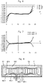
- FIGS. 3 and 4 respectively show curves of linearity and of drift as a function of the gap and of the receiver windings configured to generate a sine signal and a cosine signal, respectively, these curves being obtained for a sensor according to the prior art and these windings forming part of an inductive position sensor according to the prior art,
- FIGS. 6 and 7 respectively show curves of linearity and of drift as a function of the gap and of the receiver windings configured to generate a sine signal and a cosine signal, respectively, these curves being obtained for a sensor according to one embodiment of the present invention and these windings forming part of an inductive position sensor according to one embodiment of the present invention,
- FIGS. 5 and 8 show a measurement window of an inductive position sensor according to the prior art and according to one embodiment of the present invention, respectively, the measurement window for each of these FIGS. 5 and 8 comprising an emitter winding, sine and cosine receiver windings, the sine windings having been modified in FIG. 8 with respect to FIG. 5 depending on a cosine signal delivered by the cosine windings,
- FIG. 9 shows a schematic view in perspective of an assembly comprising a fixed portion and a movable portion with at least one target mounted on the movable portion and an inductive position sensor mounted on the fixed portion, the sensor being able to be a sensor according to an aspect of the present invention.
- an aspect of the present invention relates to a method for defining, during a design of an inductive position sensor 2 , a measurement range, called the useful span, of the sensor 2 .
- the inductive position sensor 2 is suitable for detecting a movement of at least one target 3 borne by an element the movement of which it is necessary to detect and measure. This movement may be linear or rotary or even a combination of a plurality of movements.
- the assembly 1 may be an electric motor 1 comprising a stator portion 11 and a rotor portion 12 connected to an output shaft 13 .
- a position sensor 2 is mounted fixedly with respect to the stator portion 11 of the motor 1 and is suitable for detecting the position of targets 3 that are fastened to the rotor portion 12 of the motor 1 . In a known manner, the position of the targets 3 is detected by measurements of the output voltage of the position sensor 2 .
- the inductive position sensor comprises at least one first receiver winding 25 S, 25 Sa that generates a sine signal during the detection of said at least one target 3 and at least one second receiver winding 26 C, 26 Ca that generates a cosine signal COS during the detection of said at least one target 3 .
- Each receiver winding 25 S, 25 Sa, 26 C, 26 Ca comprises at least two winding loops MS+, MS, MC+, MC ⁇ . As shown in FIGS. 5 and 8 , there may be a plurality of sine signal or cosine signal COS winding loops that overlap with an offset therebetween.
- FIG. 2 shows four signals, namely two cosine signals and two sine signals.
- the signal COS t indicates a theoretical signal giving a perfect cosine signal whereas the signal COS is the signal actually obtained by the sensor and that is kept as reference.
- FIG. 2 also shows a theoretical signal giving a perfect sine signal SIN t and a sine signal SIN cor corrected depending on the cosine signal COS actually obtained.
- Respective amplitudes of the sine and cosine signals and half-periods of the sine and cosine signals have also been referenced, Asin, Acos, 1 ⁇ 2Psin and 1 ⁇ 2Pcos, respectively, a respective period Psin or Pcos hence being extrapolable.
- reference will therefore be made to a sine signal period Psin and to a cosine signal period Pcos even though half-periods 1 ⁇ 2Psin and 1 ⁇ 2Pcos are referenced in the figures.
- cosine- and sine-signal parameters Asin, Acos, Psin, Pcos, B are dependent on dimension and positioning parameters L, I, B of said at least two winding loops MS+, MS ⁇ , MC+, MC ⁇ , respectively.
- the cosine signal COS is taken as reference signal between the two signals, i.e. the sine signal and the cosine signal COS, for an adjustment of at least one parameter Asin, Psin, B of the sine signal, which is then said to be corrected SIN cor, depending on a corresponding parameter A cos, P cos, B of the cosine signal COS.
- At least one of said dimension and positioning parameters L, I, B of said at least two loops MS+, MS ⁇ of said at least one first receiver winding 25 S is configured to generate a sine signal SIN cor having said at least one parameter Asin, Psin, B of the sine signal SIN adjusted to a corresponding parameter Acos, Pcos, B of the cosine signal COS.
- an aspect of the invention also relates to an inductive position sensor 2 suitable for detecting a movement of at least one target 3 borne by an element 1 the movement of at least one movable portion 12 of which is detected and measured.
- the inductive position sensor 2 comprises a printed-circuit carrier 22 , for example a printed-circuit board that is planar for a linear inductive sensor 2 or that is annular for an angular inductive position sensor 2 .
- the printed-circuit carrier 22 bears at least one first receiver winding 25 S suitable for generating a sine signal SIN during the detection of said at least one target 3 and at least one second receiver winding 26 C suitable for generating a cosine signal COS during the detection of said at least one target 3 .
- FIG. 8 which shows one embodiment according to an aspect of the invention
- FIG. 5 which shows a printed-circuit carrier 22 according to the prior art as regards the receiver windings 25 Sa and 26 Ca
- Each receiver winding 25 S, 26 C comprises at least two winding loops MS+, MS ⁇ , MC+, MC ⁇ formed on the printed-circuit carrier 22 , dimension and positioning parameters L, I, B of said at least two winding loops MS+, MS ⁇ , MC+, MC ⁇ on the printed-circuit carrier 22 defining respective parameters A, P, B of the sine and cosine signals SIN, COS.
- the sensor 2 comprises at least one emitter winding 51 suitable for inducing a voltage in said receiver windings 25 S, 26 C.
- At least one parameter Asin, Psin, B of said at least two winding loops MS+, MS ⁇ of said at least one first receiver winding 25 S is adjusted to generate the predetermined sine signal SIN cor depending on the corresponding parameter of said at least two winding loops MC+, MC ⁇ of said at least one second receiver winding 26 C suitable for generating the cosine signal COS.
- FIGS. 3 to 5 relate to a prior-art sensor 2 whereas FIGS. 6 to 8 relate to a sensor 2 according to one embodiment of the present invention.
- FIGS. 3 and 6 each show three linearity curves with a top linearity curve lin L, a middle linearity curve lin M and a bottom linearity curve Lin P, as a function of the length of the useful span or range of the sensor 2 measured at one end of the measurement window F mentioned above in the introductory section of the present patent application.
- These linearity curves allow a length of the useful range of the sensor, which length is in general centered symmetrically with respect to the middle of the measurement window F, to be determined.
- the acceptable linearity defining the useful range is of +/ ⁇ 1.2% and a useful span or range, in which this value is not exceeded, of 14.75 mm is deduced therefrom. Even in the useful range of the sensor, there is a large variation in the linearity, which varies by +/ ⁇ 0.9%.
- the acceptable linearity defining the useful range is of +/ ⁇ 1% and a useful span or range, in which this value is not exceeded, of 19 mm is deduced therefrom.
- the useful range of the sensor there is a small variation in the linearity, which varies by +/ ⁇ 0.3%.
- FIGS. 4 and 7 each show two curves of drift as a function of the gap with a corrected top drift curve Dentr L and a corrected bottom drift curve Dentr P, as a function of a length of the useful span or range of the sensor measured at one end of the measurement window F, the drift of a sensor necessarily being comprised between these two curves.
- These drift curves allow a length of the useful range of the sensor, which length is in general centered symmetrically with respect to the middle of the measurement window F, to be determined.
- the drift varies by +/ ⁇ 0.8% in the median zone of the curves between 5 and 20 units of distance from one end of the measurement window F whereas in FIG. 7 , for a sensor according to one embodiment of the present invention, the drift practically does not vary at all in the median zone, it being lower than 0.2% of the curves between 3 and 20 units of distance from one end of the measurement window F.
- FIGS. 5 and 8 show a first receiver winding (referenced 25 Sa and 25 S, respectively), which is configured to generate a corrected sine signal in FIG. 8 , and a second receiver winding (referenced 26 Ca and 26 C, respectively), which is configured to generate a cosine signal COS.
- the amplitude Asin and the period Psin of the sine signal SIN cor have been decreased, this corresponding to a decrease in the width and in the length of the loops of the first receiver winding 25 S.
- the one or more parameters Asin, Psin, B of the sine signal SIN cor adjusted to the cosine signal COS are chosen unitarily or in combination from the following parameters: an amplitude Asin of the sine signal SIN, a period Psin or wavelength of the sine signal SIN and a deviation from a baseline B of the sine signal.
- the period Psin or wavelength of the sine signal SIN is determined to be equal to x times the period P or wavelength of the cosine signal COS, x being comprised between 0.79 and 0.93.
- the amplitude Asin of the corrected sine signal SIN cor may be equal to the amplitude Acos of the cosine signal COS and the deviation from the baseline B of the sine signal SIN may be determined to be coincident with the baseline B of the cosine signal. It is also possible for the amplitude Asin of the sine signal SIN cor and the baseline B of the sine signal SIN cor to be adjusted differently depending on the amplitude Acos and the baseline B of the cosine signal COS.
- the period Psin or wavelength of the corrected sine signal SIN cor is determined to be equal to 0.86 times the period Pcos or wavelength of the cosine signal COS.
- the range indicated above therefore extends about this median value of 0.86 from 0.86-0.07 i.e. 0.79 to 0.86+0.07 i.e. 0.93.
- the amplitude Asin of the corrected sine signal SIN cor may be modified by adjusting a width I of said at least two loops MS+, MS ⁇ of said at least one first receiver winding 25 S, and the period Psin of the corrected sine signal SIN cor is modified by adjusting the length L of said at least two loops MS+, MS ⁇ of said at least one first receiver winding 25 S.
- a smaller width I or length L corresponds to a decrease in the amplitude Asin or in the period Psin of the corrected sine signal SIN cor, respectively. This may be done in the sense of the preferred embodiment of the present invention with wavelengths of the sine and cosine functions having a predetermined ratio varying from 0.79 to 0.93, and preferably of 0.86.
- the deviation from the baseline B of the corrected sine signal SIN cor of said at least one first receiver winding 25 S may be obtained via a transverse translation of said at least two loops MS+, MS ⁇ of said at least one first receiver winding 25 S that generate the corrected sine signal SIN cor with respect to said at least two loops MC+, MC ⁇ of said at least one second receiver winding 26 C.
- a plurality of parameters L, I, B of said at least two winding loops MS+, MS ⁇ of said at least one first receiver winding 25 S may be adjusted to generate the sine signal SIN cor with a period Psin or wavelength of the sine signal SIN cor equal to x times the period P or wavelength of the cosine signal COS, x being comprised between 0.79 and 0.93.
- the amplitude Asin of the sine signal SIN may be equal to the amplitude Acos of the cosine signal COS, the deviation from the baseline B of the sine signal SIN cor being determined to be coincident with the baseline B of the cosine signal.
- the one or more thus modified first receiver windings 25 S that generate a sine signal SIN cor and the one or more second receiver windings 26 C that generate a cosine signal COS, and advantageously a plurality of windings of each type, may be formed on a printed-circuit carrier 22 .
- the type of the first and second receiver windings 25 S, 26 C may change.
- the emitter winding which is referenced 51 in FIG. 1 , is an angular emitter winding and the one or more first receiver windings 25 S and second receiver windings 26 C are angular.
- an aspect of the invention also relates to an assembly 1 comprising a fixed portion 11 and a movable portion 12 , at least one target 3 being mounted on the movable portion 12 .
- Such an assembly 1 comprises an inductive position sensor 2 such as described above, the inductive position sensor 2 being suitable for detecting a movement of said at least one target 3 during a movement of the movable portion 12 .
- the assembly 1 forms part of a motor vehicle and comprises at least one movable and advantageously rotating axle 13 that bears said at least one target 3 .
Landscapes
- Physics & Mathematics (AREA)
- General Physics & Mathematics (AREA)
- Measurement Of Length, Angles, Or The Like Using Electric Or Magnetic Means (AREA)
- Transmission And Conversion Of Sensor Element Output (AREA)
Abstract
Description
Claims (11)
Applications Claiming Priority (3)
| Application Number | Priority Date | Filing Date | Title |
|---|---|---|---|
| FR1758264 | 2017-09-07 | ||
| FR1758264A FR3070759B1 (en) | 2017-09-07 | 2017-09-07 | METHOD FOR DEFINING A MEASUREMENT RANGE OF AN INDUCTIVE POSITION SENSOR |
| PCT/FR2018/052171 WO2019048780A1 (en) | 2017-09-07 | 2018-09-06 | Method for defining a measurement range of an inductive position sensor |
Publications (2)
| Publication Number | Publication Date |
|---|---|
| US20200400465A1 US20200400465A1 (en) | 2020-12-24 |
| US11441925B2 true US11441925B2 (en) | 2022-09-13 |
Family
ID=60081056
Family Applications (1)
| Application Number | Title | Priority Date | Filing Date |
|---|---|---|---|
| US16/643,624 Active 2039-06-07 US11441925B2 (en) | 2017-09-07 | 2018-09-06 | Method for defining a measurement range of an inductive position sensor |
Country Status (5)
| Country | Link |
|---|---|
| US (1) | US11441925B2 (en) |
| KR (1) | KR102775045B1 (en) |
| CN (1) | CN111065896B (en) |
| FR (1) | FR3070759B1 (en) |
| WO (1) | WO2019048780A1 (en) |
Families Citing this family (5)
| Publication number | Priority date | Publication date | Assignee | Title |
|---|---|---|---|---|
| US11698275B2 (en) * | 2018-05-29 | 2023-07-11 | Kyocera Avx Components (Werne) Gmbh | Rotary position sensing apparatus and method |
| DE102020209601A1 (en) * | 2020-07-30 | 2022-02-03 | SUMIDA Components & Modules GmbH | Detection device for a position sensor and detection system with such a detection device |
| US20220205814A1 (en) * | 2020-12-31 | 2022-06-30 | Mitutoyo Corporation | Sensing winding configuration for inductive position encoder |
| DE102022202500B3 (en) | 2022-01-14 | 2023-07-13 | Continental Automotive Technologies GmbH | Inductive position sensor device and braking system with an inductive position sensor device |
| WO2023134820A1 (en) | 2022-01-14 | 2023-07-20 | Continental Automotive Technologies GmbH | Inductive position sensor device and brake system having an inductive position sensor device |
Citations (12)
| Publication number | Priority date | Publication date | Assignee | Title |
|---|---|---|---|---|
| US6249234B1 (en) * | 1994-05-14 | 2001-06-19 | Absolute Sensors Limited | Position detector |
| US6483295B2 (en) | 2000-05-25 | 2002-11-19 | Hella Kg Hueck & Co. | Inductive linear position sensor including exciting and receiving coils and a movable induction coupling element |
| US20100001718A1 (en) * | 2004-12-20 | 2010-01-07 | Mark Anthony Howard | Inductive position sensor |
| US20150247746A1 (en) * | 2012-11-14 | 2015-09-03 | Baumueller Nuernberg Gmbh | Method for calibrating a rotary encoder |
| FR3023369A1 (en) | 2014-07-04 | 2016-01-08 | Continental Automotive France | ASSEMBLY COMPRISING AT LEAST ONE FIRST ENGINE, A SECOND ENGINE AND AN ANGULAR POSITION SENSOR |
| FR3023611A1 (en) | 2014-07-08 | 2016-01-15 | Continental Automotive France | ASSEMBLY COMPRISING A MOTOR VEHICLE ENGINE COMPRISING TARGETS AND AN ANGULAR POSITION SENSOR |
| FR3027103A1 (en) | 2014-10-08 | 2016-04-15 | Continental Automotive France | ANGULAR POSITION SENSOR ASSEMBLY FOR HYBRID MOTOR VEHICLE WITH COMMON SHAFT |
| US20160146637A1 (en) | 2014-11-26 | 2016-05-26 | Continental Automotive Gmbh | Inductive sensor for measuring the position of a shaft of a vehicle |
| CN106197238A (en) | 2015-05-27 | 2016-12-07 | 法国大陆汽车公司 | For using inductosyn to determine the mobile parts method along the position of axle |
| FR3043197A1 (en) | 2015-10-28 | 2017-05-05 | Continental Automotive France | DUAL TARGET DEVICE FOR DETERMINING THE POSITION OF A MOBILE AXIS OF A MOTOR VEHICLE |
| US20190195963A1 (en) * | 2017-11-01 | 2019-06-27 | Integrated Device Technology, Inc. | Sensor coil optimization |
| US20210302206A1 (en) * | 2018-09-12 | 2021-09-30 | Electricfil Automotive | Inductive position sensor with offset compensation |
Family Cites Families (3)
| Publication number | Priority date | Publication date | Assignee | Title |
|---|---|---|---|---|
| JP4047947B2 (en) * | 1996-03-16 | 2008-02-13 | 株式会社アミテック | Inductive linear position detector |
| US7449878B2 (en) * | 2005-06-27 | 2008-11-11 | Ksr Technologies Co. | Linear and rotational inductive position sensor |
| US9479134B2 (en) * | 2013-03-04 | 2016-10-25 | Texas Instruments Incorporated | Position detecting system |
-
2017
- 2017-09-07 FR FR1758264A patent/FR3070759B1/en active Active
-
2018
- 2018-09-06 WO PCT/FR2018/052171 patent/WO2019048780A1/en not_active Ceased
- 2018-09-06 KR KR1020207010002A patent/KR102775045B1/en active Active
- 2018-09-06 CN CN201880057912.9A patent/CN111065896B/en active Active
- 2018-09-06 US US16/643,624 patent/US11441925B2/en active Active
Patent Citations (15)
| Publication number | Priority date | Publication date | Assignee | Title |
|---|---|---|---|---|
| US6249234B1 (en) * | 1994-05-14 | 2001-06-19 | Absolute Sensors Limited | Position detector |
| US6483295B2 (en) | 2000-05-25 | 2002-11-19 | Hella Kg Hueck & Co. | Inductive linear position sensor including exciting and receiving coils and a movable induction coupling element |
| US20100001718A1 (en) * | 2004-12-20 | 2010-01-07 | Mark Anthony Howard | Inductive position sensor |
| US20150247746A1 (en) * | 2012-11-14 | 2015-09-03 | Baumueller Nuernberg Gmbh | Method for calibrating a rotary encoder |
| US9853526B2 (en) | 2014-07-04 | 2017-12-26 | Continental Automotive France | Assembly comprising at least a first motor, a second motor and an angular position sensor |
| FR3023369A1 (en) | 2014-07-04 | 2016-01-08 | Continental Automotive France | ASSEMBLY COMPRISING AT LEAST ONE FIRST ENGINE, A SECOND ENGINE AND AN ANGULAR POSITION SENSOR |
| FR3023611A1 (en) | 2014-07-08 | 2016-01-15 | Continental Automotive France | ASSEMBLY COMPRISING A MOTOR VEHICLE ENGINE COMPRISING TARGETS AND AN ANGULAR POSITION SENSOR |
| FR3027103A1 (en) | 2014-10-08 | 2016-04-15 | Continental Automotive France | ANGULAR POSITION SENSOR ASSEMBLY FOR HYBRID MOTOR VEHICLE WITH COMMON SHAFT |
| CN105628059A (en) | 2014-11-26 | 2016-06-01 | 法国大陆汽车公司 | Inductive sensor for measuring the position of a shaft of a vehicle |
| US20160146637A1 (en) | 2014-11-26 | 2016-05-26 | Continental Automotive Gmbh | Inductive sensor for measuring the position of a shaft of a vehicle |
| CN106197238A (en) | 2015-05-27 | 2016-12-07 | 法国大陆汽车公司 | For using inductosyn to determine the mobile parts method along the position of axle |
| US10317249B2 (en) | 2015-05-27 | 2019-06-11 | Continental Automotive France | Method for determining the position of a moving part along an axis, using an inductive sensor |
| FR3043197A1 (en) | 2015-10-28 | 2017-05-05 | Continental Automotive France | DUAL TARGET DEVICE FOR DETERMINING THE POSITION OF A MOBILE AXIS OF A MOTOR VEHICLE |
| US20190195963A1 (en) * | 2017-11-01 | 2019-06-27 | Integrated Device Technology, Inc. | Sensor coil optimization |
| US20210302206A1 (en) * | 2018-09-12 | 2021-09-30 | Electricfil Automotive | Inductive position sensor with offset compensation |
Non-Patent Citations (2)
| Title |
|---|
| Chinese Office Action with Search Report for Chinese Application No. 201880057912.9, dated Apr. 26, 2021, 6 pages. |
| International Search Report and Written Opinion for International Application No. PCT/FR2018/052171, dated Feb. 5, 2019, 9 pages. |
Also Published As
| Publication number | Publication date |
|---|---|
| KR102775045B1 (en) | 2025-03-04 |
| WO2019048780A1 (en) | 2019-03-14 |
| US20200400465A1 (en) | 2020-12-24 |
| KR20200051021A (en) | 2020-05-12 |
| FR3070759B1 (en) | 2020-09-11 |
| FR3070759A1 (en) | 2019-03-08 |
| CN111065896A (en) | 2020-04-24 |
| CN111065896B (en) | 2021-10-22 |
Similar Documents
| Publication | Publication Date | Title |
|---|---|---|
| US11441925B2 (en) | Method for defining a measurement range of an inductive position sensor | |
| US10557722B2 (en) | System for determining the position of the position indicator of a position measuring system | |
| US8098061B2 (en) | Linear inductive position sensor | |
| US8508242B2 (en) | Inductive position sensor | |
| US12098934B2 (en) | Inductive angle sensor | |
| JP4988133B2 (en) | Angle measuring apparatus and method | |
| CN112673236B (en) | Inductive position sensor with offset compensation | |
| US10330498B2 (en) | Sensor arrangement for the contactless sensing of angles of rotation on a rotating part | |
| US20090079422A1 (en) | Inductive position sensor | |
| US9915551B2 (en) | Method for dynamic linearisation of sensor signals from a magnetic strip length measuring system | |
| US10928222B2 (en) | Rotation angle sensor having a compensation element | |
| US6504361B1 (en) | Inductive measurement transducer for determining a position of a moving body | |
| US20060233123A1 (en) | Inductive position sensor with common mode corrective winding and simplified signal conditioning | |
| JP2013246051A (en) | Displacement detector | |
| US10317249B2 (en) | Method for determining the position of a moving part along an axis, using an inductive sensor | |
| US10809100B2 (en) | Electromagnetic induction type encoder | |
| JP2013501928A (en) | Current sensor array | |
| US20020030485A1 (en) | Displacement and/ or angle sensor with a meander-shaped measuring winding | |
| US11536590B2 (en) | Offset correction device and position measuring device | |
| US20200003586A1 (en) | Position detection device and position detection method | |
| US20210131829A1 (en) | Flux coupling target | |
| EP4065935B1 (en) | LINEAR MOTION SENSOR | |
| US20030141863A1 (en) | Measuring device for detecting a rotation angle in a contactless manner | |
| KR101393041B1 (en) | Inductive Sensor for Displacement or Angle for Gap Compensation | |
| CN120820176A (en) | Inductive sensor assembly for detecting motion of a moving subject |
Legal Events
| Date | Code | Title | Description |
|---|---|---|---|
| FEPP | Fee payment procedure |
Free format text: ENTITY STATUS SET TO UNDISCOUNTED (ORIGINAL EVENT CODE: BIG.); ENTITY STATUS OF PATENT OWNER: LARGE ENTITY |
|
| AS | Assignment |
Owner name: CONTINENTAL AUTOMOTIVE FRANCE, FRANCE Free format text: ASSIGNMENT OF ASSIGNORS INTEREST;ASSIGNOR:FONTANET, ALAIN;REEL/FRAME:052618/0113 Effective date: 20200226 Owner name: CONTINENTAL AUTOMOTIVE GMBH, GERMANY Free format text: ASSIGNMENT OF ASSIGNORS INTEREST;ASSIGNOR:FONTANET, ALAIN;REEL/FRAME:052618/0113 Effective date: 20200226 |
|
| STPP | Information on status: patent application and granting procedure in general |
Free format text: DOCKETED NEW CASE - READY FOR EXAMINATION |
|
| STPP | Information on status: patent application and granting procedure in general |
Free format text: NON FINAL ACTION MAILED |
|
| STPP | Information on status: patent application and granting procedure in general |
Free format text: RESPONSE TO NON-FINAL OFFICE ACTION ENTERED AND FORWARDED TO EXAMINER |
|
| STPP | Information on status: patent application and granting procedure in general |
Free format text: FINAL REJECTION MAILED |
|
| STPP | Information on status: patent application and granting procedure in general |
Free format text: NOTICE OF ALLOWANCE MAILED -- APPLICATION RECEIVED IN OFFICE OF PUBLICATIONS |
|
| STPP | Information on status: patent application and granting procedure in general |
Free format text: PUBLICATIONS -- ISSUE FEE PAYMENT RECEIVED |
|
| STCF | Information on status: patent grant |
Free format text: PATENTED CASE |
|
| AS | Assignment |
Owner name: CONTINENTAL AUTOMOTIVE GMBH, GERMANY Free format text: ASSIGNMENT OF ASSIGNORS INTEREST;ASSIGNORS:CONTINENTAL AUTOMOTIVE FRANCE S.A.S.;CONTINENTAL AUTOMOTIVE GMBH;REEL/FRAME:062492/0737 Effective date: 20221123 Owner name: VITESCO TECHNOLOGIES GMBH, GERMANY Free format text: ASSIGNMENT OF ASSIGNORS INTEREST;ASSIGNORS:CONTINENTAL AUTOMOTIVE FRANCE S.A.S.;CONTINENTAL AUTOMOTIVE GMBH;REEL/FRAME:062492/0737 Effective date: 20221123 |
|
| AS | Assignment |
Owner name: VITESCO TECHNOLOGIES GMBH, GERMANY Free format text: ASSIGNMENT OF ASSIGNORS INTEREST;ASSIGNORS:CONTINENTAL AUTOMOTIVE GMBH;VITESCO TECHNOLOGIES GMBH;REEL/FRAME:063425/0149 Effective date: 20230317 |
|
| AS | Assignment |
Owner name: SCHAEFFLER TECHNOLOGIES AG & CO. KG, GERMANY Free format text: ASSIGNMENT OF ASSIGNORS INTEREST;ASSIGNOR:VITESCO TECHNOLOGIES GMBH;REEL/FRAME:072774/0843 Effective date: 20250731 |
|
| MAFP | Maintenance fee payment |
Free format text: PAYMENT OF MAINTENANCE FEE, 4TH YEAR, LARGE ENTITY (ORIGINAL EVENT CODE: M1551); ENTITY STATUS OF PATENT OWNER: LARGE ENTITY Year of fee payment: 4 |