US11436467B2 - Foldable RFID tag having an adhesive region and an extension region - Google Patents
Foldable RFID tag having an adhesive region and an extension region Download PDFInfo
- Publication number
- US11436467B2 US11436467B2 US16/942,090 US202016942090A US11436467B2 US 11436467 B2 US11436467 B2 US 11436467B2 US 202016942090 A US202016942090 A US 202016942090A US 11436467 B2 US11436467 B2 US 11436467B2
- Authority
- US
- United States
- Prior art keywords
- tag
- asset identification
- identification tag
- region
- adhesive
- Prior art date
- Legal status (The legal status is an assumption and is not a legal conclusion. Google has not performed a legal analysis and makes no representation as to the accuracy of the status listed.)
- Active
Links
Images


Classifications
-
- G—PHYSICS
- G06—COMPUTING OR CALCULATING; COUNTING
- G06K—GRAPHICAL DATA READING; PRESENTATION OF DATA; RECORD CARRIERS; HANDLING RECORD CARRIERS
- G06K19/00—Record carriers for use with machines and with at least a part designed to carry digital markings
- G06K19/06—Record carriers for use with machines and with at least a part designed to carry digital markings characterised by the kind of the digital marking, e.g. shape, nature, code
- G06K19/067—Record carriers with conductive marks, printed circuits or semiconductor circuit elements, e.g. credit or identity cards also with resonating or responding marks without active components
- G06K19/07—Record carriers with conductive marks, printed circuits or semiconductor circuit elements, e.g. credit or identity cards also with resonating or responding marks without active components with integrated circuit chips
- G06K19/077—Constructional details, e.g. mounting of circuits in the carrier
- G06K19/07749—Constructional details, e.g. mounting of circuits in the carrier the record carrier being capable of non-contact communication, e.g. constructional details of the antenna of a non-contact smart card
- G06K19/07758—Constructional details, e.g. mounting of circuits in the carrier the record carrier being capable of non-contact communication, e.g. constructional details of the antenna of a non-contact smart card arrangements for adhering the record carrier to further objects or living beings, functioning as an identification tag
- G06K19/0776—Constructional details, e.g. mounting of circuits in the carrier the record carrier being capable of non-contact communication, e.g. constructional details of the antenna of a non-contact smart card arrangements for adhering the record carrier to further objects or living beings, functioning as an identification tag the adhering arrangement being a layer of adhesive, so that the record carrier can function as a sticker
-
- G—PHYSICS
- G06—COMPUTING OR CALCULATING; COUNTING
- G06K—GRAPHICAL DATA READING; PRESENTATION OF DATA; RECORD CARRIERS; HANDLING RECORD CARRIERS
- G06K19/00—Record carriers for use with machines and with at least a part designed to carry digital markings
- G06K19/06—Record carriers for use with machines and with at least a part designed to carry digital markings characterised by the kind of the digital marking, e.g. shape, nature, code
- G06K19/067—Record carriers with conductive marks, printed circuits or semiconductor circuit elements, e.g. credit or identity cards also with resonating or responding marks without active components
- G06K19/07—Record carriers with conductive marks, printed circuits or semiconductor circuit elements, e.g. credit or identity cards also with resonating or responding marks without active components with integrated circuit chips
- G06K19/0723—Record carriers with conductive marks, printed circuits or semiconductor circuit elements, e.g. credit or identity cards also with resonating or responding marks without active components with integrated circuit chips the record carrier comprising an arrangement for non-contact communication, e.g. wireless communication circuits on transponder cards, non-contact smart cards or RFIDs
-
- G—PHYSICS
- G06—COMPUTING OR CALCULATING; COUNTING
- G06K—GRAPHICAL DATA READING; PRESENTATION OF DATA; RECORD CARRIERS; HANDLING RECORD CARRIERS
- G06K19/00—Record carriers for use with machines and with at least a part designed to carry digital markings
- G06K19/02—Record carriers for use with machines and with at least a part designed to carry digital markings characterised by the selection of materials, e.g. to avoid wear during transport through the machine
- G06K19/025—Record carriers for use with machines and with at least a part designed to carry digital markings characterised by the selection of materials, e.g. to avoid wear during transport through the machine the material being flexible or adapted for folding, e.g. paper or paper-like materials used in luggage labels, identification tags, forms or identification documents carrying RFIDs
-
- G—PHYSICS
- G06—COMPUTING OR CALCULATING; COUNTING
- G06K—GRAPHICAL DATA READING; PRESENTATION OF DATA; RECORD CARRIERS; HANDLING RECORD CARRIERS
- G06K19/00—Record carriers for use with machines and with at least a part designed to carry digital markings
- G06K19/06—Record carriers for use with machines and with at least a part designed to carry digital markings characterised by the kind of the digital marking, e.g. shape, nature, code
- G06K19/06009—Record carriers for use with machines and with at least a part designed to carry digital markings characterised by the kind of the digital marking, e.g. shape, nature, code with optically detectable marking
- G06K19/06018—Record carriers for use with machines and with at least a part designed to carry digital markings characterised by the kind of the digital marking, e.g. shape, nature, code with optically detectable marking one-dimensional coding
- G06K19/06028—Record carriers for use with machines and with at least a part designed to carry digital markings characterised by the kind of the digital marking, e.g. shape, nature, code with optically detectable marking one-dimensional coding using bar codes
-
- G—PHYSICS
- G06—COMPUTING OR CALCULATING; COUNTING
- G06K—GRAPHICAL DATA READING; PRESENTATION OF DATA; RECORD CARRIERS; HANDLING RECORD CARRIERS
- G06K19/00—Record carriers for use with machines and with at least a part designed to carry digital markings
- G06K19/06—Record carriers for use with machines and with at least a part designed to carry digital markings characterised by the kind of the digital marking, e.g. shape, nature, code
- G06K19/08—Record carriers for use with machines and with at least a part designed to carry digital markings characterised by the kind of the digital marking, e.g. shape, nature, code using markings of different kinds or more than one marking of the same kind in the same record carrier, e.g. one marking being sensed by optical and the other by magnetic means
Definitions
- Embodiments of the present invention are generally directed to asset tracking tags, and more particularly, to asset tracking tags combining radio frequency identification (RFID) tags and visual codes.
- RFID radio frequency identification
- Tags or labels for identifying assets are generally known.
- such tags can be configured to display a visual code and/or contain an RFID transponder to uniquely identify the tag, which in turn uniquely identifies the asset marked with the tag.
- the assets to be identified can be closely clustered, leaving space at a premium, such as where the assets are arrays of servers in modern data centers.
- the asset tags must be compact, able to be placed between and/or adjacent to servers that may be separated only by 10-15 mils. At smaller sizes, however, tags may fall below a necessary level of rigidity or integrity, or they may be placed so close to the assets that interference with the tag's RFID signal results.
- tags thin enough to be placed between tightly-spaced assets, yet strong enough to retain their structural integrity.
- a way to determine whether the RFID transponder in the tag is placed sufficiently far from the asset to reduce the interference caused by proximity to the asset without making the tag itself too large.
- an embodiment of the present invention is directed to an asset identification tag having an adhesive region proximate a first end of the tag that has an adhesive disposed on at least a portion of a surface thereof, an extension region proximate a second end of the tag that has a RFID transponder disposed within the extension region, and an indicator disposed between the extension region and the adhesive region.
- an embodiment of the present invention is directed to an asset identification tag having an adhesive region proximate a first end of the tag that has an adhesive disposed on at least a portion of a surface thereof, an extension region proximate a second end of the tag having a RFID transponder disposed within the extension region, and a transition region disposed between the adhesive region and the extension region that is visually distinct from the extension region and the adhesive region.
- an embodiment of the present invention is directed to a method for making an asset identification tag, including the steps of applying a visual code to a first surface of the tag, placing an RFID transponder storing unique information on to a second surface of the tag opposite the visual code on the first surface, applying an adhesive material to the second surface of the tag at a location distinct from the RFID transponder, and verifying that at least some of the unique information stored in the RFID transponder corresponds to information presented by the visual code.
- an embodiment of the present invention is directed to a method for making a plurality of asset tags.
- the method includes applying a plurality of visual codes to a first surface of a substrate, placing a plurality of radio frequency identification (RFID) devices storing unique information on a second surface of the substrate, each of the RFID transponders being disposed opposite to a respective visual code on the first surface, the applying an adhesive material to the second surface of the substrate, separating the substrate into individual tags that each have one of the visual codes and the corresponding RFID transponder, and verifying that at least some of the unique information of each RFID transponder corresponds to the respective visual code found on the same individual tag as the RFID transponder.
- RFID radio frequency identification
- an embodiment of the present invention is directed to a method of applying an asset identification tag having an adhesive region, an extension region, and an indicator located between the adhesive region and the extension region to an asset.
- the method includes folding the tag at the indicator so that the extension region is disposed over a first portion of the adhesive region and becomes secured to an adhesive located in the first portion of the adhesive region, aligning the tag so that the extension region extends from a peripheral edge of the asset, and applying a second portion of the adhesive region to a surface of the asset.
- an embodiment of the present invention is directed to a method of applying an asset identification tag.
- the asset identification tag having an adhesive region, an extension region, and a transition region located between the adhesive region and the extension region to an asset.
- the method includes aligning the tag so that the extension region extends from a peripheral edge of the asset, confirming that the transition region is aligned with the peripheral edge of the asset, and applying at least a portion of the adhesive region to a first surface of the asset.
- FIG. 1 is a bottom plan view of an asset tag in accordance with a first exemplary embodiment of the present invention, shown in an unfolded configuration;
- FIG. 2A is a top plan view of the asset tag of FIG. 1 , shown in an unfolded configuration
- FIG. 2B is a top plan view of the asset tag of FIG. 1 , shown in a folded configuration
- FIG. 2C is a bottom plan view of the asset tag of FIG. 1 , shown in a folded configuration
- FIG. 3 is a bottom plan view of an asset tag in accordance with a second exemplary embodiment of the present invention, shown in an unfolded configuration;
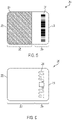
- FIG. 4 is a top plan view of an asset tag in accordance with a third exemplary embodiment of the present invention.
- FIG. 5 is a bottom plan view of the asset tag of FIG. 4 ;
- FIG. 6 is a schematic view of an interior of the asset tag of FIG. 4 ;
- FIG. 7 is a flow chart showing a method of using the asset tag of FIG. 1 ;
- FIG. 8 is a flow chart showing a method of using the asset tag of FIG. 3 ;
- FIG. 9 is a flow chart showing a method of manufacturing an asset tag
- FIG. 10 is a flow chart showing a method of manufacturing a plurality of asset tags.
- FIG. 11 is a flow chart showing a method of using the asset tag of FIG. 4 .
- one embodiment of the present invention is directed to an asset identification tag 10 preferably having an adhesive region 20 proximate a first end 22 of the asset identification tag 10 .
- An adhesive 24 such as a double coated polyester tape with an acrylic adhesive, a double coated polyester tape with a high tack acrylic adhesive, a high strength acrylic adhesive, a polyester tape with a self-sealing acrylic adhesive, or the like, is preferably disposed on at least a portion of a surface of the adhesive region 20 .
- the asset identification tag 10 also preferably has an extension region 30 proximate a second end 32 of the asset identification tag 10 opposite to the first end 22 .
- the asset identification tag 10 further preferably has a central region 70 located between the adhesive region 20 and the extension region 30 .
- An RFID transponder 34 is preferably disposed within the central region 70 , but may also be located within the extension region 30 .
- the RFID transponder 34 is preferably formed as a wet inlay, but is not so limited. While the RFID transponder 34 is shown on a surface of the central region 70 in FIG. 1 , the RFID transponder 34 may alternatively be embedded within a material of the asset identification tag 10 or otherwise encapsulated. In addition, while an RFID transponder 34 is shown in the present embodiment, other types of wireless communication devices capable of transmitting a unique product identification code to a reader may be used as well, such as a near-field communication (NFC) tag, or the like.
- NFC near-field communication
- the asset identification tag 10 also preferably has an indicator 40 disposed between the extension region 30 and the adhesive region 20 .
- the indicator 40 can be one of a perforation, printed mark, indentation, raised pattern, combinations thereof, or the like, which may take the shape of a solid line, a dashed line, a hash mark, a crosshair, a dotted line, one or more symbols, a discoloration, a registration mark, a score, or the like.
- any indication by which a user can distinguish between two regions of the asset identification tag 10 may be used in keeping with embodiments of the present invention.
- the indicator 40 may be visible to the user from one or more surfaces of the asset identification tag 10 . For example, in FIGS. 1 and 2A , the indicator 40 is seen from both the top and bottom views. This may be accomplished by perforations through the asset identification tag 10 , transparent material, matching opposed patterns formed on multiple surfaces of the asset identification tag 10 , or the like.
- the first exemplary embodiment of the asset identification tag 10 also preferably has a first visual code 60 formed on a surface of the extension region 30 and a second visual code 61 formed on a surface of the asset identification tag 10 outside of the extension region 30 .
- the second visual code 61 may be formed in the central region 70 .
- the second visual code 61 may be formed in the adhesive region.
- the visual codes 60 , 61 may be any type of visual marking that can uniquely identify an asset, such as a one-dimensional or a two-dimensional bar code, an alphanumeric code, or the like.
- the first and second visual codes 60 , 61 are machine readable.
- the RFID transponder 34 is provided on a surface of the asset identification tag 10
- one or both of the visual codes 60 , 61 may be provided on a different and/or opposing surface of the asset identification tag 10 .
- the RFID transponder 34 is shown in FIG. 1 on the bottom surface of the asset identification tag 10
- the visual codes 60 , 61 are shown in FIG. 2A on the top surface of the asset identification tag 10 .
- embodiments of the present invention do not preclude placement of the RFID transponder 34 and one or both of the visual codes 60 , 61 on the same surface.
- the first visual code 60 and the second visual code 61 are preferably identical and preferably correlate with information stored within the RFID transponder 34 to uniquely identify the asset identification tag 10 .
- the asset identification tag 10 also preferably has a marking 26 with an edge 27 disposed on at least a portion of the extension region 20 to visually distinguish at least a portion of the extension region 20 from the remainder of the asset identification tag 10 .
- the marking 26 may be formed by printing, indenting, perforation, application of an external mark (such as a sticker or the like), combinations thereof, or the like, and may take the form of an image, a symbol, a texture, a shape, a shading, a color, hashing, hatching, crosshairs, a pattern, or the like.
- the marking 26 is a printed black bar formed on a surface of the asset identification tag 10 opposite to the surface bearing the adhesive 24 .
- a length L 1 of the asset identification tag 10 in an unfolded configuration is approximately 2.5 inches and a width W 1 of the asset identification tag 10 is approximately 2 inches.
- a length L 1 ′ of the asset identification tag 10 is preferably approximately 1.5 inches.
- a length L ER of the extension region 30 is approximately 1 inch
- a length L AH of the adhesive region 20 is approximately 1 inch, which leaves approximately 0.5 inches between the adhesive and extension regions 20 , 30 for the central region 70 .
- the asset identification tag 10 is preferably configured to be folded at or proximate the indicator 40 .
- the first visual code 60 and the second visual code 61 are preferably situated so as to face opposite directions, such that one of the first visual code 60 and second visual code 61 can be seen by a user when looking at either exposed surface of the asset identification tag 10 .
- the extension region 30 preferably does not overlap with the marking 26 . Instead, the extension region 30 preferably overlaps with a portion of the central region 70 (and as a result, the RFID transponder 34 ) and/or a portion of the adhesive region 20 that does not contain the marking 26 .
- the RFID transponder 34 is preferably disposed between the first visual code 60 and the second visual code 61 . Further, in the exemplary embodiment shown in FIG. 2C , at least a portion of the extension region 30 overlaps with a portion of the adhesive 24 and is thus adhered to the adhesive region 20 . When folded in this way, a portion of the adhesive 24 and adhesive region 20 remain exposed, as shown in FIG. 2C , so that a user may apply the remaining exposed adhesive 24 to an asset (not shown) for securing the asset identification tag 10 thereto.
- the adhesive 24 preferably serves two functions: securing the folded-over extension region 30 to the remainder of the asset identification tag 10 and securing the asset identification tag 10 to the asset.
- the asset identification tag 10 may be formed of any suitable material, but is preferably a generally flexible and substantially waterproof material.
- the asset identification tag 10 is also preferably formed of a generally antistatic material.
- the asset identification tag 10 is formed of at least one of a polymeric material, a synthetic fiber, or the like having the above-described flexible, waterproof, and antistatic properties.
- the asset identification tag 10 is formed of Teslin® (TESLIN is a registered trademark of PPG Industries).
- TESLIN is a registered trademark of PPG Industries.
- the second exemplary embodiment of the asset identification tag 110 preferably has a tab 150 disposed in the adhesive region 120 .
- the tab 150 preferably has a free end 152 and an attached end 154 that is secured to the asset identification tag 110 .
- the free end 152 of the tab 150 preferably can be flexed away from the asset identification tag 110 .
- the tab 150 is also at least partially coated with an adhesive 156 .
- the attached end 154 of the tab 150 is of a unitary construction with the remainder of the asset identification tag 110 , but may be perforated along the attached end 154 .
- the tab 150 may alternatively be of a non-unitary construction with the remainder of the asset identification tag 110 , or may not be perforated along the attached end 154 .
- the attached end 154 may also be marked with a visual demarcation (not shown) such as a dashed line or the like. In use, a user may use the tab 150 to guide placement of the asset identification tag 110 on to an asset (not shown).
- the tab 150 is preferably disposed on the asset identification tag 110 such that when it is flexed away from the asset identification tag 110 , it acts as a stopper against which a surface of the asset may be placed to ensure the asset identification tag 110 is placed at the correct depth on the asset.
- a length L 2 of the second exemplary embodiment of the asset identification tag 110 is approximately 2.5 inches and a width W 2 of the second exemplary embodiment of the asset identification tag 10 is approximately 2 inches.
- a width W 2 of the second exemplary embodiment of the asset identification tag 10 is approximately 2 inches.
- the third exemplary embodiment 210 preferably includes a transition region 228 disposed between the adhesive region 220 and the extension region 230 .
- the transition region 228 is also preferably visually distinct from the extension region 230 and the adhesive region 220 .
- the transition region 228 is not limited to any form and may therefore be any visual indication suitable for distinguishing between the regions of the asset identification tag 210 , such as an image, a symbol, a texture, a shape, a shading, a color, hashing, hatching, crosshairs, a pattern, combinations thereof, or the like.
- one surface of the tag 210 corresponding to the adhesive region 220 is coated with an adhesive 224 .
- the portion of the tag 210 coated with adhesive comprises a greater area than the extension region 230 , but the invention is not so limited.
- the portion of the tag 210 coated with adhesive also preferably comprises a greater area than the transition region 228 , but again, the invention is not so limited.
- the transition region 228 of the third exemplary embodiment 210 may be a gray bar, and the adhesive region also contains a marking 226 , which may be a black bar.
- the first visual code 260 and the second visual code 261 are disposed on opposing surfaces (e.g. top and bottom) of the asset identification tag 210 , preferably on opposing surfaces of the extension region 230 .
- the RFID transponder 234 is disposed within the asset identification tag 210 in the extension region 230 .
- the asset identification tag 210 preferably has an overall length L 3 of approximately 1.75 inches and a width W 3 of approximately 2 inches. Further, the marking 226 has a length L M of approximately one-half inch, and the transition region 228 has a length L TR of approximately one-fourth of one inch.
- the method includes a step 310 of folding the asset identification tag 10 along the indicator 40 so that the extension region 30 is folded over and adjacent to the remainder of the asset identification tag 10 , including at least a portion of the adhesive region 20 , and pressing the extension region 30 to the adhesive 24 so that the extension region 30 is secured to a portion of the adhesive region 20 .
- the method further includes a step 320 of aligning the folded asset identification tag 10 with an asset (not shown) so that the extension region 30 extends beyond a peripheral edge of the asset.
- the extension region 30 may project beyond the edge of the server housing.
- the method also preferably includes a step 330 of further aligning the folded asset identification tag 10 on the asset such that the marking 26 overlaps the asset and the edge 27 of the marking 26 is aligned with the edge of the asset.
- the method then includes a step 340 of pressing the portion of the adhesive 24 and adhesive region 20 that is not covered by the extension region 30 against the asset, thereby adhering the asset identification tag 10 to the asset.
- the method may also include a preliminary step 305 of removing any temporary tape or covering (not shown) that may be present over the adhesive 24 prior to the performance of the step 310 .
- this preliminary step 305 includes peeling away only a portion of the temporary tape or covering to allow the folding of the asset identification tag 10 as described in step 310 , while retaining the temporary tape or covering over the remainder of the adhesive 24 to preserve the integrity of the adhesive 24 until the user is ready to perform step 320 .
- the asset identification tag 10 can be pre-folded and adhered to itself before being shipped to the location of the asset, which may save in the time needed to install the asset identification tag 10 in the field and the cost for skilled laborers to do so.
- the first embodiment of the asset identification tag 10 presents several advantages over the prior art.
- the asset identification tag 10 is oriented such that the RFID transponder 34 extends away from the asset by a sufficient distance so that the asset does not cause interference with the signal from the RFID antenna 34 .
- This allows the asset identification tag 10 to be placed on an asset of nearly any material, even if that material could interfere with electromagnetic radiation, such as a metal. Testing has demonstrated that reducing the distance by which the antenna 34 extends from the asset by as little as one-eighth of one inch can reduce the range of the RFID signal by as much as 50 percent.
- the first embodiment of the asset identification tag 10 contains a marking 26 to guide the user in correctly applying the asset identification tag 10 so that the antenna 34 extends outwardly from the asset by an appropriate distance.
- the folding step 310 allows the first embodiment of the asset identification tag 10 to be constructed of thinner materials.
- the first embodiment 10 may be constructed of a substrate as thin as 10-13 mils.
- the RFID transponder 34 is then protected on both sides by the 10-13 mil substrate (for a total of about 25 mils), adding additional rigidity and protection to the RFID transponder 34 without increasing the thickness of the portion of the adhesive region 20 that adheres to the asset, which can remain only 10-13 mils thick. This allows the asset identification tag 10 to gain additional rigidity surrounding the RFID transponder 34 while being capable of insertion between exceptionally closely arranged assets.
- the method of using the second exemplary embodiment 110 may include the preliminary step 405 of removing any temporary tape or covering (not shown) that may be present over the adhesive 124 prior to the performance of any other steps, as described above with respect to FIG. 7 .
- the method shown in FIG. 8 also includes a step 410 of folding the asset identification tag 110 at the indicator 140 so that the extension region 130 is folded over and adjacent to the remainder of the asset identification tag 110 , including at least a portion of the adhesive region 120 , and pressing the extension region 130 to the adhesive 124 so that the extension region 130 is secured to a portion of the adhesive region 120 .
- the method also includes a step 420 of bending the free end 152 of the tab 150 away from the asset identification tag 110 .
- the method further includes a step 430 of aligning the folded asset identification tag 110 with an asset (not shown) so that the extension region 130 extends beyond the periphery of the asset and the tab 150 abuts a face of the asset.
- the method also includes a step 440 of pressing the portion of the adhesive 124 and adhesive region 120 that is not covered by the extension region 130 against the asset, thereby adhering the asset identification tag 110 to the asset.
- the method preferably includes a step 510 of applying a visual code to a first surface of a tag, such as the asset identification tags 10 , 110 , 210 disclosed herein.
- the method also preferably includes a step 520 of placing an RFID (or other type of wireless communication) transponder to a second surface of the asset identification tag, preferably opposite the visual code.
- the RFID transponder contains at least information that uniquely identifies the RFID transponder.
- the RFID transponder may have, be connected to, or be associated with a memory, which stores the unique information.
- the memory may be a tag identifier (TID) memory, an electronic product code (EPC) memory, or any other memory suitable for storing the unique information.
- the method may also include the step 525 of programming the memory with the unique information.
- the method further preferably includes a step 530 of applying an adhesive material to at least a portion of the second surface of the asset identification tag, preferably in an adhesive region that does not overlap with the RFID transponder.
- the method also preferably includes a step 535 of applying an indicator to the asset identification tag between an extension region where the RFID transponder is disposed and the adhesive region.
- the method also preferably includes a step 540 of, after the conclusion of steps 510 and 520 , verifying that at least a portion of the unique information of the RFID transponder corresponds to the visual code. In use, this allows a user to identify an asset both by using the visual code and by using the RFID transponder.
- the method also preferably includes the step 550 of applying a substantially transparent lamination layer to the first surface of the asset identification tag. The method further preferably includes the step 560 of confirming that the indicator does not overlap the RFID transponder.
- the method preferably includes a step 610 of applying a plurality of visual codes to a first surface of a substrate.
- the method also preferably includes a step 620 of placing a plurality of RFID transponders on a second surface of the substrate, with each RFID transponder being preferably located opposite to a respective visual code on the first surface.
- the RFID transponders preferably each store at least information that uniquely identifies the respective RFID transponder.
- Each RFID transponder may have or may be associated with a memory, which stores the unique information.
- the method further preferably includes a step 630 of applying an adhesive material to a second surface of the substrate, preferably in adhesive regions that do not overlap with the respective RFID transponders.
- the method also preferably includes a step 635 of applying a plurality of indicators to the first surface of the substrate, preferably between each RFID transponder and a corresponding respective adhesive region.
- the method further preferably includes a step 640 of separating the substrate into individual tags, each having its own visual code and RFID transponder.
- the method also preferably includes a step 650 of verifying that at least a portion of the unique information of each RFID transponder corresponds to the respective visual code found opposite the corresponding RFID transponder.
- the method also preferably includes the step 660 of applying a substantially transparent lamination layer to the first surface of the substrate, if applied before step 640 , or to the first surface of each tag, if applied after step 640 .
- the method further preferably includes a step 670 of applying a visual code that identifies the sheet to either surface of the substrate, and a further step 680 of confirming that no visual code has been duplicated in the manufacturing process.
- the method of using the third exemplary embodiment 210 may include the preliminary step 705 of removing any temporary tape or covering (not shown) that may be present over an adhesive 224 prior to the performance of any other steps, as described above with respect to FIG. 7 .
- the method shown in FIG. 11 also includes a step 710 of aligning the tag 210 so that the extension region 230 extends from a peripheral edge of the asset (not shown).
- the method further includes a step 720 of confirming that a transition region 228 of the tag 210 is aligned with or overlaps a peripheral edge of the asset (not shown).
- the method also includes a step 730 of applying at least a portion of an adhesive region 220 of the tag 210 to a first surface of the asset (not shown).
Landscapes
- Engineering & Computer Science (AREA)
- Physics & Mathematics (AREA)
- General Physics & Mathematics (AREA)
- Theoretical Computer Science (AREA)
- Computer Hardware Design (AREA)
- Microelectronics & Electronic Packaging (AREA)
- Computer Networks & Wireless Communication (AREA)
- Burglar Alarm Systems (AREA)
Abstract
Description
Claims (20)
Priority Applications (1)
| Application Number | Priority Date | Filing Date | Title |
|---|---|---|---|
| US16/942,090 US11436467B2 (en) | 2019-08-07 | 2020-07-29 | Foldable RFID tag having an adhesive region and an extension region |
Applications Claiming Priority (2)
| Application Number | Priority Date | Filing Date | Title |
|---|---|---|---|
| US201962883962P | 2019-08-07 | 2019-08-07 | |
| US16/942,090 US11436467B2 (en) | 2019-08-07 | 2020-07-29 | Foldable RFID tag having an adhesive region and an extension region |
Publications (2)
| Publication Number | Publication Date |
|---|---|
| US20210042598A1 US20210042598A1 (en) | 2021-02-11 |
| US11436467B2 true US11436467B2 (en) | 2022-09-06 |
Family
ID=74499254
Family Applications (1)
| Application Number | Title | Priority Date | Filing Date |
|---|---|---|---|
| US16/942,090 Active US11436467B2 (en) | 2019-08-07 | 2020-07-29 | Foldable RFID tag having an adhesive region and an extension region |
Country Status (1)
| Country | Link |
|---|---|
| US (1) | US11436467B2 (en) |
Citations (4)
| Publication number | Priority date | Publication date | Assignee | Title |
|---|---|---|---|---|
| US20070145150A1 (en) * | 2004-10-22 | 2007-06-28 | Barczyk Victor S | Label |
| US20100085166A1 (en) * | 2007-02-12 | 2010-04-08 | Francisco Speich | Method for the production of a textile label having an rfid transponder chip and interlaced information carrier, and system for carrying out the method |
| US20170161601A1 (en) * | 2015-12-08 | 2017-06-08 | Avery Dennison Retail Information Services, Llc | Self adhesive label and rfid inlay |
| US20200002042A1 (en) * | 2017-03-16 | 2020-01-02 | Sealed Air Corporation (Us) | Identification of shrink-wrapped objects |
-
2020
- 2020-07-29 US US16/942,090 patent/US11436467B2/en active Active
Patent Citations (4)
| Publication number | Priority date | Publication date | Assignee | Title |
|---|---|---|---|---|
| US20070145150A1 (en) * | 2004-10-22 | 2007-06-28 | Barczyk Victor S | Label |
| US20100085166A1 (en) * | 2007-02-12 | 2010-04-08 | Francisco Speich | Method for the production of a textile label having an rfid transponder chip and interlaced information carrier, and system for carrying out the method |
| US20170161601A1 (en) * | 2015-12-08 | 2017-06-08 | Avery Dennison Retail Information Services, Llc | Self adhesive label and rfid inlay |
| US20200002042A1 (en) * | 2017-03-16 | 2020-01-02 | Sealed Air Corporation (Us) | Identification of shrink-wrapped objects |
Also Published As
| Publication number | Publication date |
|---|---|
| US20210042598A1 (en) | 2021-02-11 |
Similar Documents
| Publication | Publication Date | Title |
|---|---|---|
| US7377447B2 (en) | Tuned radio frequency identification (RFID) circuit used as a security device for wristbands and package security | |
| US7479888B2 (en) | RFID tag label | |
| US7274297B2 (en) | RFID tag and method of manufacture | |
| EP1949308B1 (en) | A vehicle identification tag and methods of verifying the validity of a vehicle identification tag | |
| US6163260A (en) | Linerless label tracking system | |
| EP1756759B1 (en) | Item carrying at least two data storage elements | |
| EP2513844B1 (en) | Methods and systems for tracking inventory using an rfid tag tape | |
| US7505000B2 (en) | Antenna designs for radio frequency identification (RFID) tags | |
| US11537836B2 (en) | Merchandise attachment with RFID transponder | |
| US6357664B1 (en) | Identification card utilizing an integrated circuit | |
| EP1710734A2 (en) | Rfid tag | |
| CN101292272A (en) | Label with electronic components and method for making the same | |
| CN102982365B (en) | The manufacture method of transponder label and transponder label | |
| US8763913B2 (en) | RFID tag integrated into an enclosure surface door | |
| US10733495B2 (en) | Wearable RFID device | |
| US11436467B2 (en) | Foldable RFID tag having an adhesive region and an extension region | |
| US11893441B2 (en) | Radio frequency identification flat sheet material | |
| US20160055407A1 (en) | Rfid tag sheet, information input system, storage object, and information representing medium | |
| EP2312557A1 (en) | Heat transfer electronic radio frequency identification tag | |
| JP2001307042A (en) | Electronic pages for Internet access and Internet access methods | |
| CN207541840U (en) | A kind of bag board based on RFID | |
| CN111753933B (en) | Chip anti-transfer detection method of passive RFID tag, computer device and computer readable storage medium | |
| JP7162441B2 (en) | RFID tag and the form to which it is attached | |
| US20050274811A1 (en) | Identification card utilizing an integrated circuit with a foil antenna | |
| KR20200096890A (en) | Label type metal RFID tag |
Legal Events
| Date | Code | Title | Description |
|---|---|---|---|
| FEPP | Fee payment procedure |
Free format text: ENTITY STATUS SET TO UNDISCOUNTED (ORIGINAL EVENT CODE: BIG.); ENTITY STATUS OF PATENT OWNER: SMALL ENTITY |
|
| FEPP | Fee payment procedure |
Free format text: ENTITY STATUS SET TO SMALL (ORIGINAL EVENT CODE: SMAL); ENTITY STATUS OF PATENT OWNER: SMALL ENTITY |
|
| STPP | Information on status: patent application and granting procedure in general |
Free format text: DOCKETED NEW CASE - READY FOR EXAMINATION |
|
| AS | Assignment |
Owner name: VANGUARD IDENTIFICATION SYSTEMS, INC., PENNSYLVANIA Free format text: ASSIGNMENT OF ASSIGNORS INTEREST;ASSIGNORS:NEVES, ALAN J.;LINDQUIST, JOHN;SAWKA, GREG;AND OTHERS;SIGNING DATES FROM 20200723 TO 20200727;REEL/FRAME:054502/0100 Owner name: ASSETVUE, LLC, PENNSYLVANIA Free format text: ASSIGNMENT OF ASSIGNORS INTEREST;ASSIGNOR:COTTER, SEAN WM.;REEL/FRAME:054502/0287 Effective date: 20200728 |
|
| STPP | Information on status: patent application and granting procedure in general |
Free format text: NON FINAL ACTION MAILED |
|
| STPP | Information on status: patent application and granting procedure in general |
Free format text: RESPONSE TO NON-FINAL OFFICE ACTION ENTERED AND FORWARDED TO EXAMINER |
|
| STPP | Information on status: patent application and granting procedure in general |
Free format text: NOTICE OF ALLOWANCE MAILED -- APPLICATION RECEIVED IN OFFICE OF PUBLICATIONS |
|
| STPP | Information on status: patent application and granting procedure in general |
Free format text: PUBLICATIONS -- ISSUE FEE PAYMENT VERIFIED |
|
| STCF | Information on status: patent grant |
Free format text: PATENTED CASE |