US11435061B2 - Direct-type panel lamp - Google Patents
Direct-type panel lamp Download PDFInfo
- Publication number
- US11435061B2 US11435061B2 US17/172,020 US202117172020A US11435061B2 US 11435061 B2 US11435061 B2 US 11435061B2 US 202117172020 A US202117172020 A US 202117172020A US 11435061 B2 US11435061 B2 US 11435061B2
- Authority
- US
- United States
- Prior art keywords
- back plate
- mounting surface
- direct
- panel lamp
- type panel
- Prior art date
- Legal status (The legal status is an assumption and is not a legal conclusion. Google has not performed a legal analysis and makes no representation as to the accuracy of the status listed.)
- Active
Links
Images


Classifications
-
- F—MECHANICAL ENGINEERING; LIGHTING; HEATING; WEAPONS; BLASTING
- F21—LIGHTING
- F21V—FUNCTIONAL FEATURES OR DETAILS OF LIGHTING DEVICES OR SYSTEMS THEREOF; STRUCTURAL COMBINATIONS OF LIGHTING DEVICES WITH OTHER ARTICLES, NOT OTHERWISE PROVIDED FOR
- F21V17/00—Fastening of component parts of lighting devices, e.g. shades, globes, refractors, reflectors, filters, screens, grids or protective cages
- F21V17/06—Fastening of component parts of lighting devices, e.g. shades, globes, refractors, reflectors, filters, screens, grids or protective cages the fastening being onto or by the lampholder
-
- F—MECHANICAL ENGINEERING; LIGHTING; HEATING; WEAPONS; BLASTING
- F21—LIGHTING
- F21V—FUNCTIONAL FEATURES OR DETAILS OF LIGHTING DEVICES OR SYSTEMS THEREOF; STRUCTURAL COMBINATIONS OF LIGHTING DEVICES WITH OTHER ARTICLES, NOT OTHERWISE PROVIDED FOR
- F21V15/00—Protecting lighting devices from damage
- F21V15/01—Housings, e.g. material or assembling of housing parts
-
- F—MECHANICAL ENGINEERING; LIGHTING; HEATING; WEAPONS; BLASTING
- F21—LIGHTING
- F21V—FUNCTIONAL FEATURES OR DETAILS OF LIGHTING DEVICES OR SYSTEMS THEREOF; STRUCTURAL COMBINATIONS OF LIGHTING DEVICES WITH OTHER ARTICLES, NOT OTHERWISE PROVIDED FOR
- F21V3/00—Globes; Bowls; Cover glasses
-
- F—MECHANICAL ENGINEERING; LIGHTING; HEATING; WEAPONS; BLASTING
- F21—LIGHTING
- F21V—FUNCTIONAL FEATURES OR DETAILS OF LIGHTING DEVICES OR SYSTEMS THEREOF; STRUCTURAL COMBINATIONS OF LIGHTING DEVICES WITH OTHER ARTICLES, NOT OTHERWISE PROVIDED FOR
- F21V5/00—Refractors for light sources
- F21V5/007—Array of lenses or refractors for a cluster of light sources, e.g. for arrangement of multiple light sources in one plane
-
- F—MECHANICAL ENGINEERING; LIGHTING; HEATING; WEAPONS; BLASTING
- F21—LIGHTING
- F21Y—INDEXING SCHEME ASSOCIATED WITH SUBCLASSES F21K, F21L, F21S and F21V, RELATING TO THE FORM OR THE KIND OF THE LIGHT SOURCES OR OF THE COLOUR OF THE LIGHT EMITTED
- F21Y2105/00—Planar light sources
- F21Y2105/10—Planar light sources comprising a two-dimensional array of point-like light-generating elements
- F21Y2105/14—Planar light sources comprising a two-dimensional array of point-like light-generating elements characterised by the overall shape of the two-dimensional array
- F21Y2105/16—Planar light sources comprising a two-dimensional array of point-like light-generating elements characterised by the overall shape of the two-dimensional array square or rectangular, e.g. for light panels
-
- F—MECHANICAL ENGINEERING; LIGHTING; HEATING; WEAPONS; BLASTING
- F21—LIGHTING
- F21Y—INDEXING SCHEME ASSOCIATED WITH SUBCLASSES F21K, F21L, F21S and F21V, RELATING TO THE FORM OR THE KIND OF THE LIGHT SOURCES OR OF THE COLOUR OF THE LIGHT EMITTED
- F21Y2115/00—Light-generating elements of semiconductor light sources
- F21Y2115/10—Light-emitting diodes [LED]
Definitions
- This application relates to the technical field of panel lamps, particularly to a direct-type panel lamp.
- LED panel lamp has the advantages of good uniformity of illumination, soft and comfortable light, environmental protection materials, and low power consumption, which is currently a popular indoor lighting fixture.
- the panel lamp includes a frame, a back plate, a diffusion plate, a driving power supply, and multiple light-emitting components, wherein the back plate is installed on the back side of the frame, the diffusion plate is installed on the front side of the frame, the light-emitting components are placed between the back plate and the diffusion plate and installed on the bottom surface of the back plate, and the driving power supply is installed on the side of the panel lamp facing away from the light-emitting side.
- the light from the light-emitting component passes through the diffusion plate with high light transmittance to become a uniform planar light, and the driving power supply functions to drive the light-emitting component.
- the weight of the light-emitting components is directly exerted on the back plate, causing the middle of the back plate to sag downward and the edge of the back plate to turn up, so that the frame may deform and warp under the pulling of the edge of the back plate, which results that the panel lamp cannot be placed flat on the keel.
- the present application provides a direct-type panel lamp, which can avoid the deformation of the frame.
- This application provides a direct-type panel lamp, including:
- the light bar includes a substrate and LED lamp beads fixed on the substrate;
- a frame including several frame bars that are connected end-to-end, each frame bar having a first mounting surface and a second mounting surface that are located at different levels;
- a diffusion plate for transmitting light wherein an edge of the diffusion plate is overlapped on the first mounting surface at a lower level
- the back plate is a shell-like structure formed by deforming a sheet metal, the edge area of which is overlapped on the second mounting surface at the higher level, and the center area is arched and configured to install and fix the light bar, the edge area of the back plate is deformed and forms first convex ribs extending along peripheral sides of the back plate, the first convex ribs abut against the edge of the diffusion plate press it against the first mounting surface, and the first convex rib on each peripheral side of the back plate has a height gradually increasing from a middle thereof towards two ends thereof, respectively.
- the present application also provides similar alternative solutions. And of course, different solutions also have additional technical effects.
- This application provides a direct-type panel lamp, including:
- the light bar comprising a substrate, LED lamp beads fixed on the substrate, and lenses covering the LED lamp beads;
- a frame including several frame bars that are connected end-to-end, each frame bar having a first mounting surface and a second mounting surface that are located at different levels;
- a diffusion plate for transmitting light wherein an edge of the diffusion plate is overlapped on the first mounting surface at a lower level
- a back plate having a shell-like structure formed by deforming a sheet metal, wherein an edge area of the back plate is overlapped on the second mounting surface at a higher level, and a center area of the back plate is arched and fixed with the at least one light bar;
- the compensation bar is arranged between the edge area and the second mounting surface, close to the corner of the frame, the thickness of the compensation bar gradually decreases from the end of the frame bar to the center.
- the compensation bar due to the thickness change of the compensation bar, it can pre-occupy the gap caused by the deformation of the backplane in a corresponding extent to avoid the pulling of the frame by the deformed back plate, and keep the bottom surface of the frame and the keel flat and fit.
- the present application provides a direct-type panel lamp, including:
- the light bar comprising a substrate, LED lamp beads fixed on the substrate, and lenses covering the LED lamp beads;
- a frame including several frame bars that are connected end-to-end, each frame bar having a first mounting surface and a second mounting surface that are located at different levels;
- a diffusion plate for transmitting light wherein an edge of the diffusion plate is overlapped on the first mounting surface at a lower level
- a back plate having a shell-like structure formed by deforming a sheet metal, wherein an edge area of the back plate is overlapped on the second mounting surface at a higher level, and a center area of the back plate is arched and fixed with the at least one light bar.
- An included angle is provided between the portion of the edge area overlapping the second mounting surface and the second mounting surface, so that the distance between the edge area and the second mounting surface gradually decreases from the end of the frame bar towards the center of the frame bar.
- one of the compensation bar and the second mounting surface is provided with a positioning groove, and the other is provided with a positioning pin engaged with the positioning groove.
- the positioning pin comprises a length direction, and the outer circumference of the positioning pin is gradually contracted from one end to the other end along the longitudinal direction.
- the compensation bar was L-shaped, comprising a first compensation portion and a second compensation portion, the connection between the first compensation portion and the second compensation portion is aligned with the connection of two adjacent frame bars, and respectively extends in the direction of the center of the frame bars;
- the thickness of the first compensation portion and the thickness of the second compensation portion gradually decrease from the end of the frame bar to the center of the frame bar.
- the positioning pins are arranged on the compensation bar, the number of the positioning pins is at least two, and each positioning pin is sequentially arranged along the extension direction of the compensation bar.
- the included angle between the top surface and the bottom surface of the compensation bar ranges from 1 degree to 5 degrees.
- the height of the thickest part of the compensation bar is provided as H 1
- the height of the thinnest part is provided as H 2
- first convex ribs located on adjacent peripheral sides of the back plate are connected with each other.
- the highest height of the first convex rib is provided as H 1
- the lowest height is provided as H 2
- the distance between the first convex ribs and the edge of the back plate is 4 mm to 10 mm.
- the back plate is arched to form a chamber comprising a flat bottom wall and inclined side wall, the bottom wall and the diffusion plate are arranged in parallel, and the at least one light bar is fixed on the bottom wall, the side wall is tangentially connected with the first convex ribs.
- the bottom wail defines grooves arranged in a crisscross pattern for receiving the at least one light bar.
- the edge area of the back plate forms the second convex ribs extending along the peripheral sides of the back plate, the first convex rib and the second convex rib are arranged in parallel, and the second convex ribs are located outside the first convex ribs.
- the edge area of the back plate is bent to form the first convex ribs and the second convex ribs.
- the cross section of the first convex ribs and the cross section of the second convex ribs are both U-shaped structures, and the opening directions of the two U-shaped structures are opposite to each other.
- the height of a first convex rib is L 1 and the width is L 2
- the height of a second convex rib is L 3 and the width is L 4
- first convex rib and the second convex rib are arranged in parallel, the second convex ribs are located outside the first convex ribs, and the distance between the first convex ribs and the edge of the back plate is 4 mm to 10 mm.
- the second convex ribs intervals or continuously extending along the peripheral sides of the back plate.
- the included angle formed by the portion of the edge area overlapping the second mounting surface and the second mounting surface gradually decreases from the end of the frame to the center of the frame.
- the maximum included angle between the portion of the edge area overlapping the second mounting surface and the second mounting surface is ⁇ 1
- the minimum included angle is ⁇ 2
- ⁇ 1 : ⁇ 2 1.1 ⁇ 1.5: 1.
- the included angle between the portion of the edge area overlapping the second mounting surface and the second mounting surface ranges from 3 degrees to 10 degrees.
- the interference between the first convex ribs and the diffusion plate relative to the thickness of the diffusion plate is less than 0.5 mm.
- the interference between the first convex ribs and the diffusion plate relative to the thickness of the diffusion plate is less than 0.3 mm.
- a cross section of the frame bar is an L-shaped structure, including a horizontal portion and a vertical portion.
- a corner of the frame bar is thickened inside to form a thickened portion, and the horizontal portion has a stepped structure such that the horizontal portion forms the first mounting surface and the second mounting surface that are located at different levels.
- the first convex ribs of the direct-lit panel lamp of the present application can increase the support strength of the entire back plate, especially the support strength of the edge area, when the direct-light panel lamp is installed on the ceiling, the deformation of the edge area can be reduced to prevent it from pulling on the frame and deform the frame, so that the direct-type panel lamp is in contact with the keel on the ceiling without gaps.
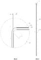
- FIG. 1 is a structure view of an embodiment of a direct-type panel lamp of the present invention
- FIG. 2 is an exploded view of the direct-type panel lamp shown in FIG. 1 ;
- FIG. 3 is a structure view of FIG. 1 in which a frame bar is not shown;
- FIG. 4 is a partial view of the direct-type panel lamp shown in FIG. 1 ;
- FIG. 5 is an enlarged view of the portion A shown in FIG. 4 ;
- FIG. 6 is a structure view of the first convex rib and the frame
- FIG. 7 is a structure view of the back plate shown in FIG. 1 ;
- FIG. 8 is an enlarged view of the portion B shown in FIG. 7 ;
- FIG. 9 is a structure view of the back plate shown in FIG. 1 ;
- FIG. 10 is an enlarged view of the portion C shown in FIG. 9 ;
- FIG. 11 is an enlarged view of the portion D shown in FIG. 9 ;
- FIG. 12 is a structure view of the frame bar shown in FIG. 1 ;
- FIG. 13 is a structure view showing an arrangement for connecting the light bars
- FIG. 14 is a structure view of the flexible strip being connected with the substrate in FIG. 13 ;
- FIG. 15 is a structure view of the LED lamp beads and the lenses in FIG. 13 ;
- FIG. 16 is a structure view of the substrate in FIG. 13 ;
- FIG. 17 is a structure view of the flexible strip in FIG. 13 ;
- FIG. 18 is a structure view showing the light emitted by the LED lamp beads passing through the lenses and being diffused;
- FIG. 19 is a structure view showing the light emitted by the LED lamp beads passing through the lenses and being diffused;
- FIG. 20 is an exploded view of another embodiment of a direct-type panel lamp
- FIG. 21 is a partial structure view of the direct-type panel lamp in FIG. 20 ;
- FIG. 22 is a structure view showing the compensation bar matching with the frame
- FIG. 23 is a structure view of the compensation bar in FIG. 22 ;
- a component when a component is “connected” with another component, it may be directly connected to another component or may be indirectly connected to another component through a further component.
- a component when a component is “provided” on another component, it may be directly provided on another component or may be provided on another component through a further component.
- the present application provides a direct-type panel lamp 100 , which includes a frame 40 , a back plate 20 , a diffusion plate 30 , and at least one light bar 10 .
- the back plate 20 has a shell-like structure formed by deforming a sheet metal, and the shell-like structure includes a center area 21 and an edge area 22 surrounding the center area 21 .
- the center area 21 is arched to increase the distance to the diffusion plate 30 and is configured to install and fix the light bar 10 .
- the light bar 10 includes a substrate 11 , LED lamp beads 12 fixed on the substrate 11 and lenses 13 respectively covered on the LED lamp beads 12 .
- the light bar 10 is fixed on the side of the center area 21 of the back plate 20 facing the diffusion plate 30 .
- the diffusion plate 30 has a light-transmitting function. The light emitted by the LED lamp beads 12 passes through the lenses 13 and the diffusion plate 30 in sequence and diffused by the later, so that LED point light sources become a uniform planar light source.
- the frame 40 is formed by connecting several (usually four) frame bars 41 end-to-end.
- Each frame bar 41 has a first mounting surface 42 and a second mounting surface 43 which are located at different levels.
- the edge of the diffusion plate 30 overlaps on the first mounting surface 42 at the lower level, and the edge area 22 of the back plate 20 overlaps on the second mounting surface 43 at the higher level and is fixed by fastening screws.
- the back plate 20 is made of a sheet metal, and the light bar 10 is installed in the center area of the back plate 20 .
- the center area of the back plate 20 may sag, causing the corners of the back plate 20 to turn up.
- the frame may be pulled to deform and warp.
- the edge area 22 of the back plate 20 is deformed and forms first convex ribs 24 extending along the peripheral sides of the back plate 20 .
- the first convex ribs 24 can increase the support strength of the entire back plate 20 , especially the support strength of the edge area 22 .
- the deformation of the edge area 22 can be reduced, so that the edge area 22 is always in a flat state, so as to prevent it from pulling the frame 40 and thus deforming the frame 40 . Therefore, the direct-type panel lamp 100 can be closely attached to the keel on the ceiling, without gap therebetween.
- the first convex ribs 24 press the edge of the diffusion plate 30 to abut against the first mounting surface 42 . Since the back plate 20 has a certain elasticity, when the first convex ribs 24 abut against the diffusion plate 30 , the first convex ribs 24 are elastically deformed, such that the first convex ribs 24 exert pressure on the diffusion plate 30 .
- the edge of the diffusion plate 30 is sandwiched between the first convex ribs 24 and the first mount surface 42 to avoid deformation, so that the central part of the diffusion plate (the geometric center of the diffusion plate 30 or the part around the geometric center of the diffusion plate 30 ) is prevented from sagging downward.
- the deformation of the back plate 20 is always inevitable, which can be reduced by providing a plurality of convex ribs.
- the first convex rib 24 on each peripheral side of the back plate 20 has a height gradually increasing from a middle thereof towards two ends thereof, respectively, so as to counteract the deformation of the back plate 20 .
- two first convex ribs 24 on adjacent peripheral sides of the back plate 20 are connected with each other.
- the highest height of the first convex rib 24 is provided as H 1
- H 1 : H 2 1.05 ⁇ 1.08: 1.
- the height of the highest height of the first convex rib 24 is 4.2 mm, and the lowest height of the first convex rib 24 is 4 mm.
- included angles are provided between the portion of the edge area 22 overlapping the second mounting surface 43 and the second mounting surface 43 , and the included angles gradually decrease from a respective end of the frame bar 41 to the middle of the frame bar 41 , which can also counteract the deformation of the back plate 20 .
- ⁇ 1 The maximum included angle between the portion of the edge area 22 overlapping the second mounting surface 43 and the second mounting surface 43 is provided as ⁇ 1
- ⁇ 1 is 5 degrees
- ⁇ 2 is 4 degrees.
- the included angle between the portion of the edge area 22 overlapping the second mounting surface 43 and the second mounting surface 43 ranges from 3 degrees to 10 degrees.
- the included angle between the portion of the edge area 22 overlapping the second mounting surface 43 and the second mounting surface 43 ranges from 3 degrees to 8 degrees.
- the interference (for example, denoted as X in FIG. 6 ) of the distance between the first convex ribs 24 and the diffusion plate 30 relative to the thickness of the diffusion plate is less than 0.5 mm, wherein the pressure from the back plate 20 to the diffusion plate 30 ranges from 0 to 100 N.
- the interference of the distance between the first convex ribs 24 and the diffusion plate 30 relative to the thickness of the diffusion plate is less than 0.3 mm, such that the pressure from the back plate 20 to the diffusion plate 30 is controlled within 0 to 50N.
- the edge area 22 of the back plate 20 forms second convex ribs 25 extending along the peripheral sides of the back plate 20 .
- the second convex ribs 25 and the first convex ribs 24 cooperate with each other to increase the supporting strength of the entire back plate 20 , especially the supporting strength of the edge area 22 .
- the deformation of the edge area 22 can be reduced, so that the edge area 22 is always in a flat state. It is prevented from pulling and thus deforming the frame 40 , so that the direct-type panel lamp 100 can be closely attached to the keel on the ceiling, without gap therebetween.
- the edge area 22 is bent to form the first convex ribs 24 and the second convex ribs 25 .
- the edge area 22 is bent using conventional processing methods, such as mechanical stamping or the like.
- first convex rib 24 and the second convex rib 25 are arranged in parallel, and the second convex ribs 25 are located outside of the first convex ribs 24 to facilitate the installation of the back plate.
- the frame bars 41 are made of metal profile (such as aluminum alloy), and the adjacent ends of the adjacent frame bars 41 are welded and fixed.
- the frame bars 41 may be formed by injection molding polymer materials. In this case, since polymer materials cannot be welded, it is generally necessary to provide corner pieces at the corners of the frame 40 to connect adjacent frame bars 41 .
- adjacent frame bars 41 may be connected by overlapping and connecting with each other. However, the flatness of a frame 40 made of polymer materials is poorer than that of a frame 40 made of metal profile.
- the frame bar 41 has an L-shaped cross section, and includes a horizontal portion 44 and a vertical portion 45 .
- the edge of the diffusion plate 30 and the edge of the back plate 20 are both overlapped on the horizontal portions 44 .
- the vertical portion 45 encloses a confined space, and functions to shield the structure of the back plate 20 at the edge and have a decorative and protective effect.
- the thickness of the corner of the frame bar 41 is increased inside to form a thickened portion 46 , thereby forming a stepped structure at the horizontal portion 44 .
- the first mounting surface 42 and the second mounting surface 43 are provided on the stepped structure and the horizontal portion 44 respectively.
- the thickened portion may have a hollow structure.
- both the first convex rib 24 and the second convex rib 25 have a U-shaped cross section, and the two U-shaped structures are opened to opposite directions.
- the U-shaped structure of the first convex rib 24 opens upward, and the U-shaped structure of the second convex rib 25 opens downward.
- the height of the first convex rib 24 is L 1 and the width thereof is L 2
- the height of the second convex rib 25 is L 3
- the width thereof is L 4
- L 1 : L 3 3-10
- L 2 : L 4 3-10
- L 1 : L 3 3 ⁇ 10
- L 2 : L 4 3 ⁇ 10.
- the height of the first convex rib 24 is 4.2 mm and the width thereof is 2.3 mm
- the height of the second convex rib 25 is 0.6 mm and the width thereof is 0.7 mm.
- the height of the first convex rib 24 and the height of the second convex rib 25 refer to the respective lengths of the first convex rib 24 and the second convex rib 25 along the vertical direction, and the width direction of the first convex rib 24 and the width direction of the second convex rib 25 are perpendicular to the vertical direction.
- the second convex ribs 25 extend at intervals or continuously along the peripheral sides of the back plate 20 . In the present embodiment, the second convex ribs 25 extend continuously along the peripheral sides of the back plate 20 .
- the distance L 2 between the first convex ribs 24 and the edge of the back plate 20 ranges from 4 mm to 10 mm.
- the distance L 2 between the first convex ribs 24 and the edge of the back plate 20 is 5 mm.
- the back plate 20 is stamped from a sheet metal (such as ST13) to form an arched shell-like structure, so that a certain distance is formed between the back plate 20 and the diffusion plate 30 , and thus the light bar 10 can be accommodated.
- the back plate 20 is arched to form a chamber 23 comprising a flat bottom wall 231 and an inclined side wall 232 , wherein the bottom wall 231 and the diffusion plate 30 are arranged in parallel.
- the at least one light bar 10 is fixed on the bottom wall 231 .
- the side wall 232 is tangentially connected with the first convex ribs 24 .
- the light bar 10 is installed on the bottom surface of the bottom wall 231 .
- the portion of the edge area 22 overlapping the frame 40 is parallel to the bottom wall 231 , and the bottom wall 231 is higher than the edge area 22 .
- the bottom wall 231 is arranged horizontally, and the corresponding portion of the edge area 22 overlapping the frame 40 is also arranged horizontally.
- the bottom wall 231 defines grooves arranged in a crisscross pattern for receiving the at least one light bar 10 .
- the center area 21 of the back plate 20 is stamped to form a plurality of protrusions 211 facing away from the chamber 23 , and the grooves are formed between adjacent protrusions 211 . Since the light bars 10 are all arranged in parallel, the protrusions 211 should also be arranged in parallel. The gap between two adjacent protrusions 211 functions to receive the light bar 10 , so the light bar 10 generally has a straight bar structure. Alternatively, the light bar may also have a coiled structure.
- the edge area 22 of the back plate 20 is fixed on the frame 40 by fastening screws.
- the frame bar 41 is provided with a screw groove 471 arranged along the longitudinal direction thereof.
- the middle portion of the upper surface of the horizontal portion 44 is provided with a vertical portion 47 , the gap between the vertical portion 47 and the stepped structure forms the screw groove 471 , and the top surface of the vertical portion 47 supports the edge area 22 .
- the thickness of the back plate 20 ranges from 0.2 mm to 0.4 mm.
- the thickness of the back plate 20 is 0.3 mm.
- the substrate 11 may be a metal substrate, preferably an aluminum substrate, or an FR-4 glass fiber substrate. In some embodiments, the surface of the substrate 11 is coated with white solder resist ink to improve light reflection efficiency.
- the substrate 11 may be fixed to the bottom surface of the back plate 20 by screws, and is preferably fixed to the bottom surface of the back plate 20 by thermally conductive glue.
- adjacent light bars 10 are connected in parallel by wires or flexible strips 14 .
- the LED lamp beads 12 are distributed in a matrix form on the inner side of the back plate 20 , so that the light sources are evenly distributed and at the same time easy to install.
- the substrate 11 includes a metal layer 111 , an insulating layer 112 and a circuit layer 113 , and the LED lamp beads 12 are soldered on the circuit layer 113 .
- Solder pads 115 for welding the LED lamp beads 12 are usually provided on the circuit layer 113 .
- the surface of the substrate 11 is coated with white solder resist ink to form a solder resist layer 144 , with openings formed at the solder pads 115 to expose the solder pads 115 for welding the LED lamp beads 12 .
- Lenses 13 of the light bar 10 mainly function to diffuse light.
- the lenses 13 are fixed on the substrate 11 by epoxy glue or UV glue.
- protruding legs 131 are provided on the back side of the lens 13 , and positioning holes engaging with the protruding legs 131 are provided on the corresponding substrate 11 .
- the flexible strip 14 is pressed on all the light bars 10 and perpendicularly intersects all the light bars 10 to facilitate the welding of the light bars 10 and the flexible strip 14 .
- the flexible strip 14 has a strip-shaped structure and includes an insulating layer 142 , a circuit layer 143 and a solder resist layer 144 .
- the insulating layer 142 is made of insulating resin material.
- the solder resist layer 144 is formed by white solder resist ink coated on the surface, so that the flexible strip 14 can also reflect light.
- first openings 141 are defined at the edges of the flexible strip 14 that are not coated with solder resist ink
- second openings 114 are defined at the positions of the substrate 11 close to the flexible strip 14 that are not coated with solder resist ink, with solder pads provided at first and second openings that are electrically connected by welding.
- the bottom surface of the back plate 20 is provided with a white reflective coating.
- the reflective coating may be formed using various metal coating materials, including epoxy resin, UV resin, and the like.
- the light passes through the lens 13 and projects on the diffusion plate 30 to form a circular light spot.
- the light spots should cover the entire diffusion plate 30 .
- the diameter D of the light spot is not less than the distance between the two adjacent LED lamp beads 12 on the same diagonal. Because the intensity of the light spot is large in the middle portion thereof and small in the edge portion thereof, the adjacent light spots are partially overlapped, so that the light from the diffusion plate 30 is approximately uniform.
- the beam angle of the lens 13 is R
- the vertical distance between the LED lamp bead 12 and the diffusion plate 30 is d, in the case where all points of the diffusion plate 30 are projected by light, the relationship
- the beam angle of the lens 13 is 168°, and generally should not be less than 160°, so that the thickness of the panel lamp can reach 20-30 mm, and the distance between the LED lamp beads 12 can reach 50-80 mm.
- direct-type panel lamp 100 is provided with a driving module, and the flexible strip 14 is electrically connected to the driving module via wires.
- the driving module is usually arranged in a driving box 50 .
- the driving box 50 is arranged in the gap between the back plate 20 and the vertical portion 45 , and the top surface of the driving box 50 is lower than the top surface of the back plate 20 or the vertical portion 45 , so that the driving box 50 would not be exposed outside, and thus an external force can be prevented from exerting on the driving box 50 .
- the driving box 50 is also fixed in the gap by the fastening screws screwed into the screw groove 471 .
- the driving box 50 includes a box body with an opening, and a top cover snap-fit at the opening of the box body.
- the driving module is placed in the box body, and two ends of the box body are provided with wire openings for the connection wires of the driving module to pass through. In the case where the driving module needs to be replaced or repaired, it is only required to take the driving module out of the box body, which simplifies the maintenance or replacement of the driving module.
- Two ends of the box body are provided with tabs extending toward the outside of the box body, and the tabs are fixed on the frame 40 by fastening screws, and the bottom surfaces of the tabs are flush with the bottom surface of the box body.
- the tabs and the box body are formed in one piece.
- the direct-type panel lamp 100 further includes a compensation bar 60 .
- the compensation bar 60 is arranged between the edge area 22 and the second mounting surface 43 , and close to the corner of the frame 40 .
- the thickness of the compensation bar 60 gradually decreases from the respective end to the center of the frame bar 41 .
- the compensation bar 60 lifts the edge area 22 (to increase the distance of the gap between the edge area 22 and the frame bar 41 ), in order to counteract the warpage caused by the unflattened bottom edge of the back plate 20 , and to prevent the back plate 20 from pulling and thus deforming the frame 40 , so that the direct-type panel lamp 100 can be closely attached to the keel on the ceiling, without gap therebetween.
- the edge area 22 of the back plate 20 is deformed and forms a convex rib 26 extending along the peripheral sides of the back plate 20 , the convex rib 26 can increase the supporting strength of the entire back plate 26 , especially the supporting strength of the edge area 22 .
- the edge area 22 is bent using conventional processing methods, such as mechanical stamping or the like.
- convex ribs 26 may refer to the first convex ribs 24 and the second convex ribs 25 in the foregoing embodiment.
- the compensation bar 60 is made of plastic material such as polyvinyl chloride.
- the compensation bar 60 may be made of metal such as aluminum or ENA cotton or the like.
- one of the compensation bar 60 and the frame 40 is provided with a positioning groove
- the other is provided with a positioning pin 61 that is matched with the positioning groove.
- the outer contour of the positioning pin 61 generally corresponds to the contour of the positioning groove.
- the cross section of the positioning pin 61 is non-circular (for example, in the present embodiment, the cross section of the positioning pin 61 is oval).
- the cross section of positioning pins 61 is not strictly limited.
- the compensation bar 60 is L-shaped, and includes a first compensation portion 62 and a second compensation portion 63 .
- the junction between the first compensation portion 62 and the second compensation portion 63 is aligned with the junction of two adjacent frame bars 41 , and the first compensation portion 62 and the second compensation portion 63 respectively extends toward the center of the frame bars 41 .
- the thickness of the first compensation portion 62 and the thickness of the second compensation portion 63 both gradually decrease from the end of the respective frame bars to the center of the respective frame bars.
- the first compensation portion 62 and the second compensation portion 63 may formed in one piece, which can simplify the processing of the compensation bar 60 and increase the structural strength of the compensation bar 60 .
- the first compensation portion 62 and the second compensation portion 63 may formed in separate pieces.
- the positioning pin 61 has a longitudinal direction, and gradually tapers from one end to the other end along the longitudinal direction, wherein the larger end of the positioning pin 61 is connected to the compensation bar or the frame bar.
- the side walls of the positioning pin 61 can be attached to at least two inner walls of the positioning slot.
- the positioning pins 61 are provided on the compensation bar 60 , the number of the positioning pins 61 is at least two, and the positioning pins 61 are arranged in sequence along the extension direction of the compensation bar 60 .
- the positioning pin 61 and the compensation bar 60 may be connected by bonding or welding or the like. In order to strengthen the connection strength between the positioning pin 61 and the compensation bar 60 and simplify the processing of the junction between the positioning pin 61 and the compensation bar 60 , in one of the embodiments, the positioning pin 61 and the compensation bar 60 are formed in one piece.
- the included angle between the top surface and the bottom surface of the compensation bar 60 ranges from 1 degree to 5 degrees, wherein, the top surface of the compensation bar 60 is the surface in contact with the edge area 22 , and the bottom surface of the compensation bar 60 is the surface in contact with the second mounting surface 43 .
- the included angle between the top surface and the bottom surface of the compensation bar 60 ranges from 1 degree to 2 degrees.
- the greatest thickness of the compensation bar 60 is 2.5 mm, the smallest thickness is 1.5 mm, and the width is 7 mm.
- the screw groove 471 is configures as the positioning groove, and the fastening screw for fixing the back plate 20 passes through the edge area 22 and the compensation bar 60 in sequence.
- the compensation bar can counteract the warping caused by the unflattened bottom edge of the back plate, and avoid the back plate from pulling and thus deforming the frame thus the direct-type panel lamp can be closely attached to keel on the ceiling, without gap therebetween.
Landscapes
- Engineering & Computer Science (AREA)
- General Engineering & Computer Science (AREA)
- Planar Illumination Modules (AREA)
Abstract
Description
should be satisfied.
Claims (20)
Applications Claiming Priority (10)
| Application Number | Priority Date | Filing Date | Title |
|---|---|---|---|
| CN202022461228.4U CN213983266U (en) | 2020-10-29 | 2020-10-29 | Direct type panel light |
| CN202022457220.0 | 2020-10-29 | ||
| CN202022459389.X | 2020-10-29 | ||
| CN202022461228.4 | 2020-10-29 | ||
| CN202022459354.6 | 2020-10-29 | ||
| CN202022457220.0U CN213983262U (en) | 2020-10-29 | 2020-10-29 | Direct type panel light |
| CN202022458501.8U CN213983263U (en) | 2020-10-29 | 2020-10-29 | Direct type panel lamp |
| CN202022459389.XU CN213983265U (en) | 2020-10-29 | 2020-10-29 | Direct type panel light |
| CN202022458501.8 | 2020-10-29 | ||
| CN202022459354.6U CN213983264U (en) | 2020-10-29 | 2020-10-29 | Direct type panel light |
Publications (2)
| Publication Number | Publication Date |
|---|---|
| US20220136680A1 US20220136680A1 (en) | 2022-05-05 |
| US11435061B2 true US11435061B2 (en) | 2022-09-06 |
Family
ID=81378858
Family Applications (1)
| Application Number | Title | Priority Date | Filing Date |
|---|---|---|---|
| US17/172,020 Active US11435061B2 (en) | 2020-10-29 | 2021-02-09 | Direct-type panel lamp |
Country Status (1)
| Country | Link |
|---|---|
| US (1) | US11435061B2 (en) |
Families Citing this family (5)
| Publication number | Priority date | Publication date | Assignee | Title |
|---|---|---|---|---|
| USD960422S1 (en) * | 2020-05-11 | 2022-08-09 | Xiamen Pvtech Co., Ltd. | Panel light |
| USD1111221S1 (en) * | 2022-05-10 | 2026-02-03 | TieJun Wang | Direct lighting panel |
| CN218327615U (en) * | 2022-09-09 | 2023-01-17 | 惠州市晶辉科技有限公司 | An integrated lamp panel surface frame and an integrated panel lamp without a surface frame |
| CN115751233A (en) * | 2022-11-24 | 2023-03-07 | 厦门普为光电科技有限公司 | Ultrathin narrow-frame panel lamp |
| USD1086534S1 (en) * | 2023-09-19 | 2025-07-29 | Ningbo Morelux Lighting Mfg Ltd | Panel light |
Citations (7)
| Publication number | Priority date | Publication date | Assignee | Title |
|---|---|---|---|---|
| CN102518997A (en) * | 2011-12-01 | 2012-06-27 | 青岛海信电器股份有限公司 | Backlight module and television |
| KR101177481B1 (en) * | 2012-04-02 | 2012-08-24 | 엘지전자 주식회사 | Lighting apparatus |
| KR20120104047A (en) * | 2011-03-11 | 2012-09-20 | 나노엘이디(주) | Lighting apparatus with led |
| US20140240978A1 (en) * | 2013-02-28 | 2014-08-28 | Eun Hwa KIM | Illuminating apparatus |
| KR101459096B1 (en) * | 2014-06-10 | 2014-11-13 | (주)프로맥엘이디 | Case of flat type LED lamp and manufacturing method thereof |
| US20150055353A1 (en) * | 2013-08-20 | 2015-02-26 | Lsi Industries, Inc. | Luminaire Mounting Structure |
| US20170009960A1 (en) * | 2015-07-06 | 2017-01-12 | Samsung Electronics Co., Ltd. | Backlight unit of display apparatus and display apparatus |
-
2021
- 2021-02-09 US US17/172,020 patent/US11435061B2/en active Active
Patent Citations (7)
| Publication number | Priority date | Publication date | Assignee | Title |
|---|---|---|---|---|
| KR20120104047A (en) * | 2011-03-11 | 2012-09-20 | 나노엘이디(주) | Lighting apparatus with led |
| CN102518997A (en) * | 2011-12-01 | 2012-06-27 | 青岛海信电器股份有限公司 | Backlight module and television |
| KR101177481B1 (en) * | 2012-04-02 | 2012-08-24 | 엘지전자 주식회사 | Lighting apparatus |
| US20140240978A1 (en) * | 2013-02-28 | 2014-08-28 | Eun Hwa KIM | Illuminating apparatus |
| US20150055353A1 (en) * | 2013-08-20 | 2015-02-26 | Lsi Industries, Inc. | Luminaire Mounting Structure |
| KR101459096B1 (en) * | 2014-06-10 | 2014-11-13 | (주)프로맥엘이디 | Case of flat type LED lamp and manufacturing method thereof |
| US20170009960A1 (en) * | 2015-07-06 | 2017-01-12 | Samsung Electronics Co., Ltd. | Backlight unit of display apparatus and display apparatus |
Also Published As
| Publication number | Publication date |
|---|---|
| US20220136680A1 (en) | 2022-05-05 |
Similar Documents
| Publication | Publication Date | Title |
|---|---|---|
| US11435061B2 (en) | Direct-type panel lamp | |
| US11530787B2 (en) | Collapse preventing lamps | |
| US11313545B1 (en) | Direct-type panel lamp with adjustable light emitting function | |
| US11231161B1 (en) | Direct-type panel lamp with uniform light | |
| CN211738672U (en) | Direct type panel lamp | |
| US11287120B2 (en) | Direct-type panel lamp with driving box and package structure thereof | |
| US20130044460A1 (en) | Backlight unit and lighting system including the same | |
| US20080259609A1 (en) | Led lamp assembly | |
| CN213983262U (en) | Direct type panel light | |
| KR20240000042U (en) | Direct type panel lamp capable of emitting light uniformly | |
| CN211738839U (en) | Straight following formula panel light convenient to installation | |
| CN109764286A (en) | A direct type luminous panel light | |
| US11536425B1 (en) | Lamp and lamp mounting structure | |
| CN213983264U (en) | Direct type panel light | |
| US12392475B2 (en) | LED lighting device | |
| CN217302724U (en) | Panel light | |
| CN211925691U (en) | Driving box and direct type panel lamp | |
| KR20240000043U (en) | Direct type panel lamp with flat appearance | |
| CN211738669U (en) | Direct type panel lamp with uniform light emission | |
| EP3929483B1 (en) | Panel light | |
| CN213983265U (en) | Direct type panel light | |
| CN213983263U (en) | Direct type panel lamp | |
| CN213983266U (en) | Direct type panel light | |
| CN216280966U (en) | Mounting structure of panel light | |
| CN113390038A (en) | Straight following formula panel light convenient to installation |
Legal Events
| Date | Code | Title | Description |
|---|---|---|---|
| AS | Assignment |
Owner name: CH LIGHTING TECHNOLOGY CO., LTD., CHINA Free format text: ASSIGNMENT OF ASSIGNORS INTEREST;ASSIGNORS:ZHANG, JUNYU;HANG, ZEGANG;PU, JIZHONG;AND OTHERS;REEL/FRAME:055266/0709 Effective date: 20210125 |
|
| FEPP | Fee payment procedure |
Free format text: ENTITY STATUS SET TO UNDISCOUNTED (ORIGINAL EVENT CODE: BIG.); ENTITY STATUS OF PATENT OWNER: LARGE ENTITY |
|
| AS | Assignment |
Owner name: CH LIGHTING TECHNOLOGY CO., LTD., CHINA Free format text: CORRECTIVE ASSIGNMENT TO CORRECT THE CONVEYING PARTY BY EXPUNGED THE 4TH AND 5TH INVENTOR'S NAME PREVIOUSLY RECORDED AT REEL: 055266 FRAME: 0709. ASSIGNOR(S) HEREBY CONFIRMS THE ASSIGNMENT;ASSIGNORS:ZHANG, JUNYU;HANG, ZEGANG;PU, JIZHONG;REEL/FRAME:056680/0640 Effective date: 20210125 |
|
| STPP | Information on status: patent application and granting procedure in general |
Free format text: RESPONSE TO NON-FINAL OFFICE ACTION ENTERED AND FORWARDED TO EXAMINER |
|
| STPP | Information on status: patent application and granting procedure in general |
Free format text: NOTICE OF ALLOWANCE MAILED -- APPLICATION RECEIVED IN OFFICE OF PUBLICATIONS |
|
| STPP | Information on status: patent application and granting procedure in general |
Free format text: PUBLICATIONS -- ISSUE FEE PAYMENT VERIFIED |
|
| STCF | Information on status: patent grant |
Free format text: PATENTED CASE |
|
| MAFP | Maintenance fee payment |
Free format text: PAYMENT OF MAINTENANCE FEE, 4TH YEAR, LARGE ENTITY (ORIGINAL EVENT CODE: M1551); ENTITY STATUS OF PATENT OWNER: LARGE ENTITY Year of fee payment: 4 |