US11433899B2 - Method, apparatus and system for detecting obstacle collision in automatic parking path - Google Patents
Method, apparatus and system for detecting obstacle collision in automatic parking path Download PDFInfo
- Publication number
- US11433899B2 US11433899B2 US16/732,249 US201916732249A US11433899B2 US 11433899 B2 US11433899 B2 US 11433899B2 US 201916732249 A US201916732249 A US 201916732249A US 11433899 B2 US11433899 B2 US 11433899B2
- Authority
- US
- United States
- Prior art keywords
- contour
- path
- line segment
- obstacle
- circular arc
- Prior art date
- Legal status (The legal status is an assumption and is not a legal conclusion. Google has not performed a legal analysis and makes no representation as to the accuracy of the status listed.)
- Active, expires
Links
Images


Classifications
-
- B—PERFORMING OPERATIONS; TRANSPORTING
- B60—VEHICLES IN GENERAL
- B60W—CONJOINT CONTROL OF VEHICLE SUB-UNITS OF DIFFERENT TYPE OR DIFFERENT FUNCTION; CONTROL SYSTEMS SPECIALLY ADAPTED FOR HYBRID VEHICLES; ROAD VEHICLE DRIVE CONTROL SYSTEMS FOR PURPOSES NOT RELATED TO THE CONTROL OF A PARTICULAR SUB-UNIT
- B60W40/00—Estimation or calculation of non-directly measurable driving parameters for road vehicle drive control systems not related to the control of a particular sub unit, e.g. by using mathematical models
- B60W40/02—Estimation or calculation of non-directly measurable driving parameters for road vehicle drive control systems not related to the control of a particular sub unit, e.g. by using mathematical models related to ambient conditions
-
- B—PERFORMING OPERATIONS; TRANSPORTING
- B60—VEHICLES IN GENERAL
- B60W—CONJOINT CONTROL OF VEHICLE SUB-UNITS OF DIFFERENT TYPE OR DIFFERENT FUNCTION; CONTROL SYSTEMS SPECIALLY ADAPTED FOR HYBRID VEHICLES; ROAD VEHICLE DRIVE CONTROL SYSTEMS FOR PURPOSES NOT RELATED TO THE CONTROL OF A PARTICULAR SUB-UNIT
- B60W30/00—Purposes of road vehicle drive control systems not related to the control of a particular sub-unit, e.g. of systems using conjoint control of vehicle sub-units
- B60W30/08—Active safety systems predicting or avoiding probable or impending collision or attempting to minimise its consequences
- B60W30/095—Predicting travel path or likelihood of collision
- B60W30/0953—Predicting travel path or likelihood of collision the prediction being responsive to vehicle dynamic parameters
-
- B—PERFORMING OPERATIONS; TRANSPORTING
- B60—VEHICLES IN GENERAL
- B60W—CONJOINT CONTROL OF VEHICLE SUB-UNITS OF DIFFERENT TYPE OR DIFFERENT FUNCTION; CONTROL SYSTEMS SPECIALLY ADAPTED FOR HYBRID VEHICLES; ROAD VEHICLE DRIVE CONTROL SYSTEMS FOR PURPOSES NOT RELATED TO THE CONTROL OF A PARTICULAR SUB-UNIT
- B60W30/00—Purposes of road vehicle drive control systems not related to the control of a particular sub-unit, e.g. of systems using conjoint control of vehicle sub-units
- B60W30/08—Active safety systems predicting or avoiding probable or impending collision or attempting to minimise its consequences
- B60W30/095—Predicting travel path or likelihood of collision
- B60W30/0956—Predicting travel path or likelihood of collision the prediction being responsive to traffic or environmental parameters
-
- B—PERFORMING OPERATIONS; TRANSPORTING
- B60—VEHICLES IN GENERAL
- B60W—CONJOINT CONTROL OF VEHICLE SUB-UNITS OF DIFFERENT TYPE OR DIFFERENT FUNCTION; CONTROL SYSTEMS SPECIALLY ADAPTED FOR HYBRID VEHICLES; ROAD VEHICLE DRIVE CONTROL SYSTEMS FOR PURPOSES NOT RELATED TO THE CONTROL OF A PARTICULAR SUB-UNIT
- B60W30/00—Purposes of road vehicle drive control systems not related to the control of a particular sub-unit, e.g. of systems using conjoint control of vehicle sub-units
- B60W30/06—Automatic manoeuvring for parking
-
- B—PERFORMING OPERATIONS; TRANSPORTING
- B60—VEHICLES IN GENERAL
- B60W—CONJOINT CONTROL OF VEHICLE SUB-UNITS OF DIFFERENT TYPE OR DIFFERENT FUNCTION; CONTROL SYSTEMS SPECIALLY ADAPTED FOR HYBRID VEHICLES; ROAD VEHICLE DRIVE CONTROL SYSTEMS FOR PURPOSES NOT RELATED TO THE CONTROL OF A PARTICULAR SUB-UNIT
- B60W50/00—Details of control systems for road vehicle drive control not related to the control of a particular sub-unit, e.g. process diagnostic or vehicle driver interfaces
- B60W50/0097—Predicting future conditions
-
- B—PERFORMING OPERATIONS; TRANSPORTING
- B62—LAND VEHICLES FOR TRAVELLING OTHERWISE THAN ON RAILS
- B62D—MOTOR VEHICLES; TRAILERS
- B62D15/00—Steering not otherwise provided for
- B62D15/02—Steering position indicators ; Steering position determination; Steering aids
- B62D15/027—Parking aids, e.g. instruction means
- B62D15/0285—Parking performed automatically
-
- G—PHYSICS
- G01—MEASURING; TESTING
- G01C—MEASURING DISTANCES, LEVELS OR BEARINGS; SURVEYING; NAVIGATION; GYROSCOPIC INSTRUMENTS; PHOTOGRAMMETRY OR VIDEOGRAMMETRY
- G01C21/00—Navigation; Navigational instruments not provided for in groups G01C1/00 - G01C19/00
- G01C21/20—Instruments for performing navigational calculations
-
- G—PHYSICS
- G05—CONTROLLING; REGULATING
- G05D—SYSTEMS FOR CONTROLLING OR REGULATING NON-ELECTRIC VARIABLES
- G05D1/00—Control of position, course, altitude or attitude of land, water, air or space vehicles, e.g. using automatic pilots
- G05D1/02—Control of position or course in two dimensions
- G05D1/021—Control of position or course in two dimensions specially adapted to land vehicles
- G05D1/0212—Control of position or course in two dimensions specially adapted to land vehicles with means for defining a desired trajectory
- G05D1/0214—Control of position or course in two dimensions specially adapted to land vehicles with means for defining a desired trajectory in accordance with safety or protection criteria, e.g. avoiding hazardous areas
-
- B—PERFORMING OPERATIONS; TRANSPORTING
- B60—VEHICLES IN GENERAL
- B60W—CONJOINT CONTROL OF VEHICLE SUB-UNITS OF DIFFERENT TYPE OR DIFFERENT FUNCTION; CONTROL SYSTEMS SPECIALLY ADAPTED FOR HYBRID VEHICLES; ROAD VEHICLE DRIVE CONTROL SYSTEMS FOR PURPOSES NOT RELATED TO THE CONTROL OF A PARTICULAR SUB-UNIT
- B60W2554/00—Input parameters relating to objects
- B60W2554/20—Static objects
-
- B—PERFORMING OPERATIONS; TRANSPORTING
- B60—VEHICLES IN GENERAL
- B60W—CONJOINT CONTROL OF VEHICLE SUB-UNITS OF DIFFERENT TYPE OR DIFFERENT FUNCTION; CONTROL SYSTEMS SPECIALLY ADAPTED FOR HYBRID VEHICLES; ROAD VEHICLE DRIVE CONTROL SYSTEMS FOR PURPOSES NOT RELATED TO THE CONTROL OF A PARTICULAR SUB-UNIT
- B60W2554/00—Input parameters relating to objects
- B60W2554/80—Spatial relation or speed relative to objects
-
- G05D2201/0213—
Definitions
- the present application relates to an automatic detection technology, and in particular, to a method, apparatus and system for detecting obstacle collision in a parking path in the process of automatic parking.
- the automatic parking technologies can help people to complete parking safely and reliably. It uses on-board sensors to detect an available parking space, then plans an executable path, and then automatically controls the vehicle to follow the path to complete parking. It can be seen that path planning is a key part of the automatic parking technology, and its basic requirements include: feasible path, safe and collision free, simple and efficient algorithm. Where, the safe and collision free and the simple and efficient algorithm are very important to the path planning algorithm. However, the collision detection in the commonly used path planning method for automatic parking has the problem of low detection efficiency, so it is difficult to meet the requirements of automatic parking path planning.
- a first purpose of the present application is to provide an efficient method for detecting obstacle collision in an automatic parking path.
- a second purpose of the present application is to provide an efficient apparatus for detecting obstacle collision in an automatic parking path.
- a third purpose of the present application is to provide an efficient system for detecting obstacle collision in an automatic parking path.
- a first technical solution adopted in the present application is: a method for detecting obstacle collision in an automatic parking path, including the following steps:
- the path contour is a boundary contour formed by a vehicle traveling from a start point pose to an end point pose along the path
- the path contour includes a circular arc path contour and/or a straight line path contour
- the vehicle contour is a polygon
- the obstacle contour is a line segment.
- step of geometrically performing an obstacle collision detection in a circular arc path includes the following sub-steps:
- the obvious non-collision condition includes any one of the following conditions:
- distances between both end points of the line segment of the obstacle and a center of a circle corresponding to the circular arc path contour are all less than a first radius, the first radius being a radius corresponding to an inside circular arc segment in the circular arc path contour;
- the minimum distance from the center of the circle corresponding to the circular arc path contour to the line segment of the obstacle is greater than a second radius, the second radius being a radius corresponding to an outside circular arc segment in the circular arc path contour;
- both end points of the line segment of the obstacle are within a range of a fourth central angle, the fourth central angle being a group angle of a central angle corresponding to a planned path.
- the step of determining whether the line segment of the obstacle intersects with the circular arc path contour includes the following sub-steps:
- the straight line equation refers to an equation of a straight line where the line segment of the obstacle is located
- the circle equation includes an equation of a first circle where the inside circular arc segment in the circular arc path contour is located and an equation of a second circle where the outside circular arc segment in the circular arc path contour is located;
- the step of determining whether the line segment of the obstacle is located in the circular arc path contour includes the following sub-steps:
- the first region refers to a region that is within the circular ring segment of the circular arc path and does not belong to a region where the path interferes with the vehicle contour.
- the step of determining whether the line segment of the obstacle is located in a circular ring segment of the circular arc path includes the following sub-steps:
- step of determining whether the line segment of the obstacle intersects with an end point vehicle contour includes the following sub-steps:
- step of determining whether the line segment of the obstacle is located in the end point vehicle contour includes the following sub-steps:
- step of geometrically performing an obstacle collision detection in a straight line path includes the following sub-steps:
- a second technical solution adopted in the present application is: an apparatus for detecting obstacle collision in an automatic parking path, including:
- a memory for storing various programs
- the path contour is a boundary contour formed by a vehicle traveling from a start point pose to an end point pose along the path
- the path contour includes a circular arc path contour and/or a straight line path contour
- the vehicle contour is a polygon
- the obstacle contour is a line segment.
- a third technical solution adopted in the present application is: a system for detecting obstacle collision in an automatic parking path, including:
- a collision detection module configured to geometrically perform an obstacle collision detection in a circular arc path and/or an obstacle collision detection in a straight line path by using a path contour, a vehicle contour and an obstacle contour;
- the path contour is a boundary contour formed by a vehicle traveling from a start point pose to an end point pose along the path
- the path contour includes a circular arc path contour and/or a straight line path contour
- the vehicle contour is a polygon
- the obstacle contour is a line segment.
- the present application uses a line segment to express an obstacle, and uses a straight line and a circular arc to express a path, which is convenient for data calculation and storage and the construction of a mathematical model, and easy to realize; uses a layered determination process of a circular arc path and a straight line path to realize a path obstacle detection, which can significantly improve the operation efficiency.
- the present application method uses the circular arc and the straight line to construct the path contour of vehicle traveling, and thus discrete traversal can be avoided to improve the calculation efficiency, and furthermore the path obstacle collision detection is simplified as the interference problem between a circular arcs, a polygon and a line segment, which makes the path obstacle collision detection algorithm simpler, not only reducing the algorithm complexity and improving the calculation efficiency, but also reducing the requirements of operating processor, and reducing the cost.
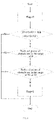
- FIG. 1 is a schematic diagram of a path, an obstacles and a vehicle
- FIG. 2 is a schematic diagram of a first parameter of an obstacle collision detection in a circular arc path
- FIG. 3 is a schematic diagram of a second parameter of an obstacle collision detection in a circular arc path
- FIG. 4 is a schematic flow chart of specific steps of a method for detecting obstacle collision in an automatic parking path according to the present application
- FIG. 5 is a schematic flow chart for determining whether a line segment of an obstacle intersects with a circular arc path contour
- FIG. 6 is a schematic diagram for determining whether an intersection point is on the line segment
- FIG. 7 is a first determination schematic diagram of whether the intersection point is on a circular arc segment
- FIG. 8 is a second determination schematic diagram of whether the intersection point is on the circular arc segment
- FIG. 9 is a schematic flow chart for determining whether a line segment of an obstacle is located in the circular arc path contour
- FIG. 10 is a parameter schematic diagram for determining whether a line segment of an obstacle is located in the circular arc path contour
- FIG. 11 is a schematic diagram for determining whether the point is within a sector range
- FIG. 12 is a schematic diagram for determining whether the line segment intersects with a vehicle contour
- FIG. 13 is a schematic diagram for determining whether the line segment is located in the vehicle contour
- FIG. 14 is a parameter schematic diagram of obstacle collision detection in a straight path.
- FIG. 15 is a schematic diagram of an obstacle path distribution.
- a method for detecting obstacle collision in an automatic parking path includes the following steps:
- the path contour is a boundary contour formed by a vehicle traveling along the path from a start point pose to an end point pose
- the path contour includes a circular arc path contour and/or a straight line path contour
- the vehicle contour is a polygon
- the obstacle contour is a line segment.
- the step of geometrically performing an obstacle collision detection in a circular arc path and/or an obstacle collision detection in a straight line path by using a path contour, a vehicle contour and an obstacle contour includes the following sub-steps:
- the obvious non-collision condition includes any one of the following conditions:
- distances between both end points of the line segment of the obstacle and a center of a circle corresponding to the circular arc path contour are all less than a first radius, the first radius being a radius corresponding to an inside circular arc segment in the circular arc path contour;
- the minimum distance from the center of the circle corresponding to the circular arc path contour to the line segment of the obstacle is greater than a second radius, the second radius being a radius corresponding to an outside circular arc segment in the circular arc path contour;
- both end points of the line segment of the obstacle are within a range of a fourth central angle, the fourth central angle being a group angle of the central angle corresponding to a planned path.
- the step of determining whether the line segment of the obstacle intersects with the circular arc path contour includes the following sub-steps:
- the straight line equation refers to a straight line equation where the line segment of the obstacle is located
- the circle equation includes a first circle equation where the inside circular arc segment in the circular arc path contour is located and a second circle equation where the outside circular arc segment in the circular arc path contour is located;
- the step of determining whether the line segment of the obstacle is located in the circular arc path contour includes the following sub-steps:
- the first region refers to a region that is within the circular ring segment of the circular arc path and does not belong to a region where the path interferes with the vehicle contour.
- the step of determining whether the line segment of the obstacle is located in a circular ring segment of the circular arc path includes the following sub-steps:
- the step of determining whether the line segment of the obstacle intersects with an end point vehicle contour includes the following sub-steps:
- the step of determining whether the line segment of the obstacle is located in the end point vehicle contour includes the following sub-steps:
- the step of geometrically performing an obstacle collision detection in a straight line path includes the following sub-steps:
- An apparatus of combining software and hardware corresponding to the above method i.e., an apparatus for detecting obstacle collision in an automatic parking path, includes:
- a memory for storing various programs
- the path contour is a boundary contour formed by a vehicle traveling along the path from a start point pose to an end point pose
- the path contour includes a circular arc path contour and/or a straight line path contour
- the vehicle contour is a polygon
- the obstacle contour is a line segment.
- a soft system corresponding to the above system i.e., a system for detecting obstacle collision in an automatic parking path, includes:
- a collision detection module configured to geometrically perform an obstacle collision detection in a circular arc path and/or an obstacle collision detection in a straight line path by using a path contour, a vehicle contour and an obstacle contour;
- the path contour is a boundary contour formed by a vehicle traveling along the path from a start point pose to an end point pose
- the path contour includes a circular arc path contour and/or a straight line path contour
- the vehicle contour is a polygon
- the obstacle contour is a line segment.
- Embodiments 1-3 are further described in combination with the contents of the present embodiment (that is, the contents of the present embodiment are applicable to the above Embodiments 1-3).
- the present application relates to a method for detecting obstacle collision in an automatic parking path, which is applicable to the parking path planning technology.
- the specific steps are as follows.
- a first step S 1 representations of path, vehicle and obstacle.
- any one of paths traj can be expressed by five parameters (x z , y z , ⁇ z , ds, ⁇ ).
- (x s , y s , ⁇ s ) is a vehicle start point pose corresponding to the path
- x z and y z are expressed as X coordinate and Y coordinate of the vehicle start point pose respectively
- ⁇ s is a heading angle of the vehicle start point pose
- ds is a length of the path, and when ds is positive, it means the vehicle moves forward; when it is negative, it means the vehicle moves backward
- any one of obstacles obj is represented by a line segment, which is described by two end points A(x 1 ,y 1 ) and B(x 2 ,y 2 ), that is, the obstacle contour is a line segment, that is, the line segment for representing the obstacle is an obstacle line segment; in the collision detection process, the vehicle contour is optimally simplified as a rectangle, and its specific parameters include three parameters as follows: vehicle length len, vehicle width width and rear suspension length h; the concept of path contour is used to detect the obstacle collision, that is, the boundary contour formed by the vehicle traveling from the start point pose to the end point pose along the path is regarded as a whole path contour, and the path obstacle collision detection is performed by a geometric method.
- the above boundary contour can be simplified as a rectangle and a circular arc segment, that is, the path contour includes a circular arc path contour and/or a straight line path contour. It can be seen that the path obstacle collision detection problem of the present application is simplified as an interference problem (intersection problem) among the rectangle, the arc-segment and the line segment.
- the vehicle contour is preferably represented by four parameters, len, width, h and swell.
- the obstacle collision detection is divided into circular arc-path obstacle collision detection and straight line-path obstacle collision detection, which use different detection methods.
- the central angle of each path in the engineering application is set to meet the condition as follows:
- ⁇ 0 first central angle
- ⁇ 1 second central angle
- ⁇ 1 second central angle
- the second central angle is formed by a center of a circle, the lower left corner point S v2 of the start point vehicle contour S v and the inside rear wheel point Ts 1 of the start point vehicle contour S v ;
- ⁇ 3 (third central angle) is a central angle corresponding to a distance between upper left corner point E v1 and the inside rear wheel point Te 1 of the end point vehicle contour E v , i.e. the third central angle is formed by a center of a circle, the inside rear wheel point Te 1 of the end point vehicle contour E v and upper left corner point E v1 of the end point vehicle contour E v .
- the center of the circle refers to a center of a circle corresponding to the planned parking path;
- the start point vehicle contour S v it refers to a vehicle contour at the start point pose;
- the end point vehicle contour E v it refers to a vehicle contour at the end point pose;
- the inside path generated by traveling of the inside rear wheel of the vehicle when the vehicle travels from the start point pose to the end point pose along the path, when the path contour is a circular arc path contour, the inside path is essentially a circular arc segment, that is, an inside circular arc segment;
- the path contour is a straight line path contour, the inside path is essentially a line segment;
- a path passed by the upper right corner point of the vehicle contour is regarded as an outside path, and when the path contour is a circular arc path contour, the outside path is essentially a circular arc segment,
- a second step S 2 an obstacle collision detection process in the circular arc path and an obstacle collision detection process in the straight line path.
- steps of the obstacle collision detection process in the automatic parking path of the present application as shown in FIG. 4 , they specifically include:
- collision mark flag_cross 1
- the collision flag flag_cross 0.
- condition 1 distances between two end points A and B of the obstacle line segment and the center O of the circle corresponding to the circular arc path contour are smaller than a first radius R 1 , where the first radius R 1 is a radius corresponding to the inside circular arc segment in the circular arc path contour;
- condition 2 the minimum distance from the center O of the circle corresponding to the circular arc path contour to the obstacle line segment AB is greater than the second radius R 2 , where the second radius R 2 is a radius corresponding to the outside circular arc segment of the circular arc path contour; the minimum distance refers to the smaller of the distances from the center O to both end points A and B of the obstacle line segment;
- both end points A and B of the obstacle line segment are located within a range of a fourth central angle ⁇ S v2 OE v1
- the fourth central angle is a group angle of a central angle ⁇ corresponding to the planned path
- the group angle refers to an angle that is equal to 360 degrees when the central angle ⁇ is added.
- a subsequent collision detection process is not needed. That is to say, when the obstacle meets the obvious non-collision condition, it is determined that the obstacle does not collide with the path, and the collision detection is ended, and the subsequent collision detection process is not needed.
- this embodiment uses vector cross product to determine whether two end points A and B of the obstacle line segment are both located in the range of ⁇ S v2 OE v1 .
- the step of determining whether the obstacle meets the obvious non-collision condition includes a sub-step of using vector cross product to determine whether the two end points A and B of the obstacle line segment are both located in the range of ⁇ S v2 OE v1 .
- the sub-step includes specific calculation steps as follows:
- This step includes the following sub-steps.
- the circle includes a first circle where the inside circular arc segment in the circular arc path contour is located, and a second circle where the outside circular arc segment in the circular arc path contour is located, that is, the circle equation includes a first circle equation (inside circle equation) corresponding to the circle (the first circle) where the inside circular arc segment in the circular arc path contour is located, and the second circle equation (outside circle equation) corresponding to the circle (the second circle) where the outside circular arc segment in the circular arc path contour is located, where:
- (x c , y c ) is the coordinate of the center O of the circle.
- step S 201 specifically includes the following sub-steps:
- a 1 + A 2 B 2
- b 2 ⁇ A ⁇ ⁇ C B 2 + D - AE B
- c C 2 B 2 - CE B + F ;
- This determination is to determine whether the intersection point P is on the obstacle line segment. First, it can be ensured that the intersection point P is definitely on the straight line. As shown in FIG. 6 , when the intersection point P is on the obstacle line segment AB, it meets: ⁇ right arrow over (PA) ⁇ right arrow over (PB) ⁇ 0; otherwise, the intersection point P is on an extension line of the obstacle line segment AB.
- determining whether the dot product ⁇ right arrow over (PA) ⁇ right arrow over (PB) ⁇ of the two vectors is less than 0, and if it is yes, it means that the calculated intersection point P is on the obstacle line segment AB; otherwise, it means that the calculated intersection point P is on the extension line of the obstacle line segment AB, that is, there is no interference (no intersection) between the obstacle line segment and the circular arc path contour.
- Case 1 (as shown in FIG. 7 ): ⁇ (here, ⁇ represents degrees of the central angle corresponding to the inside/outside circular arc segment in the circular arc path contour). If the calculated intersection point P and the center O of the circle are located on both sides of a first line segment AB respectively (here, the first line segment AB refers to a line segment composed of two end points of the circular arc segment), then the intersection point P is located on the circular arc segment, that is, an interference (intersection) occurs between the obstacle line segment and the circular arc path contour; otherwise, it means that the calculated intersection point P is located on the extension line of the circular arc segment, that is, no interference (no intersection) occurs between the obstacle line segment and the circular arc path contour.
- ⁇ here, ⁇ represents degrees of the central angle corresponding to the inside/outside circular arc segment in the circular arc path contour.
- Case 2 (as shown in FIG. 8 ): ⁇ (here, ⁇ represents degrees of the central angle corresponding to the inside/outside circular arc segment in the circular arc path contour). If the calculated intersection point P and the center O of the circle are located on the same side of the first line segment AB (here, the first line segment AB refers to a line segment composed of two end points of the circular arc segment), then the intersection point P is located on the circular arc segment, that is, an interference (intersection) occurs between the obstacle line segment and the circular arc path contour; otherwise, it means that the calculated intersection point P is located on the extension line of the circular arc segment, that is, no interference (no intersection) occurs between the obstacle line segment and the circular arc path contour.
- ⁇ here, ⁇ represents degrees of the central angle corresponding to the inside/outside circular arc segment in the circular arc path contour.
- this embodiment determines whether the intersection point P and the center O are on the same side of the first line segment AB by positive or negative of the component Z of cross product result of the vectors, and this step specifically includes:
- the circular ring segment of the circular arc path refers to a sector ring corresponding to the fifth central angle ⁇ , that is to say, the circular ring segment is a part of the circle cut out by a sector corresponding to the fifth central angle, where the fifth central angle ⁇ refers to a central angle formed by the center O of the circle, the inside rear wheel point Ts 1 of the start point vehicle contour S v and the upper right corner point E v4 of the end point vehicle contour E v , and a path is included within a range of the fifth central angle ⁇ ; the circular ring is obtained by subtracting the first circle from the second circle.
- the circular ring segment it is obtained by cutting the circular ring via a second line segment and a third line segment, and an arc line segment of the circular ring segment covers the inside circular arc segment and the outside circular arc segment of the path contour;
- the second line segment is formed by a second end point P se and the inside rear wheel point Ts 1 of the start point vehicle contour S v
- the second end point P se refers to an intersection point between an extension line of a line connecting the point Ts 1 with the center O and the second circle
- the third line segment is formed by a third end point and the upper right corner point E v4 of the end point vehicle contour E v
- the third end point refers to an intersection point between a line connecting the point E v4 with the center O and the first circle.
- step S 301 specifically includes the following sub-steps:
- step S 3012 as shown in FIG. 11 , specific implementation steps are as follows:
- step S 403 it specifically includes the following sub-steps:
- step S 404 it specifically includes the following sub-steps:
- intersection determination criterion x c ⁇ 0 and x c ⁇ dis_obs, that is, when x c ⁇ 0 and x c ⁇ dis_obs are determined, it means that the obstacle line segment intersects with the rectangular contour of the end point vehicle contour.
- dis_obs represents a length of the obstacle line segment.
- step S 501 it includes the following sub-steps:
- the above calculation and determination can be made on the other end point B of the obstacle line segment (i.e., replace the above end point A with the end point B), so as to determine whether the other end point B of the obstacle line segment is within the end point vehicle contour;
- both end points A and B of the obstacle line segment are located in the end point vehicle contour, it means that the obstacle line segment is located in the end point vehicle contour; otherwise, the obstacle line segment is not located in the end point vehicle contour.
- P 1 , P 2 , P 3 and P 4 are the upper left corner point, lower left corner point, lower right corner point and upper right corner point of the end point vehicle contour, respectively.
- the vehicle traveling contour is simplified as a rectangle P 1 P 2 P 3 P 4 , that is, the straight line path contour, and then the collision determination is performed according to the interference determination method between the obstacle line segment and the rectangular contour, so as to realize the collision detection.
- step of geometrically performing an obstacle collision detection in a straight line path includes the following sub-steps:
- determining whether the obstacle collides with the path according to a determined result specifically:
- FIG. 15 is a schematic diagram of a path distribution of obstacles.
Landscapes
- Engineering & Computer Science (AREA)
- Automation & Control Theory (AREA)
- Radar, Positioning & Navigation (AREA)
- Remote Sensing (AREA)
- Transportation (AREA)
- Mechanical Engineering (AREA)
- Physics & Mathematics (AREA)
- General Physics & Mathematics (AREA)
- Aviation & Aerospace Engineering (AREA)
- Mathematical Physics (AREA)
- Chemical & Material Sciences (AREA)
- Combustion & Propulsion (AREA)
- Human Computer Interaction (AREA)
- Traffic Control Systems (AREA)
- Image Analysis (AREA)
Abstract
Description
Where θ(θ=θ0+θ1+θ2) represents a central angle corresponding to a planned parking path, referred to as the central angle corresponding to the planned path; θ0 (first central angle) is a central angle corresponding to an inside path generated by traveling of the inside rear wheel (left rear wheel) of the vehicle when the vehicle travels from the start point pose to the end point pose along the path, that is, the first central angle is formed by a center of a circle, inside rear wheel point Ts1 of a start point vehicle contour Sv, and inside rear wheel point Te1 of an end point vehicle contour Ev, and the central angle is the turning angle of the vehicle; θ1 (second central angle) is a central angle corresponding to a distance between lower left corner point Sv2 and the inside rear wheel point Ts1 of the start point vehicle contour Sv, i.e. the second central angle is formed by a center of a circle, the lower left corner point Sv2 of the start point vehicle contour Sv and the inside rear wheel point Ts1 of the start point vehicle contour Sv; θ3 (third central angle) is a central angle corresponding to a distance between upper left corner point Ev1 and the inside rear wheel point Te1 of the end point vehicle contour Ev, i.e. the third central angle is formed by a center of a circle, the inside rear wheel point Te1 of the end point vehicle contour Ev and upper left corner point Ev1 of the end point vehicle contour Ev.
if Δ<0, then the above quadratic equation has no real root, that is, there is no intersection point between the circle and the straight line;
if Δ<0, then the above quadratic equation has no real root, that is, there is no intersection point between the circle and the straight line.
| TABLE 1 | ||||
| Consumed | ||||
| time by the | ||||
| present | Consumed time | |||
| Number | application | by traversal | Consumed | |
| Serial | of | method | method | time ratio |
| number | obstacles | t1 (ms) | t2 (ms) | (t2/t1) |
| 1 | 5 | 189 | 1904 | 10.07 |
| 2 | 10 | 348 | 3275 | 9.41 |
| 3 | 15 | 480 | 4691 | 9.77 |
| 4 | 20 | 611 | 6140 | 10.04 |
| 5 | 25 | 819 | 7691 | 9.39 |
| 6 | 30 | 1053 | 9177 | 8.71 |
Claims (8)
Applications Claiming Priority (3)
| Application Number | Priority Date | Filing Date | Title |
|---|---|---|---|
| CN201710755754.1A CN107672588B (en) | 2017-08-29 | 2017-08-29 | An automatic parking path obstacle collision detection method, device and system |
| CN201710755754.1 | 2017-08-29 | ||
| PCT/CN2018/102812 WO2019042296A1 (en) | 2017-08-29 | 2018-08-29 | Method, apparatus and system for detecting obstacle collision in automatic parking path |
Related Parent Applications (1)
| Application Number | Title | Priority Date | Filing Date |
|---|---|---|---|
| PCT/CN2018/102812 Continuation WO2019042296A1 (en) | 2017-08-29 | 2018-08-29 | Method, apparatus and system for detecting obstacle collision in automatic parking path |
Publications (2)
| Publication Number | Publication Date |
|---|---|
| US20200130696A1 US20200130696A1 (en) | 2020-04-30 |
| US11433899B2 true US11433899B2 (en) | 2022-09-06 |
Family
ID=61134774
Family Applications (1)
| Application Number | Title | Priority Date | Filing Date |
|---|---|---|---|
| US16/732,249 Active 2039-06-06 US11433899B2 (en) | 2017-08-29 | 2019-12-31 | Method, apparatus and system for detecting obstacle collision in automatic parking path |
Country Status (3)
| Country | Link |
|---|---|
| US (1) | US11433899B2 (en) |
| CN (1) | CN107672588B (en) |
| WO (1) | WO2019042296A1 (en) |
Families Citing this family (43)
| Publication number | Priority date | Publication date | Assignee | Title |
|---|---|---|---|---|
| CN107672588B (en) | 2017-08-29 | 2020-05-08 | 广州小鹏汽车科技有限公司 | An automatic parking path obstacle collision detection method, device and system |
| CN110647141B (en) * | 2018-06-27 | 2022-11-08 | 西安合众思壮导航技术有限公司 | Method, device and system for generating obstacle avoidance path |
| US11183059B2 (en) * | 2019-04-22 | 2021-11-23 | Baidu Usa Llc | Parking management architecture for parking autonomous driving vehicles |
| CN112097781B (en) * | 2019-06-17 | 2023-05-09 | 宇通客车股份有限公司 | Path planning method and device based on multistage tentacles |
| CN110334448B (en) * | 2019-07-08 | 2023-01-24 | 中国建筑第八工程局有限公司 | Collision detection method and system for mechanical parking space |
| CN110471421B (en) * | 2019-08-27 | 2022-03-18 | 广州小鹏汽车科技有限公司 | Path planning method and path planning system for safe driving of vehicles |
| CN113119964B (en) * | 2019-12-30 | 2022-08-02 | 宇通客车股份有限公司 | Collision prediction judgment method and device for automatic driving vehicle |
| CN111114542B (en) * | 2020-02-19 | 2021-07-02 | 北京百度网讯科技有限公司 | Curve driving control method, device, device and medium for autonomous vehicle |
| CN111309013B (en) * | 2020-02-24 | 2022-12-13 | 广州小鹏汽车科技有限公司 | A collision distance determination method and system, vehicle, and storage medium |
| US11498554B2 (en) | 2020-02-25 | 2022-11-15 | Ford Global Technologies, Llc | Enhanced object detection and response |
| CN111591307B (en) * | 2020-04-15 | 2021-10-01 | 毫末智行科技有限公司 | Obstacle avoidance track planning method and system and vehicle |
| CN111674390B (en) * | 2020-05-09 | 2021-07-02 | 惠州市德赛西威汽车电子股份有限公司 | Obstacle avoidance method for automatic parking path planning and parking path planning system |
| CN111708365A (en) * | 2020-06-24 | 2020-09-25 | 宝武集团环境资源科技有限公司 | Automatic path planning method |
| CN112269965B (en) * | 2020-08-10 | 2024-04-05 | 中国北方车辆研究所 | Continuous curvature path optimization method under incomplete constraint condition |
| CN112036385B (en) * | 2020-11-04 | 2021-02-02 | 天津天瞳威势电子科技有限公司 | Library position correction method and device, electronic equipment and readable storage medium |
| CN112729320B (en) * | 2020-12-22 | 2022-05-17 | 中国第一汽车股份有限公司 | Method, device and equipment for constructing obstacle map and storage medium |
| CN112904851B (en) * | 2021-01-18 | 2024-07-23 | 广州小鹏自动驾驶科技有限公司 | Obstacle position correction method, system, computer equipment and storage medium |
| KR20220136679A (en) * | 2021-04-01 | 2022-10-11 | 현대자동차주식회사 | Apparatus and method for controlling driving of vehicle |
| DE102021109661B4 (en) * | 2021-04-16 | 2023-03-09 | Avl Software And Functions Gmbh | Method for the geometric representation of a vehicle surface of a vehicle for collision detection |
| CN113252040B (en) * | 2021-05-08 | 2022-10-18 | 云南财经大学 | Improved AGV trolley two-dimensional code arc navigation method |
| US12099371B2 (en) * | 2021-06-04 | 2024-09-24 | Ubkang (Qingdao) Technology Co., Ltd. | Fast continuous regulation of nonholonomic mobile robots |
| CN113269372B (en) * | 2021-06-23 | 2024-08-23 | 华北电力大学 | A method for predicting and evaluating the dispatchable capacity of cluster electric vehicles considering user willingness |
| CN113548406B (en) * | 2021-08-12 | 2022-04-22 | 广东顺力智能物流装备股份有限公司 | Contour scanning laser navigation unmanned car for intelligent logistics and its use method |
| CN113670632B (en) * | 2021-08-18 | 2024-04-12 | 北京经纬恒润科技股份有限公司 | Collision detection method and device |
| CN113771850A (en) * | 2021-09-08 | 2021-12-10 | 恒大新能源汽车投资控股集团有限公司 | Vehicle road running control method and device and computer readable storage medium |
| CN113978455B (en) * | 2021-09-26 | 2024-06-07 | 惠州市德赛西威汽车电子股份有限公司 | Method and system for constructing driving track auxiliary line |
| CN115080018A (en) * | 2022-02-15 | 2022-09-20 | 安徽域驰智能科技有限公司 | Automatic parking off-line analysis system based on LabVIEW programming |
| CN114701485A (en) * | 2022-03-28 | 2022-07-05 | 华人运通(上海)自动驾驶科技有限公司 | Safe path planning method in field, automatic parking method and storage medium |
| CN114889585B (en) * | 2022-05-26 | 2024-07-23 | 重庆长安汽车股份有限公司 | Path planning method for remote curve vehicle moving |
| CN114834447B (en) * | 2022-05-30 | 2023-01-20 | 远峰科技股份有限公司 | Collision risk prediction method and device based on automatic parking trajectory |
| CN115237124B (en) * | 2022-06-30 | 2025-11-25 | 魔门塔(苏州)科技有限公司 | Methods and devices for determining travel path boundaries, vehicles, storage media, and terminals |
| CN115285113A (en) * | 2022-08-30 | 2022-11-04 | 重庆长安汽车股份有限公司 | A kind of automatic parking method and device, equipment and medium |
| CN115291611B (en) * | 2022-08-31 | 2026-03-03 | 河南科技大学 | Unmanned vehicle path planning method and system |
| CN115933650B (en) * | 2022-11-24 | 2026-04-14 | 北京京东乾石科技有限公司 | Vehicle control method, device, equipment and storage medium |
| CN115655261B (en) * | 2022-12-09 | 2023-04-07 | 深圳鹏行智能研究有限公司 | Map generation method, map generation device, robot, and storage medium |
| DE102022213587A1 (en) * | 2022-12-14 | 2024-06-20 | Continental Autonomous Mobility Germany GmbH | Method for determining a driving path along a planned driving trajectory, control device, vehicle and computer program |
| CN116215517B (en) * | 2023-01-30 | 2026-01-02 | 北京百度网讯科技有限公司 | Collision detection methods, devices, equipment, storage media, and autonomous vehicles |
| CN115973196B (en) * | 2023-03-16 | 2023-06-16 | 中国科学院大学 | Anti-collision method, device and system for special-shaped ring of mining unmanned vehicle |
| CN116562027B (en) * | 2023-05-12 | 2023-11-28 | 江苏大学 | Two-dimensional continuous collision detection method for circle and line segment set |
| CN119953351B (en) * | 2023-11-07 | 2025-11-18 | 魔门塔(苏州)科技有限公司 | Parking control method and device, electronic equipment and medium |
| KR20250097558A (en) * | 2023-12-21 | 2025-06-30 | 현대자동차주식회사 | Method And Apparatus for Generating Memory Parking Path |
| CN121459317A (en) * | 2024-08-01 | 2026-02-03 | 纬创资通股份有限公司 | Identification method and system for fusion parking space information |
| CN119705436B (en) * | 2025-01-20 | 2025-10-24 | 重庆长安汽车股份有限公司 | Obstacle collision distance determination method, device, equipment and storage medium |
Citations (10)
| Publication number | Priority date | Publication date | Assignee | Title |
|---|---|---|---|---|
| IT1138212B (en) | 1981-09-09 | 1986-09-17 | Lajos Siegriszt | Trellis using prefabricated beams |
| WO2005085043A1 (en) | 2004-03-05 | 2005-09-15 | Continental Teves Ag & Co.Ohg | Parking aid |
| US20120303258A1 (en) | 2009-10-02 | 2012-11-29 | Christian Pampus | Method for mapping the surroundings of a vehicle |
| CN102963358A (en) | 2011-08-31 | 2013-03-13 | 通用汽车环球科技运作有限责任公司 | System and method for collision avoidance maneuver path determination with jerk limit |
| CN104354656A (en) | 2014-10-20 | 2015-02-18 | 同济大学 | Obstacle detection and garage position distinguishing method of intelligent parking system and implement system thereof |
| US20160075329A1 (en) * | 2014-09-12 | 2016-03-17 | Toyota Jidosha Kabushiki Kaisha | Parking assist system and path determination method |
| CN106114511A (en) | 2016-07-21 | 2016-11-16 | 辽宁工业大学 | A kind of automobile cruise system core target identification method |
| CN106874551A (en) | 2017-01-11 | 2017-06-20 | 成都信息工程大学 | A kind of Parallel parking method for being based on three rank arctan function models |
| CN106945662A (en) | 2017-03-30 | 2017-07-14 | 重庆大学 | A kind of vertical automatic parking paths planning method and system |
| CN107672588A (en) | 2017-08-29 | 2018-02-09 | 广州小鹏汽车科技有限公司 | A kind of automatic parking path obstructions collision checking method, apparatus and system |
-
2017
- 2017-08-29 CN CN201710755754.1A patent/CN107672588B/en active Active
-
2018
- 2018-08-29 WO PCT/CN2018/102812 patent/WO2019042296A1/en not_active Ceased
-
2019
- 2019-12-31 US US16/732,249 patent/US11433899B2/en active Active
Patent Citations (10)
| Publication number | Priority date | Publication date | Assignee | Title |
|---|---|---|---|---|
| IT1138212B (en) | 1981-09-09 | 1986-09-17 | Lajos Siegriszt | Trellis using prefabricated beams |
| WO2005085043A1 (en) | 2004-03-05 | 2005-09-15 | Continental Teves Ag & Co.Ohg | Parking aid |
| US20120303258A1 (en) | 2009-10-02 | 2012-11-29 | Christian Pampus | Method for mapping the surroundings of a vehicle |
| CN102963358A (en) | 2011-08-31 | 2013-03-13 | 通用汽车环球科技运作有限责任公司 | System and method for collision avoidance maneuver path determination with jerk limit |
| US20160075329A1 (en) * | 2014-09-12 | 2016-03-17 | Toyota Jidosha Kabushiki Kaisha | Parking assist system and path determination method |
| CN104354656A (en) | 2014-10-20 | 2015-02-18 | 同济大学 | Obstacle detection and garage position distinguishing method of intelligent parking system and implement system thereof |
| CN106114511A (en) | 2016-07-21 | 2016-11-16 | 辽宁工业大学 | A kind of automobile cruise system core target identification method |
| CN106874551A (en) | 2017-01-11 | 2017-06-20 | 成都信息工程大学 | A kind of Parallel parking method for being based on three rank arctan function models |
| CN106945662A (en) | 2017-03-30 | 2017-07-14 | 重庆大学 | A kind of vertical automatic parking paths planning method and system |
| CN107672588A (en) | 2017-08-29 | 2018-02-09 | 广州小鹏汽车科技有限公司 | A kind of automatic parking path obstructions collision checking method, apparatus and system |
Non-Patent Citations (3)
| Title |
|---|
| The Chinese Examination Report and Search Report of corresponding Chinese application No. 201710755754.1, dated Mar. 13, 2019. |
| The International Search Report of corresponding International application No. PCT/CN2018/02812, dated Nov. 16, 2018. |
| Vorobieva, Hélène, et al. "Automatic parallel parking in tiny spots: Path planning and control." IEEE Transactions on Intelligent Transportation Systems 16.1 (2014): 396-410. (Year: 2014). * |
Also Published As
| Publication number | Publication date |
|---|---|
| CN107672588B (en) | 2020-05-08 |
| US20200130696A1 (en) | 2020-04-30 |
| CN107672588A (en) | 2018-02-09 |
| WO2019042296A1 (en) | 2019-03-07 |
Similar Documents
| Publication | Publication Date | Title |
|---|---|---|
| US11433899B2 (en) | Method, apparatus and system for detecting obstacle collision in automatic parking path | |
| US12391242B2 (en) | Method and apparatus for determining travel path bound, vehicle, storage medium, and terminal | |
| CN111830979B (en) | Track optimization method and device | |
| CN113296119B (en) | Unmanned obstacle avoidance driving method and terminal based on laser radar and UWB array | |
| US10838424B2 (en) | Charging station identifying method and robot | |
| US12045057B2 (en) | Turning control method for construction machine, construction machine and computer device | |
| CN113721608B (en) | Robot local path planning method, system and readable storage medium | |
| CN106932805A (en) | It is a kind of to be suitable to the swift electron fence method of mobile device application | |
| US12509076B2 (en) | Vehicle control method and apparatus, electronic device, and storage medium | |
| CN114310893B (en) | Robot driving control method, device, equipment and storage medium | |
| CN117091615A (en) | Path planning method, path planning device, vehicle and storage medium | |
| CN114967710A (en) | Automatic driving obstacle avoidance path planning system and method based on control point fitting polynomial | |
| CN110815202A (en) | Obstacle detection method and device | |
| CN116661454A (en) | Robot control method, device, electronic device and storage medium | |
| CN114115291A (en) | Vehicle path planning method under complex non-convex environment | |
| CN115837921B (en) | Vehicle track collision detection method, device, equipment and storage medium | |
| CN115352437A (en) | Automatic parking path planning method and device and self-moving equipment | |
| CN113670632B (en) | Collision detection method and device | |
| CN115407774B (en) | Driving route planning methods and devices, vehicles, storage media, and terminals | |
| Wang et al. | SS-RRT*: A safe and smoothing path planner for mobile robot in static environment | |
| CN113138594A (en) | Automatic driving method and device | |
| CN116203974A (en) | Method and device for controlling mobile robot to be in butt joint with equipment | |
| CN117420819A (en) | Global path planning method and device, mobile tool and storage medium | |
| CN116215512A (en) | Processing method and device, storage medium, and terminal for vehicle collision detection | |
| CN116125981B (en) | Methods, apparatus, systems, devices, and storage media for optimizing cluster formation structure |
Legal Events
| Date | Code | Title | Description |
|---|---|---|---|
| AS | Assignment |
Owner name: GUANGZHOU XIAOPENG MOTORS TECHNOLOGY CO., LTD., CHINA Free format text: ASSIGNMENT OF ASSIGNORS INTEREST;ASSIGNORS:XIAO, ZHIGUANG;LAI, JIANMING;TU, QIANG;AND OTHERS;REEL/FRAME:051395/0704 Effective date: 20191226 |
|
| FEPP | Fee payment procedure |
Free format text: ENTITY STATUS SET TO UNDISCOUNTED (ORIGINAL EVENT CODE: BIG.); ENTITY STATUS OF PATENT OWNER: LARGE ENTITY |
|
| STPP | Information on status: patent application and granting procedure in general |
Free format text: DOCKETED NEW CASE - READY FOR EXAMINATION |
|
| STPP | Information on status: patent application and granting procedure in general |
Free format text: NON FINAL ACTION MAILED |
|
| STPP | Information on status: patent application and granting procedure in general |
Free format text: RESPONSE TO NON-FINAL OFFICE ACTION ENTERED AND FORWARDED TO EXAMINER |
|
| STPP | Information on status: patent application and granting procedure in general |
Free format text: NOTICE OF ALLOWANCE MAILED -- APPLICATION RECEIVED IN OFFICE OF PUBLICATIONS |
|
| STPP | Information on status: patent application and granting procedure in general |
Free format text: PUBLICATIONS -- ISSUE FEE PAYMENT VERIFIED |
|
| STCF | Information on status: patent grant |
Free format text: PATENTED CASE |
|
| MAFP | Maintenance fee payment |
Free format text: PAYMENT OF MAINTENANCE FEE, 4TH YEAR, LARGE ENTITY (ORIGINAL EVENT CODE: M1551); ENTITY STATUS OF PATENT OWNER: LARGE ENTITY Year of fee payment: 4 |