US11433727B2 - Electric suspension device - Google Patents
Electric suspension device Download PDFInfo
- Publication number
- US11433727B2 US11433727B2 US17/199,799 US202117199799A US11433727B2 US 11433727 B2 US11433727 B2 US 11433727B2 US 202117199799 A US202117199799 A US 202117199799A US 11433727 B2 US11433727 B2 US 11433727B2
- Authority
- US
- United States
- Prior art keywords
- sprung
- speed
- bounce
- sprung speed
- dead zone
- Prior art date
- Legal status (The legal status is an assumption and is not a legal conclusion. Google has not performed a legal analysis and makes no representation as to the accuracy of the status listed.)
- Active
Links
Images




Classifications
-
- B—PERFORMING OPERATIONS; TRANSPORTING
- B60—VEHICLES IN GENERAL
- B60G—VEHICLE SUSPENSION ARRANGEMENTS
- B60G17/00—Resilient suspensions having means for adjusting the spring or vibration-damper characteristics, for regulating the distance between a supporting surface and a sprung part of vehicle or for locking suspension during use to meet varying vehicular or surface conditions, e.g. due to speed or load
- B60G17/015—Resilient suspensions having means for adjusting the spring or vibration-damper characteristics, for regulating the distance between a supporting surface and a sprung part of vehicle or for locking suspension during use to meet varying vehicular or surface conditions, e.g. due to speed or load the regulating means comprising electric or electronic elements
- B60G17/0152—Resilient suspensions having means for adjusting the spring or vibration-damper characteristics, for regulating the distance between a supporting surface and a sprung part of vehicle or for locking suspension during use to meet varying vehicular or surface conditions, e.g. due to speed or load the regulating means comprising electric or electronic elements characterised by the action on a particular type of suspension unit
- B60G17/0157—Resilient suspensions having means for adjusting the spring or vibration-damper characteristics, for regulating the distance between a supporting surface and a sprung part of vehicle or for locking suspension during use to meet varying vehicular or surface conditions, e.g. due to speed or load the regulating means comprising electric or electronic elements characterised by the action on a particular type of suspension unit non-fluid unit, e.g. electric motor
-
- B—PERFORMING OPERATIONS; TRANSPORTING
- B60—VEHICLES IN GENERAL
- B60G—VEHICLE SUSPENSION ARRANGEMENTS
- B60G17/00—Resilient suspensions having means for adjusting the spring or vibration-damper characteristics, for regulating the distance between a supporting surface and a sprung part of vehicle or for locking suspension during use to meet varying vehicular or surface conditions, e.g. due to speed or load
- B60G17/015—Resilient suspensions having means for adjusting the spring or vibration-damper characteristics, for regulating the distance between a supporting surface and a sprung part of vehicle or for locking suspension during use to meet varying vehicular or surface conditions, e.g. due to speed or load the regulating means comprising electric or electronic elements
-
- B—PERFORMING OPERATIONS; TRANSPORTING
- B60—VEHICLES IN GENERAL
- B60G—VEHICLE SUSPENSION ARRANGEMENTS
- B60G17/00—Resilient suspensions having means for adjusting the spring or vibration-damper characteristics, for regulating the distance between a supporting surface and a sprung part of vehicle or for locking suspension during use to meet varying vehicular or surface conditions, e.g. due to speed or load
- B60G17/015—Resilient suspensions having means for adjusting the spring or vibration-damper characteristics, for regulating the distance between a supporting surface and a sprung part of vehicle or for locking suspension during use to meet varying vehicular or surface conditions, e.g. due to speed or load the regulating means comprising electric or electronic elements
- B60G17/016—Resilient suspensions having means for adjusting the spring or vibration-damper characteristics, for regulating the distance between a supporting surface and a sprung part of vehicle or for locking suspension during use to meet varying vehicular or surface conditions, e.g. due to speed or load the regulating means comprising electric or electronic elements characterised by their responsiveness, when the vehicle is travelling, to specific motion, a specific condition, or driver input
-
- B—PERFORMING OPERATIONS; TRANSPORTING
- B60—VEHICLES IN GENERAL
- B60G—VEHICLE SUSPENSION ARRANGEMENTS
- B60G17/00—Resilient suspensions having means for adjusting the spring or vibration-damper characteristics, for regulating the distance between a supporting surface and a sprung part of vehicle or for locking suspension during use to meet varying vehicular or surface conditions, e.g. due to speed or load
- B60G17/015—Resilient suspensions having means for adjusting the spring or vibration-damper characteristics, for regulating the distance between a supporting surface and a sprung part of vehicle or for locking suspension during use to meet varying vehicular or surface conditions, e.g. due to speed or load the regulating means comprising electric or electronic elements
- B60G17/018—Resilient suspensions having means for adjusting the spring or vibration-damper characteristics, for regulating the distance between a supporting surface and a sprung part of vehicle or for locking suspension during use to meet varying vehicular or surface conditions, e.g. due to speed or load the regulating means comprising electric or electronic elements characterised by the use of a specific signal treatment or control method
-
- B—PERFORMING OPERATIONS; TRANSPORTING
- B60—VEHICLES IN GENERAL
- B60G—VEHICLE SUSPENSION ARRANGEMENTS
- B60G17/00—Resilient suspensions having means for adjusting the spring or vibration-damper characteristics, for regulating the distance between a supporting surface and a sprung part of vehicle or for locking suspension during use to meet varying vehicular or surface conditions, e.g. due to speed or load
- B60G17/06—Characteristics of dampers, e.g. mechanical dampers
-
- B—PERFORMING OPERATIONS; TRANSPORTING
- B60—VEHICLES IN GENERAL
- B60G—VEHICLE SUSPENSION ARRANGEMENTS
- B60G17/00—Resilient suspensions having means for adjusting the spring or vibration-damper characteristics, for regulating the distance between a supporting surface and a sprung part of vehicle or for locking suspension during use to meet varying vehicular or surface conditions, e.g. due to speed or load
- B60G17/06—Characteristics of dampers, e.g. mechanical dampers
- B60G17/08—Characteristics of fluid dampers
-
- B—PERFORMING OPERATIONS; TRANSPORTING
- B60—VEHICLES IN GENERAL
- B60G—VEHICLE SUSPENSION ARRANGEMENTS
- B60G2202/00—Indexing codes relating to the type of spring, damper or actuator
- B60G2202/40—Type of actuator
- B60G2202/42—Electric actuator
-
- B—PERFORMING OPERATIONS; TRANSPORTING
- B60—VEHICLES IN GENERAL
- B60G—VEHICLE SUSPENSION ARRANGEMENTS
- B60G2202/00—Indexing codes relating to the type of spring, damper or actuator
- B60G2202/40—Type of actuator
- B60G2202/42—Electric actuator
- B60G2202/422—Linear motor
-
- B—PERFORMING OPERATIONS; TRANSPORTING
- B60—VEHICLES IN GENERAL
- B60G—VEHICLE SUSPENSION ARRANGEMENTS
- B60G2400/00—Indexing codes relating to detected, measured or calculated conditions or factors
- B60G2400/05—Attitude
- B60G2400/052—Angular rate
- B60G2400/0521—Roll rate
-
- B—PERFORMING OPERATIONS; TRANSPORTING
- B60—VEHICLES IN GENERAL
- B60G—VEHICLE SUSPENSION ARRANGEMENTS
- B60G2400/00—Indexing codes relating to detected, measured or calculated conditions or factors
- B60G2400/10—Acceleration; Deceleration
-
- B—PERFORMING OPERATIONS; TRANSPORTING
- B60—VEHICLES IN GENERAL
- B60G—VEHICLE SUSPENSION ARRANGEMENTS
- B60G2400/00—Indexing codes relating to detected, measured or calculated conditions or factors
- B60G2400/10—Acceleration; Deceleration
- B60G2400/102—Acceleration; Deceleration vertical
-
- B—PERFORMING OPERATIONS; TRANSPORTING
- B60—VEHICLES IN GENERAL
- B60G—VEHICLE SUSPENSION ARRANGEMENTS
- B60G2400/00—Indexing codes relating to detected, measured or calculated conditions or factors
- B60G2400/20—Speed
- B60G2400/202—Piston speed; Relative velocity between vehicle body and wheel
-
- B—PERFORMING OPERATIONS; TRANSPORTING
- B60—VEHICLES IN GENERAL
- B60G—VEHICLE SUSPENSION ARRANGEMENTS
- B60G2400/00—Indexing codes relating to detected, measured or calculated conditions or factors
- B60G2400/20—Speed
- B60G2400/206—Body oscillation speed; Body vibration frequency
-
- B—PERFORMING OPERATIONS; TRANSPORTING
- B60—VEHICLES IN GENERAL
- B60G—VEHICLE SUSPENSION ARRANGEMENTS
- B60G2400/00—Indexing codes relating to detected, measured or calculated conditions or factors
- B60G2400/25—Stroke; Height; Displacement
- B60G2400/252—Stroke; Height; Displacement vertical
-
- B—PERFORMING OPERATIONS; TRANSPORTING
- B60—VEHICLES IN GENERAL
- B60G—VEHICLE SUSPENSION ARRANGEMENTS
- B60G2500/00—Indexing codes relating to the regulated action or device
- B60G2500/10—Damping action or damper
Definitions
- the present invention relates an electric suspension device including an actuator that is provided between a body and a wheel of a vehicle and generates damping force for damping vibration of the body.
- An electric suspension device which includes an actuator that is provided between a body and a wheel of a vehicle and generates damping force for damping vibration of the body (see Patent Literature 1).
- the electric suspension device disclosed in Patent Literature 1 includes: a basic input amount calculation unit that calculates a basic input amount of the vehicle based on an amount of change in wheel speed detected by a wheel speed sensor; a target current setting unit that sets a target current based on the basic input amount; a target current setting unit that sets a target current based on an acceleration of the body of the vehicle detected by an acceleration sensor; and a control unit that controls a damper (actuator) based on the target current when a vehicle behavior control device that controls behavior of the vehicle is not operating, and controls the damper based on the target current when the vehicle behavior control device is operating.
- a basic input amount calculation unit that calculates a basic input amount of the vehicle based on an amount of change in wheel speed detected by a wheel speed sensor
- a target current setting unit that sets a target current based on the basic input amount
- a target current setting unit that sets a target current based on an acceleration of the body of the vehicle detected by an acceleration sensor
- a control unit that controls a damp
- the electric suspension device disclosed in Patent Literature 1 can appropriately control the damping force of the actuator regardless of the caster angle at which the suspension is set and without using vertical G sensors or stroke sensors.
- Patent Literature 1 JP 2015-047906 A
- a damping force base value calculation unit calculates a damping force base value (in consideration of correction at a subsequent stage) by referring to a sprung speed-damping force map based on a sprung speed inputted to the damping force base value calculation unit, as illustrated and described in FIG. 12 and paragraph 0080 of Patent Literature 1.
- a dead zone in which the damping force base value is zero is set in a sprung speed including a switch point at which the direction of the sprung speed switches from the extension side to the contraction side or from the contraction side to the extension side.
- the dead zone is set in the speed rage including the switch point and a fixed value (zero) is associated as the damping force base value with the values of the sprung speed in this dead zone. In this way, even when values of the sprung speed contain errors, erroneous damping force control attributable to these errors is avoided as much as possible.
- Patent Literature 1 which performs a computation involving setting the dead zone in the speed range in which the sprung speed is at or around the switch point, and associating a fixed value (zero) as the damping force base value with the values of the sprung speed in this speed range, and controls the driving of the actuator by using the damping force base value obtained as the result of this computation, even if the values of the sprung speed in the dead zone is accurate values, these accurate values are not reflected on the actuator driving control.
- the electric suspension device disclosed in Patent Literature 1 still has room for improvement in appropriately suppressing changes in behavior of the vehicle.
- the present invention has been made in view of the above circumstance and an object thereof is to provide an electric suspension device capable of appropriately suppressing changes in behavior of a vehicle even when a dead zone is set in a speed range including a switch point for the sprung speed.
- an electric suspension device including an actuator that is provided between a body and a wheel of a vehicle and generates damping force for damping vibration of the body.
- the main feature of the electric suspension device is that it includes: an information acquisition unit that acquires information on each of a sprung speed and a sprung acceleration of the vehicle; a bounce target value computation unit that computes a bounce target value for controlling a bounce orientation of the vehicle based on the sprung speed; and a driving control unit that controls driving of the actuator by using a control target load which is based on the bounce target value, the bounce target value computation unit has a function in which the bounce target value is associated with the sprung speed, in the function, a dead zone is set in which a fixed value is associated as the bounce target value with changes in the sprung speed belonging to a predetermined speed range including a switch point at which a direction of the sprung speed switches from an extension side to a contraction side or from the contraction side to the extension side, and the
- the electric suspension device According to the electric suspension device according to the present invention (1), it is possible to appropriately suppress changes in behavior of a vehicle even when a dead zone is set in a speed range including a switch point for the sprung speed.
- FIG. 1 is a diagram of an entire configuration of electric suspension devices according to embodiments of the present invention.
- FIG. 2 is a partially cross-sectional view of an electromagnetic actuator included in the electric suspension devices according to the embodiments of the present invention.
- FIG. 3 is a diagram of configurations inside and around a load control ECU included in the electric suspension device according to an embodiment of the present invention.
- FIG. 4A is a diagram conceptually indicating an internal configuration of the load control ECU included in the electric suspension device according to an embodiment of the present invention.
- FIG. 4B is an explanatory diagram of a sprung speed conversion map to be used in adjustment of the width of a dead zone set in a function in which bounce target values are associated with values of a sprung speed.
- FIG. 4C is an explanatory diagram of a sprung speed conversion map to be used in the adjustment of the width of the dead zone set in the function in which bounce target values are associated with values of the sprung speed.
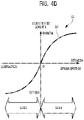
- FIG. 4D is an explanatory diagram of abase bounce target load map conceptually indicating a relation between the sprung speed and a bounce target load varying according to the sprung speed.
- FIG. 4E is an explanatory diagram of a bounce target load map conceptually indicating a relation between the sprung speed and the bounce target load varying according to the sprung speed.
- FIG. 4F is an explanatory diagram of a bounce target load map conceptually indicating a relation between the sprung speed and the bounce target load varying according to the sprung speed.
- FIG. 5 is a flowchart to be used to describe operation of the electric suspension device according to an embodiment of the present invention.
- FIG. 1 is a diagram of an entire configuration common to the electric suspension devices 11 according to the embodiments of the present invention.
- FIG. 2 is a partially cross-sectional view of an electromagnetic actuator 13 forming a part of the electric suspension devices 11 .
- the electric suspension device 11 includes a plurality of electromagnetic actuators 13 each provided for a wheel of a vehicle 10 , and a load control ECU 15 .
- the plurality of electromagnetic actuators 13 and the load control ECU 15 are connected to each other by respective power supply lines 14 (see the solid lines in FIG. 1 ) for supplying driving control power from the load control ECU 15 to the plurality of electromagnetic actuators 13 and respective signal lines 16 (see the broken lines in FIG. 1 ) for sending driving control signals for electric motors 31 (see FIG. 2 ) from the plurality of electromagnetic actuators 13 to the load control ECU 15 .
- a total of four electromagnetic actuators 13 are disposed, each for one of the front wheels (front left wheel and front right wheel) and the rear wheels (rear left wheel and rear right wheel).
- the driving of the electromagnetic actuators 13 provided for the respective wheels is controlled independently of each other for extension-contraction operations at the wheels.
- the plurality of electromagnetic actuators 13 have a common configuration unless otherwise noted. Thus, the configuration of one electromagnetic actuator 13 will be described as a description of the plurality of electromagnetic actuators 13 .
- the electromagnetic actuator 13 includes a base housing 17 , an outer tube 19 , a ball bearing 21 , a ball screw shaft 23 , a plurality of balls 25 , a nut 27 , and an inner tube 29 .
- the base housing 17 supports the proximal end side of the ball screw shaft 23 via the ball bearing 21 such that the ball screw shaft 23 is rotatable about its axis.
- the outer tube 19 is provided on the base housing 17 and accommodates a ball screw mechanism 18 including the ball screw shaft 23 , the plurality of balls 25 , and the nut 27 .
- the plurality of balls 25 roll along a screw groove on the ball screw shaft 23 .
- the nut 27 is engaged with the ball screw shaft 23 via the plurality of balls 25 and converts a rotational motion of the ball screw shaft 23 into a linear motion.
- the inner tube 29 which is coupled to the nut 27 , moves in the axial direction of the outer tube 19 together with the nut 27 .
- the electromagnetic actuator 13 includes an electric motor 31 , a pair of pulleys 33 , and a belt member 35 , as illustrated in FIG. 2 .
- the electric motor 31 is provided on the base housing 17 in parallel to the outer tube 19 .
- the pulleys 33 are mounted on a motor shaft 31 a of the electric motor 31 and the ball screw shaft 23 , respectively. Around these pair of pulleys 33 is stretched the belt member 35 for transmitting the rotational driving force of the electric motor 31 to the ball screw shaft 23 .
- the electric motor 31 is provided with a resolver 37 that detects a rotational angle signal from the electric motor 31 .
- the rotational angle signal from the electric motor 31 detected by the resolver 37 is sent to the load control ECU 15 via the signal line 16 .
- the rotational driving of the electric motor 31 is controlled according to the driving control power supplied from the load control ECU 15 to each of the plurality of the electromagnetic actuators 13 via the corresponding power supply line 14 .
- the present embodiments employ the layout in which the motor shaft 31 a of the electric motor 31 and the ball screw shaft 23 are disposed substantially parallel to each other and coupled to each other, as illustrated in FIG. 2 , to shorten the axial dimension of the electromagnetic actuator 13 .
- a layout may be employed in which the motor shaft 31 a of the electric motor 31 and the ball screw shaft 23 are disposed coaxially with each other and coupled to each other.
- the electromagnetic actuators 13 are provided with a coupling portion 39 at a lower end portion of the base housing 17 .
- This coupling portion 39 is coupled and fixed to an unsprung member not illustrated (such as the lower armor the knuckle on the wheel side).
- an upper end portion 29 a of the inner tube 29 is coupled and fixed to a sprung member not illustrated (such as a strut tower portion on the body side).
- the electromagnetic actuator 13 is provided in parallel to a spring member not illustrated provided between the body and the wheel of the vehicle 10 .
- the electromagnetic actuator 13 configured as above operates as below. Specifically, consider a case where, for example, a thrust related to upward vibration is inputted into the coupling portion 39 from the wheel side of the vehicle 10 . In this case, the inner tube 29 and the nut 27 try to descend together relative to the outer tube 19 receiving the thrust related to the upward vibration. In response to this, the ball screw shaft 23 tries to rotate in the direction corresponding to the descent of the nut 27 . At this moment, the electric motor 31 is caused to generate a rotational driving force in the direction in which the rotational driving force impede the descent of the nut 27 . This rotational driving force of the electric motor 31 is transmitted to the ball screw shaft 23 via the belt member 35 .
- FIG. 3 is a diagram of the configurations inside and around the load control ECU 15 included in the electric suspension device 11 according to the embodiment of the present invention.
- the load control ECU 15 included in the electric suspension device 11 includes a microcomputer that performs various arithmetic processes.
- the load control ECU 15 has a driving control function of controlling the driving of each of the plurality of electromagnetic actuators 13 based on the rotational angle signal from the electric motor 31 detected by the resolver 37 , target loads, and so on to thereby generate a driving force for a damping operation and an extension-contraction operation of the electromagnetic actuator 13 .
- the load control ECU 15 includes an information acquisition unit 41 , a target load computation unit 43 , and a driving control unit 45 , as illustrated in FIG. 3 .
- the information acquisition unit 41 acquires the rotational angle signal from the electric motor 31 detected by the resolver 37 as time-series information on the stroke position and also acquires information on a sprung speed SV by time-differentiating the time-series information on the stroke position.
- the sprung speed SV is the speed of the sprung mass (body) in the vertical direction.
- the information acquisition unit 41 also acquires time-series information on each of a sprung pitch rate PV, a sprung roll rate RV, and a sprung acceleration SA.
- the information on the sprung pitch rate PV and the sprung roll rate RV may be acquired by, for example, a gyro sensor (not illustrated) provided in the vehicle 10 .
- the information on the sprung acceleration SA may be acquired by time-differentiating the information on the sprung speed SV.
- the information acquisition unit 41 acquires information indicating toward which one of the extension side and the contraction side the direction of the sprung speed SV is oriented. Similarly, based on the obtained information on the sprung acceleration SA, the information acquisition unit 41 acquires information indicating toward which one of the extension side and the contraction side the direction of the sprung acceleration SA is oriented.
- the information acquisition unit 41 acquires information on a sprung speed absolute value
- the information acquisition unit 41 further acquires time-series information on each of a vehicle speed VS, the stroke position of the electromagnetic actuator 13 , and a motor current for the electric motor 31 .
- , the vehicle speed VS, the stroke position of the electromagnetic actuator 13 , and the motor current for the electric motor 31 acquired by the information acquisition unit 41 are sent to the target load computation unit 43 .
- the target load computation unit 43 has a function of figuring out the target loads, which are target values for a damping operation and an extension-contraction operation of the electromagnetic actuator 13 , by computation based on the various pieces of information acquired by the information acquisition unit 41 .
- the target load computation unit 43 includes a bounce target value computation unit 47 , a pitch target value computation unit 48 , and a roll target value computation unit 49 , as illustrated in FIG. 3 .
- the bounce target value computation unit 47 computes a bounce target value for controlling the bounce orientation of the vehicle 10 based on information such as the sprung speed SV and the sprung acceleration SA.
- the pitch target value computation unit 48 computes a pitch target value for controlling the pitch orientation of the vehicle 10 based on the sprung pitch rate PV.
- the roll target value computation unit 49 computes a roll target value for controlling the roll orientation of the vehicle 10 based on the sprung roll rate RV.
- the driving control unit 45 calculates a target current value that can achieve the target loads figured out by the target load computation unit 43 .
- the driving control unit 45 then controls the driving of the electric motor 31 included in each of the plurality of electromagnetic actuators 13 such that the motor current for the electric motor 31 follows the target current value calculated.
- the driving of the electric motors 31 of the plurality of electromagnetic actuators 13 is controlled independently of each other.
- the driving control unit 45 can preferably use, for example, an inverter control circuit when generating the driving control power to be supplied to each electric motor 31 .
- FIG. 4A is a diagram conceptually illustrating the configuration of the main part of the load control ECU 15 included in the electric suspension device 11 according to the embodiment of the present invention.
- FIGS. 4B and 4C are explanatory diagrams of sprung speed conversion maps 73 and 75 to be used in adjustment of the width of a dead zone 77 (see FIGS. 4E and 4F ) set in a function in which bounce target values are associated with absolute values
- FIGS. 4D to 4F are explanatory diagrams of a bounce target load map 52 each conceptually indicating a relation between the sprung speed SV and a bounce target load varying according to the sprung speed SV.
- the load control ECU 15 included in the electric suspension device 11 includes the bounce target value computation unit 47 , the pitch target value computation unit 48 , the roll target value computation unit 49 , and an addition unit 69 . Note that the involvement of the pitch target value computation unit 48 and the roll target value computation unit 49 in the present invention is low, and therefore detailed description thereof is omitted.
- the bounce target value computation unit 47 includes a bounce gain setting unit (B gain setting unit) 51 , a sprung speed conversion unit 71 , a bounce target load calculation unit 53 , a primary multiplication unit 55 , an extension-side gain (Ten gain) setting unit 61 , a contraction-side gain (Comp gain) setting unit 63 , a selection unit 65 , and a secondary multiplication unit 67 for the purpose of obtaining a bounce target value that can maintain the bounce orientation appropriately.
- B gain setting unit B gain setting unit
- a sprung speed conversion unit 71 a bounce target load calculation unit 53 , a primary multiplication unit 55 , an extension-side gain (Ten gain) setting unit 61 , a contraction-side gain (Comp gain) setting unit 63 , a selection unit 65 , and a secondary multiplication unit 67 for the purpose of obtaining a bounce target value that can maintain the bounce orientation appropriately.
- a predetermined bounce gain (B gain) is set in the B gain setting unit 51 .
- the B gain set in the B gain setting unit 51 is sent to the primary multiplication unit 55 .
- the sprung speed conversion unit 71 has a function of converting an input-side sprung speed absolute value
- the sprung speed conversion unit 71 When converting the sprung speed SV, the sprung speed conversion unit 71 refers to the information on the sprung speed SV and the information on the sprung acceleration SA acquired by the information acquisition unit 41 , and the sprung speed conversion maps 73 (see FIG. 4B ) and 75 (see FIG. 4C ) as appropriate.
- the sprung speed conversion maps 73 and 75 are tables to be used in the adjustment of the width of the dead zone 77 set in the function in which bounce target values are associated with values of the sprung speed SV (bounce target load map 52 ).
- is abbreviated also as “sprung speed SV” when it is not particularly necessary to distinguish whether the sprung speed SV is an absolute value or not.
- the sprung speed conversion unit 71 converts the input-side sprung speed SVin having a linear characteristic into the output-side sprung speed SVout having a non-linear characteristic by selectively using a suitable one of the sprung speed conversion maps 73 and 75 based on the information on the sprung speed SV and the information on the sprung acceleration SA acquired by the information acquisition unit 41 .
- the information on the sprung speed SV contains information of the sprung speed SV, the direction of the sprung speed SV, and the sprung speed absolute value
- the information on the sprung acceleration SA contains information of the sprung acceleration SA, the direction of the sprung acceleration SA, and a sprung acceleration absolute value
- the value of the output-side sprung speed SVout obtained by the conversion by the sprung speed conversion unit 71 is sent to the bounce target load calculation unit 53 .
- a base sprung speed means an output-side sprung speed SVout that serves as a base (for setting the width of the dead zone 77 at a designated value).
- the range of change in the input-side sprung speed SVin in the base sprung speed conversion map 73 includes a first speed range SV 1 , a second speed range SV 2 , and a third speed range SV 3 , as indicated by the divided horizontal axis in FIG. 4B .
- the first speed range SV 1 is a speed range in which the sprung speed SV is a base boundary speed threshold value SVth_Bbd or less (
- the base boundary speed threshold value SVth_Bbd is a threshold value for designating base boundary points of the dead zone 77 in the entire speed range of the sprung speed SV.
- the base boundary points of the dead zone 77 are set as appropriate by taking into consideration a width of the dead zone 77 that serves as a base (a designated width of the dead zone 77 ).
- the first speed range SV 1 is set to suppress a “jiggling feeling” due to damping force control performed to control damping force for vehicle body vibration.
- “jiggling feeling” is a sensuous expression of an impression which the driver gets when feeling a vehicle body vibration in an intermediate frequency range between a sprung resonance frequency range and an unsprung resonance frequency range.
- the base sprung speed conversion map 73 has such a characteristic that the output-side sprung speed SVout takes a fixed value (zero) regardless of the change in the input-side sprung speed SVin. That is, when the input-side sprung speed SVin is in the first speed range SV 1 ( ⁇ SVth_Bbd ⁇ SV ⁇ SVth_Bbd), the corresponding output-side sprung speed SVout is zero.
- the second and third speed ranges SV 2 and SV 3 illustrated in FIG. 4B are speed ranges in which the input-side sprung speed SVin is greater than the base boundary speed threshold value SVth_Bbd (
- the base sprung speed conversion map 73 has such a characteristic that the output-side sprung speed SVout takes values greater than the input-side sprung speed SVin (SVin ⁇ SVout) except for the transition period in which the input-side sprung speed SVin exceeds the base boundary speed threshold value SVth_Bbd and reaches the output-side sprung speed SVout.
- the second speed range SV 2 is set to suppress a “floating feeling” due to damping force control performed to control damping force for vehicle body vibration.
- the base sprung speed conversion map 73 has such a characteristic that the input-side sprung speed SVin takes values greater than or equal to the output-side sprung speed SVout (SVin ⁇ SVout).
- the third speed range SV 3 is set to suppress a “jerking feeling” due to damping force control for a vehicle body vibration exceeding the sprung resonance frequency in which the sprung speed SV is relatively high.
- jerking feeling is a sensuous expression of an impression which the driver gets when feeling a vehicle body vibration during execution of the damping force control.
- an appropriate value may be set as the base boundary speed threshold value SVth_Bbd by referring to an evaluation result acquired by evaluating a probability density function of the sprung speed SV through tests, simulations, etc. and ensuring, for example, that the distribution ratio of sprung speeds SV appearing in the first speed speed SV 1 , the second speed range SV 2 , and the third speed range SV 3 satisfies a predetermined distribution ratio.
- an adjustment sprung speed means an output-side sprung speed SVout to be used in adjustment of the width of the dead zone 77 .
- the range of change in the input-side sprung speed SVin in the adjustment sprung speed conversion map 75 includes a first speed range SV 1 , a second speed range SV 2 , and a third speed range SV 3 , as indicated by the divided horizontal axis in FIG. 4C .
- the first speed range SV 1 is a speed range in which the sprung speed SV is an adjustment boundary speed threshold value SVth_Abd or less (
- the adjustment boundary speed threshold value SVth_Abd is a threshold value for designating adjustment boundary points of the dead zone 77 in the entire speed range of the sprung speed SV.
- the adjustment boundary points of the dead zone 77 are set as appropriate by taking into consideration a width of the dead zone 77 that is preferable as an adjustment margin.
- the above-mentioned base boundary speed threshold value SVth_Bbd and the adjustment boundary speed threshold value SVth_Abd are such that the latter (SVth_Abd) takes a value smaller than the former (SVth_Bbd) by a speed difference ⁇ SVth, as FIG. 4C illustrates a comparison between them. An adjustment in which the width of the dead zone 77 is made narrower by this speed difference ⁇ SVth is performed.
- the electric suspension device 11 when the behavior of the vehicle satisfies a predetermined vibration suppression condition (specifically described later), an adjustment is performed in which the width of the dead zone 77 is made narrower than the width of the dead zone 77 in the state where this vibration suppression condition is not satisfied.
- This adjustment to narrow the width of the dead zone 77 is executed by selectively using the adjustment sprung speed conversion characteristic in the adjustment sprung speed conversion map 75 , instead of the base sprung speed conversion characteristic in the base sprung speed conversion map 73 .
- the adjustment sprung speed conversion map 75 has such a characteristic that the output-side sprung speed SVout takes a fixed value (zero) regardless of the change in the input-side sprung speed SVin. That is, when the input-side sprung speed SVin is in the first speed range SV 1 ( ⁇ SVth_Abd ⁇ SV ⁇ SVth_Abd), the corresponding output-side sprung speed SVout is zero.
- the second and third speed ranges SV 2 and SV 3 illustrated in FIG. 4C are speed ranges in which the input-side sprung speed SVin is greater than the adjustment boundary speed threshold value SVth_Abd(
- the adjustment sprung speed conversion map 75 has such a characteristic that the output-side sprung speed SVout takes values greater than the input-side sprung speed SVin (SVin ⁇ SVout) except for the transition period in which the input-side sprung speed SVin exceeds the adjustment boundary speed threshold value SVth_Abd and reaches the output-side sprung speed SVout.
- the adjustment sprung speed conversion map 75 has such a characteristic that the input-side sprung speed SVin takes values greater than or equal to the output-side sprung speed SVout (SVin ⁇ SVout).
- an appropriate value may be set as the adjustment boundary speed threshold value SVth_Abd by referring to an evaluation result acquired by evaluating a probability density function of the sprung speed SV through tests, simulations, etc. and ensuring, for example, that the distribution ratio of sprung speeds SV appearing in the first speed speed SV 1 , the second speed range SV 2 , and the third speed range SV 3 satisfies a predetermined distribution ratio.
- the bounce target load calculation unit 53 calculates a value of a bounce target load BTL suitable for the sprung speed SV.
- the bounce target load calculation unit 53 refers to the information on the output-side sprung speed SVout after the conversion by the sprung speed conversion unit 71 , the information on the sprung acceleration SA, and the bounce target load map (see FIG. 4D ) 52 .
- the bounce target load map 52 is a table conceptually indicating a relation between the sprung speed SV and the bounce target load BTL varying according to the sprung speed SV (bounce target load characteristic).
- the value of the bounce target load BTL calculated by the bounce target load calculation unit 53 is sent to the primary multiplication unit 55 .
- target values of a damping force control current may be used in place of the values of the bounce target load BTL.
- the range of change in the sprung speed SV in the bounce target load map 52 includes a 11th speed range SV 11 and a 12th speed range SV 12 , as indicated by the divided horizontal axis in FIG. 4D .
- the 11th speed range SV 11 is a speed range on the extension side in which the sprung speed SV illustrated along the horizontal axis of FIG. 4D is above zero.
- the bounce target load characteristic in the 11th speed range SV 11 in the bounce target load map 52 is such that the higher the sprung speed SV becomes toward the extension side, the larger the bounce target load BTL orientated toward the contraction side becomes in a manner of an infinite geometric series.
- the 12th speed range SV 12 is a speed range on the contraction side in which the sprung speed SV illustrated along the horizontal axis of FIG. 4D is below zero.
- the bounce target load characteristic in the 12th speed range SV 12 in the bounce target load map 52 is such that the higher the sprung speed SV becomes toward the contraction side, the larger the bounce target load BTL orientated toward the extension side becomes in a manner of an infinite geometric series.
- the bounce target load calculation unit 53 refers to the information on the output-side sprung speed SVout after the conversion by the sprung speed conversion unit 71 and the bounce target load map 52 when calculating the bounce target load BTL.
- the bounce target load calculation unit 53 combines the base sprung speed conversion characteristic in the base sprung speed conversion map 73 and the bounce target load characteristic in the bounce target load map 52 illustrated in FIG. 4D to thereby calculate values of the bounce target load BTL having a bounce target load characteristic as illustrated in FIG. 4E .
- a 13th speed range SV 13 as the dead zone 77 is present between the 11th speed range SV 11 and the 12th speed range SV 12 , unlike the bounce target load characteristic in the bounce target load map 52 illustrated in FIG. 4D .
- the 13th speed range SV 13 is a speed range in which the sprung speed SV illustrated along the horizontal axis of FIG. 4E is a first speed threshold value SVth 1 or less (
- the first speed threshold value SVth 1 is a speed threshold value corresponding to the base boundary speed threshold value SVth_Bbd illustrated in FIG. 4B .
- the bounce target load map 52 has such a characteristic that the bounce target load BTL takes a fixed value (zero) regardless of the change in the sprung speed SV. That is, when the sprung speed SV is in the 13th speed range SV 13 ( ⁇ SVth 1 ⁇ SV ⁇ SVth 1 ; the dead zone 77 ), the corresponding bounce target load BTL is zero.
- the bounce target load calculation unit 53 combines the adjustment sprung speed conversion characteristic in the adjustment sprung speed conversion map 75 and the bounce target load characteristic in the bounce target load map 52 illustrated in FIG. 4D to thereby calculate values of the bounce target load BTL having a bounce target load characteristic as illustrated in FIG. 4F .
- a 14th speed range SV 14 as the dead zone 77 is present between the 11th speed range SV 11 and the 12th speed range SV 12 , like the bounce target load characteristic in the bounce target load map 52 illustrated in FIG. 4E .
- the 14th speed range SV 14 is a speed range in which the sprung speed SV illustrated along the horizontal axis of FIG. 4F is a second speed threshold value SVth 2 or less (
- the second speed threshold value SVth 2 is set at a value smaller than the first speed threshold value SVth 1 .
- the width of the dead zone 77 in the bounce target load map 52 illustrated in FIG. 4F is narrower than the width of the dead zone 77 in the bounce target load map 52 illustrated in FIG. 4E .
- the second speed threshold value SVth 2 is a speed threshold value corresponding to the adjustment boundary speed threshold value SVth_Abd illustrated in FIG. 4C .
- the bounce target load map 52 has such a characteristic that the bounce target load BTL takes a fixed value (zero) regardless of the change in the sprung speed SV, as in the example of the 13th speed range SV 13 illustrated in FIG. 4E . That is, when the sprung speed SV is in the 14th speed range SV 14 ( ⁇ SVth 2 ⁇ SV ⁇ SVth 2 ; the dead zone 77 ), the corresponding bounce target load BTL is zero.
- the primary multiplication unit 55 multiplies the B gain set in the B gain setting unit 51 and the value of the bounce target load BTL calculated by the bounce target load calculation unit 53 by each other.
- the result of the multiplication by the primary multiplication unit 55 is sent to the secondary multiplication unit 67 .
- a predetermined extension-side gain (Ten gain) for the sprung speed SV is set in the Ten gain setting unit 61 .
- the Ten gain set in the Ten gain setting unit 61 is sent to the selection unit 65 .
- a predetermined contraction-side gain (Comp gain) for the sprung speed SV is set in the Comp gain setting unit 63 .
- the Comp gain set in the Comp gain setting unit 63 is sent to the selection unit 65 .
- the selection unit 65 selects one of the pieces of information on the Ten gain set in the Ten gain setting unit 61 , the Comp gain set in the Comp gain setting unit 63 , and the sprung speed SV by following a predetermined procedure.
- the piece of information selected by the selection unit 65 is sent to the secondary multiplication unit 67 .
- the secondary multiplication unit 67 multiplies the result of the multiplication by the primary multiplication unit 55 and the piece of information selected by the selection unit 65 by each other.
- the result of the multiplication by the secondary multiplication unit 67 is sent to the addition unit 69 (specifically described later).
- the pitch target value computation unit 48 computes the pitch target value for controlling the pitch orientation of the vehicle 10 based on the sprung pitch rate PV, as mentioned earlier.
- the roll target value computation unit 49 computes the roll target value for controlling the roll orientation of the vehicle 10 based on the sprung roll rate RV, as mentioned earlier.
- the addition unit 69 adds up the result of the multiplication by the secondary multiplication unit 67 belonging to the bounce target value computation unit 47 (bounce target value), the result of the computation by the pitch target value computation unit 48 (pitch target value), and the result of the computation by the roll target value computation unit 49 (roll target value).
- the addition unit 69 forms apart of the “driving control unit 45 ” in the present invention.
- FIG. 5 is a flowchart to be used to describe the operation of the electric suspension device 11 according to the embodiment of the present invention.
- step S 11 illustrated in FIG. 5 the information acquisition unit 41 of the load control ECU 15 acquires the rotational angle signal from each electric motor 31 detected by the resolver 37 as time-series information on the stroke position and acquires information on the sprung speed SV by time-differentiating the time-series information on the stroke position.
- the information acquisition unit 41 acquires information on the sprung pitch rate PV, the sprung roll rate RV, and the sprung acceleration SA.
- the information acquisition unit 41 acquires information on the vehicle speed VS, the stroke position of the electromagnetic actuator 13 , and the motor current for the electric motor 31 .
- the pieces of information on the sprung speed SV, the sprung pitch rate PV, the sprung roll rate RV, the sprung acceleration SA, the vehicle speed VS, the stroke position of the electromagnetic actuator 13 , and the motor current for the electric motor 31 acquired by the information acquisition unit 41 are sent to the target load computation unit 43 .
- step S 12 the bounce target load calculation unit 53 belonging to the target load computation unit 43 of the load control ECU 15 sets the width of the dead zone 77 in the bounce target load characteristic in the bounce target load map 52 at an initial value (see the width of the dead zone 77 in the 13th speed range SV 13 illustrated in FIG. 4E ).
- the sprung speed conversion unit 71 converts the input-side sprung speed SVin into an output-side sprung speed SVout by using the base sprung speed conversion map 73 and outputs the output-side sprung speed SVout.
- the bounce target load calculation unit 53 in turn operates so as to set the width of the dead zone 77 in the bounce target load characteristic in the bounce target load map 52 at the initial value (see the width of the dead zone 77 in the 13th speed range SV 13 illustrated in FIG. 4E ).
- step S 13 the bounce target load calculation unit 53 belonging to the target load computation unit 43 of the load control ECU 15 determines whether or not the sprung speed SV acquired by the information acquisition unit 41 is a predetermined speed threshold value SVth or less (
- step S 13 If the result of the determination made in step S 13 indicates that the sprung speed SV is greater than the predetermined speed threshold value SVth (
- step S 13 If, on the other hand, the result of the determination made in step S 13 indicates that the sprung speed SV is the predetermined speed threshold value SVth or less (
- step S 14 the bounce target load calculation unit 53 belonging to the target load computation unit 43 of the load control ECU 15 determines whether the sprung acceleration SA acquired by the information acquisition unit 41 is greater than a predetermined acceleration threshold value SAth (
- SAth a predetermined acceleration threshold value SAth (
- step S 14 If the result of the determination made in step S 14 indicates that the sprung acceleration SA is the predetermined acceleration threshold value SAth or less (
- step S 14 If, on the other hand, the result of the determination made in step S 14 indicates that the sprung acceleration SA is greater than the predetermined acceleration threshold value SAth (
- the target load computation unit 43 of the load control ECU 15 performs an adjustment in which the width of the dead zone 77 in the bounce target load characteristic in the bounce target load map 52 is made narrower than the width (initial value) of the dead zone 77 in the state where the first vibration suppression condition is not satisfied.
- the predetermined speed threshold value SVth and the predetermined acceleration threshold value SAth may be set at appropriate values based on whether the probability of continuation of vehicle body vibration can be assumed to be high when the sprung speed SV is the predetermined speed threshold value SVth or less and the sprung acceleration SA is greater than the predetermined acceleration threshold value SAth (the first vibration suppression condition is satisfied).
- step S 15 the target load computation unit 43 of the load control ECU 15 determines whether the direction of the sprung speed SV and the direction of the sprung acceleration SA are the same based on the information indicating toward which one of the extension side and the contraction side the direction of the sprung speed SV is oriented and the information indicating toward which one of the extension side and the contraction side the direction of the sprung acceleration SA is oriented, which have been acquired by the information acquisition unit 41 .
- the target load computation unit 43 of the load control ECU 15 determines that the direction of the sprung speed SV and the direction of the sprung acceleration SA are the same if the direction of the sprung speed SV and the direction of the sprung acceleration SA are both oriented toward the extension side or toward the contraction side.
- step S 15 If the result of the determination made in step S 15 indicates that the direction of the sprung speed SV and the direction of the sprung acceleration SA are not the same, the load control ECU 15 causes the process flow to jump to step S 17 .
- step S 15 If, on the other hand, the result of the determination made in step S 15 indicates that the direction of the sprung speed SV and the direction of the sprung acceleration SA are the same (a second vibration suppression condition is satisfied), the load control ECU 15 assumes that the probability of increase of the vehicle body vibration is high, and causes the process flow to advance to the next step S 16 .
- step S 16 the target load computation unit 43 of the load control ECU 15 performs an adjustment in which the width of the dead zone 77 in the bounce target load characteristic in the bounce target load map 52 is made narrower than the width (initial value) of the dead zone 77 in the state where the first vibration suppression condition or the second vibration suppression condition is not satisfied.
- step S 17 if at least one of the first and second vibration suppression conditions in steps S 13 to S 15 has not been satisfied and therefore the adjustment to narrow the width of the dead zone 77 in step S 16 has not been performed, the bounce target value computation unit 47 belonging to the target load computation unit 43 of the load control ECU 15 computes the bounce target load (bounce target value) BTL by referring to the bounce target load characteristic in the bounce target load map 52 having the width of the dead zone 77 set at the initial value in step S 12 .
- step S 17 if the first and second vibration suppression conditions in steps S 13 to S 15 have been satisfied and therefore the adjustment to narrow the width of the dead zone 77 in step S 16 has been performed, the bounce target value computation unit 47 belonging to the target load computation unit 43 of the load control ECU 15 computes the bounce target load (bounce target value) BTL by referring to the bounce target load characteristic in the bounce target load map 52 having the (narrowed) width of the dead zone 77 after the adjustment in step S 16 .
- step S 18 the addition unit 69 belonging to the driving control unit 45 of the load control ECU 15 adds up the result of the multiplication by the secondary multiplication unit 67 belonging to the bounce target value computation unit 47 (bounce target value), the result of the computation by the pitch target value computation unit 48 (pitch target value), and the result of the computation by the roll target value computation unit 49 (roll target value).
- a combined target load is calculated, which is obtained by combining all control target values for the bounce orientation, the pitch orientation, and the roll orientation.
- step S 19 the driving control unit 45 of the load control ECU 15 controls the driving of each electromagnetic actuator 13 according to the combined target load calculated in step S 18 .
- the predetermined first vibration suppression condition is satisfied (the sprung speed SV is the predetermined speed threshold value SVth or less and the sprung acceleration SA is greater than the predetermined acceleration threshold value SAth) and the predetermined second vibration suppression condition is satisfied (the direction of the sprung speed SV and the direction of the sprung acceleration SA are the same)
- the predetermined second vibration suppression condition is satisfied (the direction of the sprung speed SV and the direction of the sprung acceleration SA are the same)
- the target load computation unit 43 of the load control ECU 15 then performs the adjustment in which the width of the dead zone 77 in the bounce target load characteristic in the bounce target load map 52 is made narrower than the width (initial value) of the dead zone 77 in the state where at least one of the first and second vibration suppression conditions is not satisfied.
- the electric suspension device 11 when the predetermined first and second vibration suppression conditions are satisfied, it is assumed that the probability of continuation of the vehicle body vibration is high and the probability of increase of the vehicle body vibration is high, and the adjustment to narrow the width of the dead zone 77 in the bounce target load characteristic in the bounce target load map 52 is performed. In this way, it is possible to appropriately suppress changes in behavior of the vehicle 10 even when the dead zone 77 is set in a speed range including the switch point for the sprung speed SV.
- An electric suspension device 11 based on a first aspect is, as a premise, an electric suspension device 11 including an actuator (electromagnetic actuator 13 ) that is provided between a body and a wheel of a vehicle 10 and generates damping force for damping vibration of the body.
- an actuator electromagnettic actuator 13
- the electric suspension device 11 based on the first aspect includes: an information acquisition unit 41 that acquires information on each of a sprung speed SV and a sprung acceleration SA of the vehicle 10 ; a bounce target value computation unit 47 that computes a bounce target value for controlling a bounce orientation of the vehicle 10 based on the sprung speed SV; a driving control unit 45 that controls driving of the electromagnetic actuator 13 by using a control target load which is based on the bounce target value.
- the bounce target value computation unit 47 has a function (bounce target load map 52 ) in which the bounce target value is associated with the sprung speed SV.
- a dead zone 77 is set in which a fixed value is associated as the bounce target value with changes in the sprung speed SV belonging to a predetermined speed range including a direction switch point at which a direction of the sprung speed SV switches from an extension side to a contraction side or from the extension side to the contraction side.
- the bounce target value computation unit 47 adjusts a width of the dead zone 77 based on the information on the sprung speed SV and the sprung acceleration SA.
- the information acquisition unit 41 acquires the information on each of the sprung speed SV and the sprung acceleration SA of the vehicle 10 .
- the bounce target value computation unit 47 computes the bounce target value for controlling the bounce orientation of the vehicle 10 based on the sprung speed SV.
- the driving control unit 45 controls the driving of the electromagnetic actuator 13 by using the control target load that is based on the bounce target value.
- the width of the dead zone 77 is strongly correlated to the accuracy of the control of changes in behavior of the vehicle 10 . Also, the information on the sprung speed SV and the sprung acceleration SA is strongly correlated to the vibration suppression and convergence performance for vehicle body vibration.
- the bounce target value computation unit 47 is therefore configured to adjust the width of the dead zone 77 based on the information on the sprung speed SV and the sprung acceleration SA.
- the bounce target value computation unit 47 adjusts the width of the dead zone 77 based on the information on the sprung speed SV and the sprung acceleration SA. In this way, even when the dead zone 77 is set in a speed range including the switch point for the sprung speed SV, it is possible to enhance the vibration suppression and convergence performance for vehicle body vibration and thus appropriately suppress changes in behavior of the vehicle 10 .
- an electric suspension device 11 based on a second aspect is the electric suspension device 11 based on the first aspect, in which When a first vibration suppression condition that the sprung speed SV is a predetermined speed threshold value SVth or less and the sprung acceleration SA is greater than a predetermined acceleration threshold value SAth is satisfied, the bounce target value computation unit 47 performs an adjustment in which the width of the dead zone 77 is made narrower than the width of the dead zone 77 in a state where the first vibration suppression condition is not satisfied, and performs computation of the bounce target value by using the bounce target load map 52 in which the dead zone 77 after the adjustment is set.
- the driving control unit 45 may be configured to control the driving of the electromagnetic actuator 13 by using a control target load which is based on the bounce target value obtained by the computation.
- the bounce target value computation unit 47 performs the adjustment in which the width of the dead zone 77 is made narrower than the width of the dead zone 77 in the state where the first vibration suppression condition is not satisfied.
- the bounce target value computation unit 47 performs the computation of the bounce target value by using the bounce target load map 52 in which the dead zone 77 after the adjustment is set.
- the probability of continuation of vehicle body vibration is high when the first vibration suppression condition that the sprung speed SV is the predetermined speed threshold value SVth or less and the sprung acceleration SA is greater than the predetermined acceleration threshold value SAth is satisfied.
- the range in the bounce target load map 52 across which the bounce target value changes with change in the sprung acceleration SA becomes wider by the amount by which the width of the dead zone 77 is narrowed. Accordingly, changes in the sprung acceleration SA can be finely reflected on the bounce target value.
- the driving control unit 45 then controls the driving of the electromagnetic actuator 13 by using a control target load which is based on the bounce target value obtained by the computation.
- the bounce target value computation unit 47 performs the adjustment in which the width of the dead zone 77 is made narrower than the width of the dead zone 77 in the state where the vibration suppression condition is not satisfied. In this way, even when the dead zone 77 is set in a speed range including the switch point for the sprung speed SV, it is possible to enhance the vibration suppression and convergence performance for vehicle body vibration to a greater extent and thus suppress changes in behavior of the vehicle 10 more appropriately than the advantageous effect achieved by the electric suspension device 11 based on the first aspect.
- an electric suspension device 11 based on a third aspect is the electric suspension device 11 based on the first or second aspect, in which the information acquisition unit 41 further acquires information on each of the direction of the sprung speed SV of the vehicle 10 and a direction of the sprung acceleration SA of the vehicle 10 .
- the bounce target value computation unit 47 When a second vibration suppression condition that the direction of the sprung speed SV and the direction of the sprung acceleration SA are same is satisfied, the bounce target value computation unit 47 performs an adjustment in which the width of the dead zone 77 is made narrower than the width of the dead zone 77 in a state where the second vibration suppression condition is not satisfied.
- the bounce target value computation unit 47 performs computation of the bounce target value by using the bounce target load map 52 in which the dead zone 77 after the adjustment is set.
- the range in the bounce target load map 52 across which the bounce target value changes with change in the sprung acceleration SA becomes wider by the amount by which the width of the dead zone 77 is narrowed. Accordingly, changes in the sprung acceleration SA can be finely reflected on the bounce target value.
- the driving control unit 45 then controls the driving of the electromagnetic actuator 13 by using a control target load which is based on the bounce target value obtained by the computation.
- the bounce target value computation unit 47 performs the adjustment in which the width of the dead zone 77 is made narrower than the width of the dead zone 77 in the state where the second vibration suppression condition is not satisfied. In this way, even when the dead zone 77 is set in a speed range including the switch point for the sprung speed SV, it is possible to enhance the vibration suppression and convergence performance for vehicle body vibration to a greater extent and thus suppress changes in behavior of the vehicle 10 more appropriately than the advantageous effect achieved by the electric suspension device 11 based on the first aspect.
- the bounce target value computation unit 47 performs an adjustment in which the width of the dead zone 77 is made narrower than the width of the dead zone 77 in a state where at least one of the first and second vibration suppression conditions is not satisfied. In this way, even when the dead zone 77 is set in a speed range including the switch point for the sprung speed SV, it is possible to enhance the vibration suppression and convergence performance for vehicle body vibration to an even greater extent and thus suppress changes in behavior of the vehicle 10 even more appropriately than the advantageous effect achieved by the electric suspension device 11 based on the first or second aspect.
- the electromagnetic actuator 13 to which the rotational driving force of the electric motor 31 converted in the vertical stroke direction is applied has been described as an example of the member corresponding to the actuator according to the present invention.
- the present invention is not limited to this example.
- a publicly known mono-tube (de Carbon) adjustable damper as disclosed in, for example, Japanese Patent Application Publication 2015-47906 may be employed as the member corresponding to the actuator according to the present invention.
- This adjustable damper includes a circular cylinder filled with a magnetorheological fluid (MRF) and a piston rod inserted therein so as to be axially slidable.
- MRF magnetorheological fluid
- a piston mounted to the distal end of the piston rod partitions the inside of the cylinder into an upper oil chamber and a lower oil chamber.
- This piston is provided with a communication channel through which the upper oil chamber and the lower oil chamber communicate with each other, and a MLV coil located inside this communication channel.
- the bounce target load characteristic in the bounce target load map 52 has been described by taking the example illustrated in FIGS. 4D to 4F .
- the present invention is not limited to this example.
- the bounce target load characteristic in the bounce target load map 52 is not particularly limited. A necessary bounce target load characteristic may be employed as appropriate.
- the electric suspension device 11 has been described by taking an example in which the combination of the sprung speed conversion unit 71 and the bounce target load calculation unit 53 is used as the configuration for performing the adjustment to narrow the width of the dead zone 77 in the bounce target load characteristic in the bounce target load map 52 .
- the present invention is not limited to this example.
- a necessary configuration may be employed as appropriate as the configuration for performing the adjustment to narrow the width of the dead zone 77 in the bounce target load characteristic in the bounce target load map 52 .
- the electric suspension device 11 has been described by taking an example in which the number of adjustment stages for performing the adjustment to narrow the width of the dead zone 77 in the bounce target load characteristic in the bounce target load map 52 is one (see FIGS. 4E and 4F ).
- the present invention is not limited to this example.
- any number of stages may be employed as appropriate as the number of adjustment stages for performing the adjustment to narrow the width of the dead zone 77 in the bounce target load characteristic in the bounce target load map 52 .
- the information on the sprung speed SV of the vehicle 10 and the information on the sprung acceleration SA of the vehicle 10 are used in combination with each other as parameters to be referred to to determine whether to perform the adjustment of the width of the dead zone 77 . This makes it possible to accurately predict whether the vehicle body vibration is going to increase or to converge.
- the adjustment to narrow the width of the dead zone 77 (or an adjustment to widen the width of the dead zone 77 ) can be performed in a timely and appropriate manner based on the result of the prediction of the vehicle body vibration.
- phase difference between the sprung speed SV and the sprung acceleration SA it is possible to predict, for example, that the probability of continuation of the vehicle body vibration is high when the first vibration suppression condition that the sprung speed SV is the predetermined speed threshold value SVth or less and the sprung acceleration SA is greater than the predetermined acceleration threshold value SAth is satisfied.
- the probability of convergence of the vehicle body vibration is high when a condition that the sprung speed SV is the predetermined speed threshold value SVth or less and the sprung acceleration SA is the predetermined acceleration threshold value SAth or less is satisfied.
- the configuration may be such that when it is predicted that the probability of continuation of the vehicle body vibration is high, the adjustment to widen the width of the dead zone 77 is performed to enhance the vibration convergence and suppression performance for the vehicle body vibration.
- the electric suspension device 11 has been described by taking an example in which a total of four electromagnetic actuators 13 are disposed for both the front wheels (front left wheel and front right wheel) and the rear wheels (rear left wheel and rear right wheel).
- the present invention is not limited to this example.
- a configuration in which a total of two electromagnetic actuators 13 are disposed for either the front wheels or the rear wheels may be employed.
- the driving control unit 45 controls the driving of the plurality of electromagnetic actuators 13 independently of each other.
- the driving control unit 45 may control the driving of the electromagnetic actuators 13 provided for the four wheels independently on a wheel-by-wheel basis.
- the driving control unit 45 may control the driving of the electromagnetic actuators 13 provided for the four wheels such that the driving of the electromagnetic actuators 13 on the front wheels is controlled independently of that of the electromagnetic actuators 13 on the rear wheels or the driving of the electromagnetic actuators 13 on the left wheels is controlled independently of that of the electromagnetic actuators 13 on the right wheels.
Landscapes
- Engineering & Computer Science (AREA)
- Mechanical Engineering (AREA)
- Vehicle Body Suspensions (AREA)
Abstract
Description
Claims (2)
Applications Claiming Priority (3)
| Application Number | Priority Date | Filing Date | Title |
|---|---|---|---|
| JP2020-047007 | 2020-03-17 | ||
| JP2020047007A JP6993450B2 (en) | 2020-03-17 | 2020-03-17 | Electric suspension device |
| JPJP2020-047007 | 2020-03-17 |
Publications (2)
| Publication Number | Publication Date |
|---|---|
| US20210291609A1 US20210291609A1 (en) | 2021-09-23 |
| US11433727B2 true US11433727B2 (en) | 2022-09-06 |
Family
ID=77691403
Family Applications (1)
| Application Number | Title | Priority Date | Filing Date |
|---|---|---|---|
| US17/199,799 Active US11433727B2 (en) | 2020-03-17 | 2021-03-12 | Electric suspension device |
Country Status (3)
| Country | Link |
|---|---|
| US (1) | US11433727B2 (en) |
| JP (1) | JP6993450B2 (en) |
| CN (1) | CN113400882B (en) |
Families Citing this family (2)
| Publication number | Priority date | Publication date | Assignee | Title |
|---|---|---|---|---|
| JP6807975B2 (en) * | 2019-04-12 | 2021-01-06 | 本田技研工業株式会社 | Electric suspension device |
| WO2021078909A1 (en) * | 2019-10-25 | 2021-04-29 | ILJIN Bearing GmbH | Electromechanical vehicle height adjustment unit and vehicle height adjustment method |
Citations (6)
| Publication number | Priority date | Publication date | Assignee | Title |
|---|---|---|---|---|
| US5445405A (en) * | 1993-04-20 | 1995-08-29 | Aisin Seiki Kabushiki Kaisha | Suspension control apparatus |
| US5671142A (en) * | 1994-08-23 | 1997-09-23 | Nissan Motor Co., Ltd. | Apparatus and method for controlling damping force exhibited in vehicular damping force variable shock absorber |
| US20100032912A1 (en) * | 2006-10-13 | 2010-02-11 | Toyota Jidosha Kabushiki Kaisha | Suspension system for vehicle |
| US20130060422A1 (en) * | 2010-05-11 | 2013-03-07 | Toyota Jidosha Kabushiki Kaisha | Suspension device |
| US20150066295A1 (en) * | 2013-08-30 | 2015-03-05 | Honda Motor Co., Ltd. | Suspension control device |
| US20210354523A1 (en) * | 2018-10-12 | 2021-11-18 | Hitachi Astemo, Ltd. | Suspension control device |
Family Cites Families (9)
| Publication number | Priority date | Publication date | Assignee | Title |
|---|---|---|---|---|
| JP3080254B2 (en) * | 1991-12-26 | 2000-08-21 | 株式会社ユニシアジェックス | Vehicle suspension system |
| JPH06227229A (en) * | 1993-02-03 | 1994-08-16 | Unisia Jecs Corp | Vehicle suspension |
| JP3673847B2 (en) * | 1993-12-28 | 2005-07-20 | 株式会社日立製作所 | Suspension control device |
| JPH07285309A (en) * | 1994-04-18 | 1995-10-31 | Unisia Jecs Corp | Vehicle suspension |
| JP3722128B2 (en) * | 2003-02-05 | 2005-11-30 | 日産自動車株式会社 | VEHICLE ELECTRIC SUSPENSION DEVICE AND MOTOR CONTROL METHOD FOR VEHICLE ELECTRONIC SUSPENSION DEVICE |
| JP4920006B2 (en) * | 2008-05-15 | 2012-04-18 | トヨタ自動車株式会社 | Vehicle suspension system |
| JP6417443B1 (en) * | 2017-04-17 | 2018-11-07 | 本田技研工業株式会社 | Electromagnetic suspension device |
| JP6486414B2 (en) * | 2017-06-16 | 2019-03-20 | 本田技研工業株式会社 | Electromagnetic suspension device |
| JP6480983B2 (en) | 2017-06-16 | 2019-03-13 | 本田技研工業株式会社 | Electromagnetic suspension device |
-
2020
- 2020-03-17 JP JP2020047007A patent/JP6993450B2/en active Active
-
2021
- 2021-03-09 CN CN202110257747.5A patent/CN113400882B/en active Active
- 2021-03-12 US US17/199,799 patent/US11433727B2/en active Active
Patent Citations (7)
| Publication number | Priority date | Publication date | Assignee | Title |
|---|---|---|---|---|
| US5445405A (en) * | 1993-04-20 | 1995-08-29 | Aisin Seiki Kabushiki Kaisha | Suspension control apparatus |
| US5671142A (en) * | 1994-08-23 | 1997-09-23 | Nissan Motor Co., Ltd. | Apparatus and method for controlling damping force exhibited in vehicular damping force variable shock absorber |
| US20100032912A1 (en) * | 2006-10-13 | 2010-02-11 | Toyota Jidosha Kabushiki Kaisha | Suspension system for vehicle |
| US20130060422A1 (en) * | 2010-05-11 | 2013-03-07 | Toyota Jidosha Kabushiki Kaisha | Suspension device |
| US20150066295A1 (en) * | 2013-08-30 | 2015-03-05 | Honda Motor Co., Ltd. | Suspension control device |
| JP2015047906A (en) | 2013-08-30 | 2015-03-16 | 本田技研工業株式会社 | Suspension control device |
| US20210354523A1 (en) * | 2018-10-12 | 2021-11-18 | Hitachi Astemo, Ltd. | Suspension control device |
Also Published As
| Publication number | Publication date |
|---|---|
| US20210291609A1 (en) | 2021-09-23 |
| JP6993450B2 (en) | 2022-01-13 |
| CN113400882B (en) | 2022-04-22 |
| CN113400882A (en) | 2021-09-17 |
| JP2021146818A (en) | 2021-09-27 |
Similar Documents
| Publication | Publication Date | Title |
|---|---|---|
| US11440367B2 (en) | Electric suspension device | |
| KR102448779B1 (en) | suspension control unit | |
| US7406371B2 (en) | Suspension control system | |
| US10471788B2 (en) | Electromagnetic suspension apparatus | |
| CN101795880B (en) | Suspension system for a vehicle including an electromagnetic actuator | |
| US10647172B2 (en) | Electromagnetic suspension apparatus | |
| US8090500B2 (en) | Control device for a variable damper | |
| US11186134B2 (en) | Electrically powered suspension system | |
| US20210291609A1 (en) | Electric suspension device | |
| US11230155B2 (en) | Control apparatus for suspension apparatus and suspension system | |
| US11518207B2 (en) | Electrically powered suspension system | |
| US12285985B2 (en) | Control apparatus | |
| US11618293B2 (en) | Electrically powered suspension system including an electromagnetic actuator, information acquirer, and drive force arithmetic part | |
| JP2017165283A (en) | Vehicle suspension system | |
| JPS61193907A (en) | Active suspension controller | |
| US12036836B2 (en) | Electrically powered suspension system | |
| US10857848B2 (en) | Electromagnetic suspension device | |
| US11396214B2 (en) | Electric suspension device | |
| JP2013241075A (en) | Suspension control device | |
| JP5131682B2 (en) | Control device for variable damping force damper | |
| JP2022149935A (en) | electric suspension device | |
| JPH0427614A (en) | Suspension device of vehicle | |
| JP2010111208A (en) | Suspension device |
Legal Events
| Date | Code | Title | Description |
|---|---|---|---|
| FEPP | Fee payment procedure |
Free format text: ENTITY STATUS SET TO UNDISCOUNTED (ORIGINAL EVENT CODE: BIG.); ENTITY STATUS OF PATENT OWNER: LARGE ENTITY |
|
| AS | Assignment |
Owner name: HONDA MOTOR CO., LTD., JAPAN Free format text: ASSIGNMENT OF ASSIGNORS INTEREST;ASSIGNORS:GOTO, YUYA;KANDA, RYOMA;REEL/FRAME:056246/0888 Effective date: 20210402 |
|
| STPP | Information on status: patent application and granting procedure in general |
Free format text: DOCKETED NEW CASE - READY FOR EXAMINATION |
|
| STPP | Information on status: patent application and granting procedure in general |
Free format text: NON FINAL ACTION MAILED |
|
| STPP | Information on status: patent application and granting procedure in general |
Free format text: NOTICE OF ALLOWANCE MAILED -- APPLICATION RECEIVED IN OFFICE OF PUBLICATIONS |
|
| STPP | Information on status: patent application and granting procedure in general |
Free format text: PUBLICATIONS -- ISSUE FEE PAYMENT VERIFIED |
|
| STCF | Information on status: patent grant |
Free format text: PATENTED CASE |
|
| MAFP | Maintenance fee payment |
Free format text: PAYMENT OF MAINTENANCE FEE, 4TH YEAR, LARGE ENTITY (ORIGINAL EVENT CODE: M1551); ENTITY STATUS OF PATENT OWNER: LARGE ENTITY Year of fee payment: 4 |