US11433449B2 - Drawing-out tool for sheet metal - Google Patents
Drawing-out tool for sheet metal Download PDFInfo
- Publication number
- US11433449B2 US11433449B2 US16/372,967 US201916372967A US11433449B2 US 11433449 B2 US11433449 B2 US 11433449B2 US 201916372967 A US201916372967 A US 201916372967A US 11433449 B2 US11433449 B2 US 11433449B2
- Authority
- US
- United States
- Prior art keywords
- sheet metal
- housing
- light source
- illumination unit
- accommodating
- Prior art date
- Legal status (The legal status is an assumption and is not a legal conclusion. Google has not performed a legal analysis and makes no representation as to the accuracy of the status listed.)
- Active, expires
Links
Images


Classifications
-
- B—PERFORMING OPERATIONS; TRANSPORTING
- B21—MECHANICAL METAL-WORKING WITHOUT ESSENTIALLY REMOVING MATERIAL; PUNCHING METAL
- B21D—WORKING OR PROCESSING OF SHEET METAL OR METAL TUBES, RODS OR PROFILES WITHOUT ESSENTIALLY REMOVING MATERIAL; PUNCHING METAL
- B21D31/00—Other methods for working sheet metal, metal tubes, metal profiles
- B21D31/005—Incremental shaping or bending, e.g. stepwise moving a shaping tool along the surface of the workpiece
-
- B—PERFORMING OPERATIONS; TRANSPORTING
- B21—MECHANICAL METAL-WORKING WITHOUT ESSENTIALLY REMOVING MATERIAL; PUNCHING METAL
- B21D—WORKING OR PROCESSING OF SHEET METAL OR METAL TUBES, RODS OR PROFILES WITHOUT ESSENTIALLY REMOVING MATERIAL; PUNCHING METAL
- B21D1/00—Straightening, restoring form or removing local distortions of sheet metal or specific articles made therefrom; Stretching sheet metal combined with rolling
- B21D1/06—Removing local distortions
- B21D1/08—Removing local distortions of hollow bodies made from sheet metal
-
- B—PERFORMING OPERATIONS; TRANSPORTING
- B21—MECHANICAL METAL-WORKING WITHOUT ESSENTIALLY REMOVING MATERIAL; PUNCHING METAL
- B21D—WORKING OR PROCESSING OF SHEET METAL OR METAL TUBES, RODS OR PROFILES WITHOUT ESSENTIALLY REMOVING MATERIAL; PUNCHING METAL
- B21D1/00—Straightening, restoring form or removing local distortions of sheet metal or specific articles made therefrom; Stretching sheet metal combined with rolling
- B21D1/12—Straightening vehicle body parts or bodies
-
- B—PERFORMING OPERATIONS; TRANSPORTING
- B21—MECHANICAL METAL-WORKING WITHOUT ESSENTIALLY REMOVING MATERIAL; PUNCHING METAL
- B21D—WORKING OR PROCESSING OF SHEET METAL OR METAL TUBES, RODS OR PROFILES WITHOUT ESSENTIALLY REMOVING MATERIAL; PUNCHING METAL
- B21D11/00—Bending not restricted to forms of material mentioned in only one of groups B21D5/00, B21D7/00, B21D9/00; Bending not provided for in groups B21D5/00 - B21D9/00; Twisting
- B21D11/20—Bending sheet metal, not otherwise provided for
-
- B—PERFORMING OPERATIONS; TRANSPORTING
- B21—MECHANICAL METAL-WORKING WITHOUT ESSENTIALLY REMOVING MATERIAL; PUNCHING METAL
- B21D—WORKING OR PROCESSING OF SHEET METAL OR METAL TUBES, RODS OR PROFILES WITHOUT ESSENTIALLY REMOVING MATERIAL; PUNCHING METAL
- B21D11/00—Bending not restricted to forms of material mentioned in only one of groups B21D5/00, B21D7/00, B21D9/00; Bending not provided for in groups B21D5/00 - B21D9/00; Twisting
- B21D11/22—Auxiliary equipment, e.g. positioning devices
-
- B—PERFORMING OPERATIONS; TRANSPORTING
- B21—MECHANICAL METAL-WORKING WITHOUT ESSENTIALLY REMOVING MATERIAL; PUNCHING METAL
- B21D—WORKING OR PROCESSING OF SHEET METAL OR METAL TUBES, RODS OR PROFILES WITHOUT ESSENTIALLY REMOVING MATERIAL; PUNCHING METAL
- B21D22/00—Shaping without cutting, by stamping, spinning, or deep-drawing
- B21D22/20—Deep-drawing
-
- B—PERFORMING OPERATIONS; TRANSPORTING
- B21—MECHANICAL METAL-WORKING WITHOUT ESSENTIALLY REMOVING MATERIAL; PUNCHING METAL
- B21D—WORKING OR PROCESSING OF SHEET METAL OR METAL TUBES, RODS OR PROFILES WITHOUT ESSENTIALLY REMOVING MATERIAL; PUNCHING METAL
- B21D35/00—Combined processes according to or processes combined with methods covered by groups B21D1/00 - B21D31/00
- B21D35/002—Processes combined with methods covered by groups B21D1/00 - B21D31/00
-
- B—PERFORMING OPERATIONS; TRANSPORTING
- B21—MECHANICAL METAL-WORKING WITHOUT ESSENTIALLY REMOVING MATERIAL; PUNCHING METAL
- B21D—WORKING OR PROCESSING OF SHEET METAL OR METAL TUBES, RODS OR PROFILES WITHOUT ESSENTIALLY REMOVING MATERIAL; PUNCHING METAL
- B21D53/00—Making other particular articles
- B21D53/36—Making other particular articles clips, clamps, or like fastening or attaching devices, e.g. for electric installation
Definitions
- the present invention relates to a drawing-out tool for sheet metal for drawing-out a recess part on a sheet metal surface during sheet metal process.
- a drawing-out tool for sheet metal shown in JP 5716889 B1 includes: a center shaft; a first operation means arranged to an apex part of the center shaft and provided with a bit weldable to a sheet metal surface; a second operation means for pulling-up the first operation means; a support member for supporting the first operation means; an energization mechanism for supplying electric current to the bit; a leg body for supporting the second operation means; and a power source cord for supplying electricity to the energization mechanism, and is used by connecting the other end side of the power source cord to a welder, and makes it possible to perform a series of sheet metal operations such as supplying electric current to the bit, welding the apex of the bit to a sheet metal correction front surface to pull up a recess part of the sheet metal correction surface, furthermore, after pulling-up of the recess part, releasing the welding of the bit.
- dust, metal dust, soil dust and the like are present abundantly. Therefore, the followings are required, that is, (1) dust, metal dust, soil dust and the like do not mingle in or attach to an energization mechanism for supplying electric current to the bit, and (2) a trouble such as contact failure is not generated in an electric system.
- the working field of the sheet metal process is generally not guaranteed with sufficient lighting, therefore, in order to make it possible to perform the sheet metal process efficiently in a short time even in a dark working field, at least, (1) sufficient lighting is secured during the sheet metal process, and (2) an operator can visually clearly observe unevenness of a sheet metal surface are desired from the viewpoint of an operation environment are desired.
- a drawing-out tool for sheet metal shown in JP 5716889 B1 is not necessarily sufficient in protection of an electric system of an energization mechanism for supplying electric current to a bit, furthermore, the drawing-out tool for sheet metal itself is not provided with a means for illuminating a sheet metal surface.
- an object of the present invention is to provide a drawing-out tool for sheet metal that is less in failure and excellent in the durability and has excellent handling property by shielding dust, metal dust, soil dust and the like from mingling in and attaching to an electric system, and by evading a trouble from occurring in an electric system.
- Another object of the present invention is to provide a drawing-out tool for sheet metal which can secure sufficient brightness during a sheet metal process, can clearly see a relief on a sheet metal surface in the neighborhood of the bit necessary to be subjected to sheet metal process, and can efficiently perform the sheet metal process while illuminating irregular parts necessary to be subjected to the sheet metal process even when the working field is poorly illuminated.
- Still another object of the present invention is to provide a drawing-out tool for sheet metal which can evade generation of a shadow due to the center shaft or the bit on a sheet metal part even when the sheet metal surface is illuminated, can secure brightness sufficient for performing the sheet metal process, and can perform the sheet metal process while illuminating the neighborhood of the welded bit in a state where the shadow is not present.
- Another object of the present invention is to provide a drawing-out tool for sheet metal which constitutes a compact illumination unit by integrating illumination members in a housing, can freely control an amount of light and can accurately illuminate a place necessary to be subjected to the sheet metal process.
- a drawing-out tool for sheet metal which may secure sufficient brightness during the sheet metal process, may clearly grasp the relief on the sheet metal surface in the neighborhood of a bit necessary to be subjected to the sheet metal process, and may efficiently perform the sheet metal process by illuminating a sheet metal place necessary to be subjected to the sheet metal process even when the working field is poorly illuminated may be obtained.
- a drawing-out tool for sheet metal which may evade generation of a shadow due to the center shaft or bit even when a sheet metal surface is illuminated, may secure the brightness sufficient when performing the sheet metal process, and may perform the sheet metal process by illuminating the neighborhood of a welded bit in a state where a shadow is not present is obtained.
- a drawing-out tool for sheet metal which may be compactly constituted by integrating illumination members constituting an illumination unit in a housing and may accurately illuminate a position necessary to be subjected to the sheet metal process by freely adjusting an amount of light is obtained.
- FIG. 1 is a perspective view of a drawing-out tool for sheet metal relating to the present invention, and a perspective view showing a left hand grasping a handle constituting a first operation means and a right hand grasping a second operation means by a virtual line (dashed dotted line);
- FIG. 2 is a perspective view obtained by seeing up a back surface of the drawing-out tool for sheet metal shown in FIG. 1 from a bottom surface side;
- FIG. 3 is a back view of the drawing-out tool for sheet metal shown in FIG. 1 ;
- FIG. 4 is a right side view of the drawing-out tool for sheet metal shown in FIG. 1 ;
- FIG. 5 is a bottom view of the drawing-out tool for sheet metal shown in FIG. 1 ;
- FIG. 6 is a view in which a flow of electric current during energization is drawn in an X-X cross-sectional view shown in FIG. 3 ;
- FIG. 7 is a perspective view of a state where a body and a leg body of the drawing-out tool for sheet metal shown in FIG. 1 are separated;
- FIG. 8 is an exploded perspective view showing constituent components of the body of the drawing-out tool for sheet metal shown in FIG. 1 ;
- FIG. 9 is a bottom view of a state where a light diffusion plate of the drawing-out tool for sheet metal shown in FIG. 1 is removed;
- FIG. 10 is a front view of a printed circuit board in which LED light sources or the like are embedded
- FIG. 11 is a back view of the printed circuit board in which the LED light sources or the like are embedded;
- FIG. 12 is a right side view of FIG. 10 ;
- FIG. 13 is a schematic view showing a wiring to the LED light sources or the like.
- FIG. 14 is a circuit diagram of an illumination part that constitutes an illumination unit and is provided with an LED light source;
- FIG. 15 is a front view of a light diffusion plate
- FIG. 16 is a back view of the light diffusion plate
- FIG. 17 is a right side view of FIG. 15 ;
- FIG. 18 is a perspective view showing an essential part of the drawing-out tool for sheet metal in which an energization mechanism is incorporated;
- FIG. 19 is an exploded perspective view showing an essential part of the drawing-out tool for sheet metal in which the energization mechanism is incorporated and showing by exploding constituent components of the energization mechanism;
- FIG. 20 is a Y-Y cross-section enlarged schematic view of FIG. 18 ;
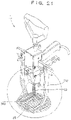
- FIG. 21 is a perspective view showing a state where an illumination unit of the drawing-out tool for sheet metal shown in FIG. 1 is turned on;
- FIG. 22 is an essential part perspective view of a sheet metal surface showing a state where the illumination unit of the drawing-out tool for sheet metal shown in FIG. 1 is turned on and showing a state where a shadow due to a center shaft or a bit is not generated at a position to be subjected to a sheet metal process;
- FIG. 23 is an essential part perspective view of a sheet metal surface showing a state where the light diffusion plate is removed from the drawing-out tool for sheet metal shown in FIG. 1 and the illumination unit is turned on, and a state where a shadow due to a center shaft or a bit is generated at a position to be subjected to the sheet metal process.
- FIG. 24 is an essential part perspective view of a sheet metal surface showing a state where the light diffusion plate is removed from the drawing-out tool for sheet metal shown in FIG. 1 and the illumination unit is turned on, and a state where a shadow due to the center shaft or the bit overlaps with the irregularity on the sheet metal surface to be difficult to see a relief of a surface necessary to be subjected to the sheet metal process;
- FIG. 25 is a perspective view showing a use state of the drawing-out tool for sheet metal shown in FIG. 1 ;
- a drawing-out tool for sheet metal includes: a center shaft; a first operation means provided with a bit arranged to an apex part of the center shaft and weldable to a sheet metal surface; a second operation means for pulling-up the first operation means; an energization mechanism for supplying electric current to the bit; and a leg body for supporting the second operation means, wherein a housing for accommodating an illumination unit and the illumination unit for illuminating the sheet metal surface accommodated in the housing are provided.
- the housing preferably includes: a space for accommodating the energization mechanism; and a power source accommodating part for accommodating a power source for a light source constituting the illumination unit.
- the illumination unit preferably includes: a light source incorporated in the housing; a power source for the light source for supplying electric power to the light source; and a light diffusion plate for diffusing light supplied from the light source, wherein the light source is fixed on a printed circuit board; and the printed circuit board and the light diffusion plate are preferably arranged correspondingly isolated.
- a drawing-out tool for sheet metal is also made into a drawing-out tool for sheet metal including: a center shaft; a first operation means provided with a bit arranged to an apex part of the center shaft and weldable to a sheet metal surface; a second operation means for pulling-up the first operation means; an energization mechanism for supplying electric current to the bit; and a leg body for supporting the second operation means, wherein a housing for accommodating an illumination unit and the illumination unit for illuminating the sheet metal surface accommodated in the housing are provided; wherein the housing includes a space for accommodating the energization mechanism, and a power source accommodating part for accommodating a power source for a light source constituting the illumination unit; wherein the illumination unit includes a light source incorporated in the housing, the power source for a light source for supplying electric power to the light source, and a light diffusion plate for a diffusing light supplied from the light source; wherein the light source is fixed on a printed circuit board, and the printed circuit board and
- a drawing-out tool for sheet metal is also made into a drawing-out tool for sheet metal including: a center shaft; a first operation means provided with a bit arranged to an apex part of the center shaft and weldable to a sheet metal surface; a second operation means for pulling-up the first operation means; a support member for supporting the first operation means; an energization mechanism for supplying electric current to the bit; and a leg body for supporting the second operation means, wherein a housing for accommodating an illumination unit and the illumination unit for illuminating the sheet metal surface accommodated in the housing are provided; wherein the housing includes a space for accommodating the energization mechanism, and a power source accommodating part for accommodating a power source for a light source for constituting the illumination unit; wherein the illumination unit includes a light source incorporated in the housing, the power source for a light source for supplying electric power to the light source, and a light diffusion plate for a diffusing light supplied from the light source; wherein the light source
- a drawing-out tool for sheet metal is also made into a drawing-out tool for sheet metal including: a center shaft; a first operation means provided with a bit arranged to an apex part of the center shaft and weldable to a sheet metal surface; a second operation means for pulling-up the first operation means; a support member for supporting the first operation means; an energization mechanism for supplying electric current to the bit; a leg body for supporting the second operation means; and a power cord for supplying electricity to the energization mechanism, wherein a housing for accommodating an illumination unit and the illumination unit for illuminating the sheet metal surface accommodated in the housing are provided; wherein the housing includes a space for accommodating the energization mechanism, and a power source accommodating part for accommodating a power source for a light source for constituting the illumination unit; wherein the illumination unit includes a light source incorporated in the housing, the power source for a light source for supplying electric power to the light source, and a light
- division walls in the housing to partition the space and the power source accommodating part by the division walls.
- the power source accommodating part has an opening part that makes it possible to insert and release the power source for light source and the opening part is clogged with a cover member.
- the LED light sources are fixed on the printed circuit board arranged in the housing, and a plurality of the LED light sources are arranged spaced equidistant apart on the printed circuit board to form an LED light source group.
- the illumination unit may be formed such that an illuminance adjusting volume part is provided, and a light amount of the LED light source is adjustable by the illuminance adjusting volume part.
- the housing is supported by the second operation means supported by the leg body.
- the housing may be formed such that the space for accommodating the energization part body, a first insertion hole through which the center shaft is inserted, a second insertion hole through which a supporting screw for supporting the housing is inserted, a third insertion hole through which a support shaft for supporting a second lever constituting the second operation means is inserted, a throughhole for exposing one end of the illuminance adjusting volume part, the power source accommodating part, and a step part for accommodating the light diffusion plate and directed downward are provided.
- the second operation means includes a pair of arms extended right and left, the arm and the energization part body are integrally formed, the arms are supported by the leg body, in a state where the energization part body is housed in the space of the housing, an apex of a supporting screw inserted in the second insertion hole formed in the housing screws with a screw hole formed in the energization part body, in this state, the other end of the supporting screw stays in the second insertion hole, and the housing may be formed so as to be supported by the energization part body.
- an illumination unit 70 illuminates a sheet metal surface and is accommodated in a housing 10 .
- the illumination unit 70 includes an illumination part body 71 and a light diffusion plate 90 .
- the illumination part body 71 includes an LED light source 74 incorporated in the housing 10 and a battery 80 for supplying electric power to the LED light source.
- the printed circuit board 72 on which the LED light source is fixed and the light diffusion plate 90 are arranged correspondingly isolated in the housing.
- the illumination unit 70 includes an illuminance adjusting volume part 78 and a light amount of the LED light source 74 may be adjusted by the illuminance adjusting volume part.
- the LED light source 74 is constituted of 6 LED light sources, the LED light sources are connected in parallel and arranged spaced equidistant apart in a circumference direction of the printed circuit board 72 arranged in the housing (see FIG. 11 , FIG. 14 ).
- the LED light sources 74 constitute an LED light source group.
- a mark 70 A shows two lead wires (power source line) and 70 B shows three lead wires (volume lines) (see FIG. 13 ).
- the lead wire 70 A is connected to the printed circuit board 72 at one end thereof, and the other end (apex) is lead to a lead hole (not shown in the drawing) bored at an end part of a side wall 10 D that partitions the housing 10 and connected to the battery via a charge plug 85 .
- the lead wire 70 B is connected to the printed circuit board 72 at one end thereof and the other end (apex) is connected to the illuminance adjusting volume part 78 .
- the printed circuit board 72 is formed into an outer shape of a circle and is provided with an insertion hole through which a center shaft 22 is inserted at a center.
- the printed circuit board 72 includes two capacitors 75 A, 75 B, a driving IC (FET) 76 , and a variable resistor 77 .
- the variable resistor 77 adjusts a voltage applied to the driving IC (FET) to control a light amount (brightness) of the LED light source 74 . That is, a voltage applied to the driving IC (FET) 76 is adjusted by operating a knob (knob nut that makes operate) 79 that turns the illuminance adjusting volume part 78 and an amount of light of the LED light source 74 may be controlled thereby.
- the capacitors 75 A, 75 B absorb noise.
- the diffused light 300 obtained by making light supplied from the LED light source pass the light diffusion plate is irradiated on a sheet metal surface in the neighborhood of the bit 25 .
- the diffused light 300 is supplied as diffused light that does not generate the shadow due to the center shaft 22 and the bit 25 of the drawing-out tool for sheet metal in a limited small area in the neighborhood of the bit.
- the light diffusion plate 90 is formed of a translucent resin member and has an insertion hole through which the center shaft 22 is inserted formed at a center.
- the printed circuit board 72 and the light diffusion plate 90 are provided with a screw insertion hole formed at each of the corresponding same positions, and, the printed circuit board and the light diffusion plate are locked to the housing by a locking screw 94 inserted into a screw insertion hole in a correspondingly isolated state.
- the housing 10 accommodates the illumination unit 70 that illuminates a sheet metal surface.
- the housing 10 includes the division walls ( 10 C, 10 D) formed of the vertical wall 10 C and lateral wall (bottom wall) 10 D that partition the housing. By the division wall, the housing is partitioned into a space 10 A and a power source accommodating part 17 .
- the space 10 A that can house an energization part body 101 and a spring 24 , a first insertion hole 11 through which the center shaft 22 is inserted, a second insertion hole 12 through which a supporting screw 69 for supporting the housing is inserted, a first throughhole 13 for exposing one end of the charging plug 85 , a third insertion hole 14 through which a support shaft 58 for supporting a second lever 50 constituting the second operation means 30 inserts, a second throughhole 15 for exposing one end of the illuminance adjusting volume body 78 , a missing part 16 for accommodating shoulder parts of arms 43 A, 43 B formed on the second operation means 30 , a power source accommodating part 17 for accommodating the battery 80 , and a downward-directed step parts 19 for accommodating the light diffusion plate 90 are formed.
- the arms 43 A, 43 B and the energization part body 10 are integrally formed, and the arms are supported by the leg body 130 .
- an apex of the supporting screw inserted in the second insertion hole formed in the housing is screwed with a screw hole 104 formed in the energization part body, and, in this state, the other end of the supporting screw stays in the second insertion hole, and the housing is supported by the energization part body.
- the housing 10 is supported by the second operation means 30 supported by the leg body 130 .
- an opening part 17 A that allows insertion and release of the battery (battery for light source) is formed.
- the opening part is clogged by locking a cover member 18 with a locking screw 18 A.
- a mark 59 shows an E ring, in a bearing part 54 for supporting the support shaft 58 in a state where the second lever 50 is pivotally supported, the support shaft 58 is fastened, the looseness of the support shaft is prevented (see FIG. 1 , FIG. 2 , FIG. 4 , FIG. 6 and FIG. 8 ).
- the charge plug 85 is a charge plug into which a cord of a charger is inserted for charging when the battery 80 is consumed.
- an energization mechanism 100 is incorporated in a drawing-out tool for sheet metal 1 .
- the energization mechanism 100 is formed as an energization mechanism for supplying electric current to the bit 25 weldable to a sheet metal surface arranged at an apex part of the center shaft 22 .
- the energization mechanism 100 includes the energization part body 101 formed from a conductive member, and the energization part body has a first throughhole 102 for inserting the center shaft 22 at a center as a vertical hole. Furthermore, in a direction orthogonal to a formation direction of the first throughhole, a pair of left and right second throughholes 103 A, 103 B that are communicated with the first throughhole are formed as lateral holes.
- the second throughholes 103 A, 103 B each are provided with an energization element 105 .
- a recess part 101 A for accommodating and holding an upper end part of a spring 24 is formed on a lower part of the second throughhole 103 .
- the supporting screw 69 supports the energization part body 101 in the housing 10 .
- the screw hole 104 is screwed with the (apex of) supporting screw 69 inserted in the insertion hole 12 formed in the housing 10 in a state where the energization part body 101 is housed in a space 10 A of the housing. In this state, the other end of the supporting screw 69 stays in the insertion hole 12 , and the housing supports the energization part body.
- the energization element 105 is constituted by including an energization chip 106 that abuts on the center shaft 22 , and a coil spring 107 that biases the energization chip in the center shaft direction, and an electric current is supplied to the center shaft via the energization chip to supply electric current to the bit (see FIG. 6 , FIG. 20 ).
- the energization chip 106 has an apex surface formed into an elliptical cross-section by obliquely cutting a cylindrical member, and in the energization part body, an apex surface of the energization chip 106 and the center shaft 22 abut on each other by line contact (see FIG. 20 ).
- the second throughhole 103 is formed, as was described above, as the lateral hole for every two points in a horizontal direction of the energization part body (see FIG. 8 , FIG. 18 , FIG. 19 ), in a state where the center shaft 22 is inserted in the first throughhole 102 , the energization element 105 is arranged to each of the lateral holes, and the energization chips 106 facing via the center shaft 22 are in contact with the center shaft 22 with uniform pressure strength.
- a spacer 108 formed of an insulator is interposed between the energization chip and a coil spring, and the energization chip 106 and the coil spring 107 are placed in a non-conductive state.
- an electric current does not flow to the coil spring 107 , and the coil spring 107 is evaded from being burned by the electric current (the electric current does not flow to the coil spring 109 via the energization chip 106 ).
- the energization element 105 is inserted into the second throughhole 103 , and in a state where the energization chip is abutting on the center shaft, the screw 109 is screwed with an opening part of the second throughhole to close the opening part.
- FIG. 1 to FIG. 7 the drawing-out tool for sheet metal 1 in which the illumination unit 70 is incorporated is shown.
- the illumination unit 70 is incorporated in the housing 10 that is arranged at the center of the drawing-out tool for sheet metal 1 .
- the drawing-out tool for sheet metal 1 includes: the center shaft 22 ; a first operation means 20 provided with the bit 25 arranged at the apex part of the center shaft and weldable to a sheet metal surface; the second operation means 30 that can be manually operated and is formed to pull-up the first operation means 20 ; a support member 60 formed to support the first operation means 20 ; the leg body 130 formed to support the second operation means 30 ; the housing 10 ; the illumination unit 70 ; the energization mechanism 100 for conducting electricity to the bit 25 ; and an electric power cord 3 for supplying electricity to the energization mechanism 100 .
- the first operation means 20 includes the center shaft 22 and a handle 21 for rotating the center shaft provided to one end of the center shaft 22 .
- the drawing-out tool for sheet metal 1 includes, as was described above, the housing 10 for accommodating the illumination unit 70 for illuminating a sheet metal surface.
- the illumination unit 70 includes: the LED light source 74 incorporated in the housing 10 ; the battery 80 for supplying electric power to the LED light source; and the light diffusion plate 90 for diffusing light supplied from the LED light source.
- the LED light source is fixed on the printed circuit board 72 . In the housing, the printed circuit board and the light diffusion plate are arranged correspondingly isolated.
- the diffused light obtained by making light supplied from the light source pass through the light diffusion plate makes it possible to illuminate a sheet metal surface in the neighborhood of the bit, and in a limited small area in the neighborhood of the bit, the diffused light is supplied as the diffused light that does not generate a shadow due to the center shaft and the bit.
- the first operation means 20 includes: the center shaft 22 made of brass; and the handle 21 for rotating the center shaft provided to one end of the center shaft 22 , and the bit 25 is provided to an apex part of the center shaft 22 .
- one end part 22 A of the center shaft 22 constituting the first operation means 20 is screwed with a screw hole of a connection part 21 B formed by continuing to the handle 21 , on the other hand, a female screw part formed to the apex part 22 B of the center shaft 22 is screwed with a male screw part provided to a base end part of the bit 25 (see FIG. 6 ).
- a screw part 23 is engraved over from a substantial center to a base end part of the center shaft 22 , the screw part 23 is screwed with the support member 60 of the second operation means 30 , and the first operation means 20 is rotatably supported by the second operation means 30 .
- a spring 24 is wound around the center shaft 22 .
- the spring 24 has a spring upper end part located in the recess 101 A of the energization part body 101 , and a spring lower end part located on a top surface of the support member 60 , which are wound around the center shaft 22 .
- the spring 24 biases the second lever 50 downward, pulls-up the second lever 50 while resisting against the resilient force of the spring to execute the sheet metal process.
- the second operation means 30 is constituted by containing a main lever 40 and a second lever 50 , and the spring 24 interposed between the main lever 40 and the second lever 50 .
- the main lever 40 includes: a handle part 41 formed by coating an insulation member; and a pair of the right and left arms 43 A, 43 B extended in a direction orthogonal to an arrangement direction of the handle part 41 and supported by the leg body 130 .
- One end of a power source cord (terminal cord) 3 is fixed to a back end of the main lever 40 , and the other end of the power source cord is connected to a welder 5 .
- FIG. 6 A flow of an electric current during a sheet metal surface correction operation is shown in FIG. 6 .
- the electric current flows a path of the welder 5 ⁇ power source cord 3 ⁇ main lever 40 ⁇ energization part body 101 ⁇ energization chip 106 ⁇ center shaft 22 ⁇ bit 25 to energize.
- the second lever 50 includes: in the same manner as the handle part 41 , a handle part 51 formed by coating an insulation member; a hollow part 52 formed on an apex part side of the handle part 51 ; and a bearing part 54 for supporting the support shaft 58 for pivotally supporting the second lever 50 .
- the second lever 50 includes the support member 60 for supporting the first operation means 20 .
- a center throughhole (penetration part) 62 is formed, in the center throughhole 62 a female screw part is formed, and the male screw part 23 of the center shaft 22 is screwed with the female crew part.
- the support member 60 is accommodated in the hollow part 52 , and both end parts of the support member 60 are supported by frames 53 on both sides of the hollow part 52 .
- a female screw part of the throughhole (penetrating part) 62 of the support member 60 and a male screw part 23 of the center shaft 22 are screwed, and the first operation means 20 is rotatably supported by the second operation means 30 .
- the main lever 40 , the arms 43 A, 43 B, and the energization part body 101 are integrally formed (see FIG. 8 ).
- the drawing-out tool for sheet metal includes: the center shaft; a first operation means provided with a bit arranged to an apex part of the center shaft and weldable to a sheet metal surface; a support member formed for supporting the first operation means; a second operation means formed for pulling-up the first operation means; a leg body formed for supporting the second operation means; a power source cord for supplying electricity to the energization mechanism; and the energization mechanism for conducting an electric current to the bit,
- the first operation means includes: the center shaft; and a handle for rotating the center shaft provided at one end of the center shaft.
- the drawing-out tool for sheet metal includes a housing for accommodating an illumination unit for illuminating a sheet metal surface, the illumination unit includes: a light source incorporated in the housing; a power source for
- the light source for supplying electric power to the light source; and the light diffusion plate for diffusing the light supplied from the light source, the printed circuit board and the light diffusion plate are arranged correspondingly isolated in the housing, the diffused light obtained by making the light supplied from the light source pass the light diffusion plate is made possible to be illuminated on the sheet metal surface in the neighborhood of the bit, and the diffused light is supplied as the diffused light that does not generate a shadow due to the center shaft and bit in the limited small area in the neighborhood of the bit.
- a mark 21 C shows a lock nut for preventing the handle 21 and the shaft 22 from loosening
- a mark 65 shows a pulling-up margin adjusting bolt for adjusting the margin for adjusting the pulling-up margin when the irregularity of the sheet metal surface is pulled-up
- a mark 67 shows a grip range adjusting bolt that enables to adjust a grip range when an operator grips the operation means with a hand to a position where the second lever 50 is readily gripped.
- a mark 135 shows a butterfly nut that is used to connect and fix the arms 43 A, 43 B and the leg body by inserting the arms in a receiving part of the leg body 130 .
Landscapes
- Engineering & Computer Science (AREA)
- Mechanical Engineering (AREA)
- Details Of Spanners, Wrenches, And Screw Drivers And Accessories (AREA)
- Straightening Metal Sheet-Like Bodies (AREA)
- Vehicle Cleaning, Maintenance, Repair, Refitting, And Outriggers (AREA)
- Perforating, Stamping-Out Or Severing By Means Other Than Cutting (AREA)
- Illuminated Signs And Luminous Advertising (AREA)
- Drilling And Boring (AREA)
Abstract
Description
Claims (10)
Applications Claiming Priority (4)
| Application Number | Priority Date | Filing Date | Title |
|---|---|---|---|
| JP2018-84530 | 2018-04-08 | ||
| JP2018084530 | 2018-04-08 | ||
| JP2018-145443 | 2018-07-13 | ||
| JP2018145443A JP7238246B2 (en) | 2018-04-08 | 2018-07-13 | Drawer tool for sheet metal |
Publications (2)
| Publication Number | Publication Date |
|---|---|
| US20190308236A1 US20190308236A1 (en) | 2019-10-10 |
| US11433449B2 true US11433449B2 (en) | 2022-09-06 |
Family
ID=65995633
Family Applications (1)
| Application Number | Title | Priority Date | Filing Date |
|---|---|---|---|
| US16/372,967 Active 2040-04-10 US11433449B2 (en) | 2018-04-08 | 2019-04-02 | Drawing-out tool for sheet metal |
Country Status (7)
| Country | Link |
|---|---|
| US (1) | US11433449B2 (en) |
| EP (1) | EP3552727B1 (en) |
| JP (1) | JP7504341B2 (en) |
| CN (1) | CN110340180B (en) |
| AU (1) | AU2019202238B2 (en) |
| CA (1) | CA3038947A1 (en) |
| ES (1) | ES3010126T3 (en) |
Families Citing this family (1)
| Publication number | Priority date | Publication date | Assignee | Title |
|---|---|---|---|---|
| US11484932B2 (en) * | 2020-01-31 | 2022-11-01 | The Boeing Company | Tool for enhanced accuracy in double-sided incremental forming |
Citations (22)
| Publication number | Priority date | Publication date | Assignee | Title |
|---|---|---|---|---|
| US2908803A (en) | 1957-04-22 | 1959-10-13 | Fed Machine And Welder Company | Electric resistance welder |
| JPS5716889B2 (en) | 1973-04-23 | 1982-04-07 | ||
| US4930335A (en) | 1989-07-03 | 1990-06-05 | Kosei Ishihara | Lever-type auto body dent puller |
| EP0603155A1 (en) | 1992-12-14 | 1994-06-22 | Laszlo Biro | Electric soldering device |
| US5333486A (en) | 1991-11-24 | 1994-08-02 | Kosei Ishihara | Sheet metal drawing equipment |
| JPH07303920A (en) | 1995-06-08 | 1995-11-21 | Mitsumasa Ishihara | Pulling tool for sheet |
| US5479804A (en) | 1994-09-28 | 1996-01-02 | Clay L. Cook | Tools for paintless dent repair |
| JP2876402B2 (en) | 1997-04-28 | 1999-03-31 | 光政 石原 | Drawer for sheet metal |
| US5943902A (en) | 1996-01-15 | 1999-08-31 | Ishihara; Kosei | Sheet metal drawing equipment |
| US20030097869A1 (en) * | 2001-11-23 | 2003-05-29 | Ralph Meichtry | Device for removing dents |
| JP2003211374A (en) | 2002-01-21 | 2003-07-29 | Hitachi Koki Co Ltd | Electric tool |
| US6679092B2 (en) | 2001-02-04 | 2004-01-20 | Star Co., Ltd. | Automobile sheet metal surface correcting equipment |
| JP2007313556A (en) | 2006-05-29 | 2007-12-06 | Car Conveni Club Kk | Pulling-out tool for sheet metal and method for repairing surface of sheet metal using the same |
| JP2009095867A (en) | 2007-10-17 | 2009-05-07 | Car Conveni Club Kk | Drawing tool for sheet metal |
| EP2439011A1 (en) | 2010-10-11 | 2012-04-11 | Star Co. Ltd. | Electrical conduction mechanism |
| CN203649054U (en) | 2013-09-27 | 2014-06-18 | 浙江吉利控股集团有限公司 | Sheet metal tool for four-door lock catch |
| US20140198486A1 (en) | 2011-06-14 | 2014-07-17 | Robert Bosch Gmbh | Hand-power tool |
| US20150251299A1 (en) | 2014-03-07 | 2015-09-10 | Chervon Intellectual Property Limited | Hand-held power tool with lighting element |
| CN205587463U (en) | 2016-05-14 | 2016-09-21 | 胡秀云 | Car panel beating indenture repairing tool |
| CN205967782U (en) | 2016-08-30 | 2017-02-22 | 大连纳思达汽车设备有限公司 | Sunken prosthetic devices of pneumatic car panel beating |
| CN107552599A (en) | 2017-10-13 | 2018-01-09 | 深圳市志纵四海科技有限公司 | Automobile heterotype edge angle pit shaping accessory and the restorative procedure based on it |
| US20180111213A1 (en) * | 2016-10-26 | 2018-04-26 | Milwaukee Electric Tool Corporation | Soldering tool |
Family Cites Families (4)
| Publication number | Priority date | Publication date | Assignee | Title |
|---|---|---|---|---|
| JP2001071030A (en) * | 1999-09-01 | 2001-03-21 | Work On:Kk | Repair method for metal surface part |
| EP1409174B9 (en) * | 1999-11-09 | 2006-07-19 | MV Marketing und Vertriebs-GmbH & Co. KG Wieländer + Schill | Adhering anchor and device for deforming areas of a vehicle body |
| JP5146717B2 (en) * | 2007-04-23 | 2013-02-20 | 日立工機株式会社 | Electric tool |
| EP2199024B1 (en) * | 2008-12-16 | 2018-09-05 | Robert Bosch Gmbh | Hand-held power tool |
-
2019
- 2019-03-28 ES ES19165695T patent/ES3010126T3/en active Active
- 2019-03-28 EP EP19165695.8A patent/EP3552727B1/en active Active
- 2019-04-01 AU AU2019202238A patent/AU2019202238B2/en active Active
- 2019-04-02 US US16/372,967 patent/US11433449B2/en active Active
- 2019-04-03 CA CA3038947A patent/CA3038947A1/en active Pending
- 2019-04-03 CN CN201910265437.0A patent/CN110340180B/en active Active
-
2023
- 2023-02-08 JP JP2023028928A patent/JP7504341B2/en active Active
Patent Citations (27)
| Publication number | Priority date | Publication date | Assignee | Title |
|---|---|---|---|---|
| US2908803A (en) | 1957-04-22 | 1959-10-13 | Fed Machine And Welder Company | Electric resistance welder |
| JPS5716889B2 (en) | 1973-04-23 | 1982-04-07 | ||
| US4930335A (en) | 1989-07-03 | 1990-06-05 | Kosei Ishihara | Lever-type auto body dent puller |
| US5333486A (en) | 1991-11-24 | 1994-08-02 | Kosei Ishihara | Sheet metal drawing equipment |
| EP0603155A1 (en) | 1992-12-14 | 1994-06-22 | Laszlo Biro | Electric soldering device |
| US5477027A (en) * | 1992-12-14 | 1995-12-19 | Biro; Laszlo | Electrical soldering device with a split cylinder transformer secondary |
| US5479804A (en) | 1994-09-28 | 1996-01-02 | Clay L. Cook | Tools for paintless dent repair |
| JPH07303920A (en) | 1995-06-08 | 1995-11-21 | Mitsumasa Ishihara | Pulling tool for sheet |
| US5943902A (en) | 1996-01-15 | 1999-08-31 | Ishihara; Kosei | Sheet metal drawing equipment |
| JP2876402B2 (en) | 1997-04-28 | 1999-03-31 | 光政 石原 | Drawer for sheet metal |
| US6679092B2 (en) | 2001-02-04 | 2004-01-20 | Star Co., Ltd. | Automobile sheet metal surface correcting equipment |
| US20030097869A1 (en) * | 2001-11-23 | 2003-05-29 | Ralph Meichtry | Device for removing dents |
| JP2003211374A (en) | 2002-01-21 | 2003-07-29 | Hitachi Koki Co Ltd | Electric tool |
| JP2007313556A (en) | 2006-05-29 | 2007-12-06 | Car Conveni Club Kk | Pulling-out tool for sheet metal and method for repairing surface of sheet metal using the same |
| JP2009095867A (en) | 2007-10-17 | 2009-05-07 | Car Conveni Club Kk | Drawing tool for sheet metal |
| JP5716889B2 (en) | 2010-10-11 | 2015-05-13 | 株式会社スター | Sheet metal drawer with current-carrying mechanism |
| EP2439011A1 (en) | 2010-10-11 | 2012-04-11 | Star Co. Ltd. | Electrical conduction mechanism |
| JP2012081517A (en) | 2010-10-11 | 2012-04-26 | Star:Kk | Electrical conduction mechanism |
| CN102527775A (en) | 2010-10-11 | 2012-07-04 | 株式会社星 | Electrical conduction mechanism |
| US9162315B2 (en) | 2010-10-11 | 2015-10-20 | Star Co., Ltd. | Electrical conduction mechanism |
| US20140198486A1 (en) | 2011-06-14 | 2014-07-17 | Robert Bosch Gmbh | Hand-power tool |
| CN203649054U (en) | 2013-09-27 | 2014-06-18 | 浙江吉利控股集团有限公司 | Sheet metal tool for four-door lock catch |
| US20150251299A1 (en) | 2014-03-07 | 2015-09-10 | Chervon Intellectual Property Limited | Hand-held power tool with lighting element |
| CN205587463U (en) | 2016-05-14 | 2016-09-21 | 胡秀云 | Car panel beating indenture repairing tool |
| CN205967782U (en) | 2016-08-30 | 2017-02-22 | 大连纳思达汽车设备有限公司 | Sunken prosthetic devices of pneumatic car panel beating |
| US20180111213A1 (en) * | 2016-10-26 | 2018-04-26 | Milwaukee Electric Tool Corporation | Soldering tool |
| CN107552599A (en) | 2017-10-13 | 2018-01-09 | 深圳市志纵四海科技有限公司 | Automobile heterotype edge angle pit shaping accessory and the restorative procedure based on it |
Non-Patent Citations (1)
| Title |
|---|
| European Search Report from Corresponding European Patent Application 19165695.8, dated Sep. 12, 2019. |
Also Published As
| Publication number | Publication date |
|---|---|
| CN110340180A (en) | 2019-10-18 |
| JP7504341B2 (en) | 2024-06-24 |
| EP3552727B1 (en) | 2024-11-13 |
| ES3010126T3 (en) | 2025-04-01 |
| AU2019202238A1 (en) | 2019-10-24 |
| AU2019202238B2 (en) | 2025-05-22 |
| CA3038947A1 (en) | 2019-10-08 |
| CN110340180B (en) | 2023-07-11 |
| JP2023071809A (en) | 2023-05-23 |
| EP3552727A1 (en) | 2019-10-16 |
| US20190308236A1 (en) | 2019-10-10 |
Similar Documents
| Publication | Publication Date | Title |
|---|---|---|
| US7004595B1 (en) | Illuminated electrical plug adapter | |
| JP6697905B2 (en) | Lighting equipment | |
| US20140328054A1 (en) | Modular flash light with magnetic connection | |
| US8506108B2 (en) | Power tool with light for illuminating a workpiece | |
| DE10221195B4 (en) | Power tools with cable guides for lamps | |
| JP2018037238A (en) | Lighting fixture | |
| US20190003657A1 (en) | Cordless underhood light with detachable work light | |
| US11433449B2 (en) | Drawing-out tool for sheet metal | |
| US20240351175A1 (en) | Lighted power tool | |
| GB2582046A (en) | LED strip connector | |
| JP2015222637A (en) | Lighting device | |
| US8067893B2 (en) | Intelligent light fixture facilitating universal light bulb | |
| JP2010506367A (en) | Spotlights for lighting in film, studio, event or theater environments | |
| JP2020064748A (en) | Straight tube LED lamp with plug type wireless module cartridge | |
| JP6811395B2 (en) | lighting equipment | |
| CN104534373A (en) | Illumination lamp capable of being rapidly mounted, multi-head illumination lamp module and power supply module | |
| JP6887111B2 (en) | lighting equipment | |
| KR102749113B1 (en) | Drawing-out tool for sheet metal | |
| CN112615097B (en) | Multi-battery installation and replacement mechanism | |
| CA2517545A1 (en) | Telephone line powered lamp | |
| US10264340B1 (en) | Modularized track lighting assembly | |
| CN217737143U (en) | Wire passing structure and lamp thereof | |
| AU2021107525A4 (en) | A housing assembly for an emergency light and an emergency light including the same | |
| JP2013254719A (en) | Lighting fixture | |
| CN220984376U (en) | Toy switch assembly and building block toy |
Legal Events
| Date | Code | Title | Description |
|---|---|---|---|
| AS | Assignment |
Owner name: STAR CO., LTD., JAPAN Free format text: ASSIGNMENT OF ASSIGNORS INTEREST;ASSIGNOR:ISHIHARA, KOSEI;REEL/FRAME:048768/0528 Effective date: 20190322 |
|
| FEPP | Fee payment procedure |
Free format text: ENTITY STATUS SET TO UNDISCOUNTED (ORIGINAL EVENT CODE: BIG.); ENTITY STATUS OF PATENT OWNER: SMALL ENTITY |
|
| FEPP | Fee payment procedure |
Free format text: ENTITY STATUS SET TO SMALL (ORIGINAL EVENT CODE: SMAL); ENTITY STATUS OF PATENT OWNER: SMALL ENTITY |
|
| STPP | Information on status: patent application and granting procedure in general |
Free format text: DOCKETED NEW CASE - READY FOR EXAMINATION |
|
| STPP | Information on status: patent application and granting procedure in general |
Free format text: NON FINAL ACTION MAILED |
|
| STPP | Information on status: patent application and granting procedure in general |
Free format text: RESPONSE TO NON-FINAL OFFICE ACTION ENTERED AND FORWARDED TO EXAMINER |
|
| STPP | Information on status: patent application and granting procedure in general |
Free format text: FINAL REJECTION MAILED |
|
| STPP | Information on status: patent application and granting procedure in general |
Free format text: RESPONSE AFTER FINAL ACTION FORWARDED TO EXAMINER |
|
| STPP | Information on status: patent application and granting procedure in general |
Free format text: NOTICE OF ALLOWANCE MAILED -- APPLICATION RECEIVED IN OFFICE OF PUBLICATIONS |
|
| STPP | Information on status: patent application and granting procedure in general |
Free format text: AWAITING TC RESP., ISSUE FEE NOT PAID |
|
| STPP | Information on status: patent application and granting procedure in general |
Free format text: PUBLICATIONS -- ISSUE FEE PAYMENT VERIFIED |
|
| STCF | Information on status: patent grant |
Free format text: PATENTED CASE |
|
| MAFP | Maintenance fee payment |
Free format text: PAYMENT OF MAINTENANCE FEE, 4TH YR, SMALL ENTITY (ORIGINAL EVENT CODE: M2551); ENTITY STATUS OF PATENT OWNER: SMALL ENTITY Year of fee payment: 4 |