US11428760B2 - System and method for reducing peripheral nerve stimulation at higher gradient amplitudes and faster gradient slew rates in magnetic resonance imaging - Google Patents
System and method for reducing peripheral nerve stimulation at higher gradient amplitudes and faster gradient slew rates in magnetic resonance imaging Download PDFInfo
- Publication number
- US11428760B2 US11428760B2 US16/346,470 US201616346470A US11428760B2 US 11428760 B2 US11428760 B2 US 11428760B2 US 201616346470 A US201616346470 A US 201616346470A US 11428760 B2 US11428760 B2 US 11428760B2
- Authority
- US
- United States
- Prior art keywords
- subject
- dielectric
- gradient
- dielectric assembly
- skin surface
- Prior art date
- Legal status (The legal status is an assumption and is not a legal conclusion. Google has not performed a legal analysis and makes no representation as to the accuracy of the status listed.)
- Active, expires
Links
Images


Classifications
-
- G—PHYSICS
- G01—MEASURING; TESTING
- G01V—GEOPHYSICS; GRAVITATIONAL MEASUREMENTS; DETECTING MASSES OR OBJECTS; TAGS
- G01V3/00—Electric or magnetic prospecting or detecting; Measuring magnetic field characteristics of the earth, e.g. declination, deviation
- G01V3/15—Electric or magnetic prospecting or detecting; Measuring magnetic field characteristics of the earth, e.g. declination, deviation specially adapted for use during transport, e.g. by a person, vehicle or boat
- G01V3/175—Electric or magnetic prospecting or detecting; Measuring magnetic field characteristics of the earth, e.g. declination, deviation specially adapted for use during transport, e.g. by a person, vehicle or boat operating with electron or nuclear magnetic resonance
-
- G—PHYSICS
- G01—MEASURING; TESTING
- G01R—MEASURING ELECTRIC VARIABLES; MEASURING MAGNETIC VARIABLES
- G01R33/00—Arrangements or instruments for measuring magnetic variables
- G01R33/20—Arrangements or instruments for measuring magnetic variables involving magnetic resonance
- G01R33/28—Details of apparatus provided for in groups G01R33/44 - G01R33/64
- G01R33/288—Provisions within MR facilities for enhancing safety during MR, e.g. reduction of the specific absorption rate [SAR], detection of ferromagnetic objects in the scanner room
-
- G—PHYSICS
- G01—MEASURING; TESTING
- G01R—MEASURING ELECTRIC VARIABLES; MEASURING MAGNETIC VARIABLES
- G01R33/00—Arrangements or instruments for measuring magnetic variables
- G01R33/20—Arrangements or instruments for measuring magnetic variables involving magnetic resonance
- G01R33/28—Details of apparatus provided for in groups G01R33/44 - G01R33/64
- G01R33/38—Systems for generation, homogenisation or stabilisation of the main or gradient magnetic field
- G01R33/385—Systems for generation, homogenisation or stabilisation of the main or gradient magnetic field using gradient magnetic field coils
-
- G—PHYSICS
- G01—MEASURING; TESTING
- G01R—MEASURING ELECTRIC VARIABLES; MEASURING MAGNETIC VARIABLES
- G01R33/00—Arrangements or instruments for measuring magnetic variables
- G01R33/20—Arrangements or instruments for measuring magnetic variables involving magnetic resonance
- G01R33/28—Details of apparatus provided for in groups G01R33/44 - G01R33/64
- G01R33/42—Screening
Definitions
- magnetic field gradients or other time-varying magnetic fields may stimulate nerves or muscles in patients by inducing electrical fields.
- the potential for interactions between magnetic field gradients and biological tissues is dependent on a variety of factors including the fundamental field frequency, the maximum flux density, the average flux density, the presence of harmonic frequencies, the waveform characteristics of the signal, the polarity of the signal, the current distribution in the body, the electrical properties, and the sensitivity of the cell membrane.
- PNS Peripheral nerve stimulation
- switching a.k.a., slewing
- Rapidly changing magnetic fields produce electric fields that can stimulate nerves in the body, which can cause uncomfortable or painful sensations.
- the presence of PNS limits the performance of both conventional and anatomy-specific gradient coils found in MRI systems. Without the PNS effect, gradient coils could be designed or operated to have significantly faster slew rates, greater gradient strengths, or both, which would improve imaging performance by shortening scan times or increasing image quality.
- the present disclosure addresses the aforementioned drawbacks by providing a method for imaging a subject with a magnetic resonance imaging (“MRI”) system.
- the method includes selecting, with a computer system, gradient coil settings that define magnetic field gradients to be generated by a gradient coil in the MRI system.
- the gradient coil settings are selected based on at least one of a position, shape, size, or material of a dielectric assembly arranged adjacent a skin surface of a subject positioned within a magnetic field of the MRI system.
- the gradient coil settings include at least one of gradient amplitudes or gradient slew rates above a threshold at which peripheral nerve stimulation is likely to be induced in the subject when the dielectric assembly is not arranged adjacent the skin surface of the subject.
- Data are acquired from the subject with the MRI system operating to generate magnetic field gradients defined by the selected gradient coil settings. An image that depicts the subject is then reconstructed from the acquired data.
- the method includes arranging a dielectric assembly proximate an anatomical region of the subject in which peripheral nerve stimulation is to be reduced.
- Gradient coil settings that define magnetic field gradients to be generated by a gradient coil in the MRI system are selected with a computer system.
- the gradient coil settings include at least one of gradient amplitudes or gradient slew rates above a threshold at which peripheral nerve stimulation is likely to be induced in the anatomical region of the subject when the dielectric assembly is not arranged proximate the anatomical region.
- Data are acquired from the subject with the MRI system operating to generate magnetic field gradients defined by the selected gradient coil settings.
- Peripheral nerve stimulation is mitigated in the anatomical region by the dielectric assembly. An image that depicts the subject is then reconstructed from the acquired data.
- FIG. 1 is an example diagram illustrating gradient coil settings and the limitations that hardware and the risk of inducing peripheral nerve stimulation (“PNS”) places on the selection of gradient coil settings for use in a magnetic resonance imaging (“MRI”) scan.
- PNS peripheral nerve stimulation
- FIG. 2 is an example diagram illustrating an increase in the PNS threshold for gradient coil settings achieved through the use of arranging one or more dielectric assemblies adjacent a skin surface of a subject.
- FIG. 3 illustrates an example of various different dielectric assemblies contemplated by the present disclosure being arranged adjacent the skin surface of a subject.
- FIG. 4 is a flowchart setting forth the steps of an example method for imaging a subject using one or more dielectric assemblies arranged adjacent a skin surface of the subject so as to allow the use of gradient coil settings that without the dielectric assemblies present would be likely to induce PNS in the subject.
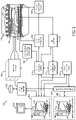
- FIG. 5 is a block diagram of an example MRI system that can implement the methods described in the present disclosure.
- MRI magnetic resonance imaging
- gradient coil settings e.g., gradient amplitudes, gradient slew rates
- PNS peripheral nerve stimulation
- a dielectric assembly is positioned adjacent a skin surface of the subject such that the dielectric assembly attenuates the local electric fields induced by the magnetic field gradients, and which would be likely to induce PNS when the dielectric assembly is not arranged adjacent the skin surface of the subject.
- the gradient coil settings can be increased above the threshold without inducing PNS in the subject.
- FIG. 1 illustrates an example plot of gradient coil settings (e.g., gradient amplitudes, gradient rise times) for a gradient coil. Points on the plot shown in FIG. 1 correspond to combinations of gradient amplitude and gradient rise time values.
- the area above line 12 in FIG. 1 corresponds to combinations of gradient coil settings that are not attainable due to hardware limitations. For example, areas above the line 12 correspond to gradient slew rates (which is the inverse of gradient rise time) that cannot be attained due to hardware limitations, gradient amplitudes that exceed that maximum gradient amplitude attainable with the gradient coil, or both. Thus, areas above the line generally correspond to gradient slew rate limited regimes and gradient amplitude limited regimes.
- FIG. 2 illustrates the desired effect of increasing PNS thresholds by arranging one or more dielectric assemblies adjacent a skin surface of a subject.
- the dielectric assembly is designed to attenuate local electric fields that would be likely to induce PNS in the subject and, as such, increases the PNS threshold from line 16 to line 18 as shown in FIG. 2 .
- combinations of gradient coil settings in region 20 can be safely used without inducing PNS in a subject. Without arranging the dielectric assembly adjacent the skin surface of the subject, gradient coil settings in region 20 would not be safe to use as they would be likely to induce PNS in at least some subsets of an average population.
- FIG. 3 an example of a dielectric assembly 30 arranged adjacent a skin surface 32 of a subject 34 is illustrated.
- the dielectric assembly 30 is implemented to attenuate local electrical fields in the subject 34 that would otherwise be likely to induce PNS.
- the dielectric assembly 30 can attenuate local electrical fields that are produced in response to magnetic gradient fields that were generated while operating a gradient coil using gradient coil settings above a conventional PNS threshold.
- the dielectric assembly 30 provides for safely operating the gradient coil using gradient coil setting above a conventional PNS threshold level. It will be appreciated that more than one such dielectric assemblies can be arranged adjacent the subject depending on the imaging task at hand.
- the dielectric assembly 30 can be arranged adjacent the skin surface 32 of the subject 34 by placing the dielectric assembly in direct contact with the skin surface 32 as shown in FIG. 3 , or can be arranged adjacent the skin surface 32 of the subject 34 by spacing the dielectric assembly 30 at a distance from the skin surface 32 , such that the dielectric assembly 30 is not in direct contact with the skin surface 32 .
- the dielectric assembly 30 can be arranged on a garment that is in direct contact with the skin surface 32 of the subject 34 .
- the dielectric assembly 30 can be provided to the subject 34 via an adhesive bandage such that the dielectric assembly 30 is arranged adjacent but not in direct contact with the skin surface 32 of the subject 34 .
- the dielectric assembly 30 can include pads, fabrics, or enclosures containing gels or liquids.
- gels or liquids may include gel-based dielectric materials, liquid water-based dielectric materials, and mixtures of particulates in a liquid or gel.
- dielectric materials that can be used include slurries or gels containing barium titanate (BaTiO 3 ) or calcium titanate (CaTiO 3 ).
- the dielectric material can include a dense aqueous suspension of barium titanate or calcium titanate, which can be formed into flexible pads, such as by heat sealing the suspension between two flexible substrates.
- the dielectric assembly 30 includes one or more dielectric materials or media.
- the dielectric assembly 30 may made to be rigid, while in other configurations the dielectric assembly 30 can be made to be flexible or otherwise conformable to the skin surface 32 of the subject 34 .
- the dielectric assembly 30 can include a thin fabric containing a dielectric material.
- the dielectric assembly 30 can be form a part of a garment to be worn by the subject.
- the dielectric assembly 30 could include flexible pads or fabrics coupled to a garment to be worn by the subject during an imaging session.
- the garment can be tight-fitting so as to place the dielectric assembly 30 into close proximity to the skin surface 32 of the subject 34 .
- the dielectric assembly 30 can include a rigid or flexible pad that can be positioned directly over specific regions of the subject 34 where peripheral nerve stimulation is likely or otherwise expected to occur.
- the dielectric assembly 30 can also include enclosures containing gels or liquids that include dielectric materials or media. Such enclosures can be rigid or flexible.
- the dielectric assembly 30 can include a gel pack containing a dielectric media, such as a hydrogel.
- the dielectric assembly can include a flexible or otherwise conformable enclosure (e.g., a plastic bag or the like) containing water.
- the dielectric assembly 30 can be sized, shaped, or otherwise dimensioned to optimize the reduction of PNS in a particular region of a subject.
- a PNS test protocol can be conducted to establish population-general limits for specific geometries of pads, or the like, placed on the subject's body.
- PNS may commonly occur in the arms, legs, or back, and different dielectric assemblies 30 can be constructed to be optimally sized, shaped, or otherwise dimensioned for these different anatomical regions.
- the dielectric assembly 30 can be incorporated into the patient table 36 .
- one or more dielectric assemblies 30 can be constructed as pads that are built into the patient table 36 to reduce PNS that may be induced in the subject's back.
- the dielectric assembly 30 can also be constructed as a pad or pillow on which the subject's head can rest.
- one or more dielectric assemblies 30 could be constructed to include tubes or sheaths into which the subject's arms or legs could be placed to reduce PNS that may be induced in the extremities.
- the dielectric assembly 30 can be constructed as a cap or mask that is placed over the subject's head of face.
- the method thus includes arranging one or more dielectric assemblies adjacent the skin surface of the subject, as indicated at step 402 .
- Examples of such dielectric assemblies are described above.
- a dielectric assembly can be arranged adjacent the skin surface of the subject by placing the dielectric assembly in direct contact of the skin surface, or it can be arranged adjacent to the skin surface without directly contact the skin surface.
- the dielectric assembly can be arranged adjacent the skin surface of the subject with a garment or other intervening object (even if just air) between the dielectric assembly and the skin surface of the subject.
- Arranging the one or more dielectric assemblies adjacent the skin surface of the subject preferably includes arranging the one or more dielectric assemblies proximate to regions in the subject that are likely to be affected by PNS.
- Example regions can include the extremities, the back, the neck, and the head.
- the method also includes setting gradient coil settings with a computer system, as indicated at step 404 .
- the gradient coil settings are selected based on the one or more dielectric assemblies arranged adjacent a skin surface of the subject.
- the gradient coil settings are selected to include a combination of settings (e.g., gradient amplitude, gradient rise time or slew rate) that would likely result in generating magnetic field gradients that would induce PNS in the subject, but for the one or more dielectric assemblies being arranged adjacent the skin surface of the subject.
- gradient coil settings that would otherwise not be safely implemented can be used.
- these gradient coil settings can result in generating stronger gradients, faster switching gradients, or both, which can improve imaging tasks such as diffusion imaging where stronger magnetic field gradients and faster gradient switching can be used to improve diffusion encoding.
- the gradient coil settings are selected, data are acquired from the subject with the MRI system, as recited in step 406 .
- the MRI system is operated to perform a pulse sequence that includes generating magnetic field gradients based on the selected gradient coil settings.
- One or more images of the subject can then be reconstructed from the acquired data, as indicated at step 408 .
- the MRI system 500 includes an operator workstation 502 that may include a display 504 , one or more input devices 506 (e.g., a keyboard, a mouse), and a processor 508 .
- the processor 508 may include a commercially available programmable machine running a commercially available operating system.
- the operator workstation 502 provides an operator interface that facilitates entering scan parameters into the MRI system 500 .
- the operator workstation 502 may be coupled to different servers, including, for example, a pulse sequence server 510 , a data acquisition server 512 , a data processing server 514 , and a data store server 516 .
- the operator workstation 502 and the servers 510 , 512 , 514 , and 516 may be connected via a communication system 540 , which may include wired or wireless network connections.
- the pulse sequence server 510 functions in response to instructions provided by the operator workstation 502 to operate a gradient system 518 and a radiofrequency (“RF”) system 520 .
- Gradient waveforms for performing a prescribed scan are produced and applied to the gradient system 518 , which then excites gradient coils in an assembly 522 to produce the magnetic field gradients G x , G y , and G z that are used for spatially encoding magnetic resonance signals.
- RF radiofrequency
- gradient waveforms can be defined by gradient coil settings (e.g., gradient amplitudes, gradient slew rates) selected based on the presence of one or more dielectric assemblies arranged adjacent the skin surface of the subject being imaged, or otherwise arranged proximate an anatomical region in which peripheral nerve stimulation is more likely to be induced in the subject.
- the gradient coil assembly 522 forms part of a magnet assembly 524 that includes a polarizing magnet 526 and an RF coil 528 , which may be a whole-body RF coil.
- RF waveforms are applied by the RF system 520 to the RF coil 528 , or a separate local coil to perform the prescribed magnetic resonance pulse sequence.
- Responsive magnetic resonance signals detected by the RF coil 528 , or a separate local coil are received by the RF system 520 .
- the responsive magnetic resonance signals may be amplified, demodulated, filtered, and digitized under direction of commands produced by the pulse sequence server 510 .
- the RF system 520 includes an RF transmitter for producing a wide variety of RF pulses used in MRI pulse sequences.
- the RF transmitter is responsive to the prescribed scan and direction from the pulse sequence server 510 to produce RF pulses of the desired frequency, phase, and pulse amplitude waveform.
- the generated RF pulses may be applied to the RF coil 528 or to one or more local coils or coil arrays.
- the RF system 520 also includes one or more RF receiver channels.
- An RF receiver channel includes an RF preamplifier that amplifies the magnetic resonance signal received by the RF coil 528 to which it is connected, and a detector that detects and digitizes the I and Q quadrature components of the received magnetic resonance signal.
- phase of the received magnetic resonance signal may also be determined according to the following relationship:
- the pulse sequence server 510 may receive patient data from a physiological acquisition controller 530 .
- the physiological acquisition controller 530 may receive signals from a number of different sensors connected to the patient, including electrocardiograph (“ECG”) signals from electrodes, or respiratory signals from a respiratory bellows or other respiratory monitoring devices. These signals may be used by the pulse sequence server 510 to synchronize, or “gate,” the performance of the scan with the subject's heart beat or respiration.
- ECG electrocardiograph
- the pulse sequence server 510 may also connect to a scan room interface circuit 532 that receives signals from various sensors associated with the condition of the patient and the magnet system. Through the scan room interface circuit 532 , a patient positioning system 534 can receive commands to move the patient to desired positions during the scan.
- the digitized magnetic resonance signal samples produced by the RF system 520 are received by the data acquisition server 512 .
- the data acquisition server 512 operates in response to instructions downloaded from the operator workstation 502 to receive the real-time magnetic resonance data and provide buffer storage, so that data is not lost by data overrun. In some scans, the data acquisition server 512 passes the acquired magnetic resonance data to the data processor server 514 . In scans that require information derived from acquired magnetic resonance data to control the further performance of the scan, the data acquisition server 512 may be programmed to produce such information and convey it to the pulse sequence server 510 . For example, during pre-scans, magnetic resonance data may be acquired and used to calibrate the pulse sequence performed by the pulse sequence server 510 .
- navigator signals may be acquired and used to adjust the operating parameters of the RF system 520 or the gradient system 518 , or to control the view order in which k-space is sampled.
- the data acquisition server 512 may also process magnetic resonance signals used to detect the arrival of a contrast agent in a magnetic resonance angiography (“MRA”) scan.
- MRA magnetic resonance angiography
- the data acquisition server 512 may acquire magnetic resonance data and processes it in real-time to produce information that is used to control the scan.
- the data processing server 514 receives magnetic resonance data from the data acquisition server 512 and processes the magnetic resonance data in accordance with instructions provided by the operator workstation 502 .
- processing may include, for example, reconstructing two-dimensional or three-dimensional images by performing a Fourier transformation of raw k-space data, performing other image reconstruction algorithms (e.g., iterative or backprojection reconstruction algorithms), applying filters to raw k-space data or to reconstructed images, generating functional magnetic resonance images, or calculating motion or flow images.
- Images reconstructed by the data processing server 514 are conveyed back to the operator workstation 502 for storage.
- Real-time images may be stored in a data base memory cache, from which they may be output to operator display 502 or a display 536 .
- Batch mode images or selected real time images may be stored in a host database on disc storage 538 .
- the data processing server 514 may notify the data store server 516 on the operator workstation 502 .
- the operator workstation 502 may be used by an operator to archive the images, produce films, or send the images via a network to other facilities.
- the MRI system 500 may also include one or more networked workstations 542 .
- a networked workstation 542 may include a display 544 , one or more input devices 546 (e.g., a keyboard, a mouse), and a processor 548 .
- the networked workstation 542 may be located within the same facility as the operator workstation 502 , or in a different facility, such as a different healthcare institution or clinic.
- the networked workstation 542 may gain remote access to the data processing server 514 or data store server 516 via the communication system 540 . Accordingly, multiple networked workstations 542 may have access to the data processing server 514 and the data store server 516 . In this manner, magnetic resonance data, reconstructed images, or other data may be exchanged between the data processing server 514 or the data store server 516 and the networked workstations 542 , such that the data or images may be remotely processed by a networked workstation 542 .
Landscapes
- Physics & Mathematics (AREA)
- General Physics & Mathematics (AREA)
- Condensed Matter Physics & Semiconductors (AREA)
- Life Sciences & Earth Sciences (AREA)
- Remote Sensing (AREA)
- Geology (AREA)
- Environmental & Geological Engineering (AREA)
- General Life Sciences & Earth Sciences (AREA)
- Engineering & Computer Science (AREA)
- Geophysics (AREA)
- High Energy & Nuclear Physics (AREA)
- Health & Medical Sciences (AREA)
- Epidemiology (AREA)
- Magnetic Resonance Imaging Apparatus (AREA)
Abstract
Description
M=√{square root over (I 2 +Q 2)} (1);
Claims (17)
Applications Claiming Priority (1)
| Application Number | Priority Date | Filing Date | Title |
|---|---|---|---|
| PCT/IB2016/056565 WO2018078428A1 (en) | 2016-10-31 | 2016-10-31 | System and method for reducing peripheral nerve stimulation at higher gradient amplitudes and faster gradient slew rates in magnetic resonance imaging |
Related Parent Applications (1)
| Application Number | Title | Priority Date | Filing Date |
|---|---|---|---|
| PCT/IB2016/056565 A-371-Of-International WO2018078428A1 (en) | 2016-10-31 | 2016-10-31 | System and method for reducing peripheral nerve stimulation at higher gradient amplitudes and faster gradient slew rates in magnetic resonance imaging |
Related Child Applications (1)
| Application Number | Title | Priority Date | Filing Date |
|---|---|---|---|
| US17/819,690 Continuation US11802923B2 (en) | 2016-10-31 | 2022-08-15 | System and method for reducing peripheral nerve stimulation at higher gradient amplitudes and faster gradient slew rates in magnetic resonance imaging |
Publications (2)
| Publication Number | Publication Date |
|---|---|
| US20200057124A1 US20200057124A1 (en) | 2020-02-20 |
| US11428760B2 true US11428760B2 (en) | 2022-08-30 |
Family
ID=62024422
Family Applications (2)
| Application Number | Title | Priority Date | Filing Date |
|---|---|---|---|
| US16/346,470 Active 2038-12-30 US11428760B2 (en) | 2016-10-31 | 2016-10-31 | System and method for reducing peripheral nerve stimulation at higher gradient amplitudes and faster gradient slew rates in magnetic resonance imaging |
| US17/819,690 Active US11802923B2 (en) | 2016-10-31 | 2022-08-15 | System and method for reducing peripheral nerve stimulation at higher gradient amplitudes and faster gradient slew rates in magnetic resonance imaging |
Family Applications After (1)
| Application Number | Title | Priority Date | Filing Date |
|---|---|---|---|
| US17/819,690 Active US11802923B2 (en) | 2016-10-31 | 2022-08-15 | System and method for reducing peripheral nerve stimulation at higher gradient amplitudes and faster gradient slew rates in magnetic resonance imaging |
Country Status (4)
| Country | Link |
|---|---|
| US (2) | US11428760B2 (en) |
| CA (1) | CA3042152A1 (en) |
| GB (1) | GB2573407B (en) |
| WO (1) | WO2018078428A1 (en) |
Families Citing this family (1)
| Publication number | Priority date | Publication date | Assignee | Title |
|---|---|---|---|---|
| US12268508B2 (en) * | 2019-12-10 | 2025-04-08 | The General Hospital Corporation | System for and method of rapid peripheral nerve stimulation assessment of gradient coils |
Citations (9)
| Publication number | Priority date | Publication date | Assignee | Title |
|---|---|---|---|---|
| US20040075434A1 (en) | 2002-10-16 | 2004-04-22 | Vavrek Robert Michael | Gradient coil apparatus for magnetic resonance imaging |
| US20040186375A1 (en) | 2003-03-21 | 2004-09-23 | Vavrek Robert M. | Rf coil embedded with homogeneity enhancing material |
| US20050068030A1 (en) | 2001-11-01 | 2005-03-31 | Peter Mansfield | Mri gradient coils with reduced neural stimulation |
| US7432713B2 (en) | 2006-06-02 | 2008-10-07 | Siemens Aktiengesellschaft | Dielectric element, and magnetic resonance imaging method using same |
| US7639011B2 (en) | 2007-03-12 | 2009-12-29 | Siemens Aktiengesellschaft | Field distribution correction element and method for generating a magnetic resonance exposure therewith |
| US20110316539A1 (en) | 2009-03-20 | 2011-12-29 | Koninklijke Philips Electronics N.V. | Antenna array comprising at least one dipole antenna for magnetic resonance imaging |
| US20120271150A1 (en) | 2011-04-22 | 2012-10-25 | Ehman Richard L | Flexible Passive Acoustic Driver for Magnetic Resonance Elastography |
| US20130184571A1 (en) * | 2012-01-12 | 2013-07-18 | Siemens Medical Solutions Usa, Inc. | Active system and method for imaging with an intra-patient probe |
| US20150011865A1 (en) | 2013-07-08 | 2015-01-08 | General Electric Company | Systems and methods for tracking imaging attenuators |
Family Cites Families (4)
| Publication number | Priority date | Publication date | Assignee | Title |
|---|---|---|---|---|
| SE8702160L (en) * | 1987-05-25 | 1988-11-26 | Hoek Instr Ab | STETOSCOPE BEFORE USING MAGNETIC RESONANCE DIAGNOSTICS M M |
| US7460027B2 (en) * | 2006-01-19 | 2008-12-02 | Progressive Engineering Technologies Corp. | Sensor cord array and method with conductive sensors for detecting activity on or around an object |
| US20080103576A1 (en) * | 2006-10-31 | 2008-05-01 | Medtronic, Inc. | Implantable medical elongated member including expandable fixation member |
| US8030920B2 (en) * | 2009-06-03 | 2011-10-04 | General Electric Company | Method and system for modifying pulse sequences |
-
2016
- 2016-10-31 GB GB1907615.7A patent/GB2573407B/en active Active
- 2016-10-31 US US16/346,470 patent/US11428760B2/en active Active
- 2016-10-31 CA CA3042152A patent/CA3042152A1/en active Pending
- 2016-10-31 WO PCT/IB2016/056565 patent/WO2018078428A1/en not_active Ceased
-
2022
- 2022-08-15 US US17/819,690 patent/US11802923B2/en active Active
Patent Citations (9)
| Publication number | Priority date | Publication date | Assignee | Title |
|---|---|---|---|---|
| US20050068030A1 (en) | 2001-11-01 | 2005-03-31 | Peter Mansfield | Mri gradient coils with reduced neural stimulation |
| US20040075434A1 (en) | 2002-10-16 | 2004-04-22 | Vavrek Robert Michael | Gradient coil apparatus for magnetic resonance imaging |
| US20040186375A1 (en) | 2003-03-21 | 2004-09-23 | Vavrek Robert M. | Rf coil embedded with homogeneity enhancing material |
| US7432713B2 (en) | 2006-06-02 | 2008-10-07 | Siemens Aktiengesellschaft | Dielectric element, and magnetic resonance imaging method using same |
| US7639011B2 (en) | 2007-03-12 | 2009-12-29 | Siemens Aktiengesellschaft | Field distribution correction element and method for generating a magnetic resonance exposure therewith |
| US20110316539A1 (en) | 2009-03-20 | 2011-12-29 | Koninklijke Philips Electronics N.V. | Antenna array comprising at least one dipole antenna for magnetic resonance imaging |
| US20120271150A1 (en) | 2011-04-22 | 2012-10-25 | Ehman Richard L | Flexible Passive Acoustic Driver for Magnetic Resonance Elastography |
| US20130184571A1 (en) * | 2012-01-12 | 2013-07-18 | Siemens Medical Solutions Usa, Inc. | Active system and method for imaging with an intra-patient probe |
| US20150011865A1 (en) | 2013-07-08 | 2015-01-08 | General Electric Company | Systems and methods for tracking imaging attenuators |
Non-Patent Citations (1)
| Title |
|---|
| International Search Report and Written Opinion for PCT/IB2016/056565, dated Mar. 23, 2017, 13 pages. |
Also Published As
| Publication number | Publication date |
|---|---|
| US20220390535A1 (en) | 2022-12-08 |
| US20200057124A1 (en) | 2020-02-20 |
| WO2018078428A1 (en) | 2018-05-03 |
| GB2573407A8 (en) | 2019-11-27 |
| US11802923B2 (en) | 2023-10-31 |
| GB201907615D0 (en) | 2019-07-10 |
| GB2573407A (en) | 2019-11-06 |
| CA3042152A1 (en) | 2018-05-03 |
| GB2573407B (en) | 2022-07-13 |
Similar Documents
| Publication | Publication Date | Title |
|---|---|---|
| US20150115956A1 (en) | System and method for quiet magnetic resonance imaging | |
| Woo et al. | Magnetic resonance electrical impedance tomography (MREIT) for high-resolution conductivity imaging | |
| CN102908144B (en) | Magnetic resonance imaging for treatment plan | |
| CN102469952B (en) | Apparatus and method for determining at least one electromagnetic quantity | |
| CN103654781B (en) | Check that object carries out method and the magnetic resonance equipment of nuclear magnetic resonance by excitation | |
| CN102497810B (en) | Apparatus and method for influencing and/or detecting magnetic particles in a field of view | |
| EP2475298B1 (en) | Apparatus and method for influencing and/or detecting magnetic particles | |
| KR101775028B1 (en) | Magnetic resonance imaging apparatus and method of obtaining magnetic resonance image | |
| JP2019177189A (en) | System and method for low-magnetic field, multi-channel imaging | |
| JP3672976B2 (en) | Magnetic resonance imaging system | |
| WO2004026100A2 (en) | Using magnetic resonance imaging to directly map neuronal activity | |
| US11872025B2 (en) | System and method for magnetic resonance elastography | |
| RU2550660C2 (en) | Device and method of non-invasive intracardial electrocardiography with formation of image with application of magnetic particles | |
| US11802923B2 (en) | System and method for reducing peripheral nerve stimulation at higher gradient amplitudes and faster gradient slew rates in magnetic resonance imaging | |
| CN103356185A (en) | Method and magnetic resonance equipment for functional magnetic resonance imaging of predetermined volume segment of brain of living examination subject | |
| WO2021030466A1 (en) | Simultaneous multi-orientation magnetic resonance imaging | |
| Mamatjan | Imaging of hemorrhagic stroke in magnetic induction tomography: An in vitro study | |
| US20180085024A1 (en) | System and method for magnetic resonance angiography using hyperpolarized fluid | |
| JP5418952B1 (en) | Brain activity measuring device and brain activity measuring method | |
| CN219594618U (en) | Electrocardiogram apparatus and magnetic resonance apparatus configured for use in conjunction with magnetic resonance apparatus | |
| TR202007444A1 (en) | AN EQUIPMENT THAT PROVIDES BOTH MAGNETIC PARTICLE IMAGING AND MAGNETIC RESONANCE IMAGING AND A DEVICE CONTAINING THIS EQUIPMENT | |
| US12066511B2 (en) | Method for designing electromagnetic coils with explicit peripheral nerve stimulation constraint based on an oracle penalty | |
| WO2016156340A1 (en) | Apparatus and method for influencing and/or detecting magnetic particles | |
| JP2021115014A (en) | Radiation therapy apparatus, medical image processing apparatus, and medical image processing method | |
| US10408904B2 (en) | MRI using a modified DIXON sequence with reduction of fold-over artifacts |
Legal Events
| Date | Code | Title | Description |
|---|---|---|---|
| FEPP | Fee payment procedure |
Free format text: ENTITY STATUS SET TO UNDISCOUNTED (ORIGINAL EVENT CODE: BIG.); ENTITY STATUS OF PATENT OWNER: SMALL ENTITY |
|
| STPP | Information on status: patent application and granting procedure in general |
Free format text: DOCKETED NEW CASE - READY FOR EXAMINATION |
|
| AS | Assignment |
Owner name: SYNAPTIVE MEDICAL (BARBADOS) INC., BARBADOS Free format text: ASSIGNMENT OF ASSIGNORS INTEREST;ASSIGNORS:HARRIS, CHAD TYLER;HANDLER, WILLIAM BRADFIELD;BINDSEIL, GERON ANDRE;SIGNING DATES FROM 20170201 TO 20170207;REEL/FRAME:054195/0185 |
|
| AS | Assignment |
Owner name: SYNAPTIVE MEDICAL INC., CANADA Free format text: ASSIGNMENT OF ASSIGNORS INTEREST;ASSIGNOR:SYNAPTIVE MEDICAL (BARBADOS) INC.;REEL/FRAME:054251/0139 Effective date: 20200902 |
|
| FEPP | Fee payment procedure |
Free format text: ENTITY STATUS SET TO SMALL (ORIGINAL EVENT CODE: SMAL); ENTITY STATUS OF PATENT OWNER: SMALL ENTITY |
|
| AS | Assignment |
Owner name: ESPRESSO CAPITAL LTD., CANADA Free format text: SECURITY INTEREST;ASSIGNOR:SYNAPTIVE MEDICAL INC.;REEL/FRAME:054922/0791 Effective date: 20201223 |
|
| STPP | Information on status: patent application and granting procedure in general |
Free format text: NOTICE OF ALLOWANCE MAILED -- APPLICATION RECEIVED IN OFFICE OF PUBLICATIONS |
|
| STPP | Information on status: patent application and granting procedure in general |
Free format text: PUBLICATIONS -- ISSUE FEE PAYMENT VERIFIED |
|
| STCF | Information on status: patent grant |
Free format text: PATENTED CASE |