US11423715B1 - Vehicle diagnostic device - Google Patents
Vehicle diagnostic device Download PDFInfo
- Publication number
- US11423715B1 US11423715B1 US16/701,967 US201916701967A US11423715B1 US 11423715 B1 US11423715 B1 US 11423715B1 US 201916701967 A US201916701967 A US 201916701967A US 11423715 B1 US11423715 B1 US 11423715B1
- Authority
- US
- United States
- Prior art keywords
- circuit board
- housing
- cable
- vehicle
- computer
- Prior art date
- Legal status (The legal status is an assumption and is not a legal conclusion. Google has not performed a legal analysis and makes no representation as to the accuracy of the status listed.)
- Active, expires
Links
Images


Classifications
-
- G—PHYSICS
- G07—CHECKING-DEVICES
- G07C—TIME OR ATTENDANCE REGISTERS; REGISTERING OR INDICATING THE WORKING OF MACHINES; GENERATING RANDOM NUMBERS; VOTING OR LOTTERY APPARATUS; ARRANGEMENTS, SYSTEMS OR APPARATUS FOR CHECKING NOT PROVIDED FOR ELSEWHERE
- G07C5/00—Registering or indicating the working of vehicles
- G07C5/008—Registering or indicating the working of vehicles communicating information to a remotely located station
-
- G—PHYSICS
- G06—COMPUTING OR CALCULATING; COUNTING
- G06F—ELECTRIC DIGITAL DATA PROCESSING
- G06F1/00—Details not covered by groups G06F3/00 - G06F13/00 and G06F21/00
- G06F1/16—Constructional details or arrangements
- G06F1/1613—Constructional details or arrangements for portable computers
-
- G—PHYSICS
- G06—COMPUTING OR CALCULATING; COUNTING
- G06F—ELECTRIC DIGITAL DATA PROCESSING
- G06F1/00—Details not covered by groups G06F3/00 - G06F13/00 and G06F21/00
- G06F1/16—Constructional details or arrangements
- G06F1/1613—Constructional details or arrangements for portable computers
- G06F1/1626—Constructional details or arrangements for portable computers with a single-body enclosure integrating a flat display, e.g. Personal Digital Assistants [PDAs]
-
- G—PHYSICS
- G06—COMPUTING OR CALCULATING; COUNTING
- G06F—ELECTRIC DIGITAL DATA PROCESSING
- G06F1/00—Details not covered by groups G06F3/00 - G06F13/00 and G06F21/00
- G06F1/16—Constructional details or arrangements
- G06F1/1613—Constructional details or arrangements for portable computers
- G06F1/1633—Constructional details or arrangements of portable computers not specific to the type of enclosures covered by groups G06F1/1615 - G06F1/1626
- G06F1/1656—Details related to functional adaptations of the enclosure, e.g. to provide protection against EMI, shock, water, or to host detachable peripherals like a mouse or removable expansions units like PCMCIA cards, or to provide access to internal components for maintenance or to removable storage supports like CDs or DVDs, or to mechanically mount accessories
- G06F1/166—Details related to functional adaptations of the enclosure, e.g. to provide protection against EMI, shock, water, or to host detachable peripherals like a mouse or removable expansions units like PCMCIA cards, or to provide access to internal components for maintenance or to removable storage supports like CDs or DVDs, or to mechanically mount accessories related to integrated arrangements for adjusting the position of the main body with respect to the supporting surface, e.g. legs for adjusting the tilt angle
-
- G—PHYSICS
- G07—CHECKING-DEVICES
- G07C—TIME OR ATTENDANCE REGISTERS; REGISTERING OR INDICATING THE WORKING OF MACHINES; GENERATING RANDOM NUMBERS; VOTING OR LOTTERY APPARATUS; ARRANGEMENTS, SYSTEMS OR APPARATUS FOR CHECKING NOT PROVIDED FOR ELSEWHERE
- G07C5/00—Registering or indicating the working of vehicles
- G07C5/08—Registering or indicating performance data other than driving, working, idle, or waiting time, with or without registering driving, working, idle or waiting time
- G07C5/0808—Diagnosing performance data
-
- G—PHYSICS
- G06—COMPUTING OR CALCULATING; COUNTING
- G06F—ELECTRIC DIGITAL DATA PROCESSING
- G06F2200/00—Indexing scheme relating to G06F1/04 - G06F1/32
- G06F2200/16—Indexing scheme relating to G06F1/16 - G06F1/18
- G06F2200/163—Indexing scheme relating to constructional details of the computer
- G06F2200/1633—Protecting arrangement for the entire housing of the computer
-
- G—PHYSICS
- G06—COMPUTING OR CALCULATING; COUNTING
- G06F—ELECTRIC DIGITAL DATA PROCESSING
- G06F2213/00—Indexing scheme relating to interconnection of, or transfer of information or other signals between, memories, input/output devices or central processing units
- G06F2213/0042—Universal serial bus [USB]
-
- G—PHYSICS
- G07—CHECKING-DEVICES
- G07C—TIME OR ATTENDANCE REGISTERS; REGISTERING OR INDICATING THE WORKING OF MACHINES; GENERATING RANDOM NUMBERS; VOTING OR LOTTERY APPARATUS; ARRANGEMENTS, SYSTEMS OR APPARATUS FOR CHECKING NOT PROVIDED FOR ELSEWHERE
- G07C2205/00—Indexing scheme relating to group G07C5/00
- G07C2205/02—Indexing scheme relating to group G07C5/00 using a vehicle scan tool
Definitions
- the present invention is directed to a vehicle diagnostic device, and in particular a portable integrated vehicle diagnostic tool including a computer and a separate J2534 pass-thru computer module.
- Vehicle diagnostic systems employing diagnostic scan devices or tools are used in automotive repair facilities to diagnose and repair computer-based vehicle systems, where vehicles may have differing computer-based systems depending on the configuration and options installed on the vehicle.
- Vehicle diagnostic scan systems may include or use one or more diagnostic software scanning programs or applications, such as applications developed by an original equipment automotive manufacturer (“OEM”), or an aftermarket diagnostic company.
- OEM original equipment automotive manufacturer
- the diagnostic software scanning programs are used to diagnose the electronic system of a vehicle.
- Repair facilities must diagnose the electronic computer systems of vehicles, including scanning and reprogramming electronic control units of the vehicle electronic computer systems as needed for software updates and/or repairs.
- Repair facilities may obtain equipment so as to be able to perform such diagnostic operations, including by way of pass through interface devices that operate according to the SAE J2534 standard, and local computers utilizing diagnostic software applications for use in scanning, diagnosing and reprogramming the vehicle.
- Repair facilities may also obtain alternative equipment whereby diagnostic and reprograming operations are facilitated via remote diagnostic computer systems utilizing diagnostic software applications, in which case the vehicle will be connected with electronic equipment to facilitate the transmission of vehicle data via the Internet.
- a vehicle diagnostic device for diagnosing, scanning and programming an electrical system of a vehicle.
- a vehicle diagnostic device includes a housing, a computer having a screen and a computer processor, with the computer disposed within the housing and the housing including a screen opening for the computer screen.
- a circuit board is additionally disposed within the housing, with the circuit board including a circuit board processor and a multi-pin connector and the housing including an aperture for the connector.
- a cable disposed within the housing connects the computer and circuit board for communications there between.
- the circuit board is configured to receive vehicle data signals from an electrical system of a vehicle via the connector and convert the vehicle data signals for transmission to the computer via the cable, and wherein the computer is configured to transmit signals to the circuit board via the cable for conversion by the circuit board to vehicle data signals for transmission via the connector to the electrical system of the vehicle.
- the circuit board is configured to operate as a SAE J2534 pass-thru device
- the computer is a tablet computer with a touchscreen.
- the cable is a USB cable connected to USB connectors on the computer and circuit board.
- the vehicle diagnostic device is connectable to the electrical system of the vehicle by a communication cable.
- the housing includes first and second housing members that are connected together to contain the computer, circuit board and cable within the housing.
- the first housing member may include the screen opening with the computer being mounted to the first housing member.
- the second housing member may include the aperture with the circuit board being mounted to the second housing member.
- the housing may be further configured to include one or more external handles.
- the computer is operable to wirelessly transmit and receive signals from a remote diagnostic computer.
- the vehicle diagnostic device of the present invention provides a convenient and portable integrated vehicle diagnostic tool for use in diagnosing, scanning and programming an electrical system of a vehicle.
- the utilization of a separate J2534 circuit board enables the vehicle diagnostic tool to be readily used with a wide variety of makes and models of vehicles, with the tablet computer providing an easy to use and convenient operator interface.
- FIG. 1 is a schematic illustration of a vehicle diagnostic device in accordance with the present invention shown in use with a vehicle at a repair facility;
- FIG. 2 is a front perspective view of a vehicle diagnostic device in accordance with the present invention.
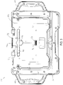
- FIG. 3 is a rear plan view of the vehicle diagnostic device of FIG. 2 ;
- FIG. 4 is a right side edge view of the vehicle diagnostic device of FIG. 2 ;
- FIG. 5 is a rear end view of the vehicle diagnostic device of FIG. 2 ;
- FIG. 6A is a rear exploded perspective view of the vehicle diagnostic device of FIG. 2 ;
- FIG. 6B is a front exploded perspective view of the vehicle diagnostic device of FIG. 2 ;
- FIG. 7A is an internal plan view of the front half of the vehicle diagnostic device of FIG. 2 ;
- FIG. 7B is an internal plan view of the back half of the vehicle diagnostic device of FIG. 2 ;
- FIG. 8 is a perspective view of a docking station for the vehicle diagnostic device of FIG. 2 ;
- FIG. 9 is a perspective view of the vehicle diagnostic device of FIG. 2 connected to the docking station of FIG. 8 .
- a vehicle diagnostic device or tool 20 is shown that is used for the diagnosing, scanning and programming the electrical system 23 of a vehicle 22 by an operator 24 at a repair facility 25 .
- Diagnostic tool 20 includes a housing 30 that contains a computer 32 and a separate computer module or circuit board 34 , where a computer cable 36 ( FIGS. 7A and 7B ) is connected to both computer 32 and circuit board 34 to enable communication there between.
- computer 32 is a tablet computer and circuit board 34 is configured to operate in accordance with Society of Automotive Engineers (SAE) J2534 standard as a conventional J2534 pass-thru device.
- SAE Society of Automotive Engineers
- Operator 24 is able to diagnose, scan and program electronic control units (ECUs) of the electrical system 23 using diagnostic tool 20 by connecting diagnostic tool 20 to the an on-board diagnostic (“OBD”) diagnostic port 38 of vehicle 22 using cable 40 , with diagnostic tool 20 , in turn, either including diagnostic software applications thereon or being connected to a remote diagnostic computer 42 by way of an Internet connection 44 , with the remote diagnostic computer 44 having or utilizing one or more diagnostic software applications 46 a , 46 b , 46 c for the particular make and model of vehicle and being operated by a remote technician 48 .
- OBD on-board diagnostic
- housing 30 in the illustrated embodiment comprises a front housing member 50 and a rear housing member 52 that are connected together in clam shell arrangement.
- Housing member 50 includes left and right handle portions 51 a , 51 b and housing member 52 includes left and right handle portions 53 a , 53 b ( FIGS. 6A and 6B ).
- housing 30 When assembled, housing 30 thus includes left and right handles 54 , 56 , respectively.
- Diagnostic tool 20 is portable, with handles 54 , 56 thus aiding in the portability of diagnostic tool 20 , where in the illustrated embodiment diagnostic tool is approximately eight inches tall, by twelve inches wide and several inches thick.
- Housing members 50 , 52 in the illustrated embodiment are constructed as molded components, with housing 30 additionally including in the illustrated embodiment various elastomeric pads disposed thereon, such as for aid in gripping and/or cushioning of tool 20 .
- Front housing member 50 includes a central opening 58 whereby the screen 60 of tablet computer 32 is accessible. Housing member 50 further includes an internal perimeter frame 62 disposed about opening 58 to which in the illustrated embodiment mounts 33 of tablet are secured via fasteners to retain tablet 32 to housing member 50 , with a gasket 66 positioned there between. Front housing member 50 further supports a power button 68 for turning diagnostic tool 20 on and off.
- Rear housing member 52 includes an internal receptacle or cavity 70 for receiving the J2534 circuit board 34 , where in the illustrated embodiment circuit board 34 is retained to housing member 52 by fasteners.
- a top or rear edge 71 of housing member 52 includes an aperture 72 through which a connector 74 mounted to the circuit board 34 is exposed.
- a pivoting stand 76 is secured to a rear or back surface 76 .
- a rear receptacle or cavity 78 is also included on back surface 76 for removably retaining a stylus 80 that is selectively retained within cavity 78 by an interference fit.
- Rear housing member 52 additionally supports rechargeable batteries 82 ( FIG. 6B ).
- tablet computer 32 is a substantially conventional tablet computer with a touchscreen 60 and an outer case 84 , as well as an internal circuit board supporting hardware and software, including one or more internal processors, such as an internal processor 85 disposed within case 84 ( FIG. 6A ).
- Computer 32 further includes an operating system and an internal wireless Internet module or chip 87 , such as for WiFi communications ( FIG. 6A ).
- Tablet computer 32 also includes software for guiding an operator 24 through operational steps for diagnosing vehicle 22 , with such diagnosing including scanning and/or reprogramming of the electrical system 23 of vehicle 22 .
- touchscreen 60 is accessible via opening 58 .
- opening 58 is sized so as to be smaller than the case 84 of tablet computer 32 .
- tablet 32 is provided with a connector or port 86 for connecting with one end 35 ( FIGS. 6B and 7A ) of cable 36 for communication there between with J2534 circuit board 34 .
- J2534 circuit board 34 in turn, includes a connector or port 88 for receiving the opposite end 37 ( FIGS. 6A, 6B and 7B ) of cable 36 .
- cable 36 is a USB cable, with ends 35 , 37 configured as USB connectors.
- Circuit board 34 also includes multiple hardware components, including at least one processor 90 , as well as software.
- Circuit board 34 additionally includes the multi-pin connector or port 72 for connecting with cable 40 to communicate with electrical system 23 of vehicle 22 .
- rear housing member 52 includes an opening 74 through which port 72 is accessible.
- J2534 circuit board 34 is configured to operate in accordance with the SAE J2534 standard as a conventional J2534 pass-thru device.
- circuit board 34 additionally includes a database of vehicle protocols in local memory on circuit board 34 that allow communication with the ECUs of various makes and models of vehicles.
- circuit board 34 is configured to receive vehicle data signals via cable 40 and port 92 and, based on a determined protocol of the vehicle data signals, convert the vehicle data signals to a J2534 protocol message for transmission to tablet computer 32 .
- circuit board 34 is operable to receive J2534 protocol messages from tablet computer 32 and convert such messages to vehicle data signals for delivery to the electrical system 23 of vehicle 22 via port 72 and cable 30 .
- a J2534 protocol message comprises a message that is formatted into another protocol from the protocol of the vehicle data signals for use by the tablet computer 32 . That is, different vehicle makes and models utilize differing protocols within their respective electrical systems, with the J2534 pass-thru device operating to convert those protocols into a protocol for use by the tablet computer 32 .
- Tablet computer 32 may include diagnostic software applications for use in diagnosing electrical system 23 , including by way of scanning and programming ECUs of the electrical system 23 .
- tablet computer 32 may transmit J2534 protocol messages to remote diagnostic computer 42 , with remote diagnostic computer 42 including diagnostic software applications 46 a - 46 c for use with different makes and models of vehicles 22 to diagnose, scan and reprogram electrical system 23 of vehicle 22 .
- tablet computer 32 may communicate with remote diagnostic computer 42 by way of an Internet connection 44 , with tablet computer 32 transmitting the J2534 protocol messages via a standard/conventional Internet transmittal protocol, such as via TCP/IP or UDP or the like.
- signals received by tablet computer 32 from remote diagnostic computer 42 may in turn be sent as J2534 protocol messages to circuit board 34 , with circuit board 34 in turn converting the J2534 protocol messages to the appropriate vehicle data signals associated with the protocol of the electrical system 23 of the vehicle 22 under test and transmit the vehicle data signals to the electrical system 23 in conventional manner via port 92 and cable 40 connected with OBD port 38 .
- rear housing member 52 includes an additional aperture 96 for exposing an internal connector 98 that enables recharging of batteries 82 and/or powering of vehicle diagnostic tool 20 separately from batteries 82 .
- a docking station 100 may be provided for use with diagnostic tool 20 , wherein docking station 100 includes a ledge 102 and an angled support surface 104 for supporting diagnostic tool 20 . Docking station 100 further includes a power connector 106 that mates with internal connector 98 when diagnostic tool 20 is supported by docking station whereby power may be supplied to diagnostic tool 20 via docking station 100 .
- a vehicle diagnostic device or tool may be provided within the scope of the present invention.
- alternatively configured and arranged housings may be used with vehicle diagnostic devices in accordance with the present invention, including with an alternatively configured handle or handles, or without handles.
- the vehicle diagnostic device in accordance with the present invention may be configured for use with OBD 1 and/or OBD 2 systems. Further changes and modifications in the specifically described embodiments can be carried out without departing from the principles of the present invention which is intended to be limited only by the scope of the appended claims, as interpreted according to the principles of patent law including the doctrine of equivalents.
Landscapes
- Engineering & Computer Science (AREA)
- Physics & Mathematics (AREA)
- General Physics & Mathematics (AREA)
- Theoretical Computer Science (AREA)
- Computer Hardware Design (AREA)
- General Engineering & Computer Science (AREA)
- Human Computer Interaction (AREA)
- Vehicle Cleaning, Maintenance, Repair, Refitting, And Outriggers (AREA)
Abstract
A vehicle diagnostic device for use in diagnosing, scanning and programming an electrical system of a vehicle having a housing, a computer with a screen disposed within the housing with the screen being disposed at an opening of the housing. The vehicle diagnostic device further includes a circuit board configured to operate as a SAE J2534 pass-thru device and disposed within the housing, with the circuit board including a multi-pin connector disposed at an aperture of the housing. A cable connects the computer and circuit board for communications there between. The circuit board is configured to receive vehicle data signals from a vehicle via the connector and convert the vehicle data signals for transmission to the computer via the cable. The computer is further configured to transmit signals to the circuit board via the cable for conversion by the circuit board to vehicle data signals for transmission via the connector to the vehicle.
Description
The present invention is directed to a vehicle diagnostic device, and in particular a portable integrated vehicle diagnostic tool including a computer and a separate J2534 pass-thru computer module.
In automotive repair garages, many of the tools used to diagnose and repair cars have transitioned to computer-based systems. Vehicle diagnostic systems employing diagnostic scan devices or tools are used in automotive repair facilities to diagnose and repair computer-based vehicle systems, where vehicles may have differing computer-based systems depending on the configuration and options installed on the vehicle. Vehicle diagnostic scan systems may include or use one or more diagnostic software scanning programs or applications, such as applications developed by an original equipment automotive manufacturer (“OEM”), or an aftermarket diagnostic company. The diagnostic software scanning programs are used to diagnose the electronic system of a vehicle.
Repair facilities must diagnose the electronic computer systems of vehicles, including scanning and reprogramming electronic control units of the vehicle electronic computer systems as needed for software updates and/or repairs. Repair facilities may obtain equipment so as to be able to perform such diagnostic operations, including by way of pass through interface devices that operate according to the SAE J2534 standard, and local computers utilizing diagnostic software applications for use in scanning, diagnosing and reprogramming the vehicle. Repair facilities may also obtain alternative equipment whereby diagnostic and reprograming operations are facilitated via remote diagnostic computer systems utilizing diagnostic software applications, in which case the vehicle will be connected with electronic equipment to facilitate the transmission of vehicle data via the Internet.
The present invention provides a vehicle diagnostic device for diagnosing, scanning and programming an electrical system of a vehicle. According to an aspect of the present invention, a vehicle diagnostic device includes a housing, a computer having a screen and a computer processor, with the computer disposed within the housing and the housing including a screen opening for the computer screen. A circuit board is additionally disposed within the housing, with the circuit board including a circuit board processor and a multi-pin connector and the housing including an aperture for the connector. A cable disposed within the housing connects the computer and circuit board for communications there between. The circuit board is configured to receive vehicle data signals from an electrical system of a vehicle via the connector and convert the vehicle data signals for transmission to the computer via the cable, and wherein the computer is configured to transmit signals to the circuit board via the cable for conversion by the circuit board to vehicle data signals for transmission via the connector to the electrical system of the vehicle.
According to particular embodiments of the vehicle diagnostic device, the circuit board is configured to operate as a SAE J2534 pass-thru device, and the computer is a tablet computer with a touchscreen. Still further, the cable is a USB cable connected to USB connectors on the computer and circuit board. The vehicle diagnostic device is connectable to the electrical system of the vehicle by a communication cable.
In a further particular embodiment, the housing includes first and second housing members that are connected together to contain the computer, circuit board and cable within the housing. The first housing member may include the screen opening with the computer being mounted to the first housing member. Still further, the second housing member may include the aperture with the circuit board being mounted to the second housing member. The housing may be further configured to include one or more external handles.
According to a further particular embodiment the computer is operable to wirelessly transmit and receive signals from a remote diagnostic computer.
The vehicle diagnostic device of the present invention provides a convenient and portable integrated vehicle diagnostic tool for use in diagnosing, scanning and programming an electrical system of a vehicle. The utilization of a separate J2534 circuit board enables the vehicle diagnostic tool to be readily used with a wide variety of makes and models of vehicles, with the tablet computer providing an easy to use and convenient operator interface. These and other objects, advantages, purposes and features of this invention will become apparent upon review of the following specification in conjunction with the drawings.
The present invention will now be described with reference to the accompanying figures, wherein the numbered elements in the following written description correspond to like-numbered elements in the figures.
With initial reference to FIGS. 1, 2 and 6A , a vehicle diagnostic device or tool 20 is shown that is used for the diagnosing, scanning and programming the electrical system 23 of a vehicle 22 by an operator 24 at a repair facility 25. Diagnostic tool 20 includes a housing 30 that contains a computer 32 and a separate computer module or circuit board 34, where a computer cable 36 (FIGS. 7A and 7B ) is connected to both computer 32 and circuit board 34 to enable communication there between. In the illustrated embodiment, computer 32 is a tablet computer and circuit board 34 is configured to operate in accordance with Society of Automotive Engineers (SAE) J2534 standard as a conventional J2534 pass-thru device. Operator 24 is able to diagnose, scan and program electronic control units (ECUs) of the electrical system 23 using diagnostic tool 20 by connecting diagnostic tool 20 to the an on-board diagnostic (“OBD”) diagnostic port 38 of vehicle 22 using cable 40, with diagnostic tool 20, in turn, either including diagnostic software applications thereon or being connected to a remote diagnostic computer 42 by way of an Internet connection 44, with the remote diagnostic computer 44 having or utilizing one or more diagnostic software applications 46 a, 46 b, 46 c for the particular make and model of vehicle and being operated by a remote technician 48.
With reference now to FIGS. 2-7B , housing 30 in the illustrated embodiment comprises a front housing member 50 and a rear housing member 52 that are connected together in clam shell arrangement. Housing member 50 includes left and right handle portions 51 a, 51 b and housing member 52 includes left and right handle portions 53 a, 53 b (FIGS. 6A and 6B ). When assembled, housing 30 thus includes left and right handles 54, 56, respectively. Diagnostic tool 20 is portable, with handles 54, 56 thus aiding in the portability of diagnostic tool 20, where in the illustrated embodiment diagnostic tool is approximately eight inches tall, by twelve inches wide and several inches thick. Housing members 50, 52 in the illustrated embodiment are constructed as molded components, with housing 30 additionally including in the illustrated embodiment various elastomeric pads disposed thereon, such as for aid in gripping and/or cushioning of tool 20.
In the illustrated embodiment tablet computer 32 is a substantially conventional tablet computer with a touchscreen 60 and an outer case 84, as well as an internal circuit board supporting hardware and software, including one or more internal processors, such as an internal processor 85 disposed within case 84 (FIG. 6A ). Computer 32 further includes an operating system and an internal wireless Internet module or chip 87, such as for WiFi communications (FIG. 6A ). Tablet computer 32 also includes software for guiding an operator 24 through operational steps for diagnosing vehicle 22, with such diagnosing including scanning and/or reprogramming of the electrical system 23 of vehicle 22. When mounted within housing 30, and in particular when mounted to front housing member 50, touchscreen 60 is accessible via opening 58. In the illustrated embodiment opening 58 is sized so as to be smaller than the case 84 of tablet computer 32. As shown in FIGS. 6A and 6B , tablet 32 is provided with a connector or port 86 for connecting with one end 35 (FIGS. 6B and 7A ) of cable 36 for communication there between with J2534 circuit board 34.
As noted, J2534 circuit board 34 is configured to operate in accordance with the SAE J2534 standard as a conventional J2534 pass-thru device. As such, circuit board 34 additionally includes a database of vehicle protocols in local memory on circuit board 34 that allow communication with the ECUs of various makes and models of vehicles. Still further, circuit board 34 is configured to receive vehicle data signals via cable 40 and port 92 and, based on a determined protocol of the vehicle data signals, convert the vehicle data signals to a J2534 protocol message for transmission to tablet computer 32. Likewise, circuit board 34 is operable to receive J2534 protocol messages from tablet computer 32 and convert such messages to vehicle data signals for delivery to the electrical system 23 of vehicle 22 via port 72 and cable 30. It should be appreciated that a J2534 protocol message comprises a message that is formatted into another protocol from the protocol of the vehicle data signals for use by the tablet computer 32. That is, different vehicle makes and models utilize differing protocols within their respective electrical systems, with the J2534 pass-thru device operating to convert those protocols into a protocol for use by the tablet computer 32.
As understood from FIGS. 3, 6A and 6B , rear housing member 52 includes an additional aperture 96 for exposing an internal connector 98 that enables recharging of batteries 82 and/or powering of vehicle diagnostic tool 20 separately from batteries 82. As understood from FIGS. 8 and 9 , a docking station 100 may be provided for use with diagnostic tool 20, wherein docking station 100 includes a ledge 102 and an angled support surface 104 for supporting diagnostic tool 20. Docking station 100 further includes a power connector 106 that mates with internal connector 98 when diagnostic tool 20 is supported by docking station whereby power may be supplied to diagnostic tool 20 via docking station 100.
It should be appreciated that various configurations, constructions and arrangements of a vehicle diagnostic device or tool may be provided within the scope of the present invention. For example, alternatively configured and arranged housings may be used with vehicle diagnostic devices in accordance with the present invention, including with an alternatively configured handle or handles, or without handles. It should also be appreciated that the vehicle diagnostic device in accordance with the present invention may be configured for use with OBD 1 and/or OBD 2 systems. Further changes and modifications in the specifically described embodiments can be carried out without departing from the principles of the present invention which is intended to be limited only by the scope of the appended claims, as interpreted according to the principles of patent law including the doctrine of equivalents.
Claims (20)
1. A vehicle diagnostic device for use in diagnosing, scanning and programming an electrical system of a vehicle, said vehicle diagnostic device comprising:
a housing having a front and a back;
a computer having a case, a screen joined with said case, a first cable connector, and a computer processor disposed within said case, wherein said computer is disposed within said housing with said housing including a screen opening at said front of said housing and said screen being disposed at said screen opening;
a circuit board disposed within said housing between said computer and said back of said housing, said circuit board including a circuit board processor, a second cable connector, and a multi-pin connector with said housing including an aperture and said multi-pin connector being disposed at said aperture;
a cable disposed within said housing and connecting said computer and said circuit board for communications there between with said cable being connected to said first cable connector and to said second cable connector;
wherein said circuit board is configured to receive vehicle data signals from an electrical system of a vehicle via said multi-pin connector and convert said vehicle data signals for transmission to said computer via said cable, and wherein said computer is configured to transmit signals to said circuit board via said cable for conversion by said circuit board to vehicle data signals for transmission via said multi-pin connector to the electrical system of the vehicle.
2. The vehicle diagnostic device of claim 1 , wherein said circuit board comprises a J2534 circuit board configured to operate as a SAE J2534 pass-thru device.
3. The vehicle diagnostic device of claim 2 , wherein said J2534 circuit board includes a USB connector and wherein said cable comprises a USB cable connected to said J2534 circuit board at said USB connector.
4. The vehicle diagnostic device of claim 1 , wherein said computer comprises a tablet computer and said screen comprises a touchscreen.
5. The vehicle diagnostic device of claim 4 , wherein said first cable connector of said tablet computer comprises a USB connector and said cable comprises a USB cable connected to said USB connector of said tablet computer.
6. The vehicle diagnostic device of claim 1 , wherein said housing includes a first housing member and a second housing member that are connected together to contain said computer, said circuit board and said cable within said housing.
7. The vehicle diagnostic device of claim 6 , wherein said first housing member includes said screen opening and said computer is mounted to said first housing member.
8. The vehicle diagnostic device of claim 6 , wherein said second housing member includes said aperture and said circuit board is mounted to said second housing member.
9. The vehicle diagnostic device of claim 6 , wherein said housing includes at least one handle.
10. The vehicle diagnostic device of claim 1 , wherein said computer is operable to wirelessly transmit and receive signals from a remote diagnostic computer.
11. The vehicle diagnostic device of claim 1 , wherein said multi-pin connector is connectable to the electrical system of the vehicle by a communication cable.
12. A vehicle diagnostic device for use in diagnosing, scanning and programming an electrical system of a vehicle, said vehicle diagnostic device comprising:
a housing having a front and a back;
a tablet computer having a touchscreen joined with a case, a first cable connector, and a computer processor disposed within said case, said tablet computer disposed within said housing with said housing including a screen opening at said front of said housing and said touchscreen being disposed at said screen opening;
a circuit board configured to operate as a SAE J2534 pass-thru device and disposed within said housing between said tablet computer and said back of said housing, said circuit board including a circuit board processor, a second cable connector, and a multi-pin connector with said housing including an aperture and said multi-pin connector being disposed at said aperture;
a cable disposed within said housing and connecting said tablet computer and said circuit board for communications there between with said cable being connected to said first cable connector and to said second cable connector;
wherein said circuit board is configured to receive vehicle data signals from an electrical system of a vehicle via said multi-pin connector and convert said vehicle data signals for transmission to said tablet computer via said cable, and wherein said tablet computer is configured to transmit signals to said circuit board via said cable for conversion by said circuit board to vehicle data signals for transmission via said multi-pin connector to the electrical system of the vehicle.
13. The vehicle diagnostic device of claim 12 , wherein said cable comprises a USB cable.
14. The vehicle diagnostic device of claim 13 , wherein said first cable connector of said tablet computer comprises a USB connector and said second cable connector of said circuit board comprises a USB connector, with said USB cable being connected to said tablet computer and said circuit board via said respective USB connectors of said tablet computer and said circuit board.
15. The vehicle diagnostic device of claim 14 , wherein said second housing member includes said aperture and said circuit board is mounted to said second housing member.
16. The vehicle diagnostic device of claim 13 , wherein said first housing member includes said screen opening and said tablet computer is mounted to said first housing member.
17. The vehicle diagnostic device of claim 12 , wherein said housing includes a first housing member and a second housing member that are connected together to contain said tablet computer, said circuit board and said cable within said housing.
18. The vehicle diagnostic device of claim 12 , wherein said housing includes a handle.
19. The vehicle diagnostic device of claim 18 , wherein said housing includes another handle so as to have a pair of handles.
20. The vehicle diagnostic device of claim 12 , wherein said tablet computer is operable to wirelessly transmit and receive signals from a remote diagnostic computer.
Priority Applications (1)
| Application Number | Priority Date | Filing Date | Title |
|---|---|---|---|
| US16/701,967 US11423715B1 (en) | 2019-12-03 | 2019-12-03 | Vehicle diagnostic device |
Applications Claiming Priority (1)
| Application Number | Priority Date | Filing Date | Title |
|---|---|---|---|
| US16/701,967 US11423715B1 (en) | 2019-12-03 | 2019-12-03 | Vehicle diagnostic device |
Publications (1)
| Publication Number | Publication Date |
|---|---|
| US11423715B1 true US11423715B1 (en) | 2022-08-23 |
Family
ID=82930103
Family Applications (1)
| Application Number | Title | Priority Date | Filing Date |
|---|---|---|---|
| US16/701,967 Active 2040-05-27 US11423715B1 (en) | 2019-12-03 | 2019-12-03 | Vehicle diagnostic device |
Country Status (1)
| Country | Link |
|---|---|
| US (1) | US11423715B1 (en) |
Cited By (5)
| Publication number | Priority date | Publication date | Assignee | Title |
|---|---|---|---|---|
| US20200148131A1 (en) * | 2020-01-14 | 2020-05-14 | Thinkcar Tech Co., Ltd. | Modular tablet computer and vehicle diagnostic electronic system |
| USD1002407S1 (en) * | 2021-05-19 | 2023-10-24 | Hunan Lianke Technology Co., Ltd | Automotive diagnostic device |
| USD1009660S1 (en) * | 2019-06-24 | 2024-01-02 | Opus Ivs, Inc. | Vehicle diagnostic tablet |
| USD1046658S1 (en) * | 2022-03-03 | 2024-10-15 | TOPDON TECHNOLOGY Co., Ltd. | Automotive diagnostic communication device |
| USD1050917S1 (en) * | 2022-03-03 | 2024-11-12 | TOPDON TECHNOLOGY Co., Ltd. | Automotive diagnostic equipment |
Citations (80)
| Publication number | Priority date | Publication date | Assignee | Title |
|---|---|---|---|---|
| US6154658A (en) | 1998-12-14 | 2000-11-28 | Lockheed Martin Corporation | Vehicle information and safety control system |
| US20010056544A1 (en) | 1998-06-18 | 2001-12-27 | Walker Richard C. | Electrically controlled automated devices to operate, slow, guide, stop and secure, equipment and machinery for the purpose of controlling their unsafe, unattended, unauthorized, unlawful hazardous and/or legal use, with remote control and accountability worldwide |
| US20030001720A1 (en) | 2001-05-30 | 2003-01-02 | Wade Frederick G. | Method and apparatus for transmitting data from a remote location to a desired device |
| US20030020759A1 (en) | 2001-05-08 | 2003-01-30 | Cancilla Jim J. | Integrated diagonostic system |
| US20040044454A1 (en) | 2002-07-12 | 2004-03-04 | General Motors Corporation | Method and system for implementing vehicle personalization |
| US6728603B2 (en) | 2001-02-08 | 2004-04-27 | Electronic Data Systems Corporation | System and method for managing wireless vehicular communications |
| US20040167689A1 (en) | 2001-08-06 | 2004-08-26 | William Bromley | System, method and computer program product for remote vehicle diagnostics, monitoring, configuring and reprogramming |
| WO2004092857A2 (en) | 2003-04-11 | 2004-10-28 | Nnt, Inc. | System, method and computer program product for remote vehicle diagnostics, telematics, monitoring, configuring, and reprogramming |
| US20050021294A1 (en) | 2003-07-07 | 2005-01-27 | Trsar Dale A. | Distributed expert diagnostic service and system |
| US20050038581A1 (en) | 2000-08-18 | 2005-02-17 | Nnt, Inc. | Remote Monitoring, Configuring, Programming and Diagnostic System and Method for Vehicles and Vehicle Components |
| US20050060070A1 (en) | 2000-08-18 | 2005-03-17 | Nnt, Inc. | Wireless communication framework |
| US6879894B1 (en) | 2001-04-30 | 2005-04-12 | Reynolds & Reynolds Holdings, Inc. | Internet-based emissions test for vehicles |
| US20050182537A1 (en) | 2004-02-13 | 2005-08-18 | Gordon-Darby Systems, Inc. | Method and system for vehicle emissions testing at a kiosk through on-board diagnostics unit inspection |
| US6956501B2 (en) | 2002-06-12 | 2005-10-18 | Hewlett-Packard Development Company, L.P. | Wireless link for car diagnostics |
| US20050240555A1 (en) | 2004-02-12 | 2005-10-27 | Lockheed Martin Corporation | Interactive electronic technical manual system integrated with the system under test |
| US20050251304A1 (en) | 2004-05-03 | 2005-11-10 | Pasquale Cancellara | Device and method for performing both local and remote vehicle diagnostics |
| US20060052921A1 (en) | 2002-11-07 | 2006-03-09 | Bodin William K | On-demand system for supplemental diagnostic and service resource planning for mobile systems |
| US20060106508A1 (en) | 2004-11-12 | 2006-05-18 | Spx Corporation | Remote display of diagnostic data apparatus and method |
| US20060211446A1 (en) | 2005-03-21 | 2006-09-21 | Armin Wittmann | Enabling telematics and mobility services within a vehicle for disparate communication networks |
| US20070005201A1 (en) | 2005-06-30 | 2007-01-04 | Chenn Ieon C | Cellphone based vehicle diagnostic system |
| US20070043488A1 (en) | 2005-08-18 | 2007-02-22 | Environmental Systems Products Holdings Inc. | System and method for testing the integrity of a vehicle testing/diagnostic system |
| US20070050105A1 (en) | 2005-08-31 | 2007-03-01 | Spx Corporation | Remote diagnostic data collections for automotive scan tools |
| US20070055420A1 (en) | 2005-08-24 | 2007-03-08 | Snap-On Incorporated | Method and system for adaptively modifying diagnostic vehicle information |
| US20070073460A1 (en) | 2005-09-23 | 2007-03-29 | Spx Corporation | Vehicle diagnostic device with adaptive data retrieval and method |
| US20070167039A1 (en) * | 2006-01-17 | 2007-07-19 | Asustek Computer Inc. | Portable computer |
| US20070185624A1 (en) | 2006-02-07 | 2007-08-09 | General Motors Corporation | Method for remote reprogramming of vehicle flash memory |
| US20070233340A1 (en) | 2006-03-31 | 2007-10-04 | Kurt Raichle | Simultaneous vehicle protocol communication apparatus and method |
| US7373226B1 (en) | 2005-07-25 | 2008-05-13 | Snap-On Incorporated | System and method for optimizing vehicle diagnostic tress using similar templates |
| US20080177438A1 (en) | 2005-06-24 | 2008-07-24 | Innova Electronics Corporation | Vehicle diagnostic system |
| US20080269975A1 (en) | 2007-04-27 | 2008-10-30 | Spx Corporation | Method of flash programming scan tools and pass thru devices over wireless communications |
| US20080280602A1 (en) | 2007-05-07 | 2008-11-13 | Denso Corporation | Vehicle control apparatus with data reprogrammable via wireless communication network |
| US20080306645A1 (en) | 2007-06-05 | 2008-12-11 | Snap-On, Incorporated | Methods and Systems for Providing Open Access to Vehicle Data |
| US20090062978A1 (en) | 2007-08-29 | 2009-03-05 | Benjamin Clair Picard | Automotive Diagnostic and Estimate System and Method |
| US7502672B1 (en) | 2000-04-24 | 2009-03-10 | Usa Technologies, Inc. | Wireless vehicle diagnostics with service and part determination capabilities |
| US7519458B2 (en) | 2005-07-08 | 2009-04-14 | Snap-On Incorporated | Vehicle diagnostics |
| US20090118899A1 (en) | 2005-05-11 | 2009-05-07 | Jim Carlson | Method and apparatus for secure storage and remote monitoring vehicle odometer |
| US20090119657A1 (en) | 2007-10-24 | 2009-05-07 | Link Ii Charles M | Methods and systems for software upgrades |
| US7532962B1 (en) | 2001-03-14 | 2009-05-12 | Ht Iip, Llc | Internet-based vehicle-diagnostic system |
| US20090187976A1 (en) | 2008-01-23 | 2009-07-23 | Airbus France | Methods and devices for improving the reliability of communication between an aircraft and a remote system |
| US7584030B1 (en) | 2008-05-09 | 2009-09-01 | Neil John Graham | Wireless automotive data link connector |
| US20090265055A1 (en) | 2008-04-17 | 2009-10-22 | Winston Lynn Gillies | System and method for performing automotive diagnostics |
| US20090276115A1 (en) | 2005-06-30 | 2009-11-05 | Chen Ieon C | Handheld Automotive Diagnostic Tool with VIN Decoder and Communication System |
| US20100042287A1 (en) | 2008-08-12 | 2010-02-18 | Gm Global Technology Operations, Inc. | Proactive vehicle system management and maintenance by using diagnostic and prognostic information |
| US20100174446A1 (en) | 2007-06-28 | 2010-07-08 | Keith Andreasen | Automotive diagnostic process |
| US20100205450A1 (en) | 2009-02-09 | 2010-08-12 | Sarnacke James G | Vehicle diagnostic tool with copy protection and automatic identification of vehicle ecus and fault display |
| US20100204878A1 (en) | 2007-08-09 | 2010-08-12 | Michael Drew | Modular Vehicular Diagnostic Tool |
| US7786851B2 (en) | 2007-08-09 | 2010-08-31 | Drew Technologies | Data acquisition and display system for motor vehicle |
| US20100262335A1 (en) | 2006-04-14 | 2010-10-14 | Snap-On Incorporated | Vehicle diagnostic tool with packet and voice over packet communications and systems incorporating such a tool |
| US7840812B1 (en) | 2002-05-24 | 2010-11-23 | Access Systems Americas, Inc. | Authentication of digital certificates used by portable computing devices |
| US20110071709A1 (en) | 2009-09-23 | 2011-03-24 | Eurocopter | Highly representative real-time simulation of an avionics system |
| US7928837B2 (en) | 2007-08-09 | 2011-04-19 | Drew Technologies | Data acquisition and display system for motor vehicles |
| US20110112718A1 (en) | 2008-05-23 | 2011-05-12 | Bayerische Motoren Werke Aktiengesellschaft | On-board network system of a motor vehicle and process for operating the on-board network system |
| US20110153150A1 (en) | 2007-08-09 | 2011-06-23 | Michael Drew | Vehicle Tuner And Display Module And Docking Station |
| US20110276218A1 (en) | 2010-05-05 | 2011-11-10 | Ford Global Technologies, Llc | Wireless vehicle servicing |
| US20110313593A1 (en) | 2010-06-21 | 2011-12-22 | Cohen Meir S | Vehicle On Board Diagnostic Port Device with GPS Tracking, Auto-Upload, and Remote Manipulation |
| US20120046826A1 (en) | 2010-08-18 | 2012-02-23 | Snap-On Incorporated | System and method for a vehicle scanner to automatically execute a test suite from a storage card |
| US8190322B2 (en) | 2009-01-13 | 2012-05-29 | GM Global Technology Operations LLC | Autonomous vehicle maintenance and repair system |
| US8259936B2 (en) | 2007-02-05 | 2012-09-04 | Intel Mobile Communications GmbH | Generating a traffic encryption key |
| US20120254345A1 (en) | 2009-07-30 | 2012-10-04 | Flextronics Ap, Llc | Remote device diagnostic and repair apparatus and methods |
| US8306687B2 (en) | 2009-11-10 | 2012-11-06 | Innova Electronics, Inc. | Method of diagnosing a vehicle having diagnostic data |
| US8339254B2 (en) | 2007-08-09 | 2012-12-25 | Drew Technologies | User configured display system for motor vehicle |
| US8352577B2 (en) | 2008-07-22 | 2013-01-08 | Lockheed Martin Corporation | Method and apparatus for updating information on an embedded system |
| US8688313B2 (en) | 2010-12-23 | 2014-04-01 | Aes Technologies, Llc. | Remote vehicle programming system and method |
| US20140277922A1 (en) * | 2013-03-15 | 2014-09-18 | Services Solutions U.S. LLC | Diagnostic Tool with a Plurality of Operating Systems |
| US8909416B2 (en) | 2008-04-14 | 2014-12-09 | Innova Electronics, Inc. | Handheld scan tool with fixed solution capability |
| US20160070559A1 (en) * | 2014-09-09 | 2016-03-10 | Scotty West | Device, system and method for updating the software modules of a vehicle |
| US9430884B2 (en) | 2012-12-18 | 2016-08-30 | Drew Technologies, Inc. | Vehicle communication and cable tester system |
| US9530255B2 (en) | 2015-05-15 | 2016-12-27 | Drew Technologies, Inc. | System and method for communicating with an electronic control unit of a vehicle to determine if the vehicle is safe |
| US9646130B2 (en) | 2012-12-18 | 2017-05-09 | Drew Technologies, Inc. | Vehicle simulator system |
| US20170301154A1 (en) | 2016-04-19 | 2017-10-19 | Rozint Enterprises, Inc. | Systems and methods for use of diagnostic scan tool in automotive collision repair |
| US10013816B2 (en) | 2015-03-27 | 2018-07-03 | Drew Technologies, Inc. | Vehicle diagnostic system and method |
| US10181225B2 (en) | 2009-08-07 | 2019-01-15 | Bosch Automotive Service Solutions Inc. | Scan tool with mobile broadband capability and method of operation thereof |
| US10282924B2 (en) | 2013-04-01 | 2019-05-07 | Drew Technologies, Inc. | System and method for sending and receiving messages between an electronic control unit of a vehicle and an external device |
| US10414277B1 (en) | 2017-04-12 | 2019-09-17 | Drew Technologies, Inc. | Battery charger with projecting members |
| US10445953B1 (en) | 2017-04-12 | 2019-10-15 | Drew Technologies, Inc. | Vehicle programming and diagnostic device with integrated battery charger |
| US10706645B1 (en) | 2016-03-09 | 2020-07-07 | Drew Technologies, Inc. | Remote diagnostic system and method |
| US10719813B1 (en) | 2010-09-29 | 2020-07-21 | Bluelink Diagnostic Solutions, Inc. | Remote diagnostic system for vehicles |
| US10748356B1 (en) | 2017-07-17 | 2020-08-18 | Drew Technologies, Inc. | Vehicle diagnostic and programming device and method |
| US20200328910A1 (en) * | 2017-12-27 | 2020-10-15 | Autel Intelligent Technology Corp. Ltd. | Obd interface bus type detection method and apparatus |
| US11062534B2 (en) | 2018-11-28 | 2021-07-13 | Repairify, Inc. | Remote automotive diagnostics |
-
2019
- 2019-12-03 US US16/701,967 patent/US11423715B1/en active Active
Patent Citations (85)
| Publication number | Priority date | Publication date | Assignee | Title |
|---|---|---|---|---|
| US20010056544A1 (en) | 1998-06-18 | 2001-12-27 | Walker Richard C. | Electrically controlled automated devices to operate, slow, guide, stop and secure, equipment and machinery for the purpose of controlling their unsafe, unattended, unauthorized, unlawful hazardous and/or legal use, with remote control and accountability worldwide |
| US6154658A (en) | 1998-12-14 | 2000-11-28 | Lockheed Martin Corporation | Vehicle information and safety control system |
| US7502672B1 (en) | 2000-04-24 | 2009-03-10 | Usa Technologies, Inc. | Wireless vehicle diagnostics with service and part determination capabilities |
| US7092803B2 (en) | 2000-08-18 | 2006-08-15 | Idsc Holdings, Llc | Remote monitoring, configuring, programming and diagnostic system and method for vehicles and vehicle components |
| US20050060070A1 (en) | 2000-08-18 | 2005-03-17 | Nnt, Inc. | Wireless communication framework |
| US20050038581A1 (en) | 2000-08-18 | 2005-02-17 | Nnt, Inc. | Remote Monitoring, Configuring, Programming and Diagnostic System and Method for Vehicles and Vehicle Components |
| US6728603B2 (en) | 2001-02-08 | 2004-04-27 | Electronic Data Systems Corporation | System and method for managing wireless vehicular communications |
| US7532962B1 (en) | 2001-03-14 | 2009-05-12 | Ht Iip, Llc | Internet-based vehicle-diagnostic system |
| US6879894B1 (en) | 2001-04-30 | 2005-04-12 | Reynolds & Reynolds Holdings, Inc. | Internet-based emissions test for vehicles |
| US20030020759A1 (en) | 2001-05-08 | 2003-01-30 | Cancilla Jim J. | Integrated diagonostic system |
| US20030001720A1 (en) | 2001-05-30 | 2003-01-02 | Wade Frederick G. | Method and apparatus for transmitting data from a remote location to a desired device |
| US20040167689A1 (en) | 2001-08-06 | 2004-08-26 | William Bromley | System, method and computer program product for remote vehicle diagnostics, monitoring, configuring and reprogramming |
| US7840812B1 (en) | 2002-05-24 | 2010-11-23 | Access Systems Americas, Inc. | Authentication of digital certificates used by portable computing devices |
| US6956501B2 (en) | 2002-06-12 | 2005-10-18 | Hewlett-Packard Development Company, L.P. | Wireless link for car diagnostics |
| US20040044454A1 (en) | 2002-07-12 | 2004-03-04 | General Motors Corporation | Method and system for implementing vehicle personalization |
| US20060052921A1 (en) | 2002-11-07 | 2006-03-09 | Bodin William K | On-demand system for supplemental diagnostic and service resource planning for mobile systems |
| WO2004092857A2 (en) | 2003-04-11 | 2004-10-28 | Nnt, Inc. | System, method and computer program product for remote vehicle diagnostics, telematics, monitoring, configuring, and reprogramming |
| US20050021294A1 (en) | 2003-07-07 | 2005-01-27 | Trsar Dale A. | Distributed expert diagnostic service and system |
| US20050240555A1 (en) | 2004-02-12 | 2005-10-27 | Lockheed Martin Corporation | Interactive electronic technical manual system integrated with the system under test |
| US20050182537A1 (en) | 2004-02-13 | 2005-08-18 | Gordon-Darby Systems, Inc. | Method and system for vehicle emissions testing at a kiosk through on-board diagnostics unit inspection |
| US20050251304A1 (en) | 2004-05-03 | 2005-11-10 | Pasquale Cancellara | Device and method for performing both local and remote vehicle diagnostics |
| US20060106508A1 (en) | 2004-11-12 | 2006-05-18 | Spx Corporation | Remote display of diagnostic data apparatus and method |
| US20060211446A1 (en) | 2005-03-21 | 2006-09-21 | Armin Wittmann | Enabling telematics and mobility services within a vehicle for disparate communication networks |
| US20090118899A1 (en) | 2005-05-11 | 2009-05-07 | Jim Carlson | Method and apparatus for secure storage and remote monitoring vehicle odometer |
| US20080177438A1 (en) | 2005-06-24 | 2008-07-24 | Innova Electronics Corporation | Vehicle diagnostic system |
| US20070005201A1 (en) | 2005-06-30 | 2007-01-04 | Chenn Ieon C | Cellphone based vehicle diagnostic system |
| US20090276115A1 (en) | 2005-06-30 | 2009-11-05 | Chen Ieon C | Handheld Automotive Diagnostic Tool with VIN Decoder and Communication System |
| US7519458B2 (en) | 2005-07-08 | 2009-04-14 | Snap-On Incorporated | Vehicle diagnostics |
| US7373226B1 (en) | 2005-07-25 | 2008-05-13 | Snap-On Incorporated | System and method for optimizing vehicle diagnostic tress using similar templates |
| US20070043488A1 (en) | 2005-08-18 | 2007-02-22 | Environmental Systems Products Holdings Inc. | System and method for testing the integrity of a vehicle testing/diagnostic system |
| US20070055420A1 (en) | 2005-08-24 | 2007-03-08 | Snap-On Incorporated | Method and system for adaptively modifying diagnostic vehicle information |
| US20070050105A1 (en) | 2005-08-31 | 2007-03-01 | Spx Corporation | Remote diagnostic data collections for automotive scan tools |
| US20070073460A1 (en) | 2005-09-23 | 2007-03-29 | Spx Corporation | Vehicle diagnostic device with adaptive data retrieval and method |
| US20070167039A1 (en) * | 2006-01-17 | 2007-07-19 | Asustek Computer Inc. | Portable computer |
| US20070185624A1 (en) | 2006-02-07 | 2007-08-09 | General Motors Corporation | Method for remote reprogramming of vehicle flash memory |
| US20070233340A1 (en) | 2006-03-31 | 2007-10-04 | Kurt Raichle | Simultaneous vehicle protocol communication apparatus and method |
| US20100262335A1 (en) | 2006-04-14 | 2010-10-14 | Snap-On Incorporated | Vehicle diagnostic tool with packet and voice over packet communications and systems incorporating such a tool |
| US8259936B2 (en) | 2007-02-05 | 2012-09-04 | Intel Mobile Communications GmbH | Generating a traffic encryption key |
| US20080269975A1 (en) | 2007-04-27 | 2008-10-30 | Spx Corporation | Method of flash programming scan tools and pass thru devices over wireless communications |
| US20080280602A1 (en) | 2007-05-07 | 2008-11-13 | Denso Corporation | Vehicle control apparatus with data reprogrammable via wireless communication network |
| US8918245B2 (en) | 2007-06-05 | 2014-12-23 | Snap-On Incorporated | Methods and systems for providing open access to vehicle data |
| US20080306645A1 (en) | 2007-06-05 | 2008-12-11 | Snap-On, Incorporated | Methods and Systems for Providing Open Access to Vehicle Data |
| US20100174446A1 (en) | 2007-06-28 | 2010-07-08 | Keith Andreasen | Automotive diagnostic process |
| US7786851B2 (en) | 2007-08-09 | 2010-08-31 | Drew Technologies | Data acquisition and display system for motor vehicle |
| US9563988B2 (en) | 2007-08-09 | 2017-02-07 | Drew Technologies | Vehicle tuner and display module and docking station |
| US20100204878A1 (en) | 2007-08-09 | 2010-08-12 | Michael Drew | Modular Vehicular Diagnostic Tool |
| US8638207B2 (en) | 2007-08-09 | 2014-01-28 | Drew Technologies | Modular vehicular diagnostic tool |
| US7928837B2 (en) | 2007-08-09 | 2011-04-19 | Drew Technologies | Data acquisition and display system for motor vehicles |
| US8339254B2 (en) | 2007-08-09 | 2012-12-25 | Drew Technologies | User configured display system for motor vehicle |
| US20110153150A1 (en) | 2007-08-09 | 2011-06-23 | Michael Drew | Vehicle Tuner And Display Module And Docking Station |
| US20090062978A1 (en) | 2007-08-29 | 2009-03-05 | Benjamin Clair Picard | Automotive Diagnostic and Estimate System and Method |
| US20090119657A1 (en) | 2007-10-24 | 2009-05-07 | Link Ii Charles M | Methods and systems for software upgrades |
| US20090187976A1 (en) | 2008-01-23 | 2009-07-23 | Airbus France | Methods and devices for improving the reliability of communication between an aircraft and a remote system |
| US8909416B2 (en) | 2008-04-14 | 2014-12-09 | Innova Electronics, Inc. | Handheld scan tool with fixed solution capability |
| US20090265055A1 (en) | 2008-04-17 | 2009-10-22 | Winston Lynn Gillies | System and method for performing automotive diagnostics |
| US7584030B1 (en) | 2008-05-09 | 2009-09-01 | Neil John Graham | Wireless automotive data link connector |
| US20110112718A1 (en) | 2008-05-23 | 2011-05-12 | Bayerische Motoren Werke Aktiengesellschaft | On-board network system of a motor vehicle and process for operating the on-board network system |
| US8352577B2 (en) | 2008-07-22 | 2013-01-08 | Lockheed Martin Corporation | Method and apparatus for updating information on an embedded system |
| US20100042287A1 (en) | 2008-08-12 | 2010-02-18 | Gm Global Technology Operations, Inc. | Proactive vehicle system management and maintenance by using diagnostic and prognostic information |
| US8190322B2 (en) | 2009-01-13 | 2012-05-29 | GM Global Technology Operations LLC | Autonomous vehicle maintenance and repair system |
| US20100205450A1 (en) | 2009-02-09 | 2010-08-12 | Sarnacke James G | Vehicle diagnostic tool with copy protection and automatic identification of vehicle ecus and fault display |
| US20120254345A1 (en) | 2009-07-30 | 2012-10-04 | Flextronics Ap, Llc | Remote device diagnostic and repair apparatus and methods |
| US10181225B2 (en) | 2009-08-07 | 2019-01-15 | Bosch Automotive Service Solutions Inc. | Scan tool with mobile broadband capability and method of operation thereof |
| US20110071709A1 (en) | 2009-09-23 | 2011-03-24 | Eurocopter | Highly representative real-time simulation of an avionics system |
| US8306687B2 (en) | 2009-11-10 | 2012-11-06 | Innova Electronics, Inc. | Method of diagnosing a vehicle having diagnostic data |
| US20110276218A1 (en) | 2010-05-05 | 2011-11-10 | Ford Global Technologies, Llc | Wireless vehicle servicing |
| US20110313593A1 (en) | 2010-06-21 | 2011-12-22 | Cohen Meir S | Vehicle On Board Diagnostic Port Device with GPS Tracking, Auto-Upload, and Remote Manipulation |
| US20120046826A1 (en) | 2010-08-18 | 2012-02-23 | Snap-On Incorporated | System and method for a vehicle scanner to automatically execute a test suite from a storage card |
| US10719813B1 (en) | 2010-09-29 | 2020-07-21 | Bluelink Diagnostic Solutions, Inc. | Remote diagnostic system for vehicles |
| US8688313B2 (en) | 2010-12-23 | 2014-04-01 | Aes Technologies, Llc. | Remote vehicle programming system and method |
| US9430884B2 (en) | 2012-12-18 | 2016-08-30 | Drew Technologies, Inc. | Vehicle communication and cable tester system |
| US9646130B2 (en) | 2012-12-18 | 2017-05-09 | Drew Technologies, Inc. | Vehicle simulator system |
| US20140277922A1 (en) * | 2013-03-15 | 2014-09-18 | Services Solutions U.S. LLC | Diagnostic Tool with a Plurality of Operating Systems |
| US10282924B2 (en) | 2013-04-01 | 2019-05-07 | Drew Technologies, Inc. | System and method for sending and receiving messages between an electronic control unit of a vehicle and an external device |
| US20160070559A1 (en) * | 2014-09-09 | 2016-03-10 | Scotty West | Device, system and method for updating the software modules of a vehicle |
| US10146521B2 (en) | 2014-09-09 | 2018-12-04 | Airpro Diagnostics, Llc | Device, system and method for updating the software modules of a vehicle |
| US10013816B2 (en) | 2015-03-27 | 2018-07-03 | Drew Technologies, Inc. | Vehicle diagnostic system and method |
| US9530255B2 (en) | 2015-05-15 | 2016-12-27 | Drew Technologies, Inc. | System and method for communicating with an electronic control unit of a vehicle to determine if the vehicle is safe |
| US10706645B1 (en) | 2016-03-09 | 2020-07-07 | Drew Technologies, Inc. | Remote diagnostic system and method |
| US20170301154A1 (en) | 2016-04-19 | 2017-10-19 | Rozint Enterprises, Inc. | Systems and methods for use of diagnostic scan tool in automotive collision repair |
| US10445953B1 (en) | 2017-04-12 | 2019-10-15 | Drew Technologies, Inc. | Vehicle programming and diagnostic device with integrated battery charger |
| US10414277B1 (en) | 2017-04-12 | 2019-09-17 | Drew Technologies, Inc. | Battery charger with projecting members |
| US10748356B1 (en) | 2017-07-17 | 2020-08-18 | Drew Technologies, Inc. | Vehicle diagnostic and programming device and method |
| US20200328910A1 (en) * | 2017-12-27 | 2020-10-15 | Autel Intelligent Technology Corp. Ltd. | Obd interface bus type detection method and apparatus |
| US11062534B2 (en) | 2018-11-28 | 2021-07-13 | Repairify, Inc. | Remote automotive diagnostics |
Non-Patent Citations (2)
| Title |
|---|
| Article entitled "Remote Vehicle Diagnostic System Using Mobile Handsets" by Doo-Hee Jung, Gu-Min Jeong, and Hyun-Sik Ahn, understood to be from the proceedings of the Jun. 2006 International Conference on Wireless Networks, ICWN 2006, Las Vegas, Nevada. |
| Thesis entitled "Remote Connection of Diagnostic Tool" by Irina Elena Apetri and Ali Raza, Chalmers University of Technology, dated 2011. |
Cited By (5)
| Publication number | Priority date | Publication date | Assignee | Title |
|---|---|---|---|---|
| USD1009660S1 (en) * | 2019-06-24 | 2024-01-02 | Opus Ivs, Inc. | Vehicle diagnostic tablet |
| US20200148131A1 (en) * | 2020-01-14 | 2020-05-14 | Thinkcar Tech Co., Ltd. | Modular tablet computer and vehicle diagnostic electronic system |
| USD1002407S1 (en) * | 2021-05-19 | 2023-10-24 | Hunan Lianke Technology Co., Ltd | Automotive diagnostic device |
| USD1046658S1 (en) * | 2022-03-03 | 2024-10-15 | TOPDON TECHNOLOGY Co., Ltd. | Automotive diagnostic communication device |
| USD1050917S1 (en) * | 2022-03-03 | 2024-11-12 | TOPDON TECHNOLOGY Co., Ltd. | Automotive diagnostic equipment |
Similar Documents
| Publication | Publication Date | Title |
|---|---|---|
| US11423715B1 (en) | Vehicle diagnostic device | |
| US6816760B1 (en) | Enclosure with interface device for facilitating communications between an electronic device and a vehicle diagnostic system | |
| EP2859454B1 (en) | Modular docking station for enclosing mobile devices | |
| US7463959B2 (en) | Cellular phone configured with off-board device capabilities and starter/charger and battery testing capabilities | |
| US10181225B2 (en) | Scan tool with mobile broadband capability and method of operation thereof | |
| US10445953B1 (en) | Vehicle programming and diagnostic device with integrated battery charger | |
| BR112013016232B1 (en) | remote vehicle programming system and method | |
| RU2402439C1 (en) | Onboard data system | |
| US20160171802A1 (en) | Vehicle Diagnostic System and Method | |
| CN105229714B (en) | Vehicle measurement equipment with system-on-chip device, sensor and wireless adapter | |
| KR20080021512A (en) | Adapters and Wireless Communication Modules | |
| US20110185035A1 (en) | Universal Remote Diagnostic Access Device for Medical Equipment and Method of Use | |
| US11508191B1 (en) | Vehicle diagnostic interface device | |
| KR20160080065A (en) | Interface for connecting portable electronic device with vehicle | |
| US20050272471A1 (en) | Base unit with interchangeable interface for remote unit | |
| CN113805918A (en) | Data interaction system and method for upgrading TBOX and obtaining TBOX logs | |
| JP2018014100A5 (en) | ||
| CN112504718A (en) | Portable comprehensive testing device, air conditioner testing system and testing method | |
| US11954948B1 (en) | Vehicle communication interface cable with integrated battery | |
| US12080970B2 (en) | Configurable IOT apparatus and system for communicating with plugin cards | |
| CN215494115U (en) | Novel ultrasonic radar simulator and simulation system | |
| CN213750748U (en) | Automobile diagnosis system | |
| KR102393581B1 (en) | Vehicles with modular electric drive systems and vehicle system including the same | |
| KR101764977B1 (en) | Portable radio frequency video equipment tester | |
| CN220933389U (en) | Vehicle diagnosis device and system |
Legal Events
| Date | Code | Title | Description |
|---|---|---|---|
| FEPP | Fee payment procedure |
Free format text: ENTITY STATUS SET TO UNDISCOUNTED (ORIGINAL EVENT CODE: BIG.); ENTITY STATUS OF PATENT OWNER: LARGE ENTITY |
|
| STCF | Information on status: patent grant |
Free format text: PATENTED CASE |
|
| MAFP | Maintenance fee payment |
Free format text: PAYMENT OF MAINTENANCE FEE, 4TH YEAR, LARGE ENTITY (ORIGINAL EVENT CODE: M1551); ENTITY STATUS OF PATENT OWNER: LARGE ENTITY Year of fee payment: 4 |