US11422357B2 - Optical system - Google Patents
Optical system Download PDFInfo
- Publication number
- US11422357B2 US11422357B2 US16/750,441 US202016750441A US11422357B2 US 11422357 B2 US11422357 B2 US 11422357B2 US 202016750441 A US202016750441 A US 202016750441A US 11422357 B2 US11422357 B2 US 11422357B2
- Authority
- US
- United States
- Prior art keywords
- optical system
- main axis
- movable
- movable element
- assembly
- Prior art date
- Legal status (The legal status is an assumption and is not a legal conclusion. Google has not performed a legal analysis and makes no representation as to the accuracy of the status listed.)
- Active, expires
Links
Images


Classifications
-
- G—PHYSICS
- G02—OPTICS
- G02B—OPTICAL ELEMENTS, SYSTEMS OR APPARATUS
- G02B3/00—Simple or compound lenses
- G02B3/12—Fluid-filled or evacuated lenses
- G02B3/14—Fluid-filled or evacuated lenses of variable focal length
-
- G—PHYSICS
- G02—OPTICS
- G02B—OPTICAL ELEMENTS, SYSTEMS OR APPARATUS
- G02B27/00—Optical systems or apparatus not provided for by any of the groups G02B1/00 - G02B26/00, G02B30/00
- G02B27/64—Imaging systems using optical elements for stabilisation of the lateral and angular position of the image
- G02B27/646—Imaging systems using optical elements for stabilisation of the lateral and angular position of the image compensating for small deviations, e.g. due to vibration or shake
-
- G—PHYSICS
- G02—OPTICS
- G02B—OPTICAL ELEMENTS, SYSTEMS OR APPARATUS
- G02B3/00—Simple or compound lenses
- G02B3/12—Fluid-filled or evacuated lenses
-
- G—PHYSICS
- G02—OPTICS
- G02B—OPTICAL ELEMENTS, SYSTEMS OR APPARATUS
- G02B7/00—Mountings, adjusting means, or light-tight connections, for optical elements
- G02B7/02—Mountings, adjusting means, or light-tight connections, for optical elements for lenses
- G02B7/04—Mountings, adjusting means, or light-tight connections, for optical elements for lenses with mechanism for focusing or varying magnification
- G02B7/08—Mountings, adjusting means, or light-tight connections, for optical elements for lenses with mechanism for focusing or varying magnification adapted to co-operate with a remote control mechanism
-
- G—PHYSICS
- G02—OPTICS
- G02B—OPTICAL ELEMENTS, SYSTEMS OR APPARATUS
- G02B26/00—Optical devices or arrangements for the control of light using movable or deformable optical elements
- G02B26/004—Optical devices or arrangements for the control of light using movable or deformable optical elements based on a displacement or a deformation of a fluid
Definitions
- the present disclosure relates to an optical system, and in particular it relates to an optical system having a liquid lens.
- a user can operate an electronic device to capture various images with a camera module that is included in the electronic device.
- a driving mechanism in a camera module has a camera lens holder configured to hold a camera lens, and the driving mechanism can have the functions of auto focusing or optical image stabilization.
- the existing driving mechanism can achieve the aforementioned functions of photographing or video recording, they still cannot meet all the needs of miniaturization.
- one objective of the present disclosure is to provide an optical system (camera module) to solve the problems listed above.
- an optical system includes a fixed assembly, a movable element and a driving module.
- the fixed assembly has a main axis.
- the movable element is movable relative to the fixed assembly, and the movable element is connected to a first optical element.
- the driving module is configured to drive the movable element to move relative to the fixed assembly.
- the optical system further includes a movable assembly and a connecting assembly, the movable assembly is movably connected to the movable element via the connecting assembly, and the driving module drives the movable assembly to move relative to the fixed assembly so as to drive the movable element.
- the connecting assembly includes a connecting member, the movable assembly is connected to the movable element by an elastic portion of the connecting member, and the connecting member further has a rigid portion connected to the elastic portion by an adhesive member, wherein a distance between a top surface of the movable element and the first optical element along the main axis is less than a distance between the adhesive member and the first optical element.
- the connecting member when viewed along the main axis, extends outward from the movable element.
- the connecting assembly includes a plurality of connecting members, and when viewed along the main axis, the connecting members are mirror-symmetric with respect to a first traverse axis or a second traverse axis.
- each connecting member includes at least one string, extending along multiple directions which are perpendicular to the main axis.
- both ends of the string when viewed along the main axis, both ends of the string are connected to the movable element.
- the string includes a first cantilever and a second cantilever, and the first cantilever and the second cantilever are symmetrical with respect to the first traverse axis.
- the string when viewed along the main axis, has a fixed width.
- a surface of the first optical element when viewed along the main axis, partially overlaps at least one portion of the string.
- a first portion of the surface when viewed along the main axis, is located in an inner side of a pressured surface of the first optical element, a second portion of the surface is located outside the pressured surface of the first optical element, and the string partially overlaps at least one portion of the second portion.
- the string when viewed along the main axis, has a non-uniform width.
- the string has a first end and a second end, and when viewed along the main axis, the first end is connected to the movable element, and the second end is connected to the rigid portion.
- the connecting members when viewed along the main axis, are rotationally symmetric with respect to the main axis.
- the string is connected to the movable element by an adhesive member.
- the string and the movable element are made of metal material, and the movable element and the string are integrally formed in one piece.
- the movable element is made of plastic material.
- At least one positioning portion is formed on the movable element, and the positioning portion is configured to position the first end of the string.
- the string is made of metal material and is embedded in the movable element by insert molding technology.
- the rigid portion is mirror-symmetric with respect to the main axis.
- the present disclosure provides an optical system having a first optical element, a deforming member, a movable element, a fixed assembly, a connecting assembly, a movable assembly, and a driving module.
- the movable element is configured to be connected to the first optical element through the deforming member, and the movable assembly is connected to the movable element through the connecting assembly.
- driving module is configured to drive movable assembly to move relative to fixed assembly, the movable element can be moved to drive the deforming member to push the bottom of first optical element, thereby changing the optical properties of the liquid lens element.
- the string of the elastic portion can be designed to include two cantilever, and based on the design of this string, the stability of the movable assembly to drive the movable element via the connecting assembly can be increased.
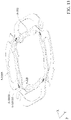
- FIG. 1 is a schematic diagram of an optical system 5 - 100 according to an embodiment of the present disclosure.
- FIG. 2 is an exploded diagram of an optical system 5 - 100 according to an embodiment of the present disclosure.
- FIG. 3 is a cross-sectional view of the optical system 5 - 100 along line 5 -A- 5 -A′ in FIG. 1 according to an embodiment of the present disclosure.
- FIG. 4 is a schematic diagram illustrating that the first optical element 5 -OE is not pushed by the deforming member 5 - 101 according to an embodiment of the present disclosure.
- FIG. 5 and FIG. 6 are schematic diagrams of the first optical element 5 -OE after being pushed by the deforming member 5 - 101 according to an embodiment of the present disclosure.
- FIG. 7 is an enlarged schematic diagram of the optical system 5 - 100 in FIG. 3 according to an embodiment of the present disclosure.
- FIG. 8 is a top view of a partial structure of the optical system 5 - 100 according to an embodiment of the present disclosure.
- FIG. 9 is a top view of a partial structure of the optical system 5 - 100 according to an embodiment of the present disclosure.
- FIG. 10 is a cross-sectional view of the optical system 5 - 100 according to another embodiment of the present disclosure.
- FIG. 11 is a schematic diagram of the movable element 5 - 103 and several elastic portions 5 - 1055 after assembly according to another embodiment of the present disclosure.
- FIG. 12 is a top view of the movable element 5 - 103 and several elastic portions 5 - 1055 after assembly according to another embodiment of the present disclosure.
- FIG. 13 is a schematic diagram of the movable element 5 - 103 and several elastic portions 5 - 1055 after assembly in another view according to another embodiment of the present disclosure.
- FIG. 14 is a schematic diagram of the movable element 5 - 103 and several elastic portions 5 - 1055 after assembly in another view according to another embodiment of the present disclosure.
- FIG. 15 is a schematic diagram of the movable element 5 - 103 and several elastic portions 5 - 1055 according to another embodiment of the present disclosure.
- FIG. 1 is a schematic diagram of an optical system 5 - 100 according to an embodiment of the present disclosure
- FIG. 2 is an exploded diagram of an optical system 5 - 100 according to an embodiment of the present disclosure
- FIG. 3 is a cross-sectional view of the optical system 5 - 100 along line 5 -A- 5 -A′ in FIG. 1 according to an embodiment of the present disclosure.
- the optical system 5 - 100 can be an optical camera system and can be configured to hold and drive a first optical element 5 -OE, and the first optical element 5 -OE may define an optical axis 5 -O.
- the optical system 5 - 100 can be installed in different electronic devices or portable electronic devices, such as a smartphone, for allowing a user to perform the image capturing function.
- the optical system 5 - 100 can be a voice coil motor (VCM) with an auto-focusing (AF) function, but it is not limited thereto.
- VCM voice coil motor
- AF auto-focusing
- the optical system 5 - 100 can also perform the functions of auto-focusing and optical image stabilization (OIS).
- the optical system 5 - 100 may include a fixed assembly 5 -FA, a deforming member 5 - 101 , a movable element 5 - 103 , and a connecting assembly 5 -CA, a movable assembly 5 -MA and a driving module 5 -DM.
- the deforming member 5 - 101 is connected between the movable element 5 - 103 and the first optical element 5 -OE, the movable element 5 - 103 is movable relative to the fixed assembly 5 -FA, and the driving module 5 -DM is configured to drive the movable element 5 - 103 to move relative to the fixed assembly 5 -FA.
- the movable assembly 5 -MA is movably connected to the movable element 5 - 103 via the connecting assembly 5 -CA, and the driving module 5 -DM drives the movable assembly 5 -MA to move relative to the fixed assembly 5 -FA, thereby driving the movable element 5 - 103 .
- the fixed assembly 5 -FA includes a casing 5 - 102 , a frame 5 - 104 , and a base 5 - 112 .
- the casing 5 - 102 is fixedly connected to the base 5 - 112
- the frame 5 - 104 can also be fixedly connected to the inner wall surface of the casing 5 - 102 .
- a main axis 5 -AX can be defined by the fixed assembly 5 -FA.
- the main axis 5 -AX is parallel to or overlaps an optical axis 5 -O of the first optical element 5 -OE.
- the movable element 5 - 103 has a movable element surface 5 - 103 S which faces the first optical element 5 -OE.
- the aforementioned casing 5 - 102 has a hollow structure, and a casing opening 5 - 1021 is formed thereon.
- a base opening 5 - 1121 is formed on the base 5 - 112 .
- the center of the casing opening 5 - 1021 corresponds to the optical axis 5 -O of the first optical element 5 -OE
- the base opening 5 - 1121 corresponds to a photosensitive element (not shown in the figure) disposed below the base 5 - 112 .
- the first optical element 5 -OE is fixedly disposed in the casing opening 5 - 1021 .
- the external light can enter the casing 5 - 102 through the first optical element 5 -OE and then is received by the aforementioned photosensitive element after passing through the base opening 5 - 1121 so as to generate a digital image signal.
- the casing 5 - 102 is disposed on the base 5 - 112 and may have an accommodating space 5 - 1023 configured to accommodate the movable element 5 - 103 , the frame 5 - 104 , and the movable assembly 5 -MA, the connecting assembly 5 -CA, and the driving module 5 -DM.
- the movable assembly 5 -MA may include four movable members (a first movable member 5 - 1081 , a second movable member 5 - 1082 , and a third movable member 5 - 1083 and a fourth movable member 5 - 1084 ), and the connecting assembly 5 -CA may include four connecting members (a first connecting member 5 - 1051 , a second connecting member 5 - 1052 , a third connecting member 5 - 1053 , and a fourth connecting member 5 - 1054 ).
- the first movable member 5 - 1081 to the fourth movable member 5 - 1084 are connected to the movable element 5 - 103 by the first connecting member 5 - 1051 to the fourth connecting member 5 - 1054 , respectively.
- the first connecting member 5 - 1051 to the fourth connecting member 5 - 1054 may each include an elastic portion 5 - 1055 and a rigid portion 5 - 1056 .
- the elastic portion 5 - 1055 is connected to the movable element 5 - 103
- the rigid portion 5 - 1056 is connected to the elastic portion 5 - 1055 by an adhesive member 5 -AD.
- multiple elastic portions 5 - 1055 form an elastic sheet and collectively surround the main axis 5 -AX, as shown in FIG. 2 .
- the optical system 5 - 100 may further include a first elastic element 5 - 106 and a second elastic element 5 - 110
- the base 5 - 112 may include four protruding columns 5 - 1123 .
- the outer portion (the outer ring portion) of the first elastic element 5 - 106 is fixedly disposed on the top surfaces of the protruding columns 5 - 1123
- the outer portion (the outer ring portion) of the second elastic element 5 - 110 is fixedly disposed on a plane 5 - 1125 of each of the protruding columns 5 - 113
- the inner portions (the inner ring portions) of the first elastic element 5 - 106 and the second elastic element 5 - 110 are respectively connected to the upper and lower sides of the movable assembly 5 -MA so that the first movable member 5 - 1081 to the fourth movable member 5 - 1084 are suspended in the accommodating space 5 - 1023 .
- the driving module 5 -DM may include four driving assemblies (a first driving assembly 5 -DA 1 , a second driving assembly 5 -DA 2 , a third driving assembly 5 -DA 3 , and a fourth driving assembly 5 -DA 4 ).
- the first driving assembly 5 -DA 1 includes a first driving coil 5 -CL 1 and a first magnetic element 5 -MG 1
- the second driving assembly 5 -DA 2 includes a second driving coil 5 -CL 2 and a second magnetic element 5 -MG 2
- the third driving assembly 5 -DA 3 includes a third driving coil 5 -CL 3 and a third magnetic element 5 -MG 3
- the fourth driving assembly 5 -DA 4 includes a fourth driving coil 5 -CL 4 and a fourth magnetic element 5 -MG 4 .
- each magnetic element has a magnetic surface.
- the first magnetic element 5 -MG 1 and the second magnetic element 5 -MG 2 respectively have a first magnetic surface 5 -MS 1 and a second magnetic surface 5 -MS 2
- the first magnetic surface 5 -MS 1 faces the first driving coil 5 -CL 1
- the second magnetic surface 5 -MS 2 faces the second driving coil 5 -CL 2
- the first magnetic surface 5 -MS 1 and the second magnetic surface 5 -MS 2 face different directions.
- the frame 5 - 104 has a plurality of grooves 5 - 1041 and a central opening 5 - 1043 .
- the frame 5 - 104 has four grooves 5 - 1041 configured to receive the four magnetic elements, but the number of the grooves 5 - 1041 and the magnetic elements is not limited to this embodiment.
- the central opening 5 - 1043 is configured to accommodate the first driving coil 5 -CL 1 to the fourth driving coil 5 -CL 4 and the first movable member 5 - 1081 to the fourth movable member 5 - 1084 .
- the first driving coil 5 -CL 1 to the fourth driving coil 5 -CL 4 may be winding coils, which are respectively disposed on the first movable member 5 - 1081 to the fourth movable member 5 - 1084 , and when the first driving coil 5 -CL 1 to the fourth driving coil 5 -CL 4 are provided with electricity, they can respectively act with the first magnetic element 5 -MG 1 to the fourth magnetic element 5 -MG 4 to generate an electromagnetic driving force to drive at least one of the first movable member 5 - 1081 to the fourth movable member 5 - 1084 to move relative to the base 5 - 112 and the frame 5 - 104 along the optical axis 5 -O (the Z-axis) so as to perform functions of auto focusing or optical image stabilization.
- the first driving coil 5 -CL 1 to the fourth driving coil 5 -CL 4 may be winding coils, which are respectively disposed on the first movable member 5 - 1081 to the fourth movable member 5 - 1084 , and when
- the driving assembly of the driving module 5 -DM can actuate individually or cooperatively.
- the first driving assembly 5 -DA 1 is configured to drive the first movable member 5 - 1081 to move relative to the fixed assembly 5 -FA
- the second driving assembly 5 -DA 2 is configured to drive the second movable member 5 - 1082 to move relative to the fixed assembly 5 -FA and the first movable member 5 - 1081 , and so on.
- the fixed assembly 5 -FA may further include at least one circuit member 5 - 170 configured to be electrically connected to the driving module 5 -DM through the first elastic element 5 - 106 or the second elastic element 5 - 110 .
- the circuit member 5 - 170 may be implemented by insert molding technology, but it is not limited thereto.
- the circuit member 5 - 170 , the first elastic element 5 - 106 , and the second elastic element 5 - 110 may constitute a circuit assembly.
- FIG. 4 is a schematic diagram illustrating that the first optical element 5 -OF is not pushed by the deforming member 5 - 101 according to an embodiment of the present disclosure
- FIG. 5 and FIG. 6 are schematic diagrams of the first optical element 5 -OE after being pushed by the deforming member 5 - 101 according to an embodiment of the present disclosure
- the first optical element 5 -OE may be a liquid lens, including a liquid lens element 5 -OE 1 and a fixed member 5 -OE 2 .
- the liquid lens element 5 -OH is disposed within of the fixed member 5 -OE 2 having a hollow structure that protects and supports the liquid lens element 5 -OE 1 .
- the deforming member 5 - 101 is disposed under the liquid lens element 5 -OE 1 and the fixed member 5 -OE 2 .
- the bottom of the fixed member 5 -OE 2 may be a thin film, so that the deforming member 5 - 101 may be used for changing the shape of the liquid lens element 5 -OE 1 .
- FIG. 4 shows that the liquid lens element 5 -OE 1 is not deformed and the deforming member 5 - 101 is in an initial position, and the liquid lens element 5 -OE 1 has an optical axis 5 -O.
- the driving module 5 -DM drives the movable assembly 5 -MA to move, for example, applying a driving current to the driving coils of the driving module 5 -DM, a magnetic force is generated between the driving coils and the corresponding magnetic elements, so that the movable assembly 5 -MA is driven to move through the magnetic force and to force the deforming member 5 - 101 though the connecting assembly 5 -CA to press the lower side of the liquid lens element 5 -OE 1 . Therefore the liquid lens element 5 -OE 1 is deformed.
- the deforming member 5 - 101 translates along the optical axis 5 -O.
- the lens curvature of the liquid lens element 5 -OE 1 is changed from the curvature of the liquid lens element 5 -OE 1 in FIG. 4 . That is, the shape of the liquid lens element 5 -OE 1 is changed. Therefore, the optical properties of the liquid lens element 5 -OE 1 can be changed, thereby achieving an optical zoom, focus or shock-proofing effect.
- the deforming member 5 - 101 obliquely moves and provides an unequal amount of pushing forces 5 -F 1 and 5 -F 3 to two different sides of the liquid lens element 5 -OE 1 , so that the optical axis 5 -O of the liquid lens element 5 -OE 1 is rotated and is deviated from the main axis 5 -AX. That is, there is an angle 5 - ⁇ 1 formed between them. Therefore, the optical properties of the liquid lens element 5 -OE 1 are changed, and the optical zoom, focusing or shock-proofing effect can be accomplished.
- FIG. 7 is an enlarged schematic diagram of the optical system 5 - 100 in FIG. 3 according to an embodiment of the present disclosure.
- the fourth connecting member 5 - 1054 has an elastic portion 5 - 1055 and a rigid portion 5 - 1056 .
- the elastic portion 5 - 1055 is not parallel to the main axis 5 -AX, for example, perpendicular to the main axis 5 -AX.
- the rigid portion 5 - 1056 is connected between the elastic portion 5 - 1055 and the fourth movable member 5 - 1084 of the movable assembly 5 -MA.
- a distance 5 -ds 1 between the movable element surface 5 - 103 S (the top surface) of the movable element 5 - 103 and the first optical element 5 -GE along the main axis 5 -AX is less than a distance 5 -ds 2 between the adhesive member 5 -AD and the first optical element 5 -OE.
- FIG. 8 is a top view of a partial structure of the optical system 5 - 100 according to an embodiment of the present disclosure.
- the elastic portion of each connecting member when viewed along the main axis 5 -AX, the elastic portion of each connecting member extends outward from the movable element 5 - 103 .
- the elastic portion 5 - 1055 of the fourth connecting member 5 - 1054 extends outward from the movable element 5 - 103 .
- the connecting assembly 5 -CA includes four connecting members, and when viewed along the main axis 5 -AX, the elastic portions of these connecting members are mirror-symmetric with respect to a first traverse axis 5 -AX 1 or a second traverse axis 5 -AX 2 .
- each connecting member may be formed by a string, extending along multiple directions which are perpendicular to the main axis 5 -AX, that is, extending along the XY plane.
- the string of the elastic portion 5 - 1055 of the fourth connecting member 5 - 1054 has a fixed width 5 -WS, and both ends of the string are connected to the movable element 5 - 103 .
- the string of the elastic portion 5 - 1055 may have two cantilever.
- the string of the elastic portion 5 - 1055 of the fourth connecting member 5 - 1054 may have a first cantilever 5 - 1057 and a second cantilever 5 - 1058 , and the first cantilever 5 - 1057 and the second cantilever 5 - 1058 are symmetrical with respect to the first traverse axis 5 -AX 1 .
- the stability of the movable assembly 5 -MA to drive the movable element 5 - 103 via the connecting assembly 5 -CA can be increased.
- the movable element 5 - 103 is driven to move only along the main axis 5 -AX and not to move along the first traverse axis 5 -AX 1 or the second traverse axis 5 -AX 2 .
- FIG. 9 is a top view of a partial structure of the optical system 5 - 100 according to an embodiment of the present disclosure.
- a surface 5 -OEBS of the first optical element 5 -OE partially overlaps at least one portion of the string.
- the surface 5 -OEBS may be the portion of projection of the liquid lens element 5 -OE 1 on the bottom surface of the fixed member 5 -OE 2 along the optical axis 5 -O in FIG. 7 .
- the surface 5 -OEBS includes a first portion 5 -POC 1 , a second portion 5 -POC 2 , and a pressed surface 5 -PRS.
- the pressed surface 5 -PRS may be an area where the deforming member 5 - 101 contacts the bottom surface of the fixed member 5 -OE 2 in FIG. 7 , and in this embodiment, the pressed surface 5 -PRS is an annular area.
- first portion 5 -POC 1 is located in the inner side of the pressured surface 5 -PRS
- second portion 5 -POC 2 is located outside the pressured surface 5 -PRS
- the string of the elastic portion 5 - 1055 of each connecting member partially overlaps at least one portion of the second portion 5 -POC 2
- the second portion 5 -POC 2 also partially overlaps the adhesive member 5 -AD, but it is not limited thereto. Ili other embodiments, the second portion 5 -POC 2 may not overlap the adhesive member 5 -AD.
- FIG. 10 is a cross-sectional view of the optical system 5 - 100 according to another embodiment of the present disclosure.
- This embodiment is similar to the previous embodiment, and their difference is that the rigid portion 5 - 1056 in this embodiment may be composed of two strings, and the two strings are mirror-symmetric with respect to the main axis 5 -AX.
- the rigid portion 5 - 1056 can be prevented from being bent along the XY plane when the movable member (such as the first movable member 5 - 1081 ) moves along the main axis 5 -AX, and the problem that the rigid portion 5 - 1056 is easily broken can also be prevented.
- FIG. 11 is a schematic diagram of the movable element 5 - 103 and several elastic portions 5 - 1055 after assembly according to another embodiment of the present disclosure
- FIG. 12 is a top view of the movable element 5 - 103 and several elastic portions 5 - 1055 after assembly according to another embodiment of the present disclosure.
- each elastic portion 5 - 1055 is composed of a single string, and the string has a non-uniform width. Based on the design of the elastic portion 5 - 1055 , the problem of damage to the elastic portion 5 - 1055 caused by stress concentration can be prevented.
- each string has a first end 5 - 10551 and a second end 5 - 10552 .
- the first end 5 - 10551 is connected to the movable element 5 - 103
- the second end 5 - 10552 is connected to the corresponding rigid portion 5 - 1056 , for example, via the adhesive member 5 -AD.
- these connecting members are rotationally symmetric with respect to the main axis 5 -AX.
- FIG. 13 is a schematic diagram of the movable element 5 - 103 and several elastic portions 5 - 1055 after assembly in another view according to another embodiment of the present disclosure.
- the string can be connected to the movable element 5 - 103 by an adhesive member 5 -AD.
- an opening 5 - 1055 H may be formed on the first end 5 - 10551 , and the adhesive member 5 -AD may be disposed within the opening 5 - 10551 - 1 , so that the elastic portion 5 - 1055 is fixed to the movable element 5 - 103 .
- the elastic portion 5 - 1055 and the movable element 5 - 103 can be made of a metal material, in addition, in other embodiments, the movable element 5 - 103 and these elastic portions 5 - 1055 (string) may be integrally formed in one piece, for example, using a stamping technique. Based on the design of one-piece, the convenience of assembly without positioning and the increase of strength can be achieved.
- FIG. 14 is a schematic diagram of the movable element 5 - 103 and several elastic portions 5 - 1055 after assembly in another view according to another embodiment of the present disclosure.
- the movable element 5 - 103 is made of plastic material, and at least one positioning portion 5 - 103 P may be formed on the movable element 5 - 103 .
- the positioning portion 5 - 103 P corresponds to the opening 5 - 105511 and is configured to position the first end 5 - 10551 of the string.
- the adhesive member 5 -AD may be further disposed in the opening 5 - 1055 H so that the first end 5 - 10551 is fixed to the movable element 5 - 103 . Based on the design of the positioning portion 5 - 103 P, the convenience of assembly and the accuracy of positioning can be increased.
- FIG. 15 is a schematic diagram of the movable element 5 - 103 and several elastic portions 5 - 1055 according to another embodiment of the present disclosure.
- the movable element 5 - 103 is made of plastic material, and these elastic portions 5 - 1055 (the strings) are made of metal material and are embedded in the movable element 5 - 103 by insert molding technology. Based on this design, the assembly convenience of the optical system 5 - 100 can be improved.
- the present disclosure provides an optical system having a first optical element 5 -OE, a deforming member 5 - 101 , a movable element 5 - 103 , a fixed assembly 5 -FA, a connecting assembly 5 -CA, a movable assembly 5 -MA, and a driving module 5 -DM.
- the movable element 5 - 103 is configured to be connected to the first optical element 5 -OE through the deforming member 5 - 101
- the movable assembly 5 -MA is connected to the movable element 5 - 103 through the connecting assembly 5 -CA.
- driving module 5 -DM is configured to drive movable assembly 5 -MA to move relative to fixed assembly 5 -FA
- the movable element 5 - 103 can be moved to drive the deforming member 5 - 101 to push the bottom of first optical element 5 -OE, thereby changing the optical properties of the liquid lens element 5 -OE 1 .
- the string of the elastic portion 5 - 1055 can be designed to include two cantilever, and based on the design of this string, the stability of the movable assembly 5 -MA to drive the movable element 5 - 103 via the connecting assembly 5 -CA can be increased.
Landscapes
- Physics & Mathematics (AREA)
- General Physics & Mathematics (AREA)
- Optics & Photonics (AREA)
- Lens Barrels (AREA)
- Adjustment Of Camera Lenses (AREA)
Abstract
Description
Claims (19)
Priority Applications (1)
| Application Number | Priority Date | Filing Date | Title |
|---|---|---|---|
| US16/750,441 US11422357B2 (en) | 2019-08-23 | 2020-01-23 | Optical system |
Applications Claiming Priority (6)
| Application Number | Priority Date | Filing Date | Title |
|---|---|---|---|
| US201962890731P | 2019-08-23 | 2019-08-23 | |
| US201962894295P | 2019-08-30 | 2019-08-30 | |
| EP19218902.5 | 2019-12-20 | ||
| EP19218902.5A EP3702822B1 (en) | 2018-12-27 | 2019-12-20 | Optical system |
| EP19218902 | 2019-12-20 | ||
| US16/750,441 US11422357B2 (en) | 2019-08-23 | 2020-01-23 | Optical system |
Publications (2)
| Publication Number | Publication Date |
|---|---|
| US20210055539A1 US20210055539A1 (en) | 2021-02-25 |
| US11422357B2 true US11422357B2 (en) | 2022-08-23 |
Family
ID=73009857
Family Applications (1)
| Application Number | Title | Priority Date | Filing Date |
|---|---|---|---|
| US16/750,441 Active 2040-03-18 US11422357B2 (en) | 2019-08-23 | 2020-01-23 | Optical system |
Country Status (2)
| Country | Link |
|---|---|
| US (1) | US11422357B2 (en) |
| CN (1) | CN211826717U (en) |
Cited By (2)
| Publication number | Priority date | Publication date | Assignee | Title |
|---|---|---|---|---|
| US20210026096A1 (en) * | 2019-07-26 | 2021-01-28 | Tdk Taiwan Corp. | Optical element driving mechanism |
| US20240176094A1 (en) * | 2022-11-28 | 2024-05-30 | Tdk Taiwan Corp. | Optical system |
Families Citing this family (3)
| Publication number | Priority date | Publication date | Assignee | Title |
|---|---|---|---|---|
| US11586006B2 (en) | 2018-12-27 | 2023-02-21 | Tdk Taiwan Corp. | Reflective element driving module |
| CN114200558B (en) * | 2021-02-04 | 2023-06-02 | 广州立景创新科技有限公司 | Zoom lens module |
| CN119567653B (en) * | 2024-11-22 | 2025-07-25 | 同济大学 | Multi-material composite super-structure unit capable of being switched in multiple states, super-structure and application of super-structure |
Citations (4)
| Publication number | Priority date | Publication date | Assignee | Title |
|---|---|---|---|---|
| US20130039640A1 (en) * | 2011-08-12 | 2013-02-14 | Sharp Kabushiki Kaisha | Camera module |
| US20160231641A1 (en) * | 2013-09-25 | 2016-08-11 | Nidec Sankyo Corporation | Optical unit with shake correction function |
| US20180059381A1 (en) * | 2016-08-25 | 2018-03-01 | Apple Inc. | Camera actuator vibration damping |
| EP3907545A1 (en) * | 2019-02-28 | 2021-11-10 | Huawei Technologies Co., Ltd. | Voice coil motor for driving liquid lens and lens assembly having voice coil motor |
-
2020
- 2020-01-23 US US16/750,441 patent/US11422357B2/en active Active
- 2020-03-24 CN CN202020382516.8U patent/CN211826717U/en active Active
Patent Citations (4)
| Publication number | Priority date | Publication date | Assignee | Title |
|---|---|---|---|---|
| US20130039640A1 (en) * | 2011-08-12 | 2013-02-14 | Sharp Kabushiki Kaisha | Camera module |
| US20160231641A1 (en) * | 2013-09-25 | 2016-08-11 | Nidec Sankyo Corporation | Optical unit with shake correction function |
| US20180059381A1 (en) * | 2016-08-25 | 2018-03-01 | Apple Inc. | Camera actuator vibration damping |
| EP3907545A1 (en) * | 2019-02-28 | 2021-11-10 | Huawei Technologies Co., Ltd. | Voice coil motor for driving liquid lens and lens assembly having voice coil motor |
Cited By (3)
| Publication number | Priority date | Publication date | Assignee | Title |
|---|---|---|---|---|
| US20210026096A1 (en) * | 2019-07-26 | 2021-01-28 | Tdk Taiwan Corp. | Optical element driving mechanism |
| US11662650B2 (en) * | 2019-07-26 | 2023-05-30 | Tdk Taiwan Corp. | Optical element driving mechanism |
| US20240176094A1 (en) * | 2022-11-28 | 2024-05-30 | Tdk Taiwan Corp. | Optical system |
Also Published As
| Publication number | Publication date |
|---|---|
| CN211826717U (en) | 2020-10-30 |
| US20210055539A1 (en) | 2021-02-25 |
Similar Documents
| Publication | Publication Date | Title |
|---|---|---|
| US11567291B2 (en) | Optical system | |
| US11719997B2 (en) | Optical element driving mechanism | |
| US11422357B2 (en) | Optical system | |
| US11181669B2 (en) | Optical system | |
| US11079565B2 (en) | Optical system | |
| US11852844B2 (en) | Optical system | |
| CN211206922U (en) | Optical assembly driving mechanism | |
| US12360331B2 (en) | Optical element driving mechanism | |
| US10809487B2 (en) | Optical system | |
| US11448895B2 (en) | Optical element driving mechanism | |
| US12360329B2 (en) | Optical system | |
| US11119294B2 (en) | Optical system | |
| JPWO2011068115A1 (en) | Lens driving device, camera module equipped with lens driving device, and mobile phone equipped with camera module | |
| US20250155669A1 (en) | Driving mechanism | |
| US11397303B2 (en) | Optical element driving mechanism | |
| US20240142746A1 (en) | Optical element driving mechanism | |
| US20200272025A1 (en) | Optical element driving mechanism and control method thereof | |
| US20230209159A1 (en) | Camera module | |
| US20200271892A1 (en) | Optical element driving mechanism | |
| US20250355318A1 (en) | Optical member driving mechanism |
Legal Events
| Date | Code | Title | Description |
|---|---|---|---|
| AS | Assignment |
Owner name: TDK TAIWAN CORP., TAIWAN Free format text: ASSIGNMENT OF ASSIGNORS INTEREST;ASSIGNORS:HU, CHAO-CHANG;CHANG, CHE-WEI;CHIANG, CHIH-WEN;AND OTHERS;SIGNING DATES FROM 20191205 TO 20191206;REEL/FRAME:051601/0048 |
|
| FEPP | Fee payment procedure |
Free format text: ENTITY STATUS SET TO UNDISCOUNTED (ORIGINAL EVENT CODE: BIG.); ENTITY STATUS OF PATENT OWNER: LARGE ENTITY |
|
| STPP | Information on status: patent application and granting procedure in general |
Free format text: APPLICATION DISPATCHED FROM PREEXAM, NOT YET DOCKETED |
|
| STPP | Information on status: patent application and granting procedure in general |
Free format text: DOCKETED NEW CASE - READY FOR EXAMINATION |
|
| STPP | Information on status: patent application and granting procedure in general |
Free format text: NON FINAL ACTION MAILED |
|
| STPP | Information on status: patent application and granting procedure in general |
Free format text: RESPONSE TO NON-FINAL OFFICE ACTION ENTERED AND FORWARDED TO EXAMINER |
|
| STPP | Information on status: patent application and granting procedure in general |
Free format text: FINAL REJECTION MAILED |
|
| STPP | Information on status: patent application and granting procedure in general |
Free format text: DOCKETED NEW CASE - READY FOR EXAMINATION |
|
| STPP | Information on status: patent application and granting procedure in general |
Free format text: NOTICE OF ALLOWANCE MAILED -- APPLICATION RECEIVED IN OFFICE OF PUBLICATIONS |
|
| STPP | Information on status: patent application and granting procedure in general |
Free format text: PUBLICATIONS -- ISSUE FEE PAYMENT VERIFIED |
|
| STCF | Information on status: patent grant |
Free format text: PATENTED CASE |
|
| MAFP | Maintenance fee payment |
Free format text: PAYMENT OF MAINTENANCE FEE, 4TH YEAR, LARGE ENTITY (ORIGINAL EVENT CODE: M1551); ENTITY STATUS OF PATENT OWNER: LARGE ENTITY Year of fee payment: 4 |