US11417907B2 - Composite polymer electrolyte (CPE) membranes for secondary solid state li-metal cells and process for the production thereof - Google Patents
Composite polymer electrolyte (CPE) membranes for secondary solid state li-metal cells and process for the production thereof Download PDFInfo
- Publication number
- US11417907B2 US11417907B2 US16/647,085 US201716647085A US11417907B2 US 11417907 B2 US11417907 B2 US 11417907B2 US 201716647085 A US201716647085 A US 201716647085A US 11417907 B2 US11417907 B2 US 11417907B2
- Authority
- US
- United States
- Prior art keywords
- active material
- curable composition
- solid electrolyte
- polymer
- material layer
- Prior art date
- Legal status (The legal status is an assumption and is not a legal conclusion. Google has not performed a legal analysis and makes no representation as to the accuracy of the status listed.)
- Active, expires
Links
Images


Classifications
-
- H—ELECTRICITY
- H01—ELECTRIC ELEMENTS
- H01M—PROCESSES OR MEANS, e.g. BATTERIES, FOR THE DIRECT CONVERSION OF CHEMICAL ENERGY INTO ELECTRICAL ENERGY
- H01M10/00—Secondary cells; Manufacture thereof
- H01M10/05—Accumulators with non-aqueous electrolyte
- H01M10/052—Li-accumulators
-
- H—ELECTRICITY
- H01—ELECTRIC ELEMENTS
- H01M—PROCESSES OR MEANS, e.g. BATTERIES, FOR THE DIRECT CONVERSION OF CHEMICAL ENERGY INTO ELECTRICAL ENERGY
- H01M10/00—Secondary cells; Manufacture thereof
- H01M10/05—Accumulators with non-aqueous electrolyte
- H01M10/056—Accumulators with non-aqueous electrolyte characterised by the materials used as electrolytes, e.g. mixed inorganic/organic electrolytes
- H01M10/0561—Accumulators with non-aqueous electrolyte characterised by the materials used as electrolytes, e.g. mixed inorganic/organic electrolytes the electrolyte being constituted of inorganic materials only
- H01M10/0562—Solid materials
-
- H—ELECTRICITY
- H01—ELECTRIC ELEMENTS
- H01M—PROCESSES OR MEANS, e.g. BATTERIES, FOR THE DIRECT CONVERSION OF CHEMICAL ENERGY INTO ELECTRICAL ENERGY
- H01M10/00—Secondary cells; Manufacture thereof
- H01M10/05—Accumulators with non-aqueous electrolyte
- H01M10/056—Accumulators with non-aqueous electrolyte characterised by the materials used as electrolytes, e.g. mixed inorganic/organic electrolytes
- H01M10/0564—Accumulators with non-aqueous electrolyte characterised by the materials used as electrolytes, e.g. mixed inorganic/organic electrolytes the electrolyte being constituted of organic materials only
- H01M10/0565—Polymeric materials, e.g. gel-type or solid-type
-
- H—ELECTRICITY
- H01—ELECTRIC ELEMENTS
- H01M—PROCESSES OR MEANS, e.g. BATTERIES, FOR THE DIRECT CONVERSION OF CHEMICAL ENERGY INTO ELECTRICAL ENERGY
- H01M10/00—Secondary cells; Manufacture thereof
- H01M10/05—Accumulators with non-aqueous electrolyte
- H01M10/058—Construction or manufacture
- H01M10/0585—Construction or manufacture of accumulators having only flat construction elements, i.e. flat positive electrodes, flat negative electrodes and flat separators
-
- H—ELECTRICITY
- H01—ELECTRIC ELEMENTS
- H01M—PROCESSES OR MEANS, e.g. BATTERIES, FOR THE DIRECT CONVERSION OF CHEMICAL ENERGY INTO ELECTRICAL ENERGY
- H01M2300/00—Electrolytes
- H01M2300/0017—Non-aqueous electrolytes
- H01M2300/0065—Solid electrolytes
- H01M2300/0068—Solid electrolytes inorganic
- H01M2300/0071—Oxides
- H01M2300/0074—Ion conductive at high temperature
- H01M2300/0077—Ion conductive at high temperature based on zirconium oxide
-
- H—ELECTRICITY
- H01—ELECTRIC ELEMENTS
- H01M—PROCESSES OR MEANS, e.g. BATTERIES, FOR THE DIRECT CONVERSION OF CHEMICAL ENERGY INTO ELECTRICAL ENERGY
- H01M2300/00—Electrolytes
- H01M2300/0017—Non-aqueous electrolytes
- H01M2300/0065—Solid electrolytes
- H01M2300/0082—Organic polymers
-
- H—ELECTRICITY
- H01—ELECTRIC ELEMENTS
- H01M—PROCESSES OR MEANS, e.g. BATTERIES, FOR THE DIRECT CONVERSION OF CHEMICAL ENERGY INTO ELECTRICAL ENERGY
- H01M2300/00—Electrolytes
- H01M2300/0088—Composites
- H01M2300/0091—Composites in the form of mixtures
-
- Y—GENERAL TAGGING OF NEW TECHNOLOGICAL DEVELOPMENTS; GENERAL TAGGING OF CROSS-SECTIONAL TECHNOLOGIES SPANNING OVER SEVERAL SECTIONS OF THE IPC; TECHNICAL SUBJECTS COVERED BY FORMER USPC CROSS-REFERENCE ART COLLECTIONS [XRACs] AND DIGESTS
- Y02—TECHNOLOGIES OR APPLICATIONS FOR MITIGATION OR ADAPTATION AGAINST CLIMATE CHANGE
- Y02E—REDUCTION OF GREENHOUSE GAS [GHG] EMISSIONS, RELATED TO ENERGY GENERATION, TRANSMISSION OR DISTRIBUTION
- Y02E60/00—Enabling technologies; Technologies with a potential or indirect contribution to GHG emissions mitigation
- Y02E60/10—Energy storage using batteries
Definitions
- the present invention relates to curable compositions for preparing composite polymer electrolyte (CPE) membranes, processes for preparing such compositions, films based on such curable compositions, and such compositions and films as cured by ultraviolet light (UV), notably to produce membranes for use in solid-state lithium batteries.
- CPE composite polymer electrolyte
- UV ultraviolet light
- Highly crosslinked polymer structures can be obtained in the composite polymer membranes, and they may enable solid-state lithium batteries to be obtained working at 20° C. at high current rate.
- PA1 discloses a process for the production of a polymer electrolyte membrane, which comprises the successive steps of: preparing a mixed solution of a Room Temperature Ionic Liquid (RTIL), at least one alkaline metal salt and a photosensitive hydrogen abstracting component at a temperature in the range of 20 to 70° C.; adding to the solution a polymeric material at a temperature in the range of 20-70° C.; blending the solution added with the polymeric material at a temperature in the range of 70-140° C. to get a uniform mixture; pressing the mixture between two sheets at a temperature in the range of 60-150° C.
- RTIL Room Temperature Ionic Liquid
- PA2 discloses a composite electrolyte comprising a lithium-ion-conducting glass ceramic, a polymer, an ionic liquid and a lithium salt.
- the lithium-ion-conducting glass ceramic may be a lithium compound with garnet structure.
- RTILs Room Temperature Ionic Liquids
- the batteries of PA3 appear to show relatively low capacity.
- PA4 (WO 2009/070600) discloses electrolyte separators including two phases, a first phase comprising poly(alkylene oxide) and an alkali-metal salt and a second phase comprising ionically conductive particles.
- Lithium aluminium titanium phosphate (LATP) is most preferred as ionically conductive particles.
- PA5 Patent Application Laidi et al. discloses polymer electrolytes obtained by UV-induced (co)polymerization, based on compositions containing polyethyleneoxide (PEO) plasticized by tetraglyme at various lithium salt concentrations. In this PA5, there is no step of distillation of the plasticizer.
- PEO polyethyleneoxide
- the present invention seeks to provide a composite polymer electrolyte (CPE) able to provide one or more of the following advantages: long-term cycling (e.g. more than 300 cycles) of an all solid state Li-metal cell even at ambient temperatures; high capacity retention (e.g. at least 50% after 100 cycles) at high rate current (1 full charge in 1 h) even at ambient temperatures.
- CPE composite polymer electrolyte
- composite polymer electrolyte (CPE) membranes may show one or more of the following additional advantages: (1) since a CPE membrane of the present invention can be prepared as a completely dry membrane, it is possible to stack cells into bipolar or monopolar configurations; (2) a CPE membrane of the present invention can work at room temperature so there is no need of a constant heating like in Bolloré cars (>50° C.); (3) a CPE membrane of the present invention may be safer because of the presence of less or no dendrite, and (4) safer because it is non-flammable.
- the present invention also seeks to provide a process for preparing a composite polymer electrolyte (CPE) with no need to apply high temperatures (100° C. or higher).
- Other advantages that the processes and/or products of the invention may provide include no leakage of flammable solvents with high vapour pressure, and/or shape/thickness retention at a large range of temperatures and/or under mechanical stress.
- the present invention relates, in one aspect thereof, to a curable composition for preparing a composite polymer electrolyte, the curable composition containing:
- M II is at least one cation from the alkaline earth metal group or from the same group of the Periodic Table as Zn 2+ ,
- M III is at least one cation chosen among La 3+ , Al 3+ , Cr 3+ , Ga 3+ , Bi 3+ , Y 3+ , In 3+ and/or Fe 3+ ,
- M IV is at least one cation chosen among Zr 4+ , Ti 4+ , Hf 4+ , Sn 4+ and/or Si 4+
- M V is at least one cation chosen among Nb 5+ , Ta 5+ , V 5+ and/or P 5+ ;
- 0 ⁇ y ⁇ 2 preferably 0 ⁇ y ⁇ 1;
- the present invention further relates, in a different aspect thereof, to a process of preparing a composition according to the invention comprising the mixing of components (A) to (E), with optional grinding, at a temperature not exceeding 100° C.
- the present invention further relates, in a different aspect thereof, to a film having a composition as defined above for the curable composition of the invention.
- a film having a composition as defined above for the curable composition of the invention may appropriately have a thickness of at least 0.5 ⁇ m and at most 500 ⁇ m, preferably at least 1.0 ⁇ m and at most 200 ⁇ m.
- the present invention further relates, in a different aspect thereof, to a cured composition obtained by exposure of the curable composition of the invention to UV light.
- the present invention further relates, in a different aspect thereof, to a cured film obtained by exposure to UV light of the film prepared using the curable composition of the invention.
- the present invention further relates, in a different aspect thereof, to a solid-state lithium battery comprising the following elements:
- FIG. 1 shows an illustrative and non-limiting schematic representation of different parts of an exemplary composite polymer electrolyte (CPE) disclosed in the present invention.
- element 1 is Li-ion conducting solid electrolyte (A), the numeral 2 designating the group of species consisting of: polymer (B), lithium salt (C), active plasticizer (D), photoinitiator (E).
- FIG. 2 based on experimental results shown in the present invention, enables visualisation of advantages provided by the invention such as higher capacity retention for a Li metal cell using LiFePO 4 as positive active material and lithium as negative electrode and CPE prepared using the process as described in FIG. 3 a following option 2b of this process and using 40 wt % of garnet phase.
- the cell was cycled at a 1C rate (1 charge in 1 hour) at 20° C.
- FIG. 3 a shows schematically an illustrative and non-limiting process used to prepare a composite polymer electrolyte as disclosed in the present invention and illustrated in worked Examples 1 to 3.
- FIG. 3 b represents schematically a process used to make a polymer electrolyte as disclosed in PA5 (Porcarelli et al.) and in Comparative Example 1 of the present disclosure. It is to be note however that for present Comparative Example 1 the plasticizer is well dried, which is not the case in PA5.
- FIG. 4 shows an experimental comparison of capacity obtained after a 1 st cycle for a Li metal cell using LiFePO 4 as positive active material, lithium as negative electrode and a composite polymer electrolyte (CPE) prepared using a process as described in FIG. 3 a following option 2b of this process and using 40 wt % of garnet phase and solid polymer electrolyte (SPE) prepared using process as described in FIG. 3 b.
- CPE composite polymer electrolyte
- FIG. 5 a shows an experimental comparison of performances for a Li metal cell using LiFePO 4 as positive active material and lithium as negative electrode and CPE prepared using process as described in FIG. 3 a following option 2b of this process and using 40 wt % of garnet phase.
- the cell was cycled at a 1C rate (1 charge in 1 hour) at 20° C.
- FIG. 5 b shows an experimental comparison of performances for a Li metal cell using LiFePO 4 as positive active material and lithium as negative electrode and CPE prepared using process as described in FIG. 3 a following option 2b of this process and using 40 wt % of garnet phase.
- the cell was cycled at a 1C rate (1 charge in 1 hour) at 40° C.
- FIG. 6 illustrates in a non-limiting way a study of capacity retention after 100 cycles at a 1C current rate at ambient temperature with respect to the weight ratio of cubic garnet phase.
- FIG. 7 a shows schematically a lithium metal cell using CPE disclosed in the present invention during discharge stage.
- FIG. 7 b shows schematically a lithium metal cell using CPE disclosed in the present invention during charge stage.
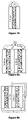
- FIG. 8 a shows schematically a lithium metal bipolar cell using CPE disclosed in the present invention during discharge stage.
- FIG. 8 b shows schematically a lithium metal monopolar cell using CPE disclosed in the present invention during discharge stage.
- the Li-ion conducting solid electrolyte (A) is notably a material with garnet phase and notably a cubic garnet structure.
- the Li-ion conducting solid electrolyte (A) used in the curable composition of the present invention preferably has an ionic conductivity of >0.5 mS cm ⁇ 1 at 25° C., and/or is present with an average particle size from 1 ⁇ m to 50 ⁇ m.
- the maximum particle size of sample may be fixed at, for example, 50 ⁇ m or 40 ⁇ m. In one embodiment of the present invention, the preferred maximum particle size of Li-ion conducting solid electrolyte (A) used is 32 ⁇ m.
- the preferred amount of Li-ion conducting solid electrolyte (A), with respect to 100% by weight of the overall curable composition is at least 5 wt % and at most 80 wt %, more preferably at least 20 wt % and at most 60 wt %, still more preferably at least 30 wt % and at most 50 wt %.
- a particularly preferred Li-ion conducting solid electrolyte (A) to be used in the present invention is lithium-lanthanum-zirconate (LLZO).
- LLZO may show the chemical formula Li 7 La 3 Zr 2 O 12 .
- LLZO is advantageously used with the ionic conductivity, average particle size and weight percentage amounts indicated above for component (A) of the curable composition of the present invention.
- the polymer (B) is advantageously a good dielectric material with an electronic conductivity, if the polymer (B) is taken in isolation, of less than 10 ⁇ 10 S ⁇ cm ⁇ 1 .
- the polymer (B) shows repeating units containing heteroatoms such as nitrogen, oxygen or sulphur.
- polymer (B) shows functional groups available for UV/thermally initiated radical polymerisation/cross-linking (e.g. double bonds, acidic protons).
- a particularly preferred type of polymer (B) for use in the present invention is constituted by the group of polyethers/poly(alkylene oxides), for example poly(ethylene oxide) (PEO) and poly(propylene oxide) (PPO).
- PEO poly(ethylene oxide)
- PPO poly(propylene oxide)
- polymer (B) for use in the present invention include: polyacrylonitrile (PAN); polycarbonates (PC); polyesters and polylactones, for example polycaprolactone (PCL); poly(meth)acrylate esters, such as poly(methyl methacrylate) (PMMA).
- PAN polyacrylonitrile
- PC polycarbonates
- PCL polyesters and polylactones, for example polycaprolactone (PCL)
- PCL polycaprolactone
- PMMA poly(meth)acrylate esters, such as poly(methyl methacrylate)
- polymer (B) in the present invention are block copolymers of the above-mentioned polymer types e.g. PEO-PMMA or PEO-PMMA-PEO or PEO-PPO-PEO, PEO-PCL, etc.
- a preferred minimum average molecular weight is at least 500, more preferably 10 3 , still more preferably at least 10 4 .
- molecular weights of up to 10 7 can be used, although in general 10 6 is a suitable upper limit.
- Appropriate molecular weight ranges, for example for preferred poly(alkylene oxides) polymers such as poly(ethylene oxide) (PEO), may be in the range of 100 000 to 500 000, for example 200 000.
- the preferred amount of polymer (B), with respect to 100% by weight of the overall curable composition is at least 7 wt % and at most 40 wt %, more preferably at least 12 wt % and at most 35 wt %.
- the lithium salt (C) is one or preferably one or more selected from the group consisting of: LiPF 6 , LiBF 4 , LiClO 4 , LiFSI, LiTFSI, LiBOB LiAsF 6 , LiFAP, LiTriflate, LiDMSI, LiHPSI, LiBETI, LiDFOB, LiBFMB, LiBison, LiDCTA, LiTDI, LiPDI.
- LiPF 6 LiBF 4 , LiClO 4 , LiFSI, LiTFSI, LiBOB LiAsF 6 , LiFAP, LiTriflate, LiDMSI, LiHPSI, LiBETI, LiDFOB, LiBFMB, LiBison, LiDCTA, LiTDI, LiPDI.
- the preferred amount of lithium salt (C), with respect to 100% by weight of the overall curable composition is at least 1 wt % and at most 30 wt %, more preferably at least 5 wt % and at most 15 wt %.
- the active plasticizer (D) is considered to be able to take part in the polymerization process that can decrease the viscosity of the final product.
- the active plasticizer has a boiling point of more than 120° C.
- active plasticizer are oligomeric polyethers with alkoxy, such as methoxy, end-capping groups e.g. glymes.
- Preferred active plasticizers (D) thus include: dimethoxytetraethylene glycol (TEGDME), diethylene glycol dimethyl ether (diglyme), triethylene glycol dimethyl ether (triglyme), poly(ethylene glycol) dimethyl ether (MW from 90 to 225 g ⁇ mol ⁇ 1 ).
- active plasticizers (D) include low molecular weight oligomeric PCL, PC, polylactones, dialkyl sulfoxides, etc. It is envisaged that the active plasticizer (D) is able to donate hydrogen in cross-linking reactions.
- suitable molecular weights for the active plasticizers (D) are less than 500, preferably less than 400, more preferably less than 300, still more preferably less than 250 and most preferably less than or equal to 225.
- the active plasticizer (D) has a water content below 10 ppm, and preferably below 5 ppm. This is for example achieved via a distillation process and/or via a drying step on molecular sieves and/or via a combination of both a distillation process and a drying step on molecular sieves to ensure the purity of the active plasticizer (D).
- the inventors consider that when there is still some water in the polymer membrane, the ionic conductivity may be higher. However, in order to avoid the formation of an interface layer on the surface of the Li-ion conducting solid electrolyte, it is preferable to have as much as possible dried materials.
- the preferred amount of active plasticizer (D), with respect to 100% by weight of the overall curable composition is at least 1 wt % and at most 50 wt %, more preferably at least 12 wt % and at most 35 wt %.
- the photoinitiator (E) is considered to act as a light-induced hydrogen abstraction mediator able to give a cross-linking effect with the plasticizer and polymer chain.
- Preferred examples of photoinitiator are those having an aryl-CO— group, such as those having a benzophenone structure, for example 4-methylbenzophenone, benzophenone, chlorobenzophenone, or Darocur ⁇ (from BASF) and their blends.
- Generally useful photoinitiators are able to abstract hydrogen atoms (H).
- Fluorenones, xanthones, benzils, anthraquinones, terephthalophenones are other examples of possible photoinitiators in the present invention showing an aryl-CO— group, the aryl system being not necessarily an unsubstituted aryl (phenyl) ring, but potentially having substitution.
- Examples of carbonyl group-containing photoinitiators not having an aryl group adjacent to the CO group include alpha-ketocoumarins and terephthalophenones.
- Preferred photoinitiators (E) in the present invention are notably able to absorb light in the range 200-400 nm and belong to the class of free-radical photoinitiators, notably Type II photoinitiators.
- the preferred amount of photoinitiator (E), with respect to 100% by weight of the overall curable composition is at least 1 wt % and at most 12 wt %, more preferably at least 3 wt % and at most 7.5 wt %.
- Such optional further additives may for example include one or more of:
- G ceramic filler (SiO 2 , Al 2 O 3 , MgO, ZrO 2 , CaO, BaO, La 2 O 3 , Bi 2 O 3 , Ga 2 O 3 , Cr 2 O 3 , Ta 2 O 5 , V 2 O 5 , P 2 O 5 , Mg 3 Al 2 Si 3 O 12 , Fe 3 Al 2 Si 3 O 12 , Ca 3 Fe 2 Si 3 O 12 , Ca 3 Al 2 Si 3 O 12 , Ca 3 Cr 2 Si 3 O 12 ), or sand grain, with a particle size from 10 nm to 100 ⁇ m;
- binding agents such as: polyvinylidene fluoride (PVdF), styrene-butadiene rubber (SBR), carboxymethyl cellulose (CMC), polytetrafluoroethylene (PTFE);
- PVdF polyvinylidene fluoride
- SBR styrene-butadiene rubber
- CMC carboxymethyl cellulose
- PTFE polytetrafluoroethylene
- some surfactants can be added along with some processing aids.
- Possible examples of classes of appropriate surfactant include non-ionic surfactants such as alkyl polyglycosides or poloxamers.
- RTIL Room Temperature Ionic Liquid
- Typical RTILs are compounds having at least one organic cation associated with at least one organic or inorganic anion.
- the organic cation is commonly selected in the group consisting of imidazolium, ammonium, pyridinium, pyrrolidinium, piperidinium, phosphonium and sulfonium and is associated with an organic or inorganic anion.
- the preferred amount of Room Temperature Ionic Liquid (RTIL), with respect to 100% by weight of the overall curable composition of the present invention, is less than 10 wt %, more preferably less than 5 wt %, still more preferably less than 2 wt %, further more preferably less than 1 wt %, and in a preferable embodiment the curable composition of the present invention is substantially or completely free of Room Temperature Ionic Liquid (RTIL).
- the Li-ion conducting solid electrolyte (A) on the one hand, and the other components (B) to (E) on the other hand (and optional further components (F), (G), (H), (I) etc.) may advantageously be mixed in a non-obvious dried way in order to:
- Organic solvents that may generally be used in conventional polymer electrolyte and electrode manufacture include: alcohols, ethers, ketones, carbonates, hydrocarbons, halogenated (e.g. chlorinated or fluorinated) hydrocarbons, sulfoxides, acetonitrile, (N-alkylated) amides, etc. Avoiding the use of organic solvents may show advantages such as reduced cost, increased safety, and reduced environmental burden. In preferred process embodiments of the invention, no organic solvent is added to the mixture of components (A) through to (E).
- the active plasticizer (D) in particular may be a species, such a glyme, that is under more general circumstances in chemical technologies considered to have “organic solvent” properties.
- a certain quantity of “organic solvent” may be considered to be present in the mixture of components (A) through to (E), but in preferred process embodiments according to the present invention, no further organic solvent is added beyond that which may be considered to be constituted by one or more of the components (A) through to (E) by themselves, and in particular the active plasticizer (D).
- Step 1 In an dry box under inert atmosphere (for example, Ar filled with O 2 ⁇ 5 ppm, H 2 O ⁇ 1 ppm), for example using a beaker, lithium salt (C) and photoinitiator (E) are stirred with the active plasticizer (D).
- inert atmosphere for example, Ar filled with O 2 ⁇ 5 ppm, H 2 O ⁇ 1 ppm
- Step 2 Li-ion conducting solid electrolyte (A), here illustrated as garnet phase A) is added under stirring following one of the following different options:
- Component (A) (here, garnet phase (A)) is added as received;
- Option 2b Only component (A) (here, garnet phase (A)) below a certain particle size is added, for example the fraction sieved with 32 ⁇ m mesh;
- Option 2c Only the coarse fraction of garnet phase component (A) (here, garnet phase (A)) is added, for example the fraction sieved with 32 ⁇ m mesh; It is considered that it is possible (option 2a) to use the ceramic material as received, notably if the membrane thickness is allowed to be >200 ⁇ m, in particular for garnet contents up to 50% by weight. However, in some instances, when using option 2a, with several different particle sizes, the homogeneity of the preparation of polymer/ceramic phase is not optimal at the end of the process. For option 2c, using large particles, the volumetric proportion of ceramic compared to the polymer may be too high and may create some mechanical problems for the membrane after the UV curing. In a preferred process embodiment, option 2b is therefore used, i.e. a maximum particle size is fixed, by sieving as necessary.
- Step 3 Polymer chain (B) is added under stirring.
- Step 4 and step 5 The mixture is e.g. hand-ground in a mortar and heated, for example at 70-80° C. on a hot plate for 1 h. These steps may appropriately be repeated three times. At the end of these steps a homogeneous mixture is obtained.
- Step 6 The mixture is placed between two sheets e.g. of Mylar (multiple layers of adhesive tape are used as spacers, thickness can be tuned between 80 and 250 ⁇ m, more preferably fixed at about 180 ⁇ m). Optionally this stack is sealed inside a polypropylene document bag.
- two sheets e.g. of Mylar (multiple layers of adhesive tape are used as spacers, thickness can be tuned between 80 and 250 ⁇ m, more preferably fixed at about 180 ⁇ m).
- this stack is sealed inside a polypropylene document bag.
- Step 7 The sample is hot-pressed e.g. for 15 min with a pressure of e.g. 20 bar at temperature between 25° C. and 90° C. using a heat press machine. At the end of this step, a CPE with controlled thickness is obtained.
- Step 8 The membrane is UV-cured, for example using UV light box with a power between 20 and 200 mW/cm 2 and for a duration of 1 min to 30 min. As a very specific illustrative example, one may use a UV light box for 6 minutes at 40 mW/cm 2 . At the end of this step a cross-linked CPE is obtained.
- Step 9 The CPE is carefully peeled (e.g. from the two Mylar foils), here in the glove box, in this illustrative embodiment.
- the CPE thus obtained is ready to be used as separating electrolyte in a Li metal cell (see FIG. 7 ).
- an all-solid-state secondary lithium battery comprising the following elements:
- the negative electrode is Li metal.
- the Li metal may be in the form of Li foil or Li particles.
- the thickness of a solid electrolyte layer although this may change with the kind of solid electrolyte materials, and the overall composition of an all-solid battery, generally it is preferable that this thickness is within the range of 0.5 ⁇ m to 1000 ⁇ m, more preferably within the range of 30 ⁇ m to 200 ⁇ m, still more preferably 50 ⁇ m to 200 ⁇ m.
- the solid electrolyte layer will appropriately be thicker than the maximum particle size in the (A) Li-ion conducting solid electrolyte of the invention.
- the positive active material (cathode active material) to be used in the positive electrode (cathode) active material layer this is not especially limited if the average operating potential becomes more than 3 V (vs. Li + /Li).
- the average operating potential of positive active material this is appropriately more than 3 V (vs. Li + /Li), and it is preferable that it is within the limits of 2.0 V to 6.0 V, still more preferably within the limits of 3 V to 5 V.
- the average operating potential can be evaluated using cyclic voltammetry, for example.
- the material is an oxide positive active material, which can have a high energy density.
- a compound which has the spinel type structure denoted by general formula LiM 2 O 4 (M is at least one kind of transition metal element), as an example of positive active material, can be mentioned as an example.
- M of the above-mentioned general formula LiM 2 O 4 especially if it is a transition metal element, it will not be limited, but it is preferable that it is at least one kind chosen from the group which consists of Ni, Mn, Cr, Co, V, and Ti, for example, and it is more preferable that it is at least one kind chosen from the group which consists of Ni, Mn, and Cr especially.
- LiCr 0.05 Ni 0.50 Mn 1.45 O 4 LiCrMnO 4 , LiNi 0.5 Mn 1.5 O 4 , etc.
- the compound which has the olivine type structure denoted by general formula LiMPO 4 (M is at least one kind of transition metal element) as other examples of positive active material can be mentioned.
- M in the above-mentioned general formula will not be limited especially if it is a transition metal element, but it is preferable that it is at least one kind chosen from Fe, Mn, Co, Ni, and the group of the Periodic Table that consists of V, Nb, Ta, for example, and it is more preferable that it is at least one kind chosen from the group which consists of Fe, Mn, Co, and Ni especially.
- LiFePO 4 , LiMnPO 4 , LiCoPO 4 , LiNiPO 4 , etc. can be mentioned.
- the compound which has the layer structure denoted by general formula LiMO 2 (M is at least 1 type of a transition metal element) as other examples of positive active material can be mentioned.
- LiCoO 2 , LiNi 0.5 Mn 0.5 O 2 and LiNi 0.33 Co 0.33 Mn 0.33 O 2 etc. can be mentioned.
- a Li 2 MnO 3 —LiN 1/3 Co 1/3 Mn 1/3 O 2 solid solution a Li 2 MnO 3 —LiNi 0.5 Mn 1/5 O 2 solid solution, a Li 2 MnO 3 —LiFeO 2 solid solution, etc. can be mentioned.
- a particle shape such as the shape of a true ball and the shape of an elliptical ball, etc. can be mentioned, as an example.
- the mean particle diameter when the positive active material has a particle shape, it is preferable that it is within the size range of 0.1 ⁇ m to 50 ⁇ m, for example, sometimes even in the nanometer range.
- the content of the positive active material in a positive active material layer it is preferable that it is in the range of 10% by weight to 99% by weight, for example, more preferably from 20% by weight to 90% by weight.
- a positive active material layer may contain an electrically conductive agent from a viewpoint of improving the conductivity of a positive active material layer.
- electrically conductive material acetylene black, Ketjenblack, a carbon fiber, carbon nanotube (CNT), carbon nanofibers (CNF) etc. can be mentioned, for example.
- a positive active material may also contain a binding agent.
- fluorine-based binding materials such as polyvinylidene fluoride (PVDF) and polytetrafluoroethylene (PTFE), etc. can be mentioned, for example.
- PVDF polyvinylidene fluoride
- PTFE polytetrafluoroethylene
- the thickness of a positive active material layer may change according to the kind of all-solid-state battery made, it is generally preferable that it is within the range of 0.1 ⁇ m to 500 ⁇ m.
- the positive electrode is preferably dried before assembly. This drying process may also appropriately be applied for negative electrode too.
- this layer at least contains one or more negative electrode active material(s), and may additionally contain at least one or more of solid electrolyte materials and electrically conductive agents if needed.
- the negative electrode active material is not limited provided that occlusion and discharge of the Li ion, which is a conduction ion, are possible.
- a negative electrode active material a carbon active material, a metal active material, etc. can be mentioned, for example.
- a carbon active material black lead, mesocarbon microbeads (MCMB), highly ordered/oriented pyrolytic graphite (HOPG), hard carbon, soft carbon, etc. can be mentioned as examples.
- a metal active material an alloy, such as Li alloy and Sn—Co—C, In, Al, Si, Sn, etc. can be mentioned as examples.
- Oxide stock materials such as Li 4 Ti 5 O 12 or TiO 2 , can be mentioned as examples of other negative electrode active materials.
- the most preferred negative electrode active material is lithium metal (Li metal).
- Li metal may appropriately be used alone in the negative electrode notably because Li metal is at the same time an active material, electrical conductor and ionic conductor, such that there is no need to add other materials to obtain an electrode when using Li metal.
- the use of Li metal represents a huge improvement for volumetric and specific (gravimetric) energy density (Wh ⁇ l ⁇ 1 and Wh ⁇ kg ⁇ 1 ).
- solid electrolyte materials used for the negative electrode active material layer may be the same as that for the solid electrolyte layer and positive active material layer mentioned above.
- the thickness of the negative electrode active material layer will generally be appropriately within the range of 0.1 ⁇ m to 500 ⁇ m.
- An all-solid-state battery of the present disclosure has at least the positive active material layer, solid electrolyte layer, and negative electrode active material layer which were mentioned above. It further usually has a positive current collector which collects a positive active material layer, and a negative pole collector which performs current collection of a negative electrode active material layer.
- a positive current collector for example, SUS (stainless steel), aluminum, nickel, iron, titanium, carbon, etc. can be mentioned, and SUS is especially preferable.
- SUS silver, aluminum, nickel, iron, titanium, carbon, etc.
- SUS is especially preferable.
- SUS silver
- copper, nickel, carbon, etc. can be mentioned, for example, and SUS is especially preferable. Concerning the thickness, form, etc.
- the cell case used for a common all-solid-state battery can be used, for example, the cell case made from SUS, etc. can be mentioned.
- the all-solid-state battery of the present disclosure can be considered as a chargeable and dischargeable all-solid-state battery in a room temperature environment. Although it may be a primary battery and may be a rechargeable battery, it is especially preferable that it is a rechargeable battery. Concerning the form of the all-solid-state battery, a coin type, a laminated type, cylindrical, a square shape, etc. can be mentioned, as examples.
- the manufacturing method of the all-solid-state battery this is not particularly limited, and common manufacturing methods of all-solid-state batteries can be used.
- a positive active material layer can be formed on a substrate, and a method of forming a solid electrolyte layer and a negative electrode active material layer in order, and laminating them thereafter etc., may be used, but other process variants can be envisaged.
- the (curable, as-yet uncured) curable composition (for preparing a composite polymer electrolyte) of the invention can be directly polymerized (UV cured) in-situ on top of an electrode material film.
- the solid state lithium battery of the present invention may be assembled in a monopolar or bipolar configurations.
- a monopolar configuration cf. FIG. 8 a
- a monopolar configuration is a way a have a stack of two or more (n) same simple cells (cf. FIGS. 7 a and 7 b ).
- a same current collector metal foil
- the stack cell, or monopolar configuration cell has the same voltage as one cell but with n times the capacity of 1 simple cell. (this may be compared with a parallel configuration in electric circuit).
- a bipolar configuration (cf. FIG. 8 b ) is a way to have a stack of two or more (n) same simple cells (cf.
- FIGS. 7 a and 7 b In this configuration a same current collector (metal foil) is shared between positive electrode of cell number n and negative electrode of cell number (n ⁇ 1). In this way the stack cell, or bipolar configuration cell, has the same capacity as one cell but with n times the voltage of one simple cell.
- This example shows the preparation of a solid composite polymer electrolyte (CPE) following option 2b of process described in FIG. 3 a using 20 wt % of garnet phase.
- CPE solid composite polymer electrolyte
- the sample was placed between two Mylar sheets (multiple layers of adhesive tape were used as spacers, resulting in a thickness of ⁇ 180 ⁇ m) and sealed inside a polypropylene bag.
- the sample was hot-pressed at 70° C. for 15 minutes with pressure of 20 bar using heat press machine placed in a dry room (10 m 2 , average R.H. ⁇ 2% at 20° C.).
- the CPE was UV-cured for 6 minutes at 40 mW ⁇ cm ⁇ 2 .
- the CPE was carefully peeled from the two Mylar foils in glove box to be used in a lab-scale lithium cell.
- the cathodes were prepared by standard procedure from a slurry based on N-methyl pyrrolidone containing LiFePO 4 (from Clariant-LP2: Life Power® P2, particle size 100-300 nm, prepared by a wet process, not carbon-coated) as active material, carbon black and PVdF in 70:20:10 weight ratio, respectively.
- the slurry was deposited onto an Al foil and later dried overnight (120° C.).
- the cells were tested with an ARBIN BT2000 battery tester with galvanostatic test between 2.7 V vs. Li + /Li and 4 V vs. Li + /Li. Capacity obtained at ambient temperature for 1C current rate of this cell after 100 cycles is shown in Table 1 below.
- This example shows the preparation of a solid composite polymer electrolyte (CPE) following option 2b of process of process described in FIG. 3 a using 40 wt % of garnet phase.
- CPE solid composite polymer electrolyte
- the sample was placed between two Mylar sheets (multiple layers of adhesive tape were used as spacers, resulting in a thickness of ⁇ 180 ⁇ m) and sealed inside a polypropylene bag.
- the sample was hot-pressed at 70° C. for 15 min with pressure of 20 bar using heat press machine placed in a dry room (10 m 2 , average R.H. ⁇ 2% at 20° C.).
- the CPE was UV-cured for 6 minutes at 40 mW ⁇ cm ⁇ 2 .
- the CPE was carefully peeled from the two Mylar foils in glove box to be used in battery cell.
- Example 2 The same preparation as the one reported for Example 1 was applied for Example 2.
- Example 2 The same manufacture method for a cell as the one reported for Example 1 was applied for Example 2.
- the cells were tested with an ARBIN BT2000 battery tester with galvanostatic test between 2.7 V vs. Li + /Li and 4 V vs. Li + /Li.
- Capacities obtained after the 1 st cycle at room temperature and 40° C. for different current rates are presented on FIG. 4 and compared with prior art (Comparative Example 1). Capacity obtained at room temperature for a 1 C current rate of this cell is shown in FIG. 5 a . Capacity obtained at 40° C. for a 1 C current rate of this cell is shown in FIG. 5 b.
- This example shows the preparation of a solid composite polymer electrolyte (CPE) following option 2b of process of process described in FIG. 3 a using 60 wt % of garnet phase.
- CPE solid composite polymer electrolyte
- the sample was placed between two Mylar sheets (multiple layers of adhesive tape were used as spacers, resulting in a thickness of ⁇ 180 ⁇ m) and sealed inside a polypropylene bag.
- the sample was hot-pressed at 70° C. for 15 minutes with pressure of 20 bar using heat press machine placed in a dry room (10 m 2 , average R.H. ⁇ 2% at 20° C.).
- the CPE was UV-cured for 6 minutes at 40 mW ⁇ cm ⁇ 2 .
- the CPE was carefully peeled from the two Mylar foils in glove box to be used in battery cell.
- Example 3 The same preparation as the one reported for Example 1 was applied for Example 3.
- Example 3 The same method of manufacture of a cell as the one reported for Example 1 was applied for Example 3.
- the cells were tested with an ARBIN BT2000 battery tester with galvanostatic test between 2.7 V vs. Li + /Li and 4 V vs. Li + /Li
- This comparative example shows the preparation of a solid polymer electrolyte (SPE) (c.f. FIG. 3 b ).
- SPE solid polymer electrolyte
- the sample was placed between two Mylar sheets (multiple layers of adhesive tape were used as spacers, resulting in a thickness of ⁇ 180 ⁇ m) and sealed inside a polypropylene document bag.
- the sample was hot-pressed at 50° C. for 15 min with pressure of 20 bar using heat press machine placed in a dry room (10 m 2 , average R.H. ⁇ 2% at 20° C.).
- the SPE was UV-cured for 6 minutes at 40 mW/cm 2 .
- the SPE was carefully peeled from the two Mylar foils in glove box to be used in a battery cell.
- the cathodes were prepared by standard procedure from a slurry based on N-methyl pyrrolidone containing LiFePO 4 (from Clariant-LP2) as active material, carbon black and PVdF in 70:20:10 weight ratio, respectively.
- the slurry was deposited onto an Al foil and later dried overnight (120° C.).
- Example 1 Composite polymer electrolyte performance and cycling performance Comparative Example 1
- Example 2 Example 3
- CPE membranes of the present invention it is considered that cycling at 20° C. is possible or even at lower temperatures (0° C. for instance), so that use of batteries of the invention over a wide temperature range of operation can be envisaged, from subambient temperature to high temperature. At high temperatures, cycling at temperatures of up to 120° C. can be envisaged, for example in a range of 80-120° C.
Landscapes
- Chemical & Material Sciences (AREA)
- Electrochemistry (AREA)
- Engineering & Computer Science (AREA)
- Manufacturing & Machinery (AREA)
- Chemical Kinetics & Catalysis (AREA)
- General Chemical & Material Sciences (AREA)
- Inorganic Chemistry (AREA)
- Condensed Matter Physics & Semiconductors (AREA)
- General Physics & Mathematics (AREA)
- Physics & Mathematics (AREA)
- Dispersion Chemistry (AREA)
- Secondary Cells (AREA)
- Conductive Materials (AREA)
Abstract
Description
- PA1: WO 2015/104727 A1
- PA2: DE 10 2015 111806 A1
- PA3:
EP 2 648 265 A1 - PA4: WO 2009/070600 A2
- PA5: Porcarelli, L et al. (2016) SCIENTIFIC REPORTS, vol. 6, 19892-1.
Li7+x−yMII xMIII 3−xMIV 2−yMVO12
-
- a positive electrode active material layer;
- a solid electrolyte layer;
- a negative electrode active material layer,
wherein the solid electrolyte layer contains a cured composition or a cured film according to the invention, and the solid electrolyte layer is positioned between the positive electrode active material layer and negative electrode active material layer.
-
- a positive electrode active material layer;
- a solid electrolyte layer;
- a negative electrode active material layer,
wherein the solid electrolyte layer contains a (cured) composite polymer electrolyte material produced according to the present invention, and is positioned between the positive electrode active material layer and negative electrode active material layer.
| TABLE 1 |
| Composite polymer electrolyte performance |
| and cycling performance |
| Comparative | |||||
| Example 1 | Example 2 | Example 3 | Example 1 | ||
| A: LLZO wt % | 20 | 40 | 60 | 0 |
| B: PEO wt % | 31 | 23.25 | 15.5 | 38.75 |
| C: LiTFSI wt % | 12 | 9 | 6 | 15 |
| D: TEGDME wt % | 31 | 23.25 | 15.5 | 38.75 |
| E: benzophenone wt % | 6 | 4.5 | 3 | 7.5 |
| Cycles | >300 | >300 | >300 | <100 |
| Charge capacity after | 42 | 84 | 27 | 45 |
| 100 cycles at 1 C | ||||
| (mAhg−1) | ||||
| Capacity retention | 27% | 50% | N.A. | 28% |
| after 100 cycles | ||||
Claims (19)
Applications Claiming Priority (1)
| Application Number | Priority Date | Filing Date | Title |
|---|---|---|---|
| PCT/EP2017/073163 WO2019052648A1 (en) | 2017-09-14 | 2017-09-14 | Composite polymer electrolyte (cpe) membranes for secondary solid state li-metal cells and process for the production thereof |
Publications (2)
| Publication Number | Publication Date |
|---|---|
| US20200266478A1 US20200266478A1 (en) | 2020-08-20 |
| US11417907B2 true US11417907B2 (en) | 2022-08-16 |
Family
ID=59914452
Family Applications (1)
| Application Number | Title | Priority Date | Filing Date |
|---|---|---|---|
| US16/647,085 Active 2038-07-16 US11417907B2 (en) | 2017-09-14 | 2017-09-14 | Composite polymer electrolyte (CPE) membranes for secondary solid state li-metal cells and process for the production thereof |
Country Status (4)
| Country | Link |
|---|---|
| US (1) | US11417907B2 (en) |
| EP (1) | EP3682499B1 (en) |
| JP (1) | JP7007466B2 (en) |
| WO (1) | WO2019052648A1 (en) |
Families Citing this family (9)
| Publication number | Priority date | Publication date | Assignee | Title |
|---|---|---|---|---|
| US11955595B2 (en) * | 2019-04-22 | 2024-04-09 | Bioenno Tech LLC | High-ionic conductivity ceramic-polymer nanocomposite solid state electrolyte |
| US11876158B2 (en) * | 2019-06-25 | 2024-01-16 | Enevate Corporation | Method and system for an ultra-high voltage cobalt-free cathode for alkali ion batteries |
| WO2021080005A1 (en) * | 2019-10-25 | 2021-04-29 | 日本特殊陶業株式会社 | Lithium ion conductive solid electrolyte and production method for lithium ion conductive solid electrolyte |
| JP2021101419A (en) * | 2019-12-24 | 2021-07-08 | 株式会社スリーダム | Lithium ion conductive solid electrolyte sheet, solid electrolyte/separator bonding sheet, and lithium secondary battery equipped with the same |
| US11637317B2 (en) * | 2020-06-08 | 2023-04-25 | Cmc Materials, Inc. | Solid polymer electrolyte compositions and methods of preparing same |
| US11641030B2 (en) | 2020-11-25 | 2023-05-02 | Samsung Electronics Co., Ltd. | Solid-state electrolyte, solid-state battery including the electrolyte, and method of making the same |
| US12512510B2 (en) * | 2021-02-18 | 2025-12-30 | Ut-Battelle, Llc | Gel composite electrolyte membrane for lithium metal batteries |
| JP6916405B1 (en) * | 2021-03-31 | 2021-08-11 | 第一稀元素化学工業株式会社 | Ceramic powder materials, sintered bodies, and batteries |
| JP7762901B2 (en) * | 2021-09-07 | 2025-10-31 | 時空化学株式会社 | Electrolyte additive for all-solid-state lithium-ion batteries, solid electrolyte and all-solid-state lithium-ion battery |
Citations (8)
| Publication number | Priority date | Publication date | Assignee | Title |
|---|---|---|---|---|
| US20150010804A1 (en) * | 2013-07-03 | 2015-01-08 | Sion Power Corporation | Ceramic/polymer matrix for electrode protection in electrochemical cells, including rechargeable lithium batteries |
| US20150255803A1 (en) * | 2014-03-04 | 2015-09-10 | Oak Ridge National Laboratories | Polyarene mediators for mediated redox flow battery |
| JP2015176857A (en) | 2014-03-18 | 2015-10-05 | 本田技研工業株式会社 | A solid electrolyte, a composite electrolyte, and a lithium ion secondary battery including the same. |
| US20160028114A1 (en) * | 2008-02-13 | 2016-01-28 | Seeo, Inc. | Multi-phase electrolyte lithium batteries |
| US20160093916A1 (en) | 2014-09-26 | 2016-03-31 | Samsung Electronics Co., Ltd. | Electrolyte, method of preparing the electrolyte, and secondary battery including the electrolyte |
| KR20160079405A (en) | 2014-12-26 | 2016-07-06 | 현대자동차주식회사 | Organic-inorganic complex solid polymer electrolytes membrane, manufacturing method thereof and all solid battery including thereof |
| US20160336618A1 (en) | 2015-05-12 | 2016-11-17 | Samsung Electronics Co., Ltd. | Electrolyte composite and negative electrode and lithium second battery including the electrolyte composite |
| DE102015111806A1 (en) | 2015-07-21 | 2017-01-26 | Schott Ag | Electrolyte for an electrochemical energy storage |
Family Cites Families (6)
| Publication number | Priority date | Publication date | Assignee | Title |
|---|---|---|---|---|
| WO2009070600A2 (en) | 2007-11-27 | 2009-06-04 | Ceramatec, Inc. | Substantially solid, flexible electrolyte for alkili-metal-ion batteries |
| WO2011001985A1 (en) | 2009-06-30 | 2011-01-06 | 旭硝子株式会社 | Electrolytic solution for chargeable device, electrolytic solution for lithium ion secondary battery, and secondary battery |
| JP5517887B2 (en) | 2010-11-08 | 2014-06-11 | 一般財団法人電力中央研究所 | Nonaqueous electrolyte secondary battery |
| JP2012226854A (en) | 2011-04-15 | 2012-11-15 | Daiso Co Ltd | Nonaqueous electrolyte secondary battery |
| KR101422908B1 (en) | 2012-04-02 | 2014-07-23 | 삼성정밀화학 주식회사 | Electrolyte for Lithium Ion Secondary Battery and Lithium Ion Secondary Battery Comprising The Same |
| WO2015104727A1 (en) | 2014-01-10 | 2015-07-16 | Lithops S.R.L. | Polymer electrolyte membranes and process for the production thereof |
-
2017
- 2017-09-14 US US16/647,085 patent/US11417907B2/en active Active
- 2017-09-14 JP JP2020515198A patent/JP7007466B2/en active Active
- 2017-09-14 EP EP17769030.2A patent/EP3682499B1/en active Active
- 2017-09-14 WO PCT/EP2017/073163 patent/WO2019052648A1/en not_active Ceased
Patent Citations (8)
| Publication number | Priority date | Publication date | Assignee | Title |
|---|---|---|---|---|
| US20160028114A1 (en) * | 2008-02-13 | 2016-01-28 | Seeo, Inc. | Multi-phase electrolyte lithium batteries |
| US20150010804A1 (en) * | 2013-07-03 | 2015-01-08 | Sion Power Corporation | Ceramic/polymer matrix for electrode protection in electrochemical cells, including rechargeable lithium batteries |
| US20150255803A1 (en) * | 2014-03-04 | 2015-09-10 | Oak Ridge National Laboratories | Polyarene mediators for mediated redox flow battery |
| JP2015176857A (en) | 2014-03-18 | 2015-10-05 | 本田技研工業株式会社 | A solid electrolyte, a composite electrolyte, and a lithium ion secondary battery including the same. |
| US20160093916A1 (en) | 2014-09-26 | 2016-03-31 | Samsung Electronics Co., Ltd. | Electrolyte, method of preparing the electrolyte, and secondary battery including the electrolyte |
| KR20160079405A (en) | 2014-12-26 | 2016-07-06 | 현대자동차주식회사 | Organic-inorganic complex solid polymer electrolytes membrane, manufacturing method thereof and all solid battery including thereof |
| US20160336618A1 (en) | 2015-05-12 | 2016-11-17 | Samsung Electronics Co., Ltd. | Electrolyte composite and negative electrode and lithium second battery including the electrolyte composite |
| DE102015111806A1 (en) | 2015-07-21 | 2017-01-26 | Schott Ag | Electrolyte for an electrochemical energy storage |
Non-Patent Citations (1)
| Title |
|---|
| JP Patent Application No. 2020-515198, Office Action dated Jun. 29, 2021. |
Also Published As
| Publication number | Publication date |
|---|---|
| EP3682499B1 (en) | 2023-11-01 |
| EP3682499A1 (en) | 2020-07-22 |
| JP7007466B2 (en) | 2022-01-24 |
| JP2020533769A (en) | 2020-11-19 |
| US20200266478A1 (en) | 2020-08-20 |
| WO2019052648A1 (en) | 2019-03-21 |
Similar Documents
| Publication | Publication Date | Title |
|---|---|---|
| US11417907B2 (en) | Composite polymer electrolyte (CPE) membranes for secondary solid state li-metal cells and process for the production thereof | |
| KR101274298B1 (en) | Electrolytic solution for lithium-ion secondary battery, and lithium-ion secondary battery | |
| KR102386841B1 (en) | Composite electrolyte, and lithium battery comprising electrolyte | |
| CN112055909B (en) | Method for manufacturing all-solid battery including polymer solid electrolyte and all-solid battery obtained by the method | |
| JP2025060916A (en) | Cathode unit and method for manufacturing the cathode unit | |
| JP6621532B2 (en) | SOLID ELECTROLYTE COMPOSITION, SOLID ELECTROLYTE-CONTAINING SHEET, ELECTRODE SHEET FOR ALL-SOLID SECONDARY BATTERY AND ALL-SOLID SECONDARY BATTERY, AND SOLID ELECTROLYTE-CONTAINING SHEET, ELECTRODE SHEET FOR ALL-SOLID SECONDARY BATTERY | |
| KR20200102613A (en) | Electrochemical device and its manufacturing method | |
| KR102946761B1 (en) | Surface-modified electrode, manufacturing method, and application in electrochemical cells | |
| JP2018525774A (en) | Lithium ion gel battery | |
| CN111937190B (en) | Method for manufacturing electrode comprising polymer solid electrolyte and electrode obtained by the method | |
| KR20160023653A (en) | Anode for high-energy batteries | |
| CN107026285B (en) | Polymer electrolyte for lithium secondary battery and lithium secondary battery including the same | |
| KR20160118958A (en) | Electrolyte for lithium second battery, and lithium second battery comprising the electrolyte | |
| CN112136233A (en) | Manufacturing method of electrode containing polymer-based solid electrolyte and electrode manufactured by the same | |
| KR20240017057A (en) | Electrode binders comprising blends of polybutadiene-based polymers and polynorbornene-based polymers, electrodes comprising the same, and electrochemical uses thereof | |
| KR102327722B1 (en) | Composite cathode material, and secondary cathode comprising the same and preparation method thereof | |
| CN111837258B (en) | Method for manufacturing electrode containing polymer solid electrolyte and electrode obtained by same | |
| JP7523659B2 (en) | Composition for producing solid electrolyte, solid electrolyte and lithium secondary battery using the same | |
| WO2015151145A1 (en) | All-solid lithium secondary cell | |
| KR102003306B1 (en) | Lithium electrode and lithium battery compring the same | |
| KR20240045252A (en) | Surface-modified electrode, manufacturing method and electrochemical use thereof | |
| KR20190088333A (en) | Electrode for solid electrolyte battery and solid electrolyte battery including the same | |
| KR20170009696A (en) | Electrolytes for secondary battery, and secondary battery | |
| KR102960520B1 (en) | Complex solid electrolyte sheet comprising peg and peo, and all solid lithium secondary battery comprising same | |
| KR20250146752A (en) | Electrode for secondary battery, method of preparing the same and secondary battery including the same |
Legal Events
| Date | Code | Title | Description |
|---|---|---|---|
| FEPP | Fee payment procedure |
Free format text: ENTITY STATUS SET TO UNDISCOUNTED (ORIGINAL EVENT CODE: BIG.); ENTITY STATUS OF PATENT OWNER: LARGE ENTITY |
|
| STPP | Information on status: patent application and granting procedure in general |
Free format text: DOCKETED NEW CASE - READY FOR EXAMINATION |
|
| STPP | Information on status: patent application and granting procedure in general |
Free format text: NON FINAL ACTION MAILED |
|
| STPP | Information on status: patent application and granting procedure in general |
Free format text: RESPONSE TO NON-FINAL OFFICE ACTION ENTERED AND FORWARDED TO EXAMINER |
|
| STPP | Information on status: patent application and granting procedure in general |
Free format text: NOTICE OF ALLOWANCE MAILED -- APPLICATION RECEIVED IN OFFICE OF PUBLICATIONS |
|
| AS | Assignment |
Owner name: TOYOTA MOTOR EUROPE, BELGIUM Free format text: ASSIGNMENT OF ASSIGNORS INTEREST;ASSIGNORS:CASTRO, LAURENT;NAIR, JIJEESH RAVI;FALCO, MARISA;AND OTHERS;SIGNING DATES FROM 20200707 TO 20200710;REEL/FRAME:060208/0164 |
|
| STPP | Information on status: patent application and granting procedure in general |
Free format text: PUBLICATIONS -- ISSUE FEE PAYMENT VERIFIED |
|
| STCF | Information on status: patent grant |
Free format text: PATENTED CASE |
|
| AS | Assignment |
Owner name: TOYOTA JIDOSHA KABUSHIKI KAISHA, JAPAN Free format text: ASSIGNMENT OF ASSIGNORS INTEREST;ASSIGNOR:TOYOTA MOTOR EUROPE;REEL/FRAME:065087/0959 Effective date: 20230922 |
|
| MAFP | Maintenance fee payment |
Free format text: PAYMENT OF MAINTENANCE FEE, 4TH YEAR, LARGE ENTITY (ORIGINAL EVENT CODE: M1551); ENTITY STATUS OF PATENT OWNER: LARGE ENTITY Year of fee payment: 4 |