CROSS-REFERENCE TO RELATED APPLICATION
This application claims priority of Taiwanese Patent Application No. 109138373, filed on Nov. 4, 2020.
FIELD
The disclosure relates to a hinge device, more particularly to a hinge device adapted to be installed between two machine bodies that are mounted with a flexible display.
BACKGROUND
In the past few years, flexible displays have been widely used in various foldable devices. These foldable devices can be divided into two groups: inward-folding devices and outward-folding devices. When the flexible displays are used in the inward-folding devices, bent portions of the flexible displays are often cramped in limited spaces when the devices are folded, and thus are easily damaged.
SUMMARY
Therefore, the object of the disclosure is to provide a hinge device that can alleviate the drawback of the prior art.
According to the disclosure, a hinge device is adapted to be installed between two machine bodies that are mounted with a flexible display. The hinge device includes a base member, two rotating modules and a central support plate.
The base member extends in a front-rear direction. The rotating modules are mounted respectively to opposite sides of the base member in a left-right direction, and are adapted for the machine bodies to be mounted respectively thereto. The rotating modules are convertible relative to the base member between an open position, where the machine bodies are in an unfolded state such that the flexible display is flat, and a closed position, where the machine bodies are in a folded state such that the flexible display is folded. The central support plate extends in the front-rear direction, is disposed above the base member in an up-down direction, and is connected between the rotating modules. The central support plate is drivable by the rotating modules to move relative to the base member in the up-down direction from a supporting position, where the rotating modules are at the open position, and where the central support plate is adapted to support the flexible display from below, to a receding position, where the rotating modules are at the closed position, and where is disposed under the supporting position to provide a display receiving space disposed directly and immediately above the central support plate 3 for receiving a bent portion of the flexible display.
BRIEF DESCRIPTION OF THE DRAWINGS
Other features and advantages of the disclosure will become apparent in the following detailed description of the embodiment with reference to the accompanying drawings, of which:
FIG. 1 is a perspective view of an embodiment of a hinge device according to the disclosure installed between two machine bodies that are mounted with a flexible display, illustrating two rotating modules of the embodiment at an open position and the machine bodies in an unfolded state;
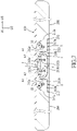
FIG. 2 is a perspective view similar to FIG. 1, illustrating the rotating modules at a closed position and the machine bodies in a folded state;
FIG. 3 is a partly exploded perspective view of FIG. 1;
FIG. 4 is an exploded perspective view of the embodiment;
FIG. 5 is a fragmentary sectional view of the embodiment, the machine bodies and the flexible display, illustrating the rotating modules at the open position;
FIG. 6 is a fragmentary sectional view of the embodiment, the machine bodies and the flexible display, illustrating the rotating modules at the closed position;
FIG. 7 is a fragmentary sectional view of the embodiment, the machine bodies and the flexible display, illustrating a side support plate of each of the rotating modules cooperating with a central support plate to support the flexible display when the rotating modules are at the open position;
FIG. 8 is a fragmentary sectional view of the embodiment, the machine bodies and the flexible display, illustrating the side support plate of each of the rotating modules cooperating with the central support plate to provide a space for receiving a bent portion of the flexible display when the rotating modules are at the closed position;
FIG. 9 is a fragmentary sectional view of the embodiment, the machine bodies and the flexible display, illustrating connections between the central support plate and two synchronizing pieces of the embodiment when the rotating modules are at the open position;
FIG. 10 is a fragmentary sectional view of the embodiment, the machine bodies and the flexible display, illustrating the connections between the central support plate and the two synchronizing pieces when the rotating modules are at the closed position;
FIG. 11 is a fragmentary sectional view, illustrating a torsion unit of each of the rotating modules when the rotating modules are at the open position; and
FIG. 12 is a fragmentary sectional view, illustrating the torsion unit of one of the rotating modules when the rotating modules are at the closed position.
DETAILED DESCRIPTION
Referring to FIGS. 1 to 4, an embodiment of a hinge device 100 according to the disclosure is adapted to be installed between two machine bodies 200 that are mounted with a flexible display 300 so as to form a foldable device. It should be noted that, in the present embodiment, the flexible display 300 is mounted to the machine bodies 200 but not to the hinge device 100, that is, the hinge device 100 only provides support to the flexible display 300, but is not limited thereto.
The hinge device 100 includes a base member 1, two rotating modules 2, a central support plate 3 and two synchronizing pieces 4. It should also be noted that, in other embodiments of the disclosure, the synchronizing pieces 4 may be omitted.
The base member 1 extends in a front-rear direction (D1), and has a plurality of arc-shaped sliding grooves 11 and two first connecting slots 12. The first connecting slots 12 are opposite to each other in the front-rear direction (D1).
The rotating modules 2 are mounted respectively to opposite sides of the base member 1 in a left-right direction (D2), and are adapted for the machine bodies 200 to be mounted respectively thereto. The rotating modules 2 are convertible relative to the base member 1 between an open position (see FIG. 5) and a closed position (see FIG. 6).
When the rotating modules 2 are at the open position, the machine bodies 200 are in an unfolded state (see FIG. 5) such that the flexible display 300 is flat. When the rotating modules 2 are at the closed position, the machine bodies 200 are in a folded state (see FIG. 6) such that the flexible display 300 is folded.
Each of the rotating modules 2 includes a moving frame 21 and a side support plate 22. For each of the rotating modules 2, the moving frame 21 is movable relative to the base member 1, and is adapted for a respective one of the machine bodies 200 to be mounted thereto, and the side support plate 22 is connected between the moving frame 21 and the base member 1, and is drivable by the moving frame 21 to rotate relative to the base member 1 about a plate rotational axis (A1).
Referring to FIGS. 3 to 6, specifically, the moving frame 21 of each of the rotating modules 2 has two moving segments 211, a connecting segment 212 and two shaft members 213. Since the two rotating modules 2 are identical to each other, for the sake of brevity, the following structural description of the moving frame 21 only refers to one of the rotating modules 2.
The moving segments 211 of the moving frame 21 are respectively connected to opposite ends of the base member 1 in the front-rear direction (D1), and are movable relative to the base member 1. The side support plate 22 is disposed between the moving segments 211 of the moving frame 21 and is connected to the connecting segment 212 of the moving frame 21.
Each of the moving segments 211 has a slide slot 211 a and a sliding pole 211 b. The slide slot 211 a of each of the moving segments 211 extends therethrough in the front-rear direction (D1), is elongated in the left-right direction (D2) (see FIGS. 4 and 5), and has an inner end 211 c and an outer end 211 d that are opposite to each other in the left-right direction (D2). The sliding pole 211 b of each of the moving segments 211 extends in the front-rear direction (D1), and is slidably received in a respective one of the arc-shaped sliding grooves 11 of the base member 1.
The connecting segment 212 of the moving frame 21 extends in the front-rear direction (D1), and is connected between the moving segments 211.
Each of the shaft members 213 of the moving frame 21 extends in the front-rear direction (D1), extends movably through the slide slot 211 a of a respective one of the moving segments 211 and into a respective one of the opposite ends of the base member 1, and is connected to the central support plate 3. Each of the shaft members 213 is drivable by the respective one of the moving segments 211 to rotate relative to the base member 1 about a shaft rotational axis (A2) extending in the front-rear direction (D1).
Specifically, each of the shaft members 213 has a sliding portion 213 a and a driving block 213 b. The sliding portion 213 a of each of the shaft members 213 is slidably and non-rotatably received in the slide slot 211 a of the respective one of the moving segments 211. The driving block 213 b of each of the shaft members 213 is sleeved on an end segment of the sliding portion 213 a and has a driving protrusion 213 c that extends in the front-rear direction (D1) and that is spaced apart form the shaft rotational axis (A2).
When each of the rotating modules 2 is at the open position, the sliding portion 213 a of each of the shaft members 213 is disposed in the outer end 211 d of the slide slot 211 a of the respective one of the moving segments 211.
When each of the rotating modules 2 is at the closed position, the sliding portion 213 a of each of the shaft members 213 is disposed in the inner end 211 c of the slide slots 211 a of the respective one of the moving segments 211. In such a manner, when the rotating modules 2 are converted from the open position to the closed position (i.e., the machine bodies 200 are converted from the unfolded state to the folded state), the moving frame 21 of each of the rotating modules 2 rotates relative to the base member 1, and slides slightly out of the base member 1 as each of the shaft members 213 moves from the outer end 211 d of the slide slot 211 a to the inner end 211 c.
It should be noted that, the above-mentioned movement of each of the rotating modules 2, which involves sliding movement and rotation, is a resulting combination of movements of the sliding portions 213 a of the shaft members 213 relative to the slide slots 211 a of the moving segments 211 and movements of the sliding poles 211 b of the moving segments 211 relative to the arc-shaped sliding grooves 11 of the base member 1. That is, configurations of the above-mentioned components (e.g., an extending pattern of the arc-shaped sliding grooves 11 that corresponds to the movements of the sliding poles 211 b) are particularly designed in order to enable the sliding-rotating movement of the rotating modules 2. However, the above-mentioned configurations are not limited to the present embodiment and may be adjusted in other embodiments depending on actual requirements.
Referring to FIGS. 4, 7 and 8, the central support plate 3 extends in the front-rear direction (D1), is disposed above the base member 1 in an up-down direction (D3), and is connected between the rotating modules 2.
Specifically on the position of the central support plate 3, the first connecting slots 12 of the base member 1 are disposed respectively proximate to two ends of the central support plate 3 that are opposite to each other in the front-rear direction (D1). The side support plates 22 of the rotating modules 2 are disposed respectively on opposite sides of the central support plate 3 in the left-right direction (D2). The driving protrusion 213 c of each of the shaft members 213 is disposed at a respective one of the two ends of the central support plate 3 in a manner that the driving protrusions 213 c which are disposed at each of the two ends of the central support plate 3 are aligned with each other in the left-right direction (D2).
The central support plate 3 has a plurality of receiving grooves 31, each of which is disposed proximate to one of the two ends of the central support plate 3, and two second connecting slots 32 which are disposed respectively proximate to the two ends of the central support plate 3.
The driving protrusion 213 c of each of the shaft members 213 is engaged movably with a corresponding one of the receiving grooves 31 such that, during rotation of each of the shaft members 213 relative to the base member 1, the driving protrusion 213 c drives the central support plate 3 to move relative to the base member 1 in the up-down direction (D3) between a supporting position (see FIG. 7) and a receding position (see FIG. 8).
When the central support plate 3 is at the supporting position, the rotating modules 2 are at the open position, and the central support plate 3 is adapted to cooperate with the side support plates 22 to support the flexible display 300 from below.
When the central support plate 3 is at the receding position, the rotating modules 2 are at the closed position, and the central support plate 3 is disposed under the supporting position to provide a display receiving space (S) disposed directly and immediately above the central support plate 3 for receiving a bent portion of the flexible display 300. Specifically, the display receiving space (S) is cooperatively defined by the side support plates 22 of the rotating modules 2 and the central support plate 3.
It should be noted that, as mentioned above, when the rotating modules 2 are converted from the open position to the closed position, the moving frames 21 of the rotating modules 2 slide slightly out of the base member 1. In such a manner, the move frames 21 bring portions of the folded flexible display 300 to move slightly away from the base member 1. As such, movements of the moving frames 21 and the presence of the display receiving space (S) cooperatively prevent the bent portion of the flexible display 300 from being cramped by any nearby components.
It should also be noted that, referring to FIG. 8, a distance between the plate rotational axes (A1) of the side support plates 22 of the rotating modules 2 is greater than a distance between the shaft rotational axes (A2) of the shaft members 213 of the rotating modules 2. As such, when the rotating modules 2 are at the closed position, a width of the display receiving space (S) in the left-right direction (D2) increases downwardly.
In other embodiments of the disclosure, the side support plate 22 of each of the rotating modules 2 may be integrally formed with the moving frame 21 as a single driving component (i.e., the side support plates 22 may be omitted). In these cases, the central support plate 3 is movable between the supporting and receding positions by said driving component.
Referring to FIGS. 4, 9 and 10, the synchronizing pieces 4 are arranged in the front-rear direction (D1), and are disposed respectively proximate to the opposite ends of the central support plate 3. Each of the synchronizing pieces 4 has a first connecting portion and a second connecting portion 42 that are respectively connected to opposite ends of a thin plate-shaped main portion of each of the synchronizing pieces 4.
The first connecting portion 41 of each of the synchronizing pieces 4 is pin-shaped, extends in the left-right direction (D2), and is received in a respective one of the first connecting slots 12 of the base member 1. The second connecting portion 42 of each of the synchronizing pieces 4 is pin-shaped, extends in the left-right direction (D2), is opposite to the first connecting portion 41 in a direction oblique to the front-rear direction (D1), and is received in a respective one of the second connecting slots 32 of the central support plate 3 such that each of the synchronizing pieces 4 is connected between the central support plate 3 and the base member 1.
It should be noted that each of the synchronizing pieces 4 is slidable in one of the first and second connecting slots 12, 32 in the front-rear direction (D1). In the present embodiment, each of the synchronizing pieces 4 is slidable in a respective one of the first and second connecting slots 12, and each of receiving grooves 31 is in spatial communication with a corresponding one of the second connecting slots 32, but is not limited thereto.
By virtue of the connection between the second connecting portion 42 of each of the synchronizing pieces 4 and the central support plate 3, the two ends of the central support plate 3 are maintained constantly at the same level with respect to the base member 1 (i.e., whether the central support plate 3 is in motion or remains stationary), and the driving protrusions 213 c of the shaft members 213, which are disposed at the two ends of the central support plate 3, are thereby maintained at the same level as well. In other words, the rotations of the shaft members 213 are synchronized by the synchronizing pieces 4 and the central support plate 3 and, as a result, the converting movements of the rotating modules 2 between the open and closed positions are also synchronized.
Referring to FIGS. 4, 5, 11 and 12, it should be further noted that, the connecting segment 212 of the moving frame 21 of each of the rotating modules 2 has a maintaining mechanism that maintains each of the rotating modules 2 at at least one predetermined position. In the present embodiment, there are two predetermined positions, which are the open position and the closed position. However, in variations of the embodiment, there might be one, three, or more than three predetermined positions, and the predetermined positions may or may not include any of the open and closed positions.
Specifically on the maintaining mechanism, the connecting segment 212 of the moving frame 21 of each of the rotating modules 2 has a connecting main body 212 a and two torsion units 212 b.
The connecting main body 212 a of each of the rotating modules 2 is connected between the moving segments 211 of the moving frame 21. The torsion units 212 b of each of the rotating modules 2 are spaced apart from each other, are mounted to the connecting main body 212 a, and are connected to the side support plate 22 of a corresponding one of the rotating modules 2. However, in variations of the embodiment, the connecting segment 212 of each of the rotating modules 2 may have only one torsion unit 212 b, or the torsion unit 212 b may be omitted. In the latter case, the connecting main body 212 a is connected directly to the side support plate 22 of the corresponding one of the rotating modules 2.
Each of the torsion units 212 b has a housing 212 c, a pin member 212 d, a driven member 212 e, a pressing piece 212 f and a resilient member 212 g.
The housing 212 c of each of the torsion units 212 b is mounted to the connecting main body 212 a. The pin member 212 d of each of the torsion units 212 b extends fixedly through the housing 212 c. The driven member 212 e of each of the torsion units 212 b is rotatably sleeved on the pin member 212 d, and is partially received in the housing 212 c with a portion thereof extending out of the housing 212 c and connected to the side support plate 22, such that the driven member 212 e is co-rotatable with the side support plate 22 relative to the housing 212 c about a central axis of the pin member 212 d which extends in the front-rear direction (D1).
The pressing piece 212 f of each of the torsion units 212 b is received non-rotatably in the housing 212 c, is slidably sleeved on the pin member 212 d, is slidable relative to the housing 212 c in the front-rear direction (D1), and is disposed adjacent to the driven member 212 e in the front-rear direction (D1).
For each of the torsion units 212 b, the driven member 212 e has a first concave-convex structure 212 h, and the pressing piece 212 f has a second concave-convex structure 212 i. The first and second concave- convex structure 212 h, 212 i face toward each other.
The resilient member 212 g of each of the torsion units 212 b is received in the housing 212 c, is sleeved on the pin member 212 d with opposite ends thereof abutting respectively against an inner surface of the housing 212 c and the pressing piece 212 f, such that the resilient member 212 g biases the pressing piece 212 f to contact the driven member 212 e for maintaining contact between the first and second concave- convex structures 212 h, 212 i.
When the rotating modules 2 are at one of the predetermined positions (i.e., the open position or the closed position), the first and second concave- convex structures 212 h, 212 i of each of the rotating modules 2 are complementary in shape with each other (i.e., the first and second concave- convex structures 212 h, 212 i are engaged with each other), so as to maintain the rotating modules 2 at the one of the predetermined positions. That is, the rotating modules 2 at the one of the predetermined positions are maintained stationary.
When the rotating modules 2 are moved away from the one of the predetermined positions, rotation of the driven member 212 e relative to the pressing piece 212 f causes the first concave-convex structure 212 h to move relative to the second concave-convex structure 212 i and pushes the same away (at this moment, the first and second concave- convex structures 212 h, 212 i are not engaged with each other). As such, the pressing piece 212 f moves away from the driven member 212 e and presses the resilient member 212 g against the inner surface of the housing 212 c. By virtue of the resilient member 212 g, the pressing piece 212 f is disposed to push constantly against the driven member 212 e, and thus the rotating modules 2 at any position other than the predetermined positions are inclined to move toward one of the predetermined positions. In other words, the first and second concave- convex structures 212 h, 212 i are disposed to be engaged with each other, and the rotating modules 2 are disposed to be maintained at one of the predetermined positions.
In summary, by virtue of the configurations of the rotating modules 2 of the hinge device 100, the central support plate 3 of the hinge device 100 is movable from the supporting position to the receding position so as to provide the display receiving space (S) for the bent portion of the flexible display 300, which prevents the bent portion of the flexible display 300 from being cramped and damaged by any surrounding components.
In the description above, for the purposes of explanation, numerous specific details have been set forth in order to provide a thorough understanding of the embodiment. It will be apparent, however, to one skilled in the art, that one or more other embodiments may be practiced without some of these specific details. It should also be appreciated that reference throughout this specification to “one embodiment,” “an embodiment,” an embodiment with an indication of an ordinal number and so forth means that a particular feature, structure, or characteristic may be included in the practice of the disclosure. It should be further appreciated that in the description, various features are sometimes grouped together in a single embodiment, figure, or description thereof for the purpose of streamlining the disclosure and aiding in the understanding of various inventive aspects, and that one or more features or specific details from one embodiment may be practiced together with one or more features or specific details from another embodiment, where appropriate, in the practice of the disclosure.
While the disclosure has been described in connection with what is considered the exemplary embodiment, it is understood that this disclosure is not limited to the disclosed embodiment but is intended to cover various arrangements included within the spirit and scope of the broadest interpretation so as to encompass all such modifications and equivalent arrangements.