US11412334B2 - Contralateral sound capture with respect to stimulation energy source - Google Patents
Contralateral sound capture with respect to stimulation energy source Download PDFInfo
- Publication number
- US11412334B2 US11412334B2 US14/061,410 US201314061410A US11412334B2 US 11412334 B2 US11412334 B2 US 11412334B2 US 201314061410 A US201314061410 A US 201314061410A US 11412334 B2 US11412334 B2 US 11412334B2
- Authority
- US
- United States
- Prior art keywords
- bone conduction
- recipient
- sound
- behind
- ear
- Prior art date
- Legal status (The legal status is an assumption and is not a legal conclusion. Google has not performed a legal analysis and makes no representation as to the accuracy of the status listed.)
- Active, expires
Links
Images


Classifications
-
- H—ELECTRICITY
- H04—ELECTRIC COMMUNICATION TECHNIQUE
- H04R—LOUDSPEAKERS, MICROPHONES, GRAMOPHONE PICK-UPS OR LIKE ACOUSTIC ELECTROMECHANICAL TRANSDUCERS; ELECTRIC HEARING AIDS; PUBLIC ADDRESS SYSTEMS
- H04R25/00—Electric hearing aids
- H04R25/55—Electric hearing aids using an external connection, either wireless or wired
- H04R25/552—Binaural
-
- H—ELECTRICITY
- H04—ELECTRIC COMMUNICATION TECHNIQUE
- H04R—LOUDSPEAKERS, MICROPHONES, GRAMOPHONE PICK-UPS OR LIKE ACOUSTIC ELECTROMECHANICAL TRANSDUCERS; ELECTRIC HEARING AIDS; PUBLIC ADDRESS SYSTEMS
- H04R2460/00—Details of hearing devices, i.e. of ear- or headphones covered by H04R1/10 or H04R5/033 but not provided for in any of their subgroups, or of hearing aids covered by H04R25/00 but not provided for in any of its subgroups
- H04R2460/13—Hearing devices using bone conduction transducers
-
- H—ELECTRICITY
- H04—ELECTRIC COMMUNICATION TECHNIQUE
- H04R—LOUDSPEAKERS, MICROPHONES, GRAMOPHONE PICK-UPS OR LIKE ACOUSTIC ELECTROMECHANICAL TRANSDUCERS; ELECTRIC HEARING AIDS; PUBLIC ADDRESS SYSTEMS
- H04R25/00—Electric hearing aids
- H04R25/60—Mounting or interconnection of hearing aid parts, e.g. inside tips, housings or to ossicles
- H04R25/604—Mounting or interconnection of hearing aid parts, e.g. inside tips, housings or to ossicles of acoustic or vibrational transducers
- H04R25/606—Mounting or interconnection of hearing aid parts, e.g. inside tips, housings or to ossicles of acoustic or vibrational transducers acting directly on the eardrum, the ossicles or the skull, e.g. mastoid, tooth, maxillary or mandibular bone, or mechanically stimulating the cochlea, e.g. at the oval window
-
- H—ELECTRICITY
- H04—ELECTRIC COMMUNICATION TECHNIQUE
- H04R—LOUDSPEAKERS, MICROPHONES, GRAMOPHONE PICK-UPS OR LIKE ACOUSTIC ELECTROMECHANICAL TRANSDUCERS; ELECTRIC HEARING AIDS; PUBLIC ADDRESS SYSTEMS
- H04R25/00—Electric hearing aids
- H04R25/60—Mounting or interconnection of hearing aid parts, e.g. inside tips, housings or to ossicles
- H04R25/607—Mounting or interconnection of hearing aid parts, e.g. inside tips, housings or to ossicles of earhooks
Definitions
- Hearing loss which may be due to many different causes, is generally of two types: conductive and sensorineural.
- Sensorineural hearing loss is due to the absence or destruction of the hair cells in the cochlea that transduce sound signals into nerve impulses.
- Various hearing prostheses are commercially available to provide individuals suffering from sensorineural hearing loss with the ability to perceive sound.
- cochlear implants use an electrode array implanted in the cochlea of a recipient to bypass the mechanisms of the ear. More specifically, an electrical stimulus is provided via the electrode array to the auditory nerve, thereby causing a hearing percept.
- Conductive hearing loss occurs when the normal mechanical pathways that provide sound to hair cells in the cochlea are impeded, for example, by damage to the ossicular chain or the ear canal. Individuals suffering from conductive hearing loss may retain some form of residual hearing because the hair cells in the cochlea may remain undamaged.
- Hearing aids rely on principles of air conduction to transmit acoustic signals to the cochlea.
- a hearing aid typically uses an arrangement positioned in the recipient's ear canal or on the outer ear to amplify a sound received by the outer ear of the recipient. This amplified sound reaches the cochlea causing motion of the perilymph and stimulation of the auditory nerve.
- Bone conduction devices In contrast to hearing aids, which rely primarily on the principles of air conduction, certain types of hearing prostheses commonly referred to as bone conduction devices, convert a received sound into vibrations. The vibrations are transferred through the skull to the cochlea causing generation of nerve impulses, which result in the perception of the received sound. Bone conduction devices are suitable to treat a variety of types of hearing loss and may be suitable for individuals who cannot derive sufficient benefit from acoustic hearing aids, cochlear implants, etc, or for individuals who suffer from stuttering problems.
- a hearing prosthesis system comprising a sound capture device configured to capture a sound and generate a signal based on the captured sound and a vibratory portion configured to vibrate in response to the signal to evoke a hearing percept via bone conduction, wherein the system is configured to capture the sound on a first side of a recipient where the sound capture device is located and transfer the signal to a second side of the recipient where the vibratory portion is located.
- a hearing prosthesis system as described above and/or below, wherein the system is configured to evoke hearing percepts via bone conduction at only high-frequencies.
- a method comprising capturing sound at a first side of a recipient, and evoking a hearing percept via bone conduction with energy originating on an opposite side of the recipient based on the captured sound.
- a method comprising imparting vibratory energy into bone proximate an at least partially functioning cochlea of a recipient based on sound captured on a side of the recipient opposite the at least partially functioning cochlea; and evoking a hearing percept via bone conduction due to the imparted vibratory energy.
- a behind-the-ear device comprising a vibratory portion configured to vibrate in response to an audio signal to evoke a hearing percept via bone conduction, and a speaker portion configured to evoke a hearing percept via an acoustic pressure wave, wherein the behind-the-ear device is a totally external device.
- the device is configured to receive a wireless signal originating from a component remote from the device, wherein the wireless signal corresponds to the audio signal.
- a method comprising imparting vibratory energy into bone proximate an at least partially functioning cochlea of a recipient based on sound captured on a side of the recipient opposite the at least partially functioning cochlea; and evoking a hearing percept due to the imparted vibratory energy.
- the at least partially functioning cochlea is an effectively fully functioning cochlea.
- a cochlea of the recipient on the side of the recipient opposite the at least partially functioning cochlea is less functional than the at least partially functioning cochlea.
- the evoked hearing percept via bone conduction is based on ambient sound having high frequency.
- a method as detailed above and/or below wherein the evoked hearing percept via bone conduction does not evoke a hearing percept corresponding to a low frequency.
- a method as detailed above and/or below wherein the evoked hearing percept via bone conduction is evoked utilizing a device configured to not evoke a hearing percept corresponding to a low frequency.
- FIG. 1A is a perspective view of an exemplary bone conduction device in which at least some embodiments can be implemented;
- FIG. 1B is a perspective view of an alternate exemplary bone conduction device in which at least some embodiments can be implemented;
- FIG. 1C is a perspective view of an alternate exemplary bone conduction device in which at least some embodiments can be implemented;
- FIG. 2 is a schematic diagram conceptually illustrating a removable component of a percutaneous bone conduction device in accordance with at least some exemplary embodiments
- FIG. 3 is a schematic diagram conceptually illustrating a passive transcutaneous bone conduction device in accordance with at least some exemplary embodiments
- FIG. 4 is a schematic diagram conceptually illustrating an active transcutaneous bone conduction device in accordance with at least some exemplary embodiments
- FIG. 5A is a schematic diagram conceptually illustrating a behind-the-ear (BTE) device corresponding to a passive transcutaneous bone conduction device;
- BTE behind-the-ear
- FIG. 5B is a schematic diagram conceptually illustrating a rear view of a portion of the behind-the-ear (BTE) device of FIG. 5B ;
- BTE behind-the-ear
- FIG. 6A is a high-level functional diagram of an exemplary embodiment
- FIG. 6B is a medium-level functional diagram of an exemplary embodiment
- FIG. 7A is a diagram of an exemplary alternate embodiment usable with the embodiments of FIGS. 6A and 6B ;
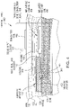
- FIG. 7B is a schematic diagram conceptually illustrating an alternate behind-the-ear (BTE) device corresponding to a passive transcutaneous bone conduction device that also includes an exemplary speaker; and
- BTE behind-the-ear
- FIG. 8 is an exemplary flow chart of an exemplary method according to an exemplary embodiment.
- FIG. 1A is a perspective view of a bone conduction device 100 A in which embodiments may be implemented. As shown, the recipient has an outer ear 101 , a middle ear 102 and an inner ear 103 . Elements of outer ear 101 , middle ear 102 and inner ear 103 are described below, followed by a description of bone conduction device 100 .
- outer ear 101 comprises an auricle 105 and an ear canal 106 .
- a sound wave or acoustic pressure 107 is collected by auricle 105 and channeled into and through ear canal 106 .
- Disposed across the distal end of ear canal 106 is a tympanic membrane 104 which vibrates in response to acoustic wave 107 .
- This vibration is coupled to oval window or fenestra ovalis 210 through three bones of middle ear 102 , collectively referred to as the ossicles 111 and comprising the malleus 112 , the incus 113 and the stapes 114 .
- the ossicles 111 of middle ear 102 serve to filter and amplify acoustic wave 107 , causing oval window 210 to vibrate. Such vibration sets up waves of fluid motion within cochlea 139 . Such fluid motion, in turn, activates hair cells (not shown) that line the inside of cochlea 139 . Activation of the hair cells causes appropriate nerve impulses to be transferred through the spiral ganglion cells and auditory nerve 116 to the brain (not shown), where they are perceived as sound.
- FIG. 1A also illustrates the positioning of bone conduction device 100 A relative to outer ear 101 , middle ear 102 and inner ear 103 of a recipient of device 100 .
- bone conduction device 100 is positioned behind outer ear 101 of the recipient and comprises a sound input element 126 A to receive sound signals.
- Sound input element may comprise, for example, a microphone, telecoil, etc.
- sound input element 126 A may be located, for example, on or in bone conduction device 100 A, or on a cable extending from bone conduction device 100 A.
- bone conduction device 100 A comprises an operationally removable component and a bone conduction implant.
- the operationally removable component is operationally releasably coupled to the bone conduction implant.
- operationally releasably coupled it is meant that it is releasable in such a manner that the recipient can relatively easily attach and remove the operationally removable component during normal use of the bone conduction device 100 A.
- Such releasable coupling is accomplished via a coupling assembly of the operationally removable component and a corresponding mating apparatus of the bone conduction implant, as will be detailed below. This as contrasted with how the bone conduction implant is attached to the skull, as will also be detailed below.
- the operationally removable component includes a sound processor (not shown), a vibrating electromagnetic actuator and/or a vibrating piezoelectric actuator and/or other type of actuator (not shown—which are sometimes referred to herein as a species of the genus vibrator) and/or various other operational components, such as sound input device 126 A.
- the operationally removable component is sometimes referred to herein as a vibrator unit.
- sound input device 126 A e.g., a microphone
- the sound processor generates control signals which cause the actuator to vibrate.
- the actuator converts the electrical signals into mechanical motion to impart vibrations to the recipient's skull.
- the operationally removable component of the bone conduction device 100 A further includes a coupling assembly 240 configured to operationally removably attach the operationally removable component to a bone conduction implant (also referred to as an anchor system and/or a fixation system) which is implanted in the recipient.
- a bone conduction implant also referred to as an anchor system and/or a fixation system
- coupling assembly 240 is coupled to the bone conduction implant (not shown) implanted in the recipient in a manner that is further detailed below with respect to exemplary embodiments of the bone conduction implant.
- an exemplary bone conduction implant may include a percutaneous abutment attached to a bone fixture via a screw, the bone fixture being fixed to the recipient's skull bone 136 .
- the abutment extends from the bone fixture which is screwed into bone 136 , through muscle 134 , fat 128 and skin 232 so that the coupling assembly may be attached thereto.
- a percutaneous abutment provides an attachment location for the coupling assembly that facilitates efficient transmission of mechanical force.
- embodiments include active transcutaneous bone conduction systems utilizing the electromagnetic actuators disclosed herein and variations thereof where at least one active component (e.g. the electromagnetic actuator) is implanted beneath the skin.
- embodiments also include passive transcutaneous bone conduction systems utilizing the electromagnetic actuators disclosed herein and variations thereof where no active component (e.g., the electromagnetic actuator) is implanted beneath the skin (it is instead located in an external device), and the implantable part is, for instance a magnetic pressure plate.
- Some embodiments of the passive transcutaneous bone conduction systems are configured for use where the vibrator (located in an external device) containing the electromagnetic actuator is held in place by pressing the vibrator against the skin of the recipient.
- an implantable holding assembly is implanted in the recipient that is configured to press the bone conduction device against the skin of the recipient.
- the vibrator is held against the skin via a magnetic coupling (magnetic material and/or magnets being implanted in the recipient and the vibrator having a magnet and/or magnetic material to complete the magnetic circuit, thereby coupling the vibrator to the recipient).
- FIG. 1B is a perspective view of a transcutaneous bone conduction device 100 B in which embodiments can be implemented.
- FIG. 1A also illustrates the positioning of bone conduction device 100 B relative to outer ear 101 , middle ear 102 and inner ear 103 of a recipient of device 100 .
- bone conduction device 100 is positioned behind outer ear 101 of the recipient.
- Bone conduction device 100 B comprises an external component 140 B and implantable component 150 .
- the bone conduction device 100 B includes a sound input element 126 B to receive sound signals.
- sound input element 126 B may comprise, for example, a microphone, telecoil, etc.
- sound input element 126 B may be located, for example, on or in bone conduction device 100 B, on a cable or tube extending from bone conduction device 100 B, etc.
- sound input element 126 B may be subcutaneously implanted in the recipient, or positioned in the recipient's ear. Sound input element 126 B may also be a component that receives an electronic signal indicative of sound, such as, for example, from an external audio device. For example, sound input element 126 B may receive a sound signal in the form of an electrical signal from an MP3 player electronically connected to sound input element 126 B.
- Bone conduction device 100 B comprises a sound processor (not shown), an actuator (also not shown) and/or various other operational components.
- sound input device 126 B converts received sounds into electrical signals. These electrical signals are utilized by the sound processor to generate control signals that cause the actuator to vibrate. In other words, the actuator converts the electrical signals into mechanical vibrations for delivery to the recipient's skull.
- a fixation system 162 may be used to secure implantable component 150 to skull 136 .
- fixation system 162 may be a bone screw fixed to skull 136 , and also attached to implantable component 150 .
- bone conduction device 100 B can be a passive transcutaneous bone conduction device. That is, no active components, such as the actuator, are implanted beneath the recipient's skin 132 .
- the active actuator is located in external component 140 B, and implantable component 150 includes a magnetic plate, as will be discussed in greater detail below.
- the magnetic plate of the implantable component 150 vibrates in response to vibration transmitted through the skin, mechanically and/or via a magnetic field, that are generated by an external magnetic plate.
- bone conduction device 100 B can be an active transcutaneous bone conduction device where at least one active component, such as the actuator, is implanted beneath the recipient's skin 132 and is thus part of the implantable component 150 .
- active component such as the actuator
- external component 140 B may comprise a sound processor and transmitter
- implantable component 150 may comprise a signal receiver and/or various other electronic circuits/devices.
- FIG. 1C is a perspective view of a transcutaneous bone conduction device 100 C in which embodiments of the present invention can be implemented, worn by a recipient. As shown, bone conduction device 100 C is positioned behind outer ear 101 of the recipient. Bone conduction device 100 C comprises an external component 140 C in the form of a behind-the-ear (BTE) device.
- BTE behind-the-ear
- External component 140 C typically comprises one or more sound input elements 126 C, such as a microphone, for detecting and capturing sound, a sound processing unit (not shown) and a power source (not shown).
- the external component 140 C includes an actuator (not shown), which in the embodiment of FIG. 1C , is located within the body of the BTE device, although in other embodiments, the actuator may be located remote from the BTE device (or other component of the external component 140 C having a sound input element, a sound processing unit and/or a power source, etc.).
- the sound processing unit of the external component 140 C processes the output of the sound input element 126 C, which is typically in the form of an electrical signal.
- the processing unit generates control signals that cause the actuator to vibrate.
- the actuator converts the electrical signals into mechanical vibrations for delivery to the recipient's skull.
- bone conduction device 100 C is a passive transcutaneous bone conduction device. That is, no active components, such as the actuator, are implanted beneath the recipient's skin 132 . In such an arrangement, as will be described below, the active actuator is located in external component 140 .
- the embodiment of FIG. 1C is depicted as having no implantable component. That is, vibrations generated by the actuator are transferred from the actuator, into the skin directly from the actuator and/or through a housing of the BTE device, through the skin of the recipient, and into the bone of the recipient, thereby evoking a hearing percept without passing through an implantable component. In this regard, it is a totally external bone conduction device.
- FIG. 2 is an embodiment of a bone conduction device 200 in accordance with an embodiment corresponding to that of FIG. 1A , illustrating use of a percutaneous bone conduction device.
- Bone conduction device 200 corresponding to, for example, element 100 A of FIG. 1A , includes a housing 242 , a vibrating electromagnetic actuator 250 , a coupling assembly 240 that extends from housing 242 and is mechanically linked to vibrating electromagnetic actuator 250 .
- vibrating electromagnetic actuator 250 and coupling assembly 240 form a vibrating electromagnetic actuator-coupling assembly 280 .
- Vibrating electromagnetic actuator-coupling assembly 280 is suspended in housing 242 by spring 244 .
- spring 244 is connected to coupling assembly 240 , and vibrating electromagnetic actuator 250 is supported by coupling assembly 240 .
- spring 244 is connected to coupling assembly 240
- vibrating electromagnetic actuator 250 is supported by coupling assembly 240 .
- disclosure of a spring herein also includes disclosure of any other type of resilient element that can be utilized to practice the respective embodiment and/or variations thereof.
- FIG. 3 depicts an exemplary embodiment of a transcutaneous bone conduction device 300 according to an embodiment that includes an external device 340 (corresponding to, for example, element 140 B of FIG. 1B ) and an implantable component 350 (corresponding to, for example, element 150 of FIG. 1B ).
- the transcutaneous bone conduction device 300 of FIG. 3 is a passive transcutaneous bone conduction device in that a vibrating electromagnetic actuator 342 is located in the external device 340 .
- Vibrating electromagnetic actuator 342 is located in housing 344 of the external component, and is coupled to plate 346 .
- Plate 346 may be in the form of a permanent magnet and/or in another form that generates and/or is reactive to a magnetic field, or otherwise permits the establishment of magnetic attraction between the external device 340 and the implantable component 350 sufficient to hold the external device 340 against the skin of the recipient.
- the vibrating electromagnetic actuator 342 is a device that converts electrical signals into vibration.
- sound input element 126 converts sound into electrical signals.
- the transcutaneous bone conduction device 300 provides these electrical signals to vibrating electromagnetic actuator 342 , or to a sound processor (not shown) that processes the electrical signals, and then provides those processed signals to vibrating electromagnetic actuator 342 .
- the vibrating electromagnetic actuator 342 converts the electrical signals (processed or unprocessed) into vibrations. Because vibrating electromagnetic actuator 342 is mechanically coupled to plate 346 , the vibrations are transferred from the vibrating electromagnetic actuator 342 to plate 346 .
- Implanted plate assembly 352 is part of the implantable component 350 , and is made of a ferromagnetic material that may be in the form of a permanent magnet, that generates and/or is reactive to a magnetic field, or otherwise permits the establishment of a magnetic attraction between the external device 340 and the implantable component 350 sufficient to hold the external device 340 against the skin of the recipient. Accordingly, vibrations produced by the vibrating electromagnetic actuator 342 of the external device 340 are transferred from plate 346 across the skin to plate 355 of plate assembly 352 . This can be accomplished as a result of mechanical conduction of the vibrations through the skin, resulting from the external device 340 being in direct contact with the skin and/or from the magnetic field between the two plates. These vibrations are transferred without penetrating the skin with a solid object such as an abutment as detailed herein with respect to a percutaneous bone conduction device.
- the implanted plate assembly 352 is substantially rigidly attached to a bone fixture 341 in this embodiment.
- Plate screw 356 is used to secure plate assembly 352 to bone fixture 341 .
- the portions of plate screw 356 that interface with the bone fixture 341 substantially correspond to an abutment screw discussed in some additional detail below, thus permitting plate screw 356 to readily fit into an existing bone fixture used in a percutaneous bone conduction device.
- plate screw 356 is configured so that the same tools and procedures that are used to install and/or remove an abutment screw (described below) from bone fixture 341 can be used to install and/or remove plate screw 356 from the bone fixture 341 (and thus the plate assembly 352 ).
- FIG. 4 depicts an exemplary embodiment of a transcutaneous bone conduction device 400 according to another embodiment that includes an external device 440 (corresponding to, for example, element 140 B of FIG. 1B ) and an implantable component 450 (corresponding to, for example, element 150 of FIG. 1B ).
- the transcutaneous bone conduction device 400 of FIG. 4 is an active transcutaneous bone conduction device in that the vibrating electromagnetic actuator 452 is located in the implantable component 450 .
- a vibratory element in the form of vibrating electromagnetic actuator 452 is located in housing 454 of the implantable component 450 .
- the vibrating electromagnetic actuator 452 is a device that converts electrical signals into vibration.
- External component 440 includes a sound input element 126 that converts sound into electrical signals.
- the transcutaneous bone conduction device 400 provides these electrical signals to vibrating electromagnetic actuator 452 , or to a sound processor (not shown) that processes the electrical signals, and then provides those processed signals to the implantable component 450 through the skin of the recipient via a magnetic inductance link.
- a transmitter coil 442 of the external component 440 transmits these signals to implanted receiver coil 456 located in housing 458 of the implantable component 450 .
- Components (not shown) in the housing 458 such as, for example, a signal generator or an implanted sound processor, then generate electrical signals to be delivered to vibrating electromagnetic actuator 452 via electrical lead assembly 460 .
- the vibrating electromagnetic actuator 452 converts the electrical signals into vibrations.
- the vibrating electromagnetic actuator 452 is mechanically coupled to the housing 454 .
- Housing 454 and vibrating electromagnetic actuator 452 collectively form a vibratory apparatus 453 .
- the housing 454 is substantially rigidly attached to bone fixture 341 .
- FIG. 5A there is a device 540 in the form of a behind-the-ear device, corresponding to the device 140 C described above in FIG. 1C .
- BTE device 540 includes one or more microphones 126 , and may further include an audio signal jack 510 under a cover 520 on the spine 530 of BTE device 540 .
- FIG. 5A further depicts battery 552 and ear hook 590 removably attached to spine 530 .
- FIG. 5B is a rear perspective view of the spine 530 of the BTE device 540 .
- the BTE device 540 includes a vibratory apparatus configured to evoke a hearing percept via passive transcutaneous bone conduction.
- Actuator 542 is shown located within the spine 330 of BTE device 542 .
- Actuator 542 is a vibratory apparatus, and can be an electromagnetic actuator and/or a piezoelectric actuator and/or another type of actuator that can enable bone conduction.
- Actuator 542 is coupled to the sidewalls 546 of the spine 530 via couplings 543 which are configured to (i) transfer vibrations generated by actuator 542 to the sidewalls 546 , from which those vibrations are transferred to skin 132 .
- the sidewalls 546 form at least part of a housing of spine 530 .
- the housing hermetically seals the interior of the spine 530 from the external environment.
- FIG. 5B depicts adhesives 555 located on the sidewalls 546 of the BTE device 540 .
- Adhesives 555 form coupling portions that are respectively configured to removably adhere the BTE device 540 to the recipient via adhesion at the locations of the adhesives 555 . This adherence being in addition to that which might be provided by the presence of the earhook 590 and/or any grasping phenomenon resulting from the auricle 105 of the outer ear and the skin overlying the mastoid bone of the recipient.
- FIG. 5B is depicted with adhesives 555 located on both sides of the BTE device.
- adhesives 555 located on both sides of the BTE device.
- this permits the adherence properties detailed herein and/or variations thereof to be achieved regardless of whether the recipient wears the BTE device on the left side (in accordance with that depicted in FIG. 5A ) or the right side (or wears two BTE devices).
- BTE device 540 includes adhesive only on one side (the side appropriate for the side on which the recipient intends to wear the BTE device 540 ).
- An embodiment of a BTE device includes a dual-side compatible BTE bone conduction device, as will be detailed below.
- the adhesives 555 are depicted in FIG. 5B in an exaggerated manner so as to be more easily identified.
- the adhesives 555 are double sided tape, where one side of the tape is protected by a barrier, such as a silicone paper, that is removed from the skin-side of the double-sided tape in relatively close temporal proximity to the placement of the BTE device 540 on the recipient.
- adhesives 555 are glue or the like.
- the adhesives 555 are glue, the glue may be applied in relatively close temporal proximity to the placement of the BTE device 540 on the recipient. Such application may be applied by the recipient to the spine 530 , in an exemplary embodiment.
- various teachings detailed herein and/or variations thereof can be applicable to the various embodiments of FIGS. 2-5B and/or variations thereof.
- the various teachings detailed herein and/or variations thereof can be applied to the various embodiments of FIGS. 2-5B to obtain a hearing prosthesis where a vibrating actuator or the like generates vibrations in response to a sound captured by sound capture devices of the various embodiments that are ultimately transmitted to bone of a recipient in a manner that at least effectively evokes hearing percept.
- vibrations are such that a typical human between 18 years old and 40 years old having a fully functioning cochlea receiving such vibrations, where the vibrations communicate speech, would be able to understand the speech communicated by those vibrations in a manner sufficient to carry on a conversation provided that those adult humans are fluent in the language forming the basis of the speech. That said, it is noted that embodiments can also effectively evoke a hearing percept in humans younger than 18 years old and older than 40 years old and/or with humans without a fully functioning cochlea and/or in humans that are not completely fluent in the language forming the basis of the speech. In other words, the aforementioned population of 18 to 40 year olds is provided by way of example and not by way of limitation.
- one or more or all of the above detailed bone conduction devices and/or variations thereof can be utilized in at least some embodiments. That said, in at least some exemplary embodiments, the sound capture devices of the bone conduction devices may be arranged in a manner different than that detailed above and or additional sound capture devices may be utilized with those devices. Some exemplary embodiments that utilize these variations will be detailed below.
- any bone conduction device detailed herein and/or variation thereof can be substituted for any specified bone conduction device that is indicated herein for use in a method, and apparatus, and/or system.
- FIG. 6A depicts a high-level functional diagram of an exemplary system 600 applied to a recipient 999 (the view is a top view—that is a view looking downward onto the recipient's head), with left and right auricle 110 L and 110 R, respectively.
- the embodiment of FIG. 6A depicts one of many applications of the teachings detailed herein and/or variations thereof with respect to human physiology.
- the embodiment of FIG. 6A is described in terms of the utilization of two behind-the-ear devices, it is to be noted that in alternative embodiments, the teachings detailed herein and/or variations thereof can be implemented at other locations on the human body, as will be further described below.
- System 600 includes a first prosthetic device 610 corresponding to a BTE device configured to capture sound.
- the first prostatic device 610 includes a sound capture device 626 configured to capture sound and generate a signal based on the captured sound.
- the sound capture device 626 is a traditional microphone that receives sound pressure waves corresponding to an ambient noise (e.g. a speaker's voice) and transduces the sound pressure waves into an electrical signal or an optical signal, etc.
- System 600 also includes a second prosthetic device 640 also corresponding to a BTE device. This second device is configured to evoke a hearing percept utilizing bone conduction as the principle of operation based on the captured sound captured by the first prosthetic device 600 .
- the first device 610 and the second device 640 are configured to be in communication with one another (at least one way communication, although in alternate embodiments there can be two-way communication between the devices).
- the system 600 is configured to capture sound on a first side of the recipient and transfer a signal that is based on that captured sound to a second side the recipient where the system transduces that transferred signal or a signal based on that signal into vibratory energy to evoke a hearing percept based on bone conduction.
- FIG. 6B depicts a medium-level functional diagram of the system 600 of FIG. 6A .
- ambient sound represented by signal 107 is received by the sound capture device 626 of device 610 .
- This captured sound is transduced by device 610 (e.g., by microphone 626 ) and the transduced signal is provided to transmitter 612 (directly and/or indirectly—another signal based on the transduced signal can be provided to transmitter 612 in some embodiments).
- Device 610 outputs a signal 620 (which can be electromagnetic signal, and optical signal, or any other signal that will enable the teachings detailed herein and are variations thereof to be practiced) via transmitter 612 , which is received by transmitter 642 of device 640 .
- a signal 620 which can be electromagnetic signal, and optical signal, or any other signal that will enable the teachings detailed herein and are variations thereof to be practiced
- Device 640 utilizes the content of this signal to generate vibrational output 644 via vibrational actuator 643 to evoke a hearing percept via bone conduction in a manner corresponding to that of the bone conduction device of FIGS. 5A-B , although in other embodiments, it can be corresponding to one or more of the other or all of the bone conduction devices detailed herein and/or variations thereof.
- device 640 corresponds to any of the bone conduction devices detailed herein and/or variations thereof, with the exception that it includes a transmitter 642 that receives a signal indicative of sound captured by another device (instead of its own sound capture device) and uses that received signal to evoke a hearing percept based on bone conduction device.
- system 600 further includes a signal relay which can be positioned between device 610 and device 640 . More particularly, in an exemplary embodiment, there can be some scenarios where there is utilitarian value in ensuring that the signal transmitted from transmitter 612 is of relatively low-power, at least in scenarios where the signal 620 is a radio frequency signal/electromagnetic signal. In some embodiments, this low-power may not be enough to ensure that the signal 620 reaches device 640 from device 610 . Accordingly, a relay can be positioned that receives the signal 620 from device 610 , and transfers that signal or a new signal based on that received signal to device 640 .
- the relay can amplify the received signal and/or subject the received signal to further signal processing prior to relaying the signal to device 640 .
- the term relay includes both passing the signal through in a modified and/or unmodified state, as well as generating a new signal based on the received signal.
- the relay can be located on a necklace of the like located around the recipient's neck.
- the relay can be located at any position that can enable the teachings detailed herein and/or variations thereof to be practiced.
- devices 610 and 640 are non-invasive prosthetic devices, such as BTE devices (e.g., device 610 can correspond to a BTE device having the functionality of a sound capture device (it can have additional functionality (e.g., it can correspond to the embodiment of FIG. 1C ))), and device 640 can correspond to the BTE device of FIG. 1C (with or without the sound capture device thereof), which, as noted above, corresponds to a passive transcutaneous bone conduction device where the vibratory portion that evokes a hearing percept via bone conduction is part of the BTE device. Accordingly, in an exemplary embodiment, the hearing perceives a system 600 that is a totally external hearing prosthesis system.
- BTE devices e.g., device 610 can correspond to a BTE device having the functionality of a sound capture device (it can have additional functionality (e.g., it can correspond to the embodiment of FIG. 1C )
- device 640 can correspond to the BTE device of FIG. 1C (with or without the sound capture device thereof), which
- devices 610 and/or 640 can be minimally invasive devices such as, for example, in-the-ear canal (ITE) devices (device 610 can include an in-the-ear canal sound capture device and/or device 640 can include an in-the-ear canal bone conduction device). Still further, devices 610 and 640 can be invasive devices, such as by way of example only and not by way of limitation, an implantable microphone with respect to device 610 , and, with respect to device 640 , any of the bone conduction devices of FIGS. 2, 3 and/or 4 or variations thereof. Alternatively, in an exemplary embodiment, device 610 can be any of the bone conduction devices of FIGS.
- ITE in-the-ear canal
- devices 610 and 640 can be invasive devices, such as by way of example only and not by way of limitation, an implantable microphone with respect to device 610 , and, with respect to device 640 , any of the bone conduction devices of FIGS. 2, 3 and/or 4 or variations thereof.
- device 610 can be any
- the vibratory component of device 610 can be disabled or otherwise inactive in at least some instances.
- Device 640 can be any of the bone conduction devices of FIGS. 2, 3, 4 and/or 5A -B, and has the additional functionality to receive a signal including data based on the captured sound captured by device 610 .
- the sound capture device of such a device can be disabled or otherwise inoperative or the output can be disregard or otherwise not used in some scenarios of use.
- device 640 is a percutaneous bone conduction device where the vibratory portion that evokes a hearing percept via bone conduction is part of the percutaneous bone conduction device.
- device 640 is an active or passive transcutaneous bone conduction device where the vibratory portion that evokes a hearing percept via bone conduction is part of the active or passive transcutaneous bone conduction device, respectively.
- both device 640 and device 610 correspond to the bone conduction device of the embodiment of FIGS. 1C / 5 A-B.
- the bone conduction functionality of device 610 if device 610 corresponds to the embodiment of FIG. 1C ) is disabled or otherwise does not respond to sounds captured by the respective sound capture device, and, in at least some embodiments, the sound capture functionality of device 640 (if device 640 corresponds to the embodiment of FIG. 1C ) is disabled or otherwise is not utilized to evoke a hearing percept by that device (device 640 ).
- the bone conduction devices are configured to be in communication with one another (at least one way communication, although in other embodiments two way communication), in accordance with the functional diagram of FIG. 6B .
- communication between device 610 and device 640 is accomplished by communication link 620 (referred to also as signal 620 ).
- communication link 620 is a wireless communication link.
- communication link 620 can be a wired link (e.g. electrical leads, a fiber-optic communication system, etc.). Any device, system, and our method that will enable device 610 to communicate with device 640 to practice the teachings detailed herein and are variations thereof can be utilized in at least some embodiments.
- FIG. 7A depicts an alternate embodiment of a prosthetic device usable in system 600 . More particularly, FIG. 7A depicts device 740 , which can replace device 640 in system 600 . That is, in an exemplary embodiment, there is a system 600 that corresponds to that detailed above, except that device 640 is replaced with device 740 .
- Device 740 can correspond to any of the bone conduction devices detailed above with respect to FIGS. 2, 3 , and/or 5 A-B, except that it further includes transducer 745 which corresponds to a speaker that is configured to evoke a hearing percept by an acoustic pressure wave, functionally depicted in FIG. 7A by output arrow 746 .
- the hearing percept developed by device 740 is based on the signal received over data link 620 from device 610 .
- device 740 (i) evokes a hearing percept via bone conduction utilizing vibrational actuator 643 which outputs vibration 644 to the skin of the recipient, which transmits those vibrations to the bone of the recipient and (ii) evokes a hearing percept via acoustic conduction, where an acoustic pressure wave 746 is generated by speaker 745 that, in some embodiments, impinges upon the tympanic membrane of at least one of the ears of the recipient having at least some residual normal hearing capability.
- This is as contrasted to bone or skin or cartilage conduction, where the vibrations are transferred through the bone, skin or cartilage, respectively.
- device 740 corresponds to a BTE device. More particularly, in an exemplary embodiment, device 740 corresponds to the BTE device of FIG. 5A-B , with the additional feature of microphone 745 .
- FIG. 7B is a rear perspective view of an exemplary BTE device 740 ′ corresponding to device 740 .
- BTE device 740 ′ includes a speaker 745 ′ mounted at the distal portion of the earhook 790 .
- the geometry of the BTE device 740 ′ is such that the speaker 745 ′ is located in a non-in-the-ear component of the device 740 ′.
- the hearing percept evoked via acoustic conduction is evoked without any prosthetic component in the outer ear canal of the opposite side of the recipient.
- the speaker 745 ′ is mounted on the spine of the BTE device and/or at another location. Still further, in some embodiments, the speaker 745 ′ can be located on another component away from device 740 (or 640 as the case may be). Any placement of the speaker 745 ′ that will enable the teachings detailed herein and are variations thereof to be practiced can be utilized in at least some embodiments.
- the BTE device 740 ′ includes circuitry configured for the operation of speaker 745 ′ and/or other components of BTE device 740 ′.
- a BTE device such as BTE device 740 ′, comprising a vibratory portion configured to vibrate in response to an audio signal to evoke a hearing percept via bone conduction.
- this audio signal is provided from a remote sound capture device, such as a device configured to be located on an opposite side of the recipient from where the BTE device is located, consistent with the teachings herein and/or variations thereof.
- the audio signal is provided by a sound capture device that is part of the BTE device.
- the BTE device further includes a speaker portion configured to evoke a hearing percept via an acoustic pressure wave.
- the BTE device is a totally external device in that it is configured to evoke a hearing percept via bone conduction and configured to evoke a hearing percept via acoustic conduction without a component entering or otherwise being positioned within an orifice of the recipient (e.g., no speaker located in the ear canal of the recipient, no component implanted subcutaneously or percutaneously, etc.)
- the BTE device is a device that does not include an in-the-ear component/the BTE speaker is located on a non-in-the-ear component of the BTE device (e.g., the ear hook, a temple mount (which can be on or part of the ear hook, etc.).
- FIG. 8 there is an exemplary flowchart 800 for an exemplary method of utilizing system 600 , although it is noted that the methods detailed herein and are variations thereof can be practiced utilizing other devices or systems. Any device or system that can be utilized to execute any method detailed herein and/or variation thereof can be utilized in at least some embodiments. Still further, it is noted that any disclosure herein of a device or system includes the disclosure of any method of utilizing that device and/or system, just as any disclosure of a method herein includes the disclosure of a device and/or system configured or otherwise structured to execute that method.
- flowchart 800 includes method action 810 , which entails capturing sound at a first side of the recipient.
- method action 810 is executed automatically utilizing device 610 in general, and microphone 626 in particular.
- method action 810 is executed while device 610 is located on the right side of the recipient.
- device 610 corresponds to a BTE device, and the microphone 626 thereof is located on a portion thereof proximate the auricle on the right side.
- the device 610 can be held on the right side of the recipient proximate the right ear (above, in back of, in front of, etc.) via a soft band device or the like.
- a soft band device or the like Any placement of the microphone on one side of the recipient (e.g. the right side in this embodiment) that can enable the teachings detailed herein and/or variations thereof to be practiced can utilize in at least some embodiments.
- any device or system that can enable the placement of the microphone on one side of the recipient that can enable the teachings detailed herein and or variations thereof can be utilized in at least some embodiments.
- Flowchart 800 further includes method action 820 , which entails evoking a hearing percept via bone conduction on the other side of the recipient, corresponding to the left side of the recipient in the exemplary scenario currently under description, based on the captured sound captured by the microphone on the first side (i.e. the right side in the current scenario).
- Method action 820 is executed in a manner such that the energy that causes the hearing percept to be evoked originates on the other side (i.e. the opposite side, the left side in the current scenario) of the recipient from that where the sound is captured (i.e., the right side in the current scenario).
- method action 820 is executed automatically utilizing device 640 (or 740 ) or any other device that can enable a hearing percept to be evoked via bone conduction where the transducer (which originates the energy (vibrational energy that evokes the hearing percept) is located on that side of the recipient.
- device 640 corresponds to a BTE device.
- method action 810 is executed with a microphone on the left side of the recipient
- method action 820 is executed with the bone conduction device, or at least the transducer thereof, on the right side of the recipient (e.g., the spatial positions of the components in the aforementioned scenario are reversed).
- both a bone conduction hearing percept and an acoustic conduction hearing percept are evoked on the left side (i.e., the side opposite the microphone).
- the acoustic conduction hearing percept is evoked by energy originating from a transducer located on the second side (the side opposite from the microphone (i.e. the left side)).
- transducer is the same transducer that evokes a hearing percept via bone conduction.
- device 640 is configured and/or the recipient physiology is such that the transducer 643 that outputs the vibrations 644 that evoke a hearing precept via bone conduction also evokes a hearing percept via acoustic conduction. In an exemplary method, this is achieved as a result of vibrations in impinging upon the tympanic membrane on the side of the recipient where the transducer 643 is located, which is ultimately transferred to the cochlea to evoke a hearing percept.
- the vibrations are transferred naturally via the ossicles and/or in other embodiments, the vibrations are transferred via a prostheses).
- Any device, system and/or method, whether it be natural or artificial, which can enable vibrations impinging upon the tympanic membrane to evoke a hearing percept can be utilized in at least some embodiments.
- an exemplary embodiment includes a variation of the method represented by FIG. 8 , which further includes the action of evoking a hearing percept by vibrating the tympanic membrane of the recipient of the opposite side of the recipient (i.e. the opposite side from where the microphone is located or otherwise from where the sound upon which the hearing percept is based is captured).
- the vibrations impinging upon the tympanic membrane arrive at the tympanic membrane through the air. That is, vibration of the transducer 643 creates vibrations that travel through the air and enter the ear canal 106 and impinge upon the tympanic membrane. That said, in an alternate embodiment, vibration of the transducer 643 creates vibrations that travel through the skin and/or cartilage of the recipient and ultimately impinge upon the tympanic membrane.
- the system 600 in general, and the device 640 (or 740 ) in particular are configured to evoke hearing percepts via bone conduction at only relatively high frequencies/based on sound corresponding to only relatively high frequencies.
- the system is configured to evoke hearing percepts via bone conduction based on received sound for only frequencies above about 1 kHz, 1.5 kHz, 2 kHz, 2.5 kHz, 3.0 kHz, 3.5 kHz, or 4 kHz or more and/or evoke a hearing percept based on bone conduction at those frequencies.
- a method of evoking a hearing percept via bone conduction which, in some embodiments, corresponds to the method action 820 of the method represented by flowchart 800 of FIG. 8 , where the hearing percept evoked by bone conduction is a high-frequency hearing percept.
- such an action can have utilitarian value with respect to (but not limited to) single-sided deafness.
- ambient sound having higher frequencies originating on one side of the recipient corresponding to the side of the recipient having the ear with a hearing defect corresponding to deafness in that ear is at least sometimes “masked” by the head of the recipient with respect to the other at least partially functioning ear due to a shadow effect of the head.
- the microphone 626 captures sound that, in some instances (e.g., sound having high frequency content) would not be received by the ear (or at least not effectively received so as to effectively evoke a hearing percept) on the opposite side of the head (i.e. the left side) and/or would not be received by a microphone or other sound capture device (or at least not effectively received so as to effectively evoke a hearing percept) located on the opposite side of the head (i.e. the left side).
- the microphone 626 captures sound that, in some instances (e.g., sound having high frequency content) would be received by the ear on the opposite side of the head (i.e. the left side) with a substantially lower quality than that received by the microphone 626 and/or would be received by a microphone or other sound capture device located on the opposite side of the head (i.e. the left side) with a substantially lower quality than that received by the microphone 626 .
- the effects of masking of the head can be effectively reduced and/or effectively circumvented/overcome.
- the aforementioned scenario relates to single-sided deafness, where the ear on one side of the head is effectively nonfunctioning.
- the ear on one side of the recipient (the side with the microphone) can simply be less functional than the ear on the other side of the recipient (the side with the vibrator).
- the ear on the other side also can be less than fully functional. In an exemplary embodiment, that ear is more functional than the other ear.
- an exemplary method action entails imparting vibrational energy into bone proximate an at least partially-functioning cochlea of a recipient.
- vibrational energy imparted into the mastoid bone on the side of the at least partially-functioning cochlea corresponds to imparting vibrational energy into bone proximate that cochlea.
- the vibrational energy is based on sound captured on a side of the recipient opposite the at least partially functioning cochlea.
- this exemplary method can be practiced, in at least some instances, by system 600 utilizing device 640 and/or device 740 .
- the at least partially functioning cochlea can be an effectively fully functioning cochlea.
- the side of the recipient on which the sound is captured can have a fully functioning cochlea, a partially functioning cochlea, or a non-functioning cochlea, depending on the embodiment practiced. That said, in an exemplary embodiment, the cochlea of the recipient on the side of the recipient where the sound is captured is less functional than the cochlea on the side of the recipient where the vibrational energy is imparted.
Landscapes
- Engineering & Computer Science (AREA)
- Physics & Mathematics (AREA)
- Acoustics & Sound (AREA)
- Signal Processing (AREA)
- Health & Medical Sciences (AREA)
- General Health & Medical Sciences (AREA)
- Neurosurgery (AREA)
- Otolaryngology (AREA)
- Computer Networks & Wireless Communication (AREA)
- Prostheses (AREA)
Abstract
Description
Claims (16)
Priority Applications (1)
| Application Number | Priority Date | Filing Date | Title |
|---|---|---|---|
| US14/061,410 US11412334B2 (en) | 2013-10-23 | 2013-10-23 | Contralateral sound capture with respect to stimulation energy source |
Applications Claiming Priority (1)
| Application Number | Priority Date | Filing Date | Title |
|---|---|---|---|
| US14/061,410 US11412334B2 (en) | 2013-10-23 | 2013-10-23 | Contralateral sound capture with respect to stimulation energy source |
Publications (2)
| Publication Number | Publication Date |
|---|---|
| US20150110322A1 US20150110322A1 (en) | 2015-04-23 |
| US11412334B2 true US11412334B2 (en) | 2022-08-09 |
Family
ID=52826204
Family Applications (1)
| Application Number | Title | Priority Date | Filing Date |
|---|---|---|---|
| US14/061,410 Active 2035-07-22 US11412334B2 (en) | 2013-10-23 | 2013-10-23 | Contralateral sound capture with respect to stimulation energy source |
Country Status (1)
| Country | Link |
|---|---|
| US (1) | US11412334B2 (en) |
Families Citing this family (14)
| Publication number | Priority date | Publication date | Assignee | Title |
|---|---|---|---|---|
| CN104717590B (en) | 2010-12-27 | 2020-09-15 | 株式会社精好 | Mobile telephone system |
| TWI666910B (en) | 2012-01-20 | 2019-07-21 | 日商精良股份有限公司 | Mobile phone |
| CN108833639B (en) | 2012-06-29 | 2020-11-24 | 株式会社精好 | Earphone and stereo earphone |
| US9888328B2 (en) * | 2013-12-02 | 2018-02-06 | Arizona Board Of Regents On Behalf Of Arizona State University | Hearing assistive device |
| EP3236669A4 (en) * | 2014-12-18 | 2018-10-03 | Rohm Co., Ltd. | Cartilage conduction hearing device using electromagnetic-type vibration unit, and electromagnetic-type vibration unit |
| CN107848125B (en) | 2015-07-15 | 2021-04-27 | 株式会社精好 | Robots and Robotic Systems |
| JP6551929B2 (en) | 2015-09-16 | 2019-07-31 | 株式会社ファインウェル | Watch with earpiece function |
| CN108496345B (en) | 2016-01-19 | 2021-02-26 | 株式会社精好 | Pen type calling-in and calling-out communication device |
| US11109168B2 (en) * | 2017-05-19 | 2021-08-31 | Cochlear Limited | External device of prosthesis connector |
| JP2020053948A (en) | 2018-09-28 | 2020-04-02 | 株式会社ファインウェル | Hearing device |
| US12167205B2 (en) * | 2018-10-22 | 2024-12-10 | Cochlear Limited | Linear transducer in a flapping and bending apparatus |
| US11969556B2 (en) * | 2018-12-21 | 2024-04-30 | Cochlear Limited | Therapeutic sound through bone conduction |
| WO2021044259A1 (en) * | 2019-09-03 | 2021-03-11 | Cochlear Limited | Vibro-tactile directionality in bone conduction devices |
| WO2023107612A2 (en) * | 2021-12-10 | 2023-06-15 | Board Of Trustees Of Northern Illinois University | Flexible conductive hearing aids |
Citations (61)
| Publication number | Priority date | Publication date | Assignee | Title |
|---|---|---|---|---|
| US4736747A (en) | 1986-04-11 | 1988-04-12 | Minnesota Mining And Manufacturing Company | Adjustable magnetic supercutaneous device and transcutaneous coupling apparatus |
| US4791673A (en) * | 1986-12-04 | 1988-12-13 | Schreiber Simeon B | Bone conduction audio listening device and method |
| DK56794A (en) | 1994-05-18 | 1995-11-19 | Gn Danavox As | Coupling system for use when attaching a hearing aid to a person |
| US5784478A (en) * | 1996-03-28 | 1998-07-21 | Stanton Magnetics, Inc. | Audible environment awareness restoring device |
| US5949895A (en) | 1995-09-07 | 1999-09-07 | Symphonix Devices, Inc. | Disposable audio processor for use with implanted hearing devices |
| US6084975A (en) * | 1998-05-19 | 2000-07-04 | Resound Corporation | Promontory transmitting coil and tympanic membrane magnet for hearing devices |
| US6148087A (en) * | 1997-02-04 | 2000-11-14 | Siemens Augiologische Technik Gmbh | Hearing aid having two hearing apparatuses with optical signal transmission therebetween |
| WO2001093635A1 (en) | 2000-06-02 | 2001-12-06 | P & B Research Ab | Bone conducting hearing aid |
| US6342035B1 (en) * | 1999-02-05 | 2002-01-29 | St. Croix Medical, Inc. | Hearing assistance device sensing otovibratory or otoacoustic emissions evoked by middle ear vibrations |
| US20020012441A1 (en) * | 2000-07-27 | 2002-01-31 | International Business Machines Corporation | Body set type speaker unit |
| US6389142B1 (en) * | 1996-12-11 | 2002-05-14 | Micro Ear Technology | In-the-ear hearing aid with directional microphone system |
| US20030031336A1 (en) | 2001-08-10 | 2003-02-13 | Harrison William V. | In the ear auxiliary microphone for behind the ear hearing prosthetic |
| DE202004006117U1 (en) | 2004-04-15 | 2004-07-08 | Siegert, Ralf, Prof. Dr. Dr.med. | Bone phone/vibrator device for patients with severe middle-ear afflictions, has a magnetic probe-to-specimen contact |
| US20040202339A1 (en) * | 2003-04-09 | 2004-10-14 | O'brien, William D. | Intrabody communication with ultrasound |
| US20040234091A1 (en) * | 2001-06-21 | 2004-11-25 | Patrick Westerkull | Hearing aid apparatus |
| US20050033384A1 (en) * | 2003-08-04 | 2005-02-10 | Sacha Mike K. | Cochlear ear implant |
| US20060050914A1 (en) * | 1998-11-25 | 2006-03-09 | Insound Medical, Inc. | Sealing retainer for extended wear hearing devices |
| US20060056649A1 (en) * | 2004-09-15 | 2006-03-16 | Schumaier Daniel R | Bone conduction hearing assistance device |
| DE102006026288A1 (en) | 2005-06-09 | 2007-01-04 | Siegert, Ralf, Prof. Dr. Dr.med. | Bone conduction hearing aid is held by U arranged magnet pair with open end facing magnets implanted in skull |
| US20070041595A1 (en) * | 2005-07-07 | 2007-02-22 | Carazo Alfredo V | Bone-conduction hearing-aid transducer having improved frequency response |
| US20070053536A1 (en) | 2005-08-24 | 2007-03-08 | Patrik Westerkull | Hearing aid system |
| US20070249889A1 (en) | 2004-01-29 | 2007-10-25 | Mxm | Implantable Prosthesis with Direct Mechanical Stimulation of the Inner Ear |
| US20080009918A1 (en) | 2006-06-13 | 2008-01-10 | Zierhofer Clemens M | Cochlear Implant Power System and Methodology |
| US20080112581A1 (en) * | 2006-11-09 | 2008-05-15 | Stanley Kim | Vibrating earphone with enhanced base sound effect |
| US20080195179A1 (en) * | 2006-07-17 | 2008-08-14 | Advanced Bionics Corporation | Systems and methods for determining a threshold current level required to evoke a stapedial muscle reflex |
| US20090052698A1 (en) * | 2007-08-22 | 2009-02-26 | Sonitus Medical, Inc. | Bone conduction hearing device with open-ear microphone |
| US20090154739A1 (en) * | 2007-12-13 | 2009-06-18 | Samuel Zellner | Systems and methods employing multiple individual wireless earbuds for a common audio source |
| US20090196444A1 (en) * | 2008-02-06 | 2009-08-06 | Starkey Laboratories, Inc | Antenna used in conjunction with the conductors for an audio transducer |
| US20090209806A1 (en) | 2008-02-20 | 2009-08-20 | Bo Hakansson | Implantable transducer |
| US20090245557A1 (en) * | 2008-03-31 | 2009-10-01 | Cochlear Limited | Piercing conducted bone conduction device |
| US20090290721A1 (en) * | 2008-02-29 | 2009-11-26 | Personics Holdings Inc. | Method and System for Automatic Level Reduction |
| US20090304210A1 (en) * | 2006-03-22 | 2009-12-10 | Bone Tone Communications Ltd. | Method and System for Bone Conduction Sound Propagation |
| US20100030012A1 (en) * | 2008-07-02 | 2010-02-04 | Cochlear Limited | Wireless communication in a multimodal auditory prosthesis |
| US20100067725A1 (en) * | 2008-09-17 | 2010-03-18 | Schumaier Daniel R | Connector for hearing assistance device having reduced mechanical feedback |
| US7722524B2 (en) | 2002-12-11 | 2010-05-25 | No. 182 Corporate Ventures Ltd. | Surgically implantable hearing aid |
| US20100137675A1 (en) * | 2008-03-31 | 2010-06-03 | Cochlear Limited | Bone conduction devices generating tangentially-directed mechanical force using a rotationally moving mass |
| WO2010111547A1 (en) | 2009-03-25 | 2010-09-30 | Cochlear Americas | Transcutaneous bone conduction system |
| US20100260364A1 (en) * | 2009-04-01 | 2010-10-14 | Starkey Laboratories, Inc. | Hearing assistance system with own voice detection |
| WO2010131360A1 (en) | 2009-05-15 | 2010-11-18 | 日本エムエムアイテクノロジー株式会社 | Bone-conduction microphone, headset device and microphone device |
| US20110015466A1 (en) * | 2008-02-07 | 2011-01-20 | Phonak Ag | Partially implantable hearing device |
| US20110019838A1 (en) * | 2009-01-23 | 2011-01-27 | Oticon A/S | Audio processing in a portable listening device |
| US7881800B2 (en) | 2002-03-08 | 2011-02-01 | Cochlear Limited | Cochlear implant having a repositionable implantable housing |
| EP2302953A2 (en) | 2009-08-26 | 2011-03-30 | Bruckhoff Hannover GmbH | Bone conduction hearing aid |
| US20110093039A1 (en) * | 2008-04-17 | 2011-04-21 | Van Den Heuvel Koen | Scheduling information delivery to a recipient in a hearing prosthesis |
| US20110130622A1 (en) * | 2009-12-01 | 2011-06-02 | Med-El Elektromedizinische Geraete Gmbh | Inductive Signal and Energy Transfer through the External Auditory Canal |
| US20110235833A1 (en) * | 2010-03-25 | 2011-09-29 | Eric Logan Hensen | Stereo audio headphone apparatus for a user having a hearing loss and related methods |
| US20110301729A1 (en) * | 2008-02-11 | 2011-12-08 | Bone Tone Communications Ltd. | Sound system and a method for providing sound |
| US20110301404A1 (en) * | 2010-06-07 | 2011-12-08 | Bengt Bern | Device and method for applying a vibration signal to a human skull bone |
| US20110319703A1 (en) * | 2008-10-14 | 2011-12-29 | Cochlear Limited | Implantable Microphone System and Calibration Process |
| US8233651B1 (en) * | 2008-09-02 | 2012-07-31 | Advanced Bionics, Llc | Dual microphone EAS system that prevents feedback |
| US20120237067A1 (en) * | 2011-03-16 | 2012-09-20 | Kristian Asnes | Bone conduction device including a balanced electromagnetic actuator having radial and axial air gaps |
| US20120300965A1 (en) * | 2011-05-24 | 2012-11-29 | Analog Devices, Inc. | Hearing Instrument Controller |
| US20120303093A1 (en) * | 2011-05-27 | 2012-11-29 | Jan Wouters | Interaural time difference enhancement strategy |
| US20130051566A1 (en) * | 2011-08-23 | 2013-02-28 | Oticon A/S | Method and a binaural listening system for maximizing a better ear effect |
| US20130114834A1 (en) * | 2011-11-08 | 2013-05-09 | Oticon Medical A/S | Acoustic transmission method and listening device |
| US20130150657A1 (en) * | 2011-12-07 | 2013-06-13 | C. Roger Leigh | Implantable component of a hearing prosthesis |
| US20130156262A1 (en) * | 2011-12-19 | 2013-06-20 | Yuichi Taguchi | Voting-Based Pose Estimation for 3D Sensors |
| US20130216078A1 (en) * | 2012-02-21 | 2013-08-22 | Michael BEWLEY | Acoustic coupler |
| US20140064531A1 (en) | 2012-08-28 | 2014-03-06 | Marcus ANDERSSON | Removable attachment of a passive transcutaneous bone conduction device with limited skin deformation |
| US20140211957A1 (en) * | 2013-01-31 | 2014-07-31 | Invensense, Inc. | Noise Mitigating Microphone System |
| US20140270291A1 (en) * | 2013-03-15 | 2014-09-18 | Mark C. Flynn | Fitting a Bilateral Hearing Prosthesis System |
-
2013
- 2013-10-23 US US14/061,410 patent/US11412334B2/en active Active
Patent Citations (66)
| Publication number | Priority date | Publication date | Assignee | Title |
|---|---|---|---|---|
| US4736747A (en) | 1986-04-11 | 1988-04-12 | Minnesota Mining And Manufacturing Company | Adjustable magnetic supercutaneous device and transcutaneous coupling apparatus |
| US4791673A (en) * | 1986-12-04 | 1988-12-13 | Schreiber Simeon B | Bone conduction audio listening device and method |
| DK56794A (en) | 1994-05-18 | 1995-11-19 | Gn Danavox As | Coupling system for use when attaching a hearing aid to a person |
| US5949895A (en) | 1995-09-07 | 1999-09-07 | Symphonix Devices, Inc. | Disposable audio processor for use with implanted hearing devices |
| US5784478A (en) * | 1996-03-28 | 1998-07-21 | Stanton Magnetics, Inc. | Audible environment awareness restoring device |
| US6389142B1 (en) * | 1996-12-11 | 2002-05-14 | Micro Ear Technology | In-the-ear hearing aid with directional microphone system |
| US6148087A (en) * | 1997-02-04 | 2000-11-14 | Siemens Augiologische Technik Gmbh | Hearing aid having two hearing apparatuses with optical signal transmission therebetween |
| US6084975A (en) * | 1998-05-19 | 2000-07-04 | Resound Corporation | Promontory transmitting coil and tympanic membrane magnet for hearing devices |
| US20060050914A1 (en) * | 1998-11-25 | 2006-03-09 | Insound Medical, Inc. | Sealing retainer for extended wear hearing devices |
| US6342035B1 (en) * | 1999-02-05 | 2002-01-29 | St. Croix Medical, Inc. | Hearing assistance device sensing otovibratory or otoacoustic emissions evoked by middle ear vibrations |
| WO2001093635A1 (en) | 2000-06-02 | 2001-12-06 | P & B Research Ab | Bone conducting hearing aid |
| US20040032962A1 (en) * | 2000-06-02 | 2004-02-19 | Patrik Westerkull | Bone conducting hearing aid |
| US20020012441A1 (en) * | 2000-07-27 | 2002-01-31 | International Business Machines Corporation | Body set type speaker unit |
| US20040234091A1 (en) * | 2001-06-21 | 2004-11-25 | Patrick Westerkull | Hearing aid apparatus |
| US7043040B2 (en) * | 2001-06-21 | 2006-05-09 | P&B Research Ab | Hearing aid apparatus |
| US20030031336A1 (en) | 2001-08-10 | 2003-02-13 | Harrison William V. | In the ear auxiliary microphone for behind the ear hearing prosthetic |
| US7881800B2 (en) | 2002-03-08 | 2011-02-01 | Cochlear Limited | Cochlear implant having a repositionable implantable housing |
| US7722524B2 (en) | 2002-12-11 | 2010-05-25 | No. 182 Corporate Ventures Ltd. | Surgically implantable hearing aid |
| US20040202339A1 (en) * | 2003-04-09 | 2004-10-14 | O'brien, William D. | Intrabody communication with ultrasound |
| US20050033384A1 (en) * | 2003-08-04 | 2005-02-10 | Sacha Mike K. | Cochlear ear implant |
| US20070249889A1 (en) | 2004-01-29 | 2007-10-25 | Mxm | Implantable Prosthesis with Direct Mechanical Stimulation of the Inner Ear |
| DE202004006117U1 (en) | 2004-04-15 | 2004-07-08 | Siegert, Ralf, Prof. Dr. Dr.med. | Bone phone/vibrator device for patients with severe middle-ear afflictions, has a magnetic probe-to-specimen contact |
| US20060056649A1 (en) * | 2004-09-15 | 2006-03-16 | Schumaier Daniel R | Bone conduction hearing assistance device |
| DE102006026288A1 (en) | 2005-06-09 | 2007-01-04 | Siegert, Ralf, Prof. Dr. Dr.med. | Bone conduction hearing aid is held by U arranged magnet pair with open end facing magnets implanted in skull |
| US20070041595A1 (en) * | 2005-07-07 | 2007-02-22 | Carazo Alfredo V | Bone-conduction hearing-aid transducer having improved frequency response |
| US20070053536A1 (en) | 2005-08-24 | 2007-03-08 | Patrik Westerkull | Hearing aid system |
| US20090304210A1 (en) * | 2006-03-22 | 2009-12-10 | Bone Tone Communications Ltd. | Method and System for Bone Conduction Sound Propagation |
| US20080009918A1 (en) | 2006-06-13 | 2008-01-10 | Zierhofer Clemens M | Cochlear Implant Power System and Methodology |
| US20080195179A1 (en) * | 2006-07-17 | 2008-08-14 | Advanced Bionics Corporation | Systems and methods for determining a threshold current level required to evoke a stapedial muscle reflex |
| US20080112581A1 (en) * | 2006-11-09 | 2008-05-15 | Stanley Kim | Vibrating earphone with enhanced base sound effect |
| US20090052698A1 (en) * | 2007-08-22 | 2009-02-26 | Sonitus Medical, Inc. | Bone conduction hearing device with open-ear microphone |
| US20090154739A1 (en) * | 2007-12-13 | 2009-06-18 | Samuel Zellner | Systems and methods employing multiple individual wireless earbuds for a common audio source |
| US20090196444A1 (en) * | 2008-02-06 | 2009-08-06 | Starkey Laboratories, Inc | Antenna used in conjunction with the conductors for an audio transducer |
| US20110015466A1 (en) * | 2008-02-07 | 2011-01-20 | Phonak Ag | Partially implantable hearing device |
| US20110301729A1 (en) * | 2008-02-11 | 2011-12-08 | Bone Tone Communications Ltd. | Sound system and a method for providing sound |
| US20090209806A1 (en) | 2008-02-20 | 2009-08-20 | Bo Hakansson | Implantable transducer |
| US20090290721A1 (en) * | 2008-02-29 | 2009-11-26 | Personics Holdings Inc. | Method and System for Automatic Level Reduction |
| US20110026748A1 (en) * | 2008-03-31 | 2011-02-03 | John Parker | Bone conduction device for a single sided deaf recipient |
| US20100137675A1 (en) * | 2008-03-31 | 2010-06-03 | Cochlear Limited | Bone conduction devices generating tangentially-directed mechanical force using a rotationally moving mass |
| US20090245557A1 (en) * | 2008-03-31 | 2009-10-01 | Cochlear Limited | Piercing conducted bone conduction device |
| US20110093039A1 (en) * | 2008-04-17 | 2011-04-21 | Van Den Heuvel Koen | Scheduling information delivery to a recipient in a hearing prosthesis |
| US20100030012A1 (en) * | 2008-07-02 | 2010-02-04 | Cochlear Limited | Wireless communication in a multimodal auditory prosthesis |
| US8233651B1 (en) * | 2008-09-02 | 2012-07-31 | Advanced Bionics, Llc | Dual microphone EAS system that prevents feedback |
| US20100067725A1 (en) * | 2008-09-17 | 2010-03-18 | Schumaier Daniel R | Connector for hearing assistance device having reduced mechanical feedback |
| US20110319703A1 (en) * | 2008-10-14 | 2011-12-29 | Cochlear Limited | Implantable Microphone System and Calibration Process |
| US8929566B2 (en) * | 2009-01-23 | 2015-01-06 | Oticon A/S | Audio processing in a portable listening device |
| US20110019838A1 (en) * | 2009-01-23 | 2011-01-27 | Oticon A/S | Audio processing in a portable listening device |
| US20120095283A1 (en) * | 2009-03-25 | 2012-04-19 | Andersson Marcus | Transcutaneous bone conduction system |
| WO2010111547A1 (en) | 2009-03-25 | 2010-09-30 | Cochlear Americas | Transcutaneous bone conduction system |
| US20100260364A1 (en) * | 2009-04-01 | 2010-10-14 | Starkey Laboratories, Inc. | Hearing assistance system with own voice detection |
| WO2010131360A1 (en) | 2009-05-15 | 2010-11-18 | 日本エムエムアイテクノロジー株式会社 | Bone-conduction microphone, headset device and microphone device |
| EP2302953A2 (en) | 2009-08-26 | 2011-03-30 | Bruckhoff Hannover GmbH | Bone conduction hearing aid |
| US20110130622A1 (en) * | 2009-12-01 | 2011-06-02 | Med-El Elektromedizinische Geraete Gmbh | Inductive Signal and Energy Transfer through the External Auditory Canal |
| US20110235833A1 (en) * | 2010-03-25 | 2011-09-29 | Eric Logan Hensen | Stereo audio headphone apparatus for a user having a hearing loss and related methods |
| US20110301404A1 (en) * | 2010-06-07 | 2011-12-08 | Bengt Bern | Device and method for applying a vibration signal to a human skull bone |
| US20120237067A1 (en) * | 2011-03-16 | 2012-09-20 | Kristian Asnes | Bone conduction device including a balanced electromagnetic actuator having radial and axial air gaps |
| US20120300965A1 (en) * | 2011-05-24 | 2012-11-29 | Analog Devices, Inc. | Hearing Instrument Controller |
| US20120303093A1 (en) * | 2011-05-27 | 2012-11-29 | Jan Wouters | Interaural time difference enhancement strategy |
| US20130051566A1 (en) * | 2011-08-23 | 2013-02-28 | Oticon A/S | Method and a binaural listening system for maximizing a better ear effect |
| US20130114834A1 (en) * | 2011-11-08 | 2013-05-09 | Oticon Medical A/S | Acoustic transmission method and listening device |
| US20130150657A1 (en) * | 2011-12-07 | 2013-06-13 | C. Roger Leigh | Implantable component of a hearing prosthesis |
| US20130156262A1 (en) * | 2011-12-19 | 2013-06-20 | Yuichi Taguchi | Voting-Based Pose Estimation for 3D Sensors |
| US20130216078A1 (en) * | 2012-02-21 | 2013-08-22 | Michael BEWLEY | Acoustic coupler |
| US20140064531A1 (en) | 2012-08-28 | 2014-03-06 | Marcus ANDERSSON | Removable attachment of a passive transcutaneous bone conduction device with limited skin deformation |
| US20140211957A1 (en) * | 2013-01-31 | 2014-07-31 | Invensense, Inc. | Noise Mitigating Microphone System |
| US20140270291A1 (en) * | 2013-03-15 | 2014-09-18 | Mark C. Flynn | Fitting a Bilateral Hearing Prosthesis System |
Non-Patent Citations (1)
| Title |
|---|
| "Transcript of Jay T. Rubinstein," Mar. 29, 2018, Patent Trial & Appeal Board, IPR2017-01018, Oticon Medical AB et al. v. Cochlear Bone Anchored Solutions AB. |
Also Published As
| Publication number | Publication date |
|---|---|
| US20150110322A1 (en) | 2015-04-23 |
Similar Documents
| Publication | Publication Date | Title |
|---|---|---|
| US11412334B2 (en) | Contralateral sound capture with respect to stimulation energy source | |
| US10321247B2 (en) | External component with inductance and mechanical vibratory functionality | |
| US6010532A (en) | Dual path implantable hearing assistance device | |
| US8831260B2 (en) | Bone conduction hearing device having acoustic feedback reduction system | |
| US8433080B2 (en) | Bone conduction hearing device with open-ear microphone | |
| US6084975A (en) | Promontory transmitting coil and tympanic membrane magnet for hearing devices | |
| US10251003B2 (en) | Removable attachment of a passive transcutaneous bone conduction device with limited skin deformation | |
| US8594356B2 (en) | Bone conduction device having limited range of travel | |
| US20090292161A1 (en) | Multi-mode hearing prosthesis | |
| US20090259090A1 (en) | Bone conduction hearing device having acoustic feedback reduction system | |
| US12477287B2 (en) | Microphone placement | |
| US11252514B2 (en) | Coupling apparatuses for transcutaneous bone conduction devices | |
| US9191759B2 (en) | Data transmission through a recipient's skull bone | |
| US20130172662A1 (en) | Partially implantable hearing assistance system | |
| US10594163B2 (en) | Acoustical battery charging | |
| US10812919B2 (en) | Filtering well-defined feedback from a hard-coupled vibrating transducer | |
| EP2974380B1 (en) | Filtering well-defined feedback from a hard-coupled vibrating transducer | |
| Taghavi | A novel bone conduction implant system |
Legal Events
| Date | Code | Title | Description |
|---|---|---|---|
| AS | Assignment |
Owner name: COCHLEAR LIMITED, AUSTRALIA Free format text: ASSIGNMENT OF ASSIGNORS INTEREST;ASSIGNOR:ANDERSSON, MARCUS;REEL/FRAME:035571/0479 Effective date: 20131023 |
|
| STPP | Information on status: patent application and granting procedure in general |
Free format text: RESPONSE TO NON-FINAL OFFICE ACTION ENTERED AND FORWARDED TO EXAMINER |
|
| STPP | Information on status: patent application and granting procedure in general |
Free format text: NON FINAL ACTION MAILED |
|
| STPP | Information on status: patent application and granting procedure in general |
Free format text: RESPONSE TO NON-FINAL OFFICE ACTION ENTERED AND FORWARDED TO EXAMINER |
|
| STCV | Information on status: appeal procedure |
Free format text: APPEAL BRIEF (OR SUPPLEMENTAL BRIEF) ENTERED AND FORWARDED TO EXAMINER |
|
| STCV | Information on status: appeal procedure |
Free format text: EXAMINER'S ANSWER TO APPEAL BRIEF MAILED |
|
| STCV | Information on status: appeal procedure |
Free format text: ON APPEAL -- AWAITING DECISION BY THE BOARD OF APPEALS |
|
| STCV | Information on status: appeal procedure |
Free format text: BOARD OF APPEALS DECISION RENDERED |
|
| STPP | Information on status: patent application and granting procedure in general |
Free format text: AMENDMENT / ARGUMENT AFTER BOARD OF APPEALS DECISION |
|
| STPP | Information on status: patent application and granting procedure in general |
Free format text: NOTICE OF ALLOWANCE MAILED -- APPLICATION RECEIVED IN OFFICE OF PUBLICATIONS |
|
| STCF | Information on status: patent grant |
Free format text: PATENTED CASE |
|
| MAFP | Maintenance fee payment |
Free format text: PAYMENT OF MAINTENANCE FEE, 4TH YEAR, LARGE ENTITY (ORIGINAL EVENT CODE: M1551); ENTITY STATUS OF PATENT OWNER: LARGE ENTITY Year of fee payment: 4 |