US11407294B2 - Hard-top loose-leaf plate structure device for rear compartment of pickup trucks - Google Patents

Hard-top loose-leaf plate structure device for rear compartment of pickup trucks Download PDF

Info

Publication number
US11407294B2
US11407294B2 US17/134,119 US202017134119A US11407294B2 US 11407294 B2 US11407294 B2 US 11407294B2 US 202017134119 A US202017134119 A US 202017134119A US 11407294 B2 US11407294 B2 US 11407294B2
Authority
US
United States
Prior art keywords
aluminum extrusion
extrusion strip
slot
strip
circular arc
Prior art date
Legal status (The legal status is an assumption and is not a legal conclusion. Google has not performed a legal analysis and makes no representation as to the accuracy of the status listed.)
Active
Application number
US17/134,119
Other versions
US20220203810A1 (en
Inventor
Jia-Li Shen
Jun-Hong Ye
Current Assignee (The listed assignees may be inaccurate. Google has not performed a legal analysis and makes no representation or warranty as to the accuracy of the list.)
Individual
Original Assignee
Individual
Priority date (The priority date is an assumption and is not a legal conclusion. Google has not performed a legal analysis and makes no representation as to the accuracy of the date listed.)
Filing date
Publication date
Application filed by Individual filed Critical Individual
Priority to US17/134,119 priority Critical patent/US11407294B2/en
Publication of US20220203810A1 publication Critical patent/US20220203810A1/en
Application granted granted Critical
Publication of US11407294B2 publication Critical patent/US11407294B2/en
Active legal-status Critical Current
Anticipated expiration legal-status Critical

Links

Images

Classifications

    • BPERFORMING OPERATIONS; TRANSPORTING
    • B60VEHICLES IN GENERAL
    • B60JWINDOWS, WINDSCREENS, NON-FIXED ROOFS, DOORS, OR SIMILAR DEVICES FOR VEHICLES; REMOVABLE EXTERNAL PROTECTIVE COVERINGS SPECIALLY ADAPTED FOR VEHICLES
    • B60J7/00Non-fixed roofs; Roofs with movable panels, e.g. rotary sunroofs
    • B60J7/08Non-fixed roofs; Roofs with movable panels, e.g. rotary sunroofs of non-sliding type, i.e. movable or removable roofs or panels, e.g. let-down tops or roofs capable of being easily detached or of assuming a collapsed or inoperative position
    • B60J7/16Non-fixed roofs; Roofs with movable panels, e.g. rotary sunroofs of non-sliding type, i.e. movable or removable roofs or panels, e.g. let-down tops or roofs capable of being easily detached or of assuming a collapsed or inoperative position non-foldable and rigid, e.g. a one-piece hard-top or a single rigid roof panel
    • B60J7/1607Non-fixed roofs; Roofs with movable panels, e.g. rotary sunroofs of non-sliding type, i.e. movable or removable roofs or panels, e.g. let-down tops or roofs capable of being easily detached or of assuming a collapsed or inoperative position non-foldable and rigid, e.g. a one-piece hard-top or a single rigid roof panel for covering load areas, e.g. rigid panels for pick-up truck beds
    • BPERFORMING OPERATIONS; TRANSPORTING
    • B60VEHICLES IN GENERAL
    • B60JWINDOWS, WINDSCREENS, NON-FIXED ROOFS, DOORS, OR SIMILAR DEVICES FOR VEHICLES; REMOVABLE EXTERNAL PROTECTIVE COVERINGS SPECIALLY ADAPTED FOR VEHICLES
    • B60J7/00Non-fixed roofs; Roofs with movable panels, e.g. rotary sunroofs
    • B60J7/08Non-fixed roofs; Roofs with movable panels, e.g. rotary sunroofs of non-sliding type, i.e. movable or removable roofs or panels, e.g. let-down tops or roofs capable of being easily detached or of assuming a collapsed or inoperative position
    • B60J7/12Non-fixed roofs; Roofs with movable panels, e.g. rotary sunroofs of non-sliding type, i.e. movable or removable roofs or panels, e.g. let-down tops or roofs capable of being easily detached or of assuming a collapsed or inoperative position foldable; Tensioning mechanisms therefor, e.g. struts
    • B60J7/14Non-fixed roofs; Roofs with movable panels, e.g. rotary sunroofs of non-sliding type, i.e. movable or removable roofs or panels, e.g. let-down tops or roofs capable of being easily detached or of assuming a collapsed or inoperative position foldable; Tensioning mechanisms therefor, e.g. struts with a plurality of rigid plate-like elements or rigid non plate-like elements, e.g. with non-slidable, but pivotable or foldable movement
    • B60J7/141Non-fixed roofs; Roofs with movable panels, e.g. rotary sunroofs of non-sliding type, i.e. movable or removable roofs or panels, e.g. let-down tops or roofs capable of being easily detached or of assuming a collapsed or inoperative position foldable; Tensioning mechanisms therefor, e.g. struts with a plurality of rigid plate-like elements or rigid non plate-like elements, e.g. with non-slidable, but pivotable or foldable movement for covering load areas, e.g. for pick-up trucks
    • BPERFORMING OPERATIONS; TRANSPORTING
    • B60VEHICLES IN GENERAL
    • B60PVEHICLES ADAPTED FOR LOAD TRANSPORTATION OR TO TRANSPORT, TO CARRY, OR TO COMPRISE SPECIAL LOADS OR OBJECTS
    • B60P7/00Securing or covering of load on vehicles
    • B60P7/02Covering of load

Definitions

  • the present invention relates generally to a hard-top loose-leaf plate structure device for the rear compartment of pickup trucks, and more particularly to an overall hard-top loose-leaf plate formed of a plurality of long plates assembled in line using the structure device of the present invention, so that each long plate of the overall hard-top loose-leaf plate can be opened at 90° or placed flat at 180° individually.
  • an overall hard-top loose-leaf plate formed of a plurality of long plates assembled in line using the structure device of the present invention, so that each long plate of the overall hard-top loose-leaf plate can be opened at 90° or placed flat at 180° individually.
  • the pickup trucks have possessed a share of the market for large cargo loadability or loading capacity and large horsepower.
  • the rear compartment of pickup trucks is designed as an open space, it is covered with canvas and bound with ropes when it is raining. It has no anti-theft function, how to provide rainproof and theft proof functions and overall esthetic appearance for pickup truck users is an urgent issue for the circle.
  • the inventor of the present invention probed into the aforesaid demand according to years' experience in research and development in related domains, and sought for a solution according to the aforesaid demand.
  • the present invention was finally completed through a long study and multiple tests, so as to remedy the existing defects and enhance the progressiveness and practicability.
  • the primary objective of the present invention is to provide a “hard-top loose-leaf plate structure device for the rear compartment of pickup trucks”, providing an integral hard-top loose-leaf plate structure which can be assembled in line using the structure device of the present invention, so that each long plate of the integral hard-top loose-leaf plate can be opened at 90° or placed flat at 180° according to the user requirement, and the user can take the goods from the rear compartment of pickup truck quickly.
  • the secondary objective of the present invention is to provide a “hard-top loose-leaf plate structure device for rear compartment of pickup trucks”, providing an integral hard-top loose-leaf plate structure which can be assembled in line using the structure device of the present invention.
  • the hard-top loose-leaf plate When the hard-top loose-leaf plate is assembled on the rear compartment of a pickup truck, it has rainproof and anti-theft functions.
  • the present invention provides a hard-top loose-leaf plate structure device for a rear compartment of a pickup truck, comprising: a main aluminum extrusion strip, a right aluminum extrusion strip, a left aluminum extrusion strip and a T-fixing strip,
  • the main aluminum extrusion strip is an aluminum extrusion strip with a square section, wherein a slot opening is provided in a bottom of a center of the main aluminum extrusion strip, wherein a platform is formed on a top surface of the slot opening, wherein a right T-slot is arranged slantwise on a right side of the platform, wherein a left T-slot is arranged slantwise on a left of the platform, wherein the right T-slot and the left T-slot are arranged symmetrically,
  • a right circular arc slot is provided in a right side edge of the platform, wherein a right circular lug is provided in the right circular arc slot, wherein a left circular arc slot is provided in a left side edge of the platform, wherein a left circular lug is provided in the left circular arc slot, wherein the right circular are slot and the right circular lug therein are symmetrical to the left circular arc slot and the left circular lug therein;
  • the right aluminum extrusion strip has a right hook-like part on a left side edge of the right aluminum extrusion strip, wherein a right open-ended square fixing channel is formed on a right side edge of the right aluminum extrusion strip, wherein a right slot opening is provided between the right hook-like part and the right open-ended square fixing channel, wherein an upper inner side wall of the right open-ended square fixing channel has a right plurality of small concave channels, wherein a lower inner side wall of the right open-ended square fixing channel has a right concave channel;
  • the left aluminum extrusion strip has a left hook-like part on a right side edge of the left aluminum extrusion strip, wherein a left open-ended square fixing channel is formed on a left side edge of the left aluminum extrusion strip, wherein a left slot opening is provided between the left hook-like part and the left open-ended square fixing channel, wherein an upper inner side wall of the left open-ended square fixing channel has a left plurality of small concave channels, wherein a lower inner side wall of the left open-ended square fixing channel has a left large concave channel;
  • the T-fixing strip is a columnar fixing strip with a T-shaped section, wherein a bottom of a bolt of a head of the T shape is oblique.
  • a section of the main aluminum extrusion strip is an elongated quadrangle, forming a structure of a long main aluminum extrusion strip.
  • FIG. 1 Three-dimensional exploded view of the present invention.
  • FIG. 2 Three-dimensional combined diagram of the present invention.
  • FIG. 3 Combined section view of the present invention.
  • FIG. 4 State diagram of in-service use of the present invention.
  • FIG. 5 Combined diagram of partial enlargement of FIG. 4 .
  • FIG. 6 Schematic diagram ( 1 ) of actuation of the present invention.
  • FIG. 7 Schematic diagram ( 2 ) of actuation of the present invention.
  • FIG. 8 Three-dimensional exploded view of another embodiment of the present invention.
  • FIG. 9 Three-dimensional combined diagram of another embodiment of the present invention.
  • FIG. 10 Combined section view of another embodiment of the present invention.
  • FIG. 11 State diagram of in-service use of another embodiment of the present invention.
  • FIG. 12 Combined diagram of partial enlargement of FIG. 11 .
  • FIG. 13 Schematic diagram ( 1 ) of actuation of another embodiment of the present invention.
  • FIG. 14 Schematic diagram ( 2 ) of actuation of another embodiment of the present invention.
  • the present invention is a hard-top loose-leaf plate structure device for the rear compartment of pickup trucks, which comprises a main aluminum extrusion strip 1 , a right aluminum extrusion strip 2 , a left aluminum extrusion strip 3 and a T-fixing strip 8 , wherein
  • the main aluminum extrusion strip 1 is an aluminum extrusion strip with square section, there is a slot opening 101 in the bottom of its center.
  • a platform 108 is formed on the top surface of slot opening 101 .
  • the right T-slot 107 and the left T-slot 106 are arranged symmetrically.
  • There is a right circular arc slot 105 in the right side edge of platform 108 and there is a right circular lug 103 in the right circular arc slot 105 .
  • left circular arc slot 104 in the left side edge of platform 108 , and there is a left circular lug 102 in the left circular arc slot 104 .
  • the right circular arc slot 105 and the right circular lug 103 therein are symmetrical to the left circular arc slot 104 and the left circular lug 102 therein.
  • the right aluminum extrusion strip 2 as shown in FIG. 3 , has a hook-like part 202 on left side edge, and an open-ended square fixing channel 201 is formed on the right side edge. There is a slot opening 203 between the hook-like part 202 and square fixing channel 201 .
  • the upper inner side wall of the square fixing channel 201 has a plurality of small concave channels 2011
  • the lower inner side wall of the square fixing channel 201 has a large concave channel 2012 .
  • the left aluminum extrusion strip 3 as shown in FIG. 3 , has a hook-like part 302 on right side edge, and an open-ended square fixing channel 301 is formed on the left side edge. There is a slot opening 303 between the hook-like part 302 and square fixing channel 301 .
  • the upper inner side wall of the square fixing channel 301 has a plurality of small concave channels 3011
  • the lower inner side wall of the square fixing channel 301 has a large concave channel 3012 .
  • the T-fixing strip 8 is a columnar fixing strip with T-shaped section, the bottom of the other bolt of the head of T shape is oblique.
  • the right aluminum extrusion strip 2 of the present invention is mounted in the right circular arc slot 105 of main aluminum extrusion strip 1 , the hook-like part 202 of right aluminum extrusion strip 2 is fixed to the right circular lug 103 of main aluminum extrusion strip 1 , even if the circular arc slot 2021 of the hook-like part 202 wraps the right circular lug 103 , the right aluminum extrusion strip 2 can rotate on the right circular lug 103 of main aluminum extrusion strip 1 using the hook-like part 202 .
  • the left aluminum extrusion strip 3 of the present invention is mounted in the left circular arc slot 104 of main aluminum extrusion strip 1 , the hook-like part 302 of left aluminum extrusion strip 3 is fixed to the left circular lug 102 of main aluminum extrusion strip 1 . Even if the circular arc slot 3021 of the hook-like part 302 wraps the left circular lug 102 , the left aluminum extrusion strip 2 can rotate on the left circular lug 102 of main aluminum extrusion strip 1 using the hook-like part 302 . Finally, the T-fixing strip 8 is put in the right T-slot 107 and left T-slot 106 of main aluminum extrusion strip 1 respectively, the assembly of loose-leaf structure device of the present invention is completed.
  • the assembled loose-leaf structure devices of the present invention are assembled by using a plurality of main fixing blocks 4 , left fixing block 5 , right fixing block 6 , aluminum extrusion strip 7 and long plate 13 .
  • the main fixing block 4 is inserted in the slot opening 101 of main aluminum extrusion body 1
  • the left fixing block 5 is inserted in the slot opening 303 of left aluminum extrusion strip 3
  • the right fixing block 6 is inserted in the slot opening 203 of right aluminum extrusion strip 2
  • the aluminum extrusion strip 7 is integrated with left fixing block 5 and right fixing block 6 respectively (as shown in FIG. 2 ).
  • FIG. 3 The operation is shown in FIG. 3 , FIG. 5 and FIG. 6 .
  • the hook-like part 302 of the left aluminum extrusion strip 3 will revolve on the left circular lug 102 of main aluminum extrusion strip 1 , so that the left aluminum extrusion strip 3 is opened at 90° (as shown in FIG. 6 ).
  • the opening angle is 90°
  • the left aluminum extrusion strip 3 is immobilized by the T-fixing strip 8 .
  • the hook-like part 202 of the right aluminum extrusion strip 2 will revolve on the right circular lug 103 of main aluminum extrusion strip 1 , so that the right aluminum extrusion strip 2 is opened at 90° (as shown in FIG. 7 ).
  • the right aluminum extrusion strip 2 is immobilized by the T-fixing strip 8 .
  • the flat state of hard-top loose-leaf plate shown in FIG. 4 can be restored easily.
  • FIGS. 8 to 10 show another specific embodiment of the present invention, the main difference is that the section of the long main aluminum extrusion strip 10 is strip shaped, it comprises a long main aluminum extrusion strip 10 , a right aluminum extrusion strip 2 , a left aluminum extrusion strip 3 and a T-fixing strip 8 , wherein
  • the long main aluminum extrusion strip 10 is an aluminum extrusion strip with an elongated quadrangular section, there is a slot opening 1001 in the bottom of its center.
  • a platform 1008 is formed on the top surface of slot opening 1001 .
  • the right T-slot 1007 and the left T-slot 1006 are arranged symmetrically.
  • There is a right circular arc slot 1005 in the right side edge of platform 1008 and there is a right circular lug 1003 in the right circular arc slot 1005 .
  • left circular arc slot 1004 in the left side edge of platform 1008 , and there is a left circular lug 1002 in the left circular arc slot 1004 .
  • the right circular arc slot 1005 and the right circular lug 1003 therein are symmetrical to the left circular arc slot 1004 and the left circular lug 1002 therein.
  • the assembly is shown in FIG. 8 , FIG. 9 and FIG. 10 .
  • the right aluminum extrusion strip 2 of the present invention is mounted in the right circular arc slot 1005 of long main aluminum extrusion strip 10 , the hook-like part 202 of right aluminum extrusion strip 2 is fixed to the right circular lug 1003 of long main aluminum extrusion strip 10 , even if the circular arc slot 2021 of the hook-like part 202 wraps the right circular lug 1003 , the right aluminum extrusion strip 2 can rotate on the right circular lug 1003 of long main aluminum extrusion strip 10 using the hook-like part 202 .
  • the left aluminum extrusion strip 3 of the present invention is mounted in the left circular arc slot 1004 of long main aluminum extrusion strip 10 , the hook-like part 302 of left aluminum extrusion strip 3 is fixed to the left circular lug 1002 of long main aluminum extrusion strip 10 , even if the circular arc slot 3021 of the hook-like part 302 wraps the left circular lug 1002 , the left aluminum extrusion strip 2 can rotate on the left circular lug 1002 of long main aluminum extrusion strip 10 using the hook-like part 302 .
  • the T-fixing strip 8 is put in the right T-slot 1007 and left T-slot 1006 of long main aluminum extrusion strip 10 respectively, the assembly of loose-leaf structure device of another embodiment of the present invention is completed.
  • the assembled loose-leaf structure devices of the present invention in another embodiment are assembled by using a plurality of long main fixing blocks 11 , left fixing block 5 , right fixing block 6 , aluminum extrusion strip 7 and long plate 13 .
  • the long main fixing block 411 is inserted in the slot opening 1001 of long main aluminum extrusion body 10
  • the left fixing block 5 is inserted in the slot opening 303 of left aluminum extrusion strip 3
  • the right fixing block 6 is inserted in the slot opening 203 of right aluminum extrusion strip 2 .
  • the aluminum extrusion strip 7 is integrated with left fixing block 5 and right fixing block 6 respectively (as shown in FIG. 9 ).
  • FIG. 10 , FIG. 12 and FIG. 13 The operation is shown in FIG. 10 , FIG. 12 and FIG. 13 .
  • the hook-like part 302 of the left aluminum extrusion strip 3 will revolve on the left circular lug 1002 of long main aluminum extrusion strip 10 , so that the left aluminum extrusion strip 3 is opened at 90° (as shown in FIG. 13 ).
  • the opening angle is 90°
  • the left aluminum extrusion strip 3 is immobilized by the T-fixing strip 8 .
  • the hook-like part 202 of the right aluminum extrusion strip 2 will revolve on the right circular lug 1003 of long main aluminum extrusion strip 10 , so that the right aluminum extrusion strip 2 is opened at 90° (as shown in FIG. 14 ).
  • the right aluminum extrusion strip 2 is immobilized by the T-fixing strip 8 .
  • the flat state of hard-top loose-leaf plate shown in FIG. 4 can be restored easily.
  • the hard-top loose-leaf plate structure device for the rear compartment of pickup trucks of the present invention is designed by the inventor of the present inventor with meticulous care, it has a particular, simple and easily opened structure, and it is characterized by innovation thinking and simplified assembly, meeting the essentials of patent for invention of Patent Act. Therefore, an application is filed according to law, looking forward to the reviewers' approval, thank you.

Landscapes

  • Engineering & Computer Science (AREA)
  • Mechanical Engineering (AREA)
  • Transportation (AREA)
  • Extrusion Of Metal (AREA)
  • Pallets (AREA)

Abstract

Provided is a hard-top loose-leaf plate structure device for a rear compartment of a pickup truck which includes: a main aluminum extrusion strip; a right aluminum extrusion strip which is inserted in a right circular slot on the right of the main aluminum extrusion strip and is freely rotated at 90° or placed flat at 180° on a right circular lug of the main aluminum extrusion strip; a left aluminum extrusion strip which is inserted in a left circular slot on the left of the main aluminum extrusion strip and is freely rotated at 90° or placed flat at 180° on a left circular lug of the main aluminum extrusion strip; and a T-fixing strip.

Description

TECHNICAL FIELD
The present invention relates generally to a hard-top loose-leaf plate structure device for the rear compartment of pickup trucks, and more particularly to an overall hard-top loose-leaf plate formed of a plurality of long plates assembled in line using the structure device of the present invention, so that each long plate of the overall hard-top loose-leaf plate can be opened at 90° or placed flat at 180° individually. When the rear compartment of a pickup truck equipped with the hard-top loose-leaf plate is loaded, several long plates of the overall hard-top loose-leaf plate can be opened according to the consumer's requirement instead of all plates. The goods wanted can be got easily, quickly and conveniently. It is really a particular and innovative invention with economic benefit.
TECHNICAL BACKGROUND
With the advance of science and technology and development of industry, the pickup trucks have possessed a share of the market for large cargo loadability or loading capacity and large horsepower. However, the rear compartment of pickup trucks is designed as an open space, it is covered with canvas and bound with ropes when it is raining. It has no anti-theft function, how to provide rainproof and theft proof functions and overall esthetic appearance for pickup truck users is an urgent issue for the circle.
In view of this, the inventor of the present invention probed into the aforesaid demand according to years' experience in research and development in related domains, and sought for a solution according to the aforesaid demand. The present invention was finally completed through a long study and multiple tests, so as to remedy the existing defects and enhance the progressiveness and practicability.
SUMMARY OF INVENTION
The primary objective of the present invention is to provide a “hard-top loose-leaf plate structure device for the rear compartment of pickup trucks”, providing an integral hard-top loose-leaf plate structure which can be assembled in line using the structure device of the present invention, so that each long plate of the integral hard-top loose-leaf plate can be opened at 90° or placed flat at 180° according to the user requirement, and the user can take the goods from the rear compartment of pickup truck quickly.
The secondary objective of the present invention is to provide a “hard-top loose-leaf plate structure device for rear compartment of pickup trucks”, providing an integral hard-top loose-leaf plate structure which can be assembled in line using the structure device of the present invention. When the hard-top loose-leaf plate is assembled on the rear compartment of a pickup truck, it has rainproof and anti-theft functions.
The present invention provides a hard-top loose-leaf plate structure device for a rear compartment of a pickup truck, comprising: a main aluminum extrusion strip, a right aluminum extrusion strip, a left aluminum extrusion strip and a T-fixing strip,
wherein the main aluminum extrusion strip is an aluminum extrusion strip with a square section, wherein a slot opening is provided in a bottom of a center of the main aluminum extrusion strip, wherein a platform is formed on a top surface of the slot opening, wherein a right T-slot is arranged slantwise on a right side of the platform, wherein a left T-slot is arranged slantwise on a left of the platform, wherein the right T-slot and the left T-slot are arranged symmetrically,
wherein a right circular arc slot is provided in a right side edge of the platform, wherein a right circular lug is provided in the right circular arc slot, wherein a left circular arc slot is provided in a left side edge of the platform, wherein a left circular lug is provided in the left circular arc slot, wherein the right circular are slot and the right circular lug therein are symmetrical to the left circular arc slot and the left circular lug therein;
wherein the right aluminum extrusion strip has a right hook-like part on a left side edge of the right aluminum extrusion strip, wherein a right open-ended square fixing channel is formed on a right side edge of the right aluminum extrusion strip, wherein a right slot opening is provided between the right hook-like part and the right open-ended square fixing channel, wherein an upper inner side wall of the right open-ended square fixing channel has a right plurality of small concave channels, wherein a lower inner side wall of the right open-ended square fixing channel has a right concave channel;
wherein the left aluminum extrusion strip has a left hook-like part on a right side edge of the left aluminum extrusion strip, wherein a left open-ended square fixing channel is formed on a left side edge of the left aluminum extrusion strip, wherein a left slot opening is provided between the left hook-like part and the left open-ended square fixing channel, wherein an upper inner side wall of the left open-ended square fixing channel has a left plurality of small concave channels, wherein a lower inner side wall of the left open-ended square fixing channel has a left large concave channel;
wherein the T-fixing strip is a columnar fixing strip with a T-shaped section, wherein a bottom of a bolt of a head of the T shape is oblique.
A section of the main aluminum extrusion strip is an elongated quadrangle, forming a structure of a long main aluminum extrusion strip.
BRIEF DESCRIPTION OF THE DRAWINGS
FIG. 1: Three-dimensional exploded view of the present invention.
FIG. 2: Three-dimensional combined diagram of the present invention.
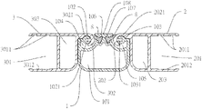
FIG. 3: Combined section view of the present invention.
FIG. 4: State diagram of in-service use of the present invention.
FIG. 5: Combined diagram of partial enlargement of FIG. 4.
FIG. 6: Schematic diagram (1) of actuation of the present invention.
FIG. 7: Schematic diagram (2) of actuation of the present invention.
FIG. 8: Three-dimensional exploded view of another embodiment of the present invention.
FIG. 9: Three-dimensional combined diagram of another embodiment of the present invention.
FIG. 10: Combined section view of another embodiment of the present invention.
FIG. 11: State diagram of in-service use of another embodiment of the present invention.
FIG. 12: Combined diagram of partial enlargement of FIG. 11.
FIG. 13: Schematic diagram (1) of actuation of another embodiment of the present invention.
FIG. 14: Schematic diagram (2) of actuation of another embodiment of the present invention.
EMBODIMENTS
To further clarify the purpose, effect and structural feature of the present invention, the following preferred embodiments are given and described with figures.
As shown in FIG. 1 and FIG. 3, the present invention is a hard-top loose-leaf plate structure device for the rear compartment of pickup trucks, which comprises a main aluminum extrusion strip 1, a right aluminum extrusion strip 2, a left aluminum extrusion strip 3 and a T-fixing strip 8, wherein
The main aluminum extrusion strip 1, as shown in FIG. 3, is an aluminum extrusion strip with square section, there is a slot opening 101 in the bottom of its center. A platform 108 is formed on the top surface of slot opening 101. There is a right T-slot 107 arranged slantwise on the right of platform 108, and there is a left T-slot 106 arranged slantwise on the left of platform 108. The right T-slot 107 and the left T-slot 106 are arranged symmetrically. There is a right circular arc slot 105 in the right side edge of platform 108, and there is a right circular lug 103 in the right circular arc slot 105. There is a left circular arc slot 104 in the left side edge of platform 108, and there is a left circular lug 102 in the left circular arc slot 104. The right circular arc slot 105 and the right circular lug 103 therein are symmetrical to the left circular arc slot 104 and the left circular lug 102 therein.
The right aluminum extrusion strip 2, as shown in FIG. 3, has a hook-like part 202 on left side edge, and an open-ended square fixing channel 201 is formed on the right side edge. There is a slot opening 203 between the hook-like part 202 and square fixing channel 201. The upper inner side wall of the square fixing channel 201 has a plurality of small concave channels 2011, and the lower inner side wall of the square fixing channel 201 has a large concave channel 2012.
The left aluminum extrusion strip 3, as shown in FIG. 3, has a hook-like part 302 on right side edge, and an open-ended square fixing channel 301 is formed on the left side edge. There is a slot opening 303 between the hook-like part 302 and square fixing channel 301. The upper inner side wall of the square fixing channel 301 has a plurality of small concave channels 3011, and the lower inner side wall of the square fixing channel 301 has a large concave channel 3012.
The T-fixing strip 8, as shown in FIG. 3, is a columnar fixing strip with T-shaped section, the bottom of the other bolt of the head of T shape is oblique.
The assembly is shown in FIG. 1, FIG. 2 and FIG. 3, the right aluminum extrusion strip 2 of the present invention is mounted in the right circular arc slot 105 of main aluminum extrusion strip 1, the hook-like part 202 of right aluminum extrusion strip 2 is fixed to the right circular lug 103 of main aluminum extrusion strip 1, even if the circular arc slot 2021 of the hook-like part 202 wraps the right circular lug 103, the right aluminum extrusion strip 2 can rotate on the right circular lug 103 of main aluminum extrusion strip 1 using the hook-like part 202. Afterwards, the left aluminum extrusion strip 3 of the present invention is mounted in the left circular arc slot 104 of main aluminum extrusion strip 1, the hook-like part 302 of left aluminum extrusion strip 3 is fixed to the left circular lug 102 of main aluminum extrusion strip 1. Even if the circular arc slot 3021 of the hook-like part 302 wraps the left circular lug 102, the left aluminum extrusion strip 2 can rotate on the left circular lug 102 of main aluminum extrusion strip 1 using the hook-like part 302. Finally, the T-fixing strip 8 is put in the right T-slot 107 and left T-slot 106 of main aluminum extrusion strip 1 respectively, the assembly of loose-leaf structure device of the present invention is completed.
Please refer to FIG. 1, FIG. 2 and FIG. 4, the assembled loose-leaf structure devices of the present invention are assembled by using a plurality of main fixing blocks 4, left fixing block 5, right fixing block 6, aluminum extrusion strip 7 and long plate 13. The main fixing block 4 is inserted in the slot opening 101 of main aluminum extrusion body 1, the left fixing block 5 is inserted in the slot opening 303 of left aluminum extrusion strip 3, the right fixing block 6 is inserted in the slot opening 203 of right aluminum extrusion strip 2. The aluminum extrusion strip 7 is integrated with left fixing block 5 and right fixing block 6 respectively (as shown in FIG. 2). Afterwards, a plurality of long plates 13 and aluminum extrusion strip 7 are assembled in line, as well as a plurality of assembled loose-leaf structure devices of the present invention, the integral structure of hard-top loose-leaf plate 9 shown in FIG. 4 and FIG. 5 is completed. As long as the integral hard-top loose-leaf plate 9 is installed on the rear compartment of pickup truck, the rear compartment of the pickup truck is provided with a closed hard-top cover structure.
The operation is shown in FIG. 3, FIG. 5 and FIG. 6. To open the hard-top loose-leaf plate 9 installed on the rear compartment of pickup truck as shown in FIG. 4 for taking something, it is free to open a single long plate 13 on any side according to the user requirement. Which is to say, to open the long plate 13 on the let aluminum extrusion strip 3, as long as the long plate 13 fixed to the left aluminum extrusion strip 3 is pulled, the hook-like part 302 of the left aluminum extrusion strip 3 will revolve on the left circular lug 102 of main aluminum extrusion strip 1, so that the left aluminum extrusion strip 3 is opened at 90° (as shown in FIG. 6). When the opening angle is 90°, the left aluminum extrusion strip 3 is immobilized by the T-fixing strip 8. On the contrary, to open the long plate 13 on the right aluminum extrusion strip 2, as long as the long plate 13 fixed to the right aluminum extrusion strip 2 is pulled, the hook-like part 202 of the right aluminum extrusion strip 2 will revolve on the right circular lug 103 of main aluminum extrusion strip 1, so that the right aluminum extrusion strip 2 is opened at 90° (as shown in FIG. 7). When the opening angle is 90°, the right aluminum extrusion strip 2 is immobilized by the T-fixing strip 8. To lay the left aluminum extrusion strip 3 and right aluminum extrusion strip 2 flat at 180°, as long as the long plate 13 is pressed, the flat state of hard-top loose-leaf plate shown in FIG. 4 can be restored easily.
FIGS. 8 to 10 show another specific embodiment of the present invention, the main difference is that the section of the long main aluminum extrusion strip 10 is strip shaped, it comprises a long main aluminum extrusion strip 10, a right aluminum extrusion strip 2, a left aluminum extrusion strip 3 and a T-fixing strip 8, wherein
The long main aluminum extrusion strip 10, as shown in FIG. 10, is an aluminum extrusion strip with an elongated quadrangular section, there is a slot opening 1001 in the bottom of its center. A platform 1008 is formed on the top surface of slot opening 1001. There is a right T-slot 1007 arranged slantwise on the right of platform 1080, and there is a left T-slot 1006 arranged slantwise on the left of platform 1008. The right T-slot 1007 and the left T-slot 1006 are arranged symmetrically. There is a right circular arc slot 1005 in the right side edge of platform 1008, and there is a right circular lug 1003 in the right circular arc slot 1005. There is a left circular arc slot 1004 in the left side edge of platform 1008, and there is a left circular lug 1002 in the left circular arc slot 1004. The right circular arc slot 1005 and the right circular lug 1003 therein are symmetrical to the left circular arc slot 1004 and the left circular lug 1002 therein.
The assembly is shown in FIG. 8, FIG. 9 and FIG. 10. The right aluminum extrusion strip 2 of the present invention is mounted in the right circular arc slot 1005 of long main aluminum extrusion strip 10, the hook-like part 202 of right aluminum extrusion strip 2 is fixed to the right circular lug 1003 of long main aluminum extrusion strip 10, even if the circular arc slot 2021 of the hook-like part 202 wraps the right circular lug 1003, the right aluminum extrusion strip 2 can rotate on the right circular lug 1003 of long main aluminum extrusion strip 10 using the hook-like part 202. Afterwards, the left aluminum extrusion strip 3 of the present invention is mounted in the left circular arc slot 1004 of long main aluminum extrusion strip 10, the hook-like part 302 of left aluminum extrusion strip 3 is fixed to the left circular lug 1002 of long main aluminum extrusion strip 10, even if the circular arc slot 3021 of the hook-like part 302 wraps the left circular lug 1002, the left aluminum extrusion strip 2 can rotate on the left circular lug 1002 of long main aluminum extrusion strip 10 using the hook-like part 302. Finally, the T-fixing strip 8 is put in the right T-slot 1007 and left T-slot 1006 of long main aluminum extrusion strip 10 respectively, the assembly of loose-leaf structure device of another embodiment of the present invention is completed.
Please refer to FIG. 8, FIG. 9 and FIG. 11, the assembled loose-leaf structure devices of the present invention in another embodiment are assembled by using a plurality of long main fixing blocks 11, left fixing block 5, right fixing block 6, aluminum extrusion strip 7 and long plate 13. The long main fixing block 411 is inserted in the slot opening 1001 of long main aluminum extrusion body 10, the left fixing block 5 is inserted in the slot opening 303 of left aluminum extrusion strip 3, the right fixing block 6 is inserted in the slot opening 203 of right aluminum extrusion strip 2. The aluminum extrusion strip 7 is integrated with left fixing block 5 and right fixing block 6 respectively (as shown in FIG. 9). Afterwards, a plurality of long plates 13 and aluminum extrusion strip 7 are assembled in line, as well as a plurality of assembled loose-leaf structure devices of the present invention in another embodiment, the integral structure of hard-top loose-leaf plate 12 shown in FIG. 1I and FIG. 12 is completed. As long as the integral hard-top loose-leaf plate 12 is installed on the rear compartment of pickup truck, the rear compartment of the pickup truck is provided with a closed hard-top cover structure.
The operation is shown in FIG. 10, FIG. 12 and FIG. 13. To open the hard-top loose-leaf plate 12 installed on the rear compartment of pickup truck shown in FIG. 11 to take something, it is free to open a single long plate 13 on any side according to the user requirement. Which is to say, to open the long plate 13 on the left aluminum extrusion strip 3, as long as the long plate 13 fixed to the left aluminum extrusion strip 3 is pulled, the hook-like part 302 of the left aluminum extrusion strip 3 will revolve on the left circular lug 1002 of long main aluminum extrusion strip 10, so that the left aluminum extrusion strip 3 is opened at 90° (as shown in FIG. 13). When the opening angle is 90°, the left aluminum extrusion strip 3 is immobilized by the T-fixing strip 8. On the contrary, to open the long plate 13 on the right aluminum extrusion strip 2, as long as the long plate 13 fixed to the right aluminum extrusion strip 2 is pulled, the hook-like part 202 of the right aluminum extrusion strip 2 will revolve on the right circular lug 1003 of long main aluminum extrusion strip 10, so that the right aluminum extrusion strip 2 is opened at 90° (as shown in FIG. 14). When the opening angle is 90°, the right aluminum extrusion strip 2 is immobilized by the T-fixing strip 8. To place the left aluminum extrusion strip 3 and right aluminum extrusion strip 2 flat at 180°, as long as the long plate 13 is pressed, the flat state of hard-top loose-leaf plate shown in FIG. 4 can be restored easily.
To sum up, the hard-top loose-leaf plate structure device for the rear compartment of pickup trucks of the present invention is designed by the inventor of the present inventor with meticulous care, it has a particular, simple and easily opened structure, and it is characterized by innovation thinking and simplified assembly, meeting the essentials of patent for invention of Patent Act. Therefore, an application is filed according to law, looking forward to the reviewers' approval, thank you.
Although the invention has been explained in relation to its preferred embodiment, it is to be understood that many other possible modifications and variations can be made without departing from the spirit and scope of the invention as hereinafter claimed.
SYMBOL DESCRIPTION
  • 1 . . . Main aluminum extrusion strip 101 . . . Slot opening
  • 102 . . . Left circular lug 1021 . . . U-shaped channel
  • 103 . . . Right circular lug 1031 . . . U-shaped channel
  • 104 . . . Left circular arc slot 105 . . . Right circular arc slot
  • 106 . . . Left T-slot 107 . . . Right T-slot
  • 108 . . . Platform
  • 2 . . . Right aluminum extrusion strip 201 . . . Square fixing channel
  • 2011 . . . Small concave channel 2012 . . . Large concave channel
  • 202 . . . Hook-like part 2021 . . . Circular arc slot
  • 203 . . . Slot opening
  • 3 . . . Right aluminum extrusion strip 301 . . . Square fixing channel
  • 3011 . . . Small concave channel 3012 . . . Large concave channel
  • 302 . . . Hook-like part 3021 . . . Circular arc slot
  • 303 . . . Slot opening
  • 4 . . . Main fixing block 5 . . . Left fixing block
  • 6 . . . Right fixing block 7 . . . Aluminum extrusion strip
  • 8 . . . T-fixing strip 9 . . . Hard-top loose-leaf plate
  • 10 . . . Long main aluminum extrusion strip 1001 . . . Slot opening
  • 1002 . . . Left circular lug 1003 . . . Right circular lug
  • 1004 . . . Left circular arc slot 1005 . . . Right circular arc slot
  • 1006 . . . Left T-slot 1007 . . . Right T-slot
  • 1008 . . . Platform
  • 11 . . . Long main fixing block 12 . . . Hard-top loose-leaf plate
  • 13 . . . Long plate

Claims (2)

What is claimed is:
1. A hard-top loose-leaf plate structure device for a rear compartment of a pickup truck, comprising:
a main aluminum extrusion strip, a right aluminum extrusion strip, a left aluminum extrusion strip and a T-fixing strip,
wherein the main aluminum extrusion strip is an aluminum extrusion strip with a square section, wherein a slot opening is provided in a bottom of a center of the main aluminum extrusion strip, wherein a platform is formed on a top surface of the slot opening, wherein a right T-slot is arranged slantwise on a right side of the platform, wherein a left T-slot is arranged slantwise on a left of the platform, wherein the right T-slot and the left T-slot are arranged symmetrically,
wherein a right circular arc slot is provided in a right side edge of the platform, wherein a right circular lug is provided in the right circular arc slot, wherein a left circular arc slot is provided in a left side edge of the platform, wherein a left circular lug is provided in the left circular arc slot, wherein the right circular arc slot and the right circular lug therein are symmetrical to the left circular arc slot and the left circular lug therein;
wherein the right aluminum extrusion strip has a right hook-like part on a left side edge of the right aluminum extrusion strip, wherein a right open-ended square fixing channel is formed on a right side edge of the right aluminum extrusion strip, wherein a right slot opening is provided between the right hook-like part and the right open-ended square fixing channel, wherein an upper inner side wall of the right open-ended square fixing channel has a right plurality of small concave channels, wherein a lower inner side wall of the right open-ended square fixing channel has a right concave channel;
wherein the left aluminum extrusion strip has a left hook-like part on a right side edge of the left aluminum extrusion strip, wherein a left open-ended square fixing channel is formed on a left side edge of the left aluminum extrusion strip, wherein a left slot opening is provided between the left hook-like part and the left open-ended square fixing channel, wherein an upper inner side wall of the left open-ended square fixing channel has a left plurality of small concave channels, wherein a lower inner side wall of the left open-ended square fixing channel has a left large concave channel;
wherein the T-fixing strip is a columnar fixing strip with a T-shaped section, wherein a bottom of a bolt of a head of the T shape is oblique.
2. The hard-top loose-leaf plate structure device of claim 1,
wherein a section of the main aluminum extrusion strip is an elongated quadrangle, forming a structure of a long main aluminum extrusion strip.
US17/134,119 2020-12-24 2020-12-24 Hard-top loose-leaf plate structure device for rear compartment of pickup trucks Active US11407294B2 (en)

Priority Applications (1)

Application Number Priority Date Filing Date Title
US17/134,119 US11407294B2 (en) 2020-12-24 2020-12-24 Hard-top loose-leaf plate structure device for rear compartment of pickup trucks

Applications Claiming Priority (1)

Application Number Priority Date Filing Date Title
US17/134,119 US11407294B2 (en) 2020-12-24 2020-12-24 Hard-top loose-leaf plate structure device for rear compartment of pickup trucks

Publications (2)

Publication Number Publication Date
US20220203810A1 US20220203810A1 (en) 2022-06-30
US11407294B2 true US11407294B2 (en) 2022-08-09

Family

ID=82118434

Family Applications (1)

Application Number Title Priority Date Filing Date
US17/134,119 Active US11407294B2 (en) 2020-12-24 2020-12-24 Hard-top loose-leaf plate structure device for rear compartment of pickup trucks

Country Status (1)

Country Link
US (1) US11407294B2 (en)

Cited By (5)

* Cited by examiner, † Cited by third party
Publication number Priority date Publication date Assignee Title
US12011982B1 (en) * 2023-09-28 2024-06-18 Shenzhen WKSP Power Technology Co., Ltd. Foldable cover plate
US20240286471A1 (en) * 2023-02-23 2024-08-29 Tony Waygong Chiu Hard folding car cover
US20240286470A1 (en) * 2023-02-23 2024-08-29 Tony Waygong Chiu Folding car cover with support bar
US20250388068A1 (en) * 2023-02-17 2025-12-25 Zhejiang Surpass Auto Parts Co.,Ltd. Car cover with special clamping handles
US12522059B2 (en) * 2023-02-27 2026-01-13 Zhejiang Surpass Auto Parts Co., Ltd. Embedded car cover

Citations (7)

* Cited by examiner, † Cited by third party
Publication number Priority date Publication date Assignee Title
US20080100088A1 (en) * 2006-10-26 2008-05-01 Extang Corporation Solid fold tonneau system
US9039066B1 (en) * 2013-12-17 2015-05-26 Cyc Engineering, Inc. Foldable tonneau cover for pick-up truck and waterproof flexible strip thereof
US20160200376A1 (en) * 2015-01-08 2016-07-14 Toyota Motor Engineering & Manufacturing North America, Inc. Molded tonneau cover apparatus
US20160340949A1 (en) * 2015-05-22 2016-11-24 Cixi City Liyuan Auto Parts Co., Ltd Hard cover
CN107719085A (en) * 2017-11-16 2018-02-23 佛山市锐创汽车用品有限公司 A kind of pivot structure and boot flype
US10471814B1 (en) * 2019-05-28 2019-11-12 Ningbo Diroan Auto Accessories Co., Ltd. Turnover assembly of pickup truck carriage cover
US20210291633A1 (en) * 2020-03-23 2021-09-23 Ningbo Kuatu Electronic Tech. Co. Ltd. Steady bed cover of pickup truck

Patent Citations (7)

* Cited by examiner, † Cited by third party
Publication number Priority date Publication date Assignee Title
US20080100088A1 (en) * 2006-10-26 2008-05-01 Extang Corporation Solid fold tonneau system
US9039066B1 (en) * 2013-12-17 2015-05-26 Cyc Engineering, Inc. Foldable tonneau cover for pick-up truck and waterproof flexible strip thereof
US20160200376A1 (en) * 2015-01-08 2016-07-14 Toyota Motor Engineering & Manufacturing North America, Inc. Molded tonneau cover apparatus
US20160340949A1 (en) * 2015-05-22 2016-11-24 Cixi City Liyuan Auto Parts Co., Ltd Hard cover
CN107719085A (en) * 2017-11-16 2018-02-23 佛山市锐创汽车用品有限公司 A kind of pivot structure and boot flype
US10471814B1 (en) * 2019-05-28 2019-11-12 Ningbo Diroan Auto Accessories Co., Ltd. Turnover assembly of pickup truck carriage cover
US20210291633A1 (en) * 2020-03-23 2021-09-23 Ningbo Kuatu Electronic Tech. Co. Ltd. Steady bed cover of pickup truck

Cited By (7)

* Cited by examiner, † Cited by third party
Publication number Priority date Publication date Assignee Title
US20250388068A1 (en) * 2023-02-17 2025-12-25 Zhejiang Surpass Auto Parts Co.,Ltd. Car cover with special clamping handles
US20240286471A1 (en) * 2023-02-23 2024-08-29 Tony Waygong Chiu Hard folding car cover
US20240286470A1 (en) * 2023-02-23 2024-08-29 Tony Waygong Chiu Folding car cover with support bar
US20250276567A1 (en) * 2023-02-23 2025-09-04 Tony Waygong Chiu Hard folding car cover
US12502940B2 (en) * 2023-02-23 2025-12-23 Tony Waygong Chiu Folding car cover with support bar
US12522059B2 (en) * 2023-02-27 2026-01-13 Zhejiang Surpass Auto Parts Co., Ltd. Embedded car cover
US12011982B1 (en) * 2023-09-28 2024-06-18 Shenzhen WKSP Power Technology Co., Ltd. Foldable cover plate

Also Published As

Publication number Publication date
US20220203810A1 (en) 2022-06-30

Similar Documents

Publication Publication Date Title
US11407294B2 (en) Hard-top loose-leaf plate structure device for rear compartment of pickup trucks
US9376147B2 (en) Two-stage cargo floor
US9815358B1 (en) Foldable tonneau cover with an extruded forward section
US11993138B2 (en) Buckle locking structure device for rear compartment cover of pickup trucks
JP2006513089A (en) Vehicle luggage management device having a movable luggage support arm
US7066516B2 (en) Rear vehicle storage system
JP2016041554A (en) Car luggage compartment structure
US20160236729A1 (en) Trailer Overhang Storage
JP4992390B2 (en) Storage structure for vehicles
US20140097221A1 (en) Car roof storage compartment with a closed-end zipper
CN205871848U (en) Compartment cover and bonnet lock behind pick up car
JP2016008009A (en) Vehicle storage structure
JP2014108701A (en) Article storage case for vehicle
GB2436816A (en) A vehicle with a covered load recess
KR20220014783A (en) auxiliary loading dock for cargo vehicles
US20140305980A1 (en) Vehicle accessory retaining system
CN207747830U (en) A kind of automobile armrest case lid and automobile handrail box
CN119305488A (en) Cab space expansion device and truck
CN105501129A (en) Multi-functional storage box used for automobile trunk
CN116394844A (en) Automobile storage structure and vehicle
JP4202341B2 (en) Tire lid structure
JPS63119413U (en)
CN101898533B (en) Outer reflector device for vehicle
TWD242266S (en) roof box
US20140103055A1 (en) Removable two panel closure

Legal Events

Date Code Title Description
FEPP Fee payment procedure

Free format text: ENTITY STATUS SET TO UNDISCOUNTED (ORIGINAL EVENT CODE: BIG.); ENTITY STATUS OF PATENT OWNER: MICROENTITY

FEPP Fee payment procedure

Free format text: ENTITY STATUS SET TO SMALL (ORIGINAL EVENT CODE: SMAL); ENTITY STATUS OF PATENT OWNER: MICROENTITY

Free format text: ENTITY STATUS SET TO MICRO (ORIGINAL EVENT CODE: MICR); ENTITY STATUS OF PATENT OWNER: MICROENTITY

STCF Information on status: patent grant

Free format text: PATENTED CASE