US11407056B2 - Pierce metal for joining different materials and method of joining different materials using pierce metal - Google Patents
Pierce metal for joining different materials and method of joining different materials using pierce metal Download PDFInfo
- Publication number
- US11407056B2 US11407056B2 US16/837,321 US202016837321A US11407056B2 US 11407056 B2 US11407056 B2 US 11407056B2 US 202016837321 A US202016837321 A US 202016837321A US 11407056 B2 US11407056 B2 US 11407056B2
- Authority
- US
- United States
- Prior art keywords
- shaft
- aluminum die
- iron
- head
- cast member
- Prior art date
- Legal status (The legal status is an assumption and is not a legal conclusion. Google has not performed a legal analysis and makes no representation as to the accuracy of the status listed.)
- Active, expires
Links
Images


Classifications
-
- B—PERFORMING OPERATIONS; TRANSPORTING
- B23—MACHINE TOOLS; METAL-WORKING NOT OTHERWISE PROVIDED FOR
- B23K—SOLDERING OR UNSOLDERING; WELDING; CLADDING OR PLATING BY SOLDERING OR WELDING; CUTTING BY APPLYING HEAT LOCALLY, e.g. FLAME CUTTING; WORKING BY LASER BEAM
- B23K11/00—Resistance welding; Severing by resistance heating
- B23K11/002—Resistance welding; Severing by resistance heating specially adapted for particular articles or work
- B23K11/004—Welding of a small piece to a great or broad piece
- B23K11/0066—Riveting
-
- B—PERFORMING OPERATIONS; TRANSPORTING
- B23—MACHINE TOOLS; METAL-WORKING NOT OTHERWISE PROVIDED FOR
- B23K—SOLDERING OR UNSOLDERING; WELDING; CLADDING OR PLATING BY SOLDERING OR WELDING; CUTTING BY APPLYING HEAT LOCALLY, e.g. FLAME CUTTING; WORKING BY LASER BEAM
- B23K11/00—Resistance welding; Severing by resistance heating
- B23K11/10—Spot welding; Stitch welding
- B23K11/11—Spot welding
- B23K11/115—Spot welding by means of two electrodes placed opposite one another on both sides of the welded parts
-
- B—PERFORMING OPERATIONS; TRANSPORTING
- B23—MACHINE TOOLS; METAL-WORKING NOT OTHERWISE PROVIDED FOR
- B23K—SOLDERING OR UNSOLDERING; WELDING; CLADDING OR PLATING BY SOLDERING OR WELDING; CUTTING BY APPLYING HEAT LOCALLY, e.g. FLAME CUTTING; WORKING BY LASER BEAM
- B23K2103/00—Materials to be soldered, welded or cut
- B23K2103/18—Dissimilar materials
- B23K2103/20—Ferrous alloys and aluminium or alloys thereof
Definitions
- the technology relates to a pierce metal for joining different materials and a method of joining the different materials using the pierce metal.
- the technology relates to a pierce metal used for joining different materials including an aluminum die-cast member and an iron-based member, and a method of joining the different materials using the pierce metal.
- a pierce metal for joining different materials (hereinafter may be simply referred to as a “pierce metal”) disclosed in Japanese Patent No. 5722479 can be used.
- a pierce metal for joining different materials (hereinafter may be simply referred to as a “pierce metal”) disclosed in Japanese Patent No. 5722479 can be used.
- Such a method joins the aluminum alloy member and the iron-based member together by driving the pierce metal into the aluminum alloy member to fix them together and performing spot welding of the pierce metal and the iron-based member.
- the pierce metal includes a head and a shaft protruded from the head.
- the head and the shaft are formed integrally by an iron-based material. Causing the shaft to penetrate the aluminum alloy member from a tip surface of the protrusion of the shaft allows the pierce metal to be swaged and thus fixed to the aluminum alloy member owing to a swaging part provided on the head. This also allows an outer peripheral surface of the shaft to come into contact with the aluminum alloy member. Thereafter, the iron-based member is brought into contact with the penetrating tip surface of the shaft, following which the iron-based member and the head of the pierce metal are held under pressure by a pair of weld electrodes and are applied with electric power by the weld electrodes. Thus, the tip of the shaft is spot-welded to the iron-based member, allowing the aluminum alloy member and the iron-based member to be joined together.
- An aspect of the technology provides a pierce metal for joining different materials including an aluminum die-cast member and an iron-based member.
- the pierce metal includes a head and a shaft.
- the shaft is provided integrally with the head and protrudes from the head, and includes an outer peripheral surface and a protruded tip surface.
- the shaft is configured to penetrate through the aluminum die-cast member with the protruded tip surface being exposed from the aluminum die-cast member, and the outer peripheral surface is configured to come into contact with a through-hole of the aluminum die-cast member, upon joining the aluminum die-cast member and the iron-based member together.
- the head and the iron-based member which is in contact with the protruded tip surface are configured to be held under pressure by a pair of weld electrodes and are configured to be applied with electric power by the pair of weld electrodes to perform spot welding of the protruded tip surface and the iron-based member, upon joining the aluminum die-cast member and the iron-based member together.
- the outer peripheral surface includes a non-contact part configured to come into non-contact with the through-hole in a state in which the shaft is penetrated through the aluminum die-cast member.
- An aspect of the technology provides a pierce metal for joining different materials including an aluminum die-cast member and an iron-based member.
- the pierce metal includes a head, a shaft, and a hollow part.
- the shaft is provided integrally with the head and protrudes from the head, and includes an outer peripheral surface and a protruded tip surface.
- the hollow part extends from the head to the shaft, excluding the protruded tip surface.
- the shaft is configured to penetrate through the aluminum die-cast member with the protruded tip surface being exposed from the aluminum die-cast member, and the outer peripheral surface is configured to come into contact with a through-hole of the aluminum die-cast member, upon joining the aluminum die-cast member and the iron-based member together.
- the head and the iron-based member which is in contact with the protruded tip surface are configured to be held under pressure by a pair of weld electrodes and are configured to be applied with electric power by the pair of weld electrodes to perform spot welding of the protruded tip surface and the iron-based member, upon joining the aluminum die-cast member and the iron-based member together.
- An aspect of the technology provides a method of joining different materials including an aluminum die-cast member and an iron-based member.
- the method includes preparing a pierce metal for joining the different materials.
- the pierce metal includes a head and a shaft that is provided integrally with the head and protrudes from the head, and the shaft includes an outer peripheral surface and a protruded tip surface.
- the method includes driving the pierce metal into the aluminum die-cast member to cause the shaft to penetrate through the aluminum die-cast member with the protruded tip surface being exposed from the aluminum die-cast member in such a manner that the outer peripheral surface comes into contact with a through-hole of the aluminum die-cast member, and the outer peripheral surface includes a non-contact part that comes into non-contact with the through-hole in a state in which the shaft is penetrated through the aluminum die-cast member.
- the method includes spot welding the protruded tip surface and the iron-based member, through holding the head and the iron-based member which is in contact with the protruded tip surface under pressure by a pair of weld electrodes and applying electric power to the head and the iron-based member by the pair of weld electrodes.
- An aspect of the technology provides a method of joining different materials including an aluminum die-cast member and an iron-based member.
- the method includes preparing a pierce metal for joining the different materials.
- the pierce metal includes a head, a shaft that is provided integrally with the head and protrudes from the head, and includes an outer peripheral surface and a protruded tip surface, and a hollow part extending from the head to the shaft, excluding the protruded tip surface.
- the method includes driving the pierce metal into the aluminum die-cast member to cause the shaft to penetrate through the aluminum die-cast member with the protruded tip surface being exposed from the aluminum die-cast member in such a manner that the outer peripheral surface comes into contact with a through-hole of the aluminum die-cast member.
- the method includes spot welding the protruded tip surface and the iron-based member, through holding the head and the iron-based member which is in contact with the protruded tip surface under pressure by a pair of weld electrodes and applying electric power to the head and the iron-based member by the pair of weld electrodes.
- FIGS. 1A and 1B are cross-sectional views, before spot welding, of a pierce metal for joining different material according to one example embodiment of the technology, which is used for a method of joining the different materials according to one example embodiment of the technology, in which FIG. 1A is a cross-sectional view of the pierce metal having a recess, and FIG. 1B is a cross-sectional view of the pierce metal without the recess.
- FIG. 2 is a cross-sectional view of the pierce metal illustrated in FIGS. 1A and 1B , according to a first modification example.
- FIG. 3 is a cross-sectional view of the pierce metal illustrated in FIGS. 1A and 1B , according to a second modification example.
- FIG. 4 is a cross-sectional view of the pierce metal illustrated in FIGS. 1A and 1B , according to a third modification example.
- FIG. 5 is a cross-sectional view of the pierce metal illustrated in FIGS. 1A and 1B , according to a fourth modification example.
- FIG. 6 is an explanatory diagram illustrating a crack generated on an aluminum die-cast member.
- FIG. 7A is a schematic cross-sectional view of the pierce metal in which an electrode is misaligned in a horizontal direction in the drawing from the middle of a head of the pierce metal with which the electrode should come into contact.
- FIG. 7B is an explanatory diagram illustrating current densities upon application of electric power in the pierce metal illustrated in any of FIGS. 1A to 5 .
- FIGS. 8A and 8B are each an explanatory diagram illustrating a spot weld electrode brought into contact with a head of the pierce metal illustrated in any of FIGS. 1A to 5 .
- an aluminum alloy member especially an aluminum die-cast member in which an aluminum alloy is casted, and an iron-based member are joined together by spot welding that uses a pierce metal for joining different materials (hereinafter may be simply referred to as a “pierce metal”)
- a crack or a break can occur on the aluminum die-cast member.
- the occurrence of the crack or the break is prominent in the vicinity of an edge of the aluminum die-cast member.
- the aluminum die-cast member may be thermally treated to increase the ductility, prior to the joining of the aluminum die-cast member and the iron-based member by the pierce metal.
- a pierce metal that reduces or prevents the occurrence of the crack of the aluminum die-cast member even upon joining different materials including the aluminum die-cast member and the iron-based member by means of the spot welding, and a method of joining the different materials using the pierce metal.
- spot welding in which electrodes are mounted on a manipulator such as an industrial robot has been widely performed upon spot-welding a panel member for a vehicle.
- the panel member to be subjected to such spot welding is large in size, which can cause misalignment, to some extent, of positions at which the respective electrodes come into contact with the panel member. If the electrode is misaligned from the middle of a head of the pierce metal, a branch current is generated in the aluminum die-cast member, which is higher in electric conductivity than the iron-based member configuring the pierce metal.
- the generation of the branch current can cause melting and its consequential scattering of the aluminum die-cast member or can lead to a decrease in nugget diameter, which in turn can result in insufficient joining of the pierce metal and the iron-based member.
- the pierce metal that helps to ensure the joining of the aluminum die-cast member and the iron-based member through the pierce metal even upon joining different materials including the aluminum die-cast member and the iron-based member by means of the spot welding, and a method of joining the different materials using the pierce metal.
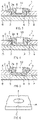
- FIGS. 1A and 1B are cross-sectional views, before spot welding, of a pierce metal for joining different materials (hereinafter may be simply referred to as a “pierce metal”) 1 according to an example embodiment.
- FIGS. 1A and 1B illustrate a state in which a shaft 3 of the pierce metal 1 is penetrated through an aluminum die-cast plate A and an iron-based plate B is brought into contact with a penetrating tip surface 4 of the shaft 3 .
- the aluminum die-cast plate A may serve as an “aluminum die-cast member”.
- the iron-based plate B may serve as an “iron-based member”.
- a head 2 of the pierce metal 1 and the iron-based plate B are held under pressure by a pair of electrodes E and are applied with a spot-welding current between the electrodes E in the state in which the head 2 and the iron-based plate B are held under pressure by the electrodes E, as illustrated in FIG. 7A , for example.
- the shaft 3 of the pierce metal 1 may be driven into or riveted to the aluminum die-cast plate A by means of a pair of dies (e.g., a punch and a die), as disclosed in Japanese Patent No. 5722479, for example.
- a pair of dies e.g., a punch and a die
- the shaft 3 may punch through the aluminum die-cast plate A, forming a through-hole 9 on the aluminum die-cast plate A.
- the pierce metal 1 has the head 2 and the shaft 3 that are integrally formed with each other as disclosed in Japanese Patent No. 5722479, for example.
- the head 2 and the shaft 3 may include the same iron-based material.
- the head 2 may have a substantially disk shape.
- the shaft 3 is protruded from the head 2 , and may have a substantially cylindrical shape.
- the head 2 may have an outer diameter that is larger than an outer diameter of the shaft 3 .
- the head 2 and the shaft 3 may be typically coaxial with respect to each other.
- the head 2 may have a top surface 2 a , i.e., an upper surface in FIGS. 1A and 1B , that is disposed on the opposite side of the shaft 3 .
- the top surface 2 a may have a dome shape that protrudes spherically, in order to bring a location with which the electrode comes into contact upon the spot welding toward the middle.
- the head 2 may also have a surface that is positioned on the shaft 3 side, i.e., a lower surface in FIGS. 1A and 1B , and whose periphery serves as a swaging part 5 .
- the swaging part 5 may be continuously protruded in a ring shape having a semicircular cross-section.
- the surface on the shaft 3 side of the head 2 i.e., the lower surface in FIGS.
- the shaft 3 of the pierce metal 1 is driven into a member to be subjected to riveting, i.e., driven into the aluminum die-cast plate A in an example embodiment.
- the swaging part 5 as a ring-shaped projection digs into the aluminum die-cast plate A, causing a material of the aluminum die-cast plate A positioned on the inner side of the swaging part 5 to plastically flow into the recessed groove 6 and thereby allowing the pierce metal 1 to be swaged and thus fixed to the aluminum die-cast plate A.
- a curvature radius of the semicircular cross-section of the swaging part 5 may be adjusted to prevent an occurrence of a crack on the aluminum die-cast plate A upon driving the swaging part 5 into the aluminum die-cast plate A.
- the tip surface 4 of the shaft 3 may have a dome shape that protrudes spherically.
- the dome-shaped tip surface 4 may protrude from the aluminum die-cast plate A toward the iron-based plate B.
- the dimensions of the protrusion of the dome-shaped tip surface 4 from the aluminum die-cast plate A may be set in advance. For example, an angle between the dome-shaped tip surface 4 of the shaft 3 and an outer periphery of the shaft 3 influences shearing force generated when the shaft 3 punches through the aluminum die-cast plate A, and the angle varies depending on the curvature radius of a spherical surface of the tip surface 4 forming the dome shape.
- the angle depends on an outer diameter of the shaft 3 as well. If the curvature radius of the dome-shaped spherical surface of the tip surface 4 is large, the shearing force generated when the shaft 3 punches through the aluminum die-cast plate A can decrease, whereas burr can occur around the through-hole 9 following the punching if the curvature radius of the dome-shaped spherical surface of the tip surface 4 is small. In an example embodiment, to achieve a balance between these trade-off factors, the curvature radius of the dome-shaped spherical surface of the tip surface 4 may be adjusted.
- forming the tip surface 4 of the shaft 3 into the dome shape has an effect of causing a current density upon the spot welding to be concentrated at the center of the tip surface 4 of the shaft 3 and thereby helping to ensure that the nugget is formed between the center of the tip surface 4 of the shaft 3 and the iron-based plate B.
- an outer peripheral surface of the shaft 3 of the pierce metal 1 has a contact part 7 and a non-contact part 8 that are provided in a predetermined region in a direction of the protrusion of the shaft 3 .
- the contact part 7 may come into contact with an inner peripheral surface of the aluminum die-cast plate A in a state in which the shaft 3 of the pierce metal 1 is penetrated through or driven into the aluminum die-cast plate A.
- the non-contact part 8 may have a diameter smaller than a diameter of the contact part 7 , and does not come into contact with the inner peripheral surface of the aluminum die-cast plate A in the state in which the shaft 3 of the pierce metal 1 is penetrated through or driven into the aluminum die-cast plate A.
- the cross-sectional area, perpendicular to an extending direction of the shaft 3 , of the non-contact part 8 may be smaller than the cross-sectional area, perpendicular to the extending direction of the shaft 3 , of the through-hole 9 .
- the shaft 3 may have a first cylindrical contact part 7 , a second cylindrical contact part 7 , and a recessed non-contact part 8 .
- the first cylindrical contact part 7 may be provided on the head 2 side of the shaft 3 , i.e., on the base end side of the shaft 3 .
- the second cylindrical contact part 7 may be provided on the opposite side of the head 2 of the shaft 3 , i.e., on the tip of the protrusion of the shaft 3 .
- the first cylindrical contact part 7 and the second cylindrical contact part 7 each may have a diameter same as or substantially the same as a diameter of the through-hole 9 of the aluminum die-cast plate A.
- the recessed non-contact part 8 may be so recessed between the first cylindrical contact part 7 and the second cylindrical contact part 7 as to have an arc-shaped cross section.
- the first cylindrical contact part 7 that comes into contact with the through-hole 9 of the aluminum die-cast plate A helps to ensure the swaging force of the pierce metal 1 derived from the swaging part 5 and the first cylindrical contact part 7 .
- the shaft 3 has the same outer diameter as a whole, i.e., is so-called waistless, and the outer peripheral surface of the shaft 3 as a whole comes into contact with the through-hole 9 of the aluminum die-cast plate A, large stress such as compressive stress acts on the aluminum die-cast plate A due to thermal expansion upon the spot welding.
- the aluminum die-cast plate (e.g., the aluminum die-cast member) A is low in ductility as compared with a non-casted aluminum alloy, which can lead to an occurrence of a crack after the spot welding, especially a crack C that occurs on an edge of any aluminum die-casted member after the spot welding as illustrated in FIG. 6 , for example.
- the non-contact part 8 that does not come into contact with the through-hole 9 of the aluminum die-cast plate A is formed at a part of the shaft 3 , e.g., in a predetermined region in the direction of the protrusion of the shaft 3 .
- the non-contact part 8 does not come into contact with the aluminum die-cast plate A, or less presses the aluminum die-cast plate A even if the non-contact part 8 comes into contact with the aluminum die-cast plate A. Accordingly, it is possible to allow the stress to be applied to the aluminum die-cast plate A to be zero (0) or to be small and thereby to prevent the occurrence of the crack C.
- the non-contact part 8 may be provided around the entire outer periphery of the shaft 3 . In some embodiments, the non-contact part 8 may be provided only around a part of the outer periphery of the shaft 3 , which also makes it possible to achieve the effect of preventing the occurrence of the crack C.
- the technology encompasses various modifications for configurations of the contact part 7 and the non-contact part 8 .
- FIG. 2 illustrates a first modification example of the shaft 3 illustrated in FIGS. 1A and 1B .
- the shaft 3 according to the first modification example may have the cylindrical contact part 7 , an outer peripheral contact part 7 , and the recessed non-contact part 8 .
- the cylindrical contact part 7 may be provided on the head 2 side of the shaft 3 , i.e., on the base end side of the shaft 3 , and may have a diameter same as or substantially the same as the diameter of the through-hole 9 of the aluminum die-cast plate A.
- the outer peripheral contact part 7 may correspond to an outer peripheral edge of the dome-shaped tip surface 4 , and may have a diameter same as or substantially the same as the diameter of the through-hole 9 of the aluminum die-cast plate A.
- the recessed non-contact part 8 may be so recessed between the cylindrical contact part 7 and the outer peripheral contact part 7 as to have an arc-shaped cross section.
- FIG. 3 illustrates a second modification example of the shaft 3 illustrated in FIGS. 1A and 1B .
- the shaft 3 according to the second modification example may have the outer peripheral contact part 7 , an inner peripheral contact part 7 , and the recessed non-contact part 8 .
- the outer peripheral contact part 7 may correspond to the outer peripheral edge of the dome-shaped tip surface 4 .
- the inner peripheral contact part 7 may correspond only to an inner peripheral edge of the recessed groove 6 , and may have a diameter same as or substantially the same as the diameter of the through-hole 9 of the aluminum die-cast plate A.
- the recessed non-contact part 8 may be so recessed between the outer peripheral contact part 7 and the inner peripheral contact part 7 as to have an arc-shaped cross section.
- FIG. 4 illustrates a third modification example of the shaft 3 illustrated in FIGS. 1A and 1B .
- the shaft 3 according to the third modification example may have the outer peripheral contact part 7 , the inner peripheral contact part 7 , and a drum-shaped non-contact part 8 .
- the outer peripheral contact part 7 may correspond to the outer peripheral edge of the dome-shaped tip surface 4 .
- the inner peripheral contact part 7 may correspond only to the inner peripheral edge of the recessed groove 6 .
- the drum-shaped non-contact part 8 may be so recessed between the outer peripheral contact part 7 and the inner peripheral contact part 7 as to have an L-shaped cross section.
- FIG. 5 illustrates a fourth modification example of the shaft 3 illustrated in FIGS. 1A and 1B .
- the shaft 3 according to the fourth modification example may have the cylindrical contact part 7 and a chamfered non-contact part 8 .
- the cylindrical contact part 7 may have a diameter same as or substantially the same as the diameter of the through-hole 9 of the aluminum die-cast plate A, at the middle of the shaft 3 in the direction of the protrusion of the shaft 3 .
- the chamfered non-contact part 8 may be so recessed as to have a chamfered shape at the tip and a base end of the shaft 3 in the direction of the protrusion of the shaft 3 . Note that the shaft 3 according to the fourth modification example illustrated in FIG.
- the through-hole 9 can involve difficulties in shearing, by means of the outer peripheral edge of the tip surface 4 , the through-hole 9 having an inner diameter necessary for the aluminum die-cast plate A.
- the through-hole 9 may be formed in advance on the aluminum die-cast plate A, following which the shaft 3 of the pierce metal 1 may be penetrated through the through-hole 9 and may be fixed by swaging.
- the pierce metal 1 may have a hollow shape from the middle of the head 2 to the center of the shaft 3 , excluding the protruded tip surface 4 of the shaft 3 , to form the recess 10 .
- the hollow shape may serve as a “hollow part”.
- the recess 10 forming the hollow shape may be a circular hole that is coaxial with the head 2 and the shaft 3 .
- the recess 10 may have a cross-sectional shape other than the cross-sectional shape that forms the circular hole.
- the electrodes E directed to the spot welding may be mounted on a manipulator of a robot such as an industrial robot (hereinafter simply referred to as a “robot”).
- the robot typically operates along a taught track precisely; however, a panel member to be subjected to such spot welding is large in size, which can cause misalignment, to some extent, of positions at which the respective electrodes E come into contact with the panel member.
- FIG. 7A is a schematic cross-sectional view of the pierce metal 1 in which the electrode E is misaligned in a horizontal direction in the drawing from the middle of the head 2 of the pierce metal 1 with which the electrode E should come into contact.
- FIG. 7A illustrates an example in which the top surface 2 a of the head 2 is flat instead of having the dome shape, and the shaft 3 is waistless.
- a position at which the electrode E comes into contact with the pierce metal 1 is misaligned from a position above the cross-section of the shaft 3 and is positioned above the aluminum die-cast plate A accordingly as illustrated in FIG.
- a branch current is generated in the aluminum die-cast plate A, which is higher in electric conductivity than an iron-based material configuring the pierce metal, if the head 2 and the shaft 3 are both solid.
- the generation of the branch current can cause melting and its consequential scattering of the aluminum die-cast plate A or can lead to a decrease in nugget diameter, which in turn can result in insufficient joining of the pierce metal 1 and the iron-based plate B.
- FIG. 7B illustrates current densities upon the spot welding at the tip surface 4 of the shaft 3 of the pierce metal 1 .
- the current densities illustrated in FIG. 7B correspond to the respective positions of the electrode E illustrated in FIG. 7A , in which a broken line denotes the current density at the tip surface 4 of the shaft 3 of the pierce metal 1 in which both the head 2 and the shaft 3 are solid.
- a broken line denotes the current density at the tip surface 4 of the shaft 3 of the pierce metal 1 in which both the head 2 and the shaft 3 are solid.
- the current density tends to become maximum at a position with which the electrode E is in contact.
- the head 2 and the shaft 3 both having the hollow shape allow the current density upon the spot welding at the tip surface 4 of the shaft 3 to be maximum at the center of the tip surface 4 of the shaft 3 , as denoted by a solid line in FIG. 7B .
- forming the head 2 and the shaft 3 into the hollow shape allows the spot-welding current to be concentrated at the center of the tip surface 4 of the shaft 3 and thereby makes it possible to increase the nugget diameter while reducing or preventing the melting of the aluminum die-cast plate A. This helps to ensure that the pierce metal 1 and the iron-based plate B are joined together.
- the recess 10 derived from the hollow shapes of the head 2 and the shaft 3 may have a shape in which a bottom of the recess 10 is located at a predetermined position.
- the predetermined position may be where a distance from the bottom of the recess 10 to the tip surface 4 of the shaft 3 is half or less than the dimensions of the protrusion of the shaft 3 .
- forming the top surface 2 a of the head 2 into the dome shape allows for further concentration of the current density upon the spot welding at the center of the tip surface 4 of the shaft 3 .
- forming the head 2 and the shaft 3 into the hollow shape also helps to reduce the occurrence of the crack upon the spot welding.
- the hollow shape allows an amount of expansion toward the outer side in a radial direction resulting from a sensible heat to be smaller than that of the solid shape. Accordingly, it is possible to reduce, by an amount corresponding to the reduced amount of the expansion, the compressive stress that acts on the aluminum die-cast plate A due to the thermal expansion of the shaft 3 upon the spot welding, and thereby to reduce the occurrence of the crack.
- the top surface 2 a of the head 2 may also be so protruded as to have the dome shape. If the top surface 2 a of the head 2 is flat as illustrated in FIG. 8B , it is difficult or not possible to bring, toward the middle of the head 2 , the position with which the electrode E comes into contact to correct the misalignment, as with an example illustrated in FIG. 7A . However, forming the top surface 2 a of the head 2 into the spherical dome shape allows the position with which the electrode E comes into contact to be brought toward the middle of the head 2 even in a case where the electrode E is positioned at the same position as a case where the top surface 2 a of the head 2 is flat, as illustrated in FIG. 8A .
- the head 2 and the shaft 3 may be made solid, owing to the spherical dome-shaped top surface 2 a of the head 2 that allows the current density upon the spot welding to be concentrated at the center of the tip surface 4 of the shaft 3 .
- the pierce metal or the method of joining the different materials using the pierce metal includes the pierce metal 1 having the shaft 3 that includes the contact part 7 and the non-contact part 8 .
- the contact part 7 may come into contact with the through-hole 9 of the aluminum die-cast plate A in a state in which the shaft 3 of the pierce metal 1 is penetrated through the aluminum die-cast plate A.
- the non-contact part 8 may have a diameter smaller than the diameter of the contact part 7 , and does not come into contact with the through-hole 9 of the aluminum die-cast plate A in the state in which the shaft 3 of the pierce metal 1 is penetrated through the aluminum die-cast plate A.
- the stress to be applied to the aluminum die-cast plate A such as the compressive stress
- the stress to be applied to the aluminum die-cast plate A is zero (0) or is small in the non-contact part 8 that comes into non-contact with the aluminum die-cast plate A in the state in which the shaft 3 is penetrated through the aluminum die-cast plate A. Accordingly, it is possible to reduce or prevent the occurrence of the crack C even for the aluminum die-cast plate A whose ductility is low.
- the pierce metal 1 may have the hollow shape from the middle of the head 2 to the center of the shaft 3 .
- a current that flows upon the spot welding flows in a concentrated fashion at the center of the shaft 3 in the protruded tip surface 4 of the shaft 3 .
- This helps to ensure that the nugget is formed between the protruded tip of the shaft 3 and the iron-based plate B, and that the shaft 3 of the pierce metal 1 and the iron-based plate B are spot welded consequently. Accordingly, this in turn helps to ensure that the aluminum die-cast plate A and the iron-based plate B are joined together.
- the aluminum die-cast member and the iron-based member to be joined together by means of the pierce metal are each a plate in some example embodiments described above.
- a member to be joined by means of the pierce metal does not necessarily have to be a plate.
- the stress to be applied to the aluminum die-cast member such as the compressive stress
- the stress to be applied to the aluminum die-cast member such as the compressive stress
- the shaft having the hollow shape allows an amount of thermal expansion toward the outer side in the radial direction to be smaller than that of the solid shaft. Accordingly, it is possible to allow the stress to be applied to the aluminum die-cast member, such as the compressive stress, to be zero (0) or to be small and thereby to reduce or prevent the occurrence of the crack even for the aluminum die-cast member whose ductility is low.
- a current that flows upon the spot welding flows in a concentrated fashion at the center of the shaft in the protruded tip surface of the shaft. This helps to ensure that the nugget is formed between the protruded tip of the shaft and the iron-based member, and that the shaft of the pierce metal and the iron-based member are spot welded consequently. Accordingly, this in turn helps to ensure that the aluminum die-cast member and the iron-based member are joined together.
- the shaft having been penetrated through the aluminum die-cast member, has thermally expanded upon the spot welding
- the stress to be applied to the aluminum die-cast member such as the compressive stress
- the technology it is possible to ensure that the aluminum die-cast member and the iron-based member are joined together while reducing or preventing the occurrence of the crack of the aluminum die-cast member even upon joining, by means of the spot welding, different materials including the aluminum die-cast member, whose ductility is low, and the iron-based member. Hence, it is possible to improve quality of joining the different materials including the aluminum die-cast member and the iron-based member.
Landscapes
- Engineering & Computer Science (AREA)
- Mechanical Engineering (AREA)
- Resistance Welding (AREA)
Abstract
Description
Claims (20)
Applications Claiming Priority (3)
| Application Number | Priority Date | Filing Date | Title |
|---|---|---|---|
| JP2019093026A JP7271304B2 (en) | 2019-05-16 | 2019-05-16 | Pierce metal for joining dissimilar materials and method for joining dissimilar materials using the same |
| JPJP2019-093026 | 2019-05-16 | ||
| JP2019-093026 | 2019-05-16 |
Publications (2)
| Publication Number | Publication Date |
|---|---|
| US20200361022A1 US20200361022A1 (en) | 2020-11-19 |
| US11407056B2 true US11407056B2 (en) | 2022-08-09 |
Family
ID=73220813
Family Applications (1)
| Application Number | Title | Priority Date | Filing Date |
|---|---|---|---|
| US16/837,321 Active 2040-08-26 US11407056B2 (en) | 2019-05-16 | 2020-04-01 | Pierce metal for joining different materials and method of joining different materials using pierce metal |
Country Status (2)
| Country | Link |
|---|---|
| US (1) | US11407056B2 (en) |
| JP (1) | JP7271304B2 (en) |
Families Citing this family (2)
| Publication number | Priority date | Publication date | Assignee | Title |
|---|---|---|---|---|
| FR3065895B1 (en) * | 2017-05-04 | 2019-07-12 | Maxime Grojean | INSERT FOR ASSEMBLING A FIRST PART AND A SECOND PART BY RESISTOR ELECTRICAL WELDING, AND ASSEMBLY METHOD USING THE SAME |
| FR3159542A1 (en) * | 2024-02-28 | 2025-08-29 | Stellantis Auto Sas | JOINING ELEMENT WITH A HALF-SPHERICAL PROTUBERANCE ENSURING MULTI-MATERIAL ASSEMBLY |
Citations (2)
| Publication number | Priority date | Publication date | Assignee | Title |
|---|---|---|---|---|
| JP5722479B2 (en) | 2013-07-22 | 2015-05-20 | 株式会社神戸製鋼所 | Dissimilar material joining rivet, dissimilar material joining member, dissimilar material joining method, and dissimilar material joining |
| CN105689874A (en) * | 2014-12-15 | 2016-06-22 | 美铝公司 | Resistance welded fasteners, apparatus and methods for joining homogeneous and dissimilar materials |
Family Cites Families (2)
| Publication number | Priority date | Publication date | Assignee | Title |
|---|---|---|---|---|
| DE102008031121A1 (en) * | 2008-05-06 | 2009-11-12 | Daimler Ag | Schweißnietverbindung |
| CN204221184U (en) * | 2013-06-26 | 2015-03-25 | 美铝公司 | Resistance welding fastener |
-
2019
- 2019-05-16 JP JP2019093026A patent/JP7271304B2/en active Active
-
2020
- 2020-04-01 US US16/837,321 patent/US11407056B2/en active Active
Patent Citations (3)
| Publication number | Priority date | Publication date | Assignee | Title |
|---|---|---|---|---|
| JP5722479B2 (en) | 2013-07-22 | 2015-05-20 | 株式会社神戸製鋼所 | Dissimilar material joining rivet, dissimilar material joining member, dissimilar material joining method, and dissimilar material joining |
| US20160123362A1 (en) * | 2013-07-22 | 2016-05-05 | Kabushiki Kaisha Kobe Seiko Sho (Kobe Steel, Ltd.) | Rivet for connecting different materials, member for connecting different materials, method for manufacturing joined body of different materials, and joined body of different materials |
| CN105689874A (en) * | 2014-12-15 | 2016-06-22 | 美铝公司 | Resistance welded fasteners, apparatus and methods for joining homogeneous and dissimilar materials |
Also Published As
| Publication number | Publication date |
|---|---|
| JP7271304B2 (en) | 2023-05-11 |
| US20200361022A1 (en) | 2020-11-19 |
| JP2020185602A (en) | 2020-11-19 |
Similar Documents
| Publication | Publication Date | Title |
|---|---|---|
| JP6022402B2 (en) | Rivet joint structure and manufacturing method thereof | |
| US20180272417A1 (en) | Forged rivet for joining dissimilar materials, dissimilar-material joining method, and dissimilar-material joined body | |
| CN111545866B (en) | Welding method | |
| US11407056B2 (en) | Pierce metal for joining different materials and method of joining different materials using pierce metal | |
| CA2979104C (en) | Dissimilar material joined body and dissimilar material joining method | |
| JP2015062916A (en) | Method for manufacturing dissimilar material joint body, and dissimilar material joint body | |
| JP2016161078A (en) | Rivet for different material connection and different material connection method | |
| US20170349220A1 (en) | Different material joining structure and different material joining method | |
| JP6104427B2 (en) | Dissimilar material joint | |
| JP2009226446A (en) | Spot welding method of dissimilar plates | |
| KR20210018120A (en) | Resistance spot welding joint of aluminum material | |
| KR102305670B1 (en) | Element for joining different materials and resistance spot welding method therefrom | |
| JP2018089657A (en) | Dissimilar member joining method | |
| KR20040090612A (en) | Self Piercing Friction Rivet for Aluminum and Joining methond of Aluminum Sheets | |
| JP6591849B2 (en) | Vehicle body front structure and method for manufacturing vehicle body front structure | |
| CN111819026B (en) | Bonding structure and bonding method | |
| JP2017190121A (en) | Method of manufacturing front structure of vehicle body | |
| US12151298B2 (en) | Manufacturing method for joined body, welding metal body, and joining element | |
| WO2005016590A2 (en) | Resistance welding electrode | |
| US20250178118A1 (en) | Dissimilar-material joined body, method for producing dissimilar-material joined body, and stud-equipped aluminum member | |
| JP6574884B2 (en) | Dissimilar material joining rivet, dissimilar material joined body, and dissimilar material joining method | |
| CN110582650B (en) | Joint body, automobile seat frame, and joining method | |
| JP6426043B2 (en) | Rivet for dissimilar material joining, dissimilar material joined body, and dissimilar material joining method | |
| JP2016056952A (en) | Different material joint body and different material joint structure | |
| JP7684244B2 (en) | Method for joining dissimilar metal materials |
Legal Events
| Date | Code | Title | Description |
|---|---|---|---|
| FEPP | Fee payment procedure |
Free format text: ENTITY STATUS SET TO UNDISCOUNTED (ORIGINAL EVENT CODE: BIG.); ENTITY STATUS OF PATENT OWNER: LARGE ENTITY |
|
| AS | Assignment |
Owner name: SUBARU CORPORATION, JAPAN Free format text: ASSIGNMENT OF ASSIGNORS INTEREST;ASSIGNORS:MATSUNAGA, TATSUNORI;IIZUKA, TAKASHI;SHIMIZU, SEIGO;AND OTHERS;REEL/FRAME:052299/0673 Effective date: 20200224 |
|
| STPP | Information on status: patent application and granting procedure in general |
Free format text: APPLICATION DISPATCHED FROM PREEXAM, NOT YET DOCKETED |
|
| STPP | Information on status: patent application and granting procedure in general |
Free format text: DOCKETED NEW CASE - READY FOR EXAMINATION |
|
| STPP | Information on status: patent application and granting procedure in general |
Free format text: NON FINAL ACTION MAILED |
|
| STPP | Information on status: patent application and granting procedure in general |
Free format text: NON FINAL ACTION MAILED |
|
| STPP | Information on status: patent application and granting procedure in general |
Free format text: RESPONSE TO NON-FINAL OFFICE ACTION ENTERED AND FORWARDED TO EXAMINER |
|
| STPP | Information on status: patent application and granting procedure in general |
Free format text: NOTICE OF ALLOWANCE MAILED -- APPLICATION RECEIVED IN OFFICE OF PUBLICATIONS |
|
| STCF | Information on status: patent grant |
Free format text: PATENTED CASE |
|
| MAFP | Maintenance fee payment |
Free format text: PAYMENT OF MAINTENANCE FEE, 4TH YEAR, LARGE ENTITY (ORIGINAL EVENT CODE: M1551); ENTITY STATUS OF PATENT OWNER: LARGE ENTITY Year of fee payment: 4 |