US11400930B2 - Simultaneous lane change situational awareness - Google Patents
Simultaneous lane change situational awareness Download PDFInfo
- Publication number
- US11400930B2 US11400930B2 US16/791,066 US202016791066A US11400930B2 US 11400930 B2 US11400930 B2 US 11400930B2 US 202016791066 A US202016791066 A US 202016791066A US 11400930 B2 US11400930 B2 US 11400930B2
- Authority
- US
- United States
- Prior art keywords
- host
- vehicle
- target
- lateral
- speed
- Prior art date
- Legal status (The legal status is an assumption and is not a legal conclusion. Google has not performed a legal analysis and makes no representation as to the accuracy of the status listed.)
- Active, expires
Links
Images


Classifications
-
- B—PERFORMING OPERATIONS; TRANSPORTING
- B60—VEHICLES IN GENERAL
- B60W—CONJOINT CONTROL OF VEHICLE SUB-UNITS OF DIFFERENT TYPE OR DIFFERENT FUNCTION; CONTROL SYSTEMS SPECIALLY ADAPTED FOR HYBRID VEHICLES; ROAD VEHICLE DRIVE CONTROL SYSTEMS FOR PURPOSES NOT RELATED TO THE CONTROL OF A PARTICULAR SUB-UNIT
- B60W30/00—Purposes of road vehicle drive control systems not related to the control of a particular sub-unit, e.g. of systems using conjoint control of vehicle sub-units
- B60W30/08—Active safety systems predicting or avoiding probable or impending collision or attempting to minimise its consequences
- B60W30/095—Predicting travel path or likelihood of collision
- B60W30/0956—Predicting travel path or likelihood of collision the prediction being responsive to traffic or environmental parameters
-
- G—PHYSICS
- G08—SIGNALLING
- G08G—TRAFFIC CONTROL SYSTEMS
- G08G1/00—Traffic control systems for road vehicles
- G08G1/16—Anti-collision systems
- G08G1/166—Anti-collision systems for active traffic, e.g. moving vehicles, pedestrians, bikes
-
- B—PERFORMING OPERATIONS; TRANSPORTING
- B60—VEHICLES IN GENERAL
- B60W—CONJOINT CONTROL OF VEHICLE SUB-UNITS OF DIFFERENT TYPE OR DIFFERENT FUNCTION; CONTROL SYSTEMS SPECIALLY ADAPTED FOR HYBRID VEHICLES; ROAD VEHICLE DRIVE CONTROL SYSTEMS FOR PURPOSES NOT RELATED TO THE CONTROL OF A PARTICULAR SUB-UNIT
- B60W30/00—Purposes of road vehicle drive control systems not related to the control of a particular sub-unit, e.g. of systems using conjoint control of vehicle sub-units
- B60W30/08—Active safety systems predicting or avoiding probable or impending collision or attempting to minimise its consequences
- B60W30/09—Taking automatic action to avoid collision, e.g. braking and steering
-
- B—PERFORMING OPERATIONS; TRANSPORTING
- B60—VEHICLES IN GENERAL
- B60W—CONJOINT CONTROL OF VEHICLE SUB-UNITS OF DIFFERENT TYPE OR DIFFERENT FUNCTION; CONTROL SYSTEMS SPECIALLY ADAPTED FOR HYBRID VEHICLES; ROAD VEHICLE DRIVE CONTROL SYSTEMS FOR PURPOSES NOT RELATED TO THE CONTROL OF A PARTICULAR SUB-UNIT
- B60W30/00—Purposes of road vehicle drive control systems not related to the control of a particular sub-unit, e.g. of systems using conjoint control of vehicle sub-units
- B60W30/08—Active safety systems predicting or avoiding probable or impending collision or attempting to minimise its consequences
- B60W30/095—Predicting travel path or likelihood of collision
- B60W30/0953—Predicting travel path or likelihood of collision the prediction being responsive to vehicle dynamic parameters
-
- B—PERFORMING OPERATIONS; TRANSPORTING
- B60—VEHICLES IN GENERAL
- B60W—CONJOINT CONTROL OF VEHICLE SUB-UNITS OF DIFFERENT TYPE OR DIFFERENT FUNCTION; CONTROL SYSTEMS SPECIALLY ADAPTED FOR HYBRID VEHICLES; ROAD VEHICLE DRIVE CONTROL SYSTEMS FOR PURPOSES NOT RELATED TO THE CONTROL OF A PARTICULAR SUB-UNIT
- B60W30/00—Purposes of road vehicle drive control systems not related to the control of a particular sub-unit, e.g. of systems using conjoint control of vehicle sub-units
- B60W30/18—Propelling the vehicle
- B60W30/18009—Propelling the vehicle related to particular drive situations
- B60W30/18163—Lane change; Overtaking manoeuvres
-
- G—PHYSICS
- G08—SIGNALLING
- G08G—TRAFFIC CONTROL SYSTEMS
- G08G1/00—Traffic control systems for road vehicles
- G08G1/16—Anti-collision systems
- G08G1/167—Driving aids for lane monitoring, lane changing, e.g. blind spot detection
-
- B—PERFORMING OPERATIONS; TRANSPORTING
- B60—VEHICLES IN GENERAL
- B60W—CONJOINT CONTROL OF VEHICLE SUB-UNITS OF DIFFERENT TYPE OR DIFFERENT FUNCTION; CONTROL SYSTEMS SPECIALLY ADAPTED FOR HYBRID VEHICLES; ROAD VEHICLE DRIVE CONTROL SYSTEMS FOR PURPOSES NOT RELATED TO THE CONTROL OF A PARTICULAR SUB-UNIT
- B60W2520/00—Input parameters relating to overall vehicle dynamics
- B60W2520/10—Longitudinal speed
-
- B—PERFORMING OPERATIONS; TRANSPORTING
- B60—VEHICLES IN GENERAL
- B60W—CONJOINT CONTROL OF VEHICLE SUB-UNITS OF DIFFERENT TYPE OR DIFFERENT FUNCTION; CONTROL SYSTEMS SPECIALLY ADAPTED FOR HYBRID VEHICLES; ROAD VEHICLE DRIVE CONTROL SYSTEMS FOR PURPOSES NOT RELATED TO THE CONTROL OF A PARTICULAR SUB-UNIT
- B60W2530/00—Input parameters relating to vehicle conditions or values, not covered by groups B60W2510/00 or B60W2520/00
- B60W2530/201—Dimensions of vehicle
-
- B—PERFORMING OPERATIONS; TRANSPORTING
- B60—VEHICLES IN GENERAL
- B60W—CONJOINT CONTROL OF VEHICLE SUB-UNITS OF DIFFERENT TYPE OR DIFFERENT FUNCTION; CONTROL SYSTEMS SPECIALLY ADAPTED FOR HYBRID VEHICLES; ROAD VEHICLE DRIVE CONTROL SYSTEMS FOR PURPOSES NOT RELATED TO THE CONTROL OF A PARTICULAR SUB-UNIT
- B60W2554/00—Input parameters relating to objects
- B60W2554/40—Dynamic objects, e.g. animals, windblown objects
- B60W2554/404—Characteristics
- B60W2554/4042—Longitudinal speed
-
- B—PERFORMING OPERATIONS; TRANSPORTING
- B60—VEHICLES IN GENERAL
- B60W—CONJOINT CONTROL OF VEHICLE SUB-UNITS OF DIFFERENT TYPE OR DIFFERENT FUNCTION; CONTROL SYSTEMS SPECIALLY ADAPTED FOR HYBRID VEHICLES; ROAD VEHICLE DRIVE CONTROL SYSTEMS FOR PURPOSES NOT RELATED TO THE CONTROL OF A PARTICULAR SUB-UNIT
- B60W2554/00—Input parameters relating to objects
- B60W2554/40—Dynamic objects, e.g. animals, windblown objects
- B60W2554/404—Characteristics
- B60W2554/4043—Lateral speed
-
- B—PERFORMING OPERATIONS; TRANSPORTING
- B60—VEHICLES IN GENERAL
- B60W—CONJOINT CONTROL OF VEHICLE SUB-UNITS OF DIFFERENT TYPE OR DIFFERENT FUNCTION; CONTROL SYSTEMS SPECIALLY ADAPTED FOR HYBRID VEHICLES; ROAD VEHICLE DRIVE CONTROL SYSTEMS FOR PURPOSES NOT RELATED TO THE CONTROL OF A PARTICULAR SUB-UNIT
- B60W2554/00—Input parameters relating to objects
- B60W2554/80—Spatial relation or speed relative to objects
- B60W2554/801—Lateral distance
-
- B—PERFORMING OPERATIONS; TRANSPORTING
- B60—VEHICLES IN GENERAL
- B60W—CONJOINT CONTROL OF VEHICLE SUB-UNITS OF DIFFERENT TYPE OR DIFFERENT FUNCTION; CONTROL SYSTEMS SPECIALLY ADAPTED FOR HYBRID VEHICLES; ROAD VEHICLE DRIVE CONTROL SYSTEMS FOR PURPOSES NOT RELATED TO THE CONTROL OF A PARTICULAR SUB-UNIT
- B60W2554/00—Input parameters relating to objects
- B60W2554/80—Spatial relation or speed relative to objects
- B60W2554/803—Relative lateral speed
-
- B—PERFORMING OPERATIONS; TRANSPORTING
- B60—VEHICLES IN GENERAL
- B60W—CONJOINT CONTROL OF VEHICLE SUB-UNITS OF DIFFERENT TYPE OR DIFFERENT FUNCTION; CONTROL SYSTEMS SPECIALLY ADAPTED FOR HYBRID VEHICLES; ROAD VEHICLE DRIVE CONTROL SYSTEMS FOR PURPOSES NOT RELATED TO THE CONTROL OF A PARTICULAR SUB-UNIT
- B60W2556/00—Input parameters relating to data
- B60W2556/10—Historical data
Definitions
- This disclosure is related to situational awareness in road vehicles.
- Vehicle systems are known to monitor the region surrounding the vehicle for improving a driver's situational awareness, for example forward and rear range, range-rate and vision systems. Such systems may be utilized in providing operator warnings or alerts. Such systems may be enablers in autonomous and semi-autonomous vehicle controls, for example adaptive cruise controls, assisted parking, lane keeping and blind spot warnings for adjacent lanes. However, known systems are primarily concerned with adjacent lanes and may overlook potential collisions of vehicles vying for the same position in an intermediate lane.
- a method for predicting a collision between a host vehicle and a target vehicle operating on a multi-lane roadway may include determining the host and target vehicles are converging from respective first and second lanes to a third lane intermediate the first and second lanes, evaluating a predetermined set of conditions including relationships between the host and target vehicle separations and speeds, and predicting the collision based upon the evaluating.
- determining the host and target vehicles are converging may be based upon a predetermined set of relationships between host and target vehicle separations and time.
- determining the host and target vehicles are converging may include determining a change in a lateral separation between the host and target vehicles over a known time, determining a lateral closing speed between the host and target vehicles based upon the change in the lateral separation and the known time, and determining the host and target vehicles are converging when the lateral closing speed exceeds a known lateral speed of the host vehicle.
- the relationships between the host and target vehicle separations and speeds may include the inequalities D 0 ⁇ t(V 1l ⁇ V 2l ) ⁇ (V 1l ⁇ V 2l ) ⁇ R and S 0 + ⁇ t(V 1f ⁇ V 2f ) ⁇ (V 1f ⁇ V 2f ) ⁇ R, wherein D 0 is an initial lateral separation between the host and target vehicles, V 1l is the host vehicle lateral speed, V 2l is the target vehicle lateral speed, S 0 is an initial longitudinal separation between the host and target vehicles, V 1f is the host vehicle longitudinal speed, V 2f is the target vehicle longitudinal speed, ⁇ t is a time duration from an initial time to the predicted collision, and R is a predetermined reaction time. A predicted collision is indicated where a ⁇ t exists for which both inequalities are satisfied.
- the predetermined set of conditions may include relationships among the host and target vehicle separations, speeds and geometries.
- the relationships among the host and target vehicle separations, speeds and geometries may include the inequalities
- D 0 is an initial lateral separation between the host and target vehicles
- V 1l is the host vehicle lateral speed
- V 2l is the target vehicle lateral speed
- W 1 is a width of the host vehicle
- W 2 is a width of the target vehicle
- S 0 is an initial longitudinal separation between the host and target vehicles
- V 1f is the host vehicle longitudinal speed
- V 2f is the target vehicle longitudinal speed
- L 1 is a length of the host vehicle
- L 2 is a length of the target vehicle
- ⁇ t is a time duration from an initial time to the collision
- C is a predetermined coefficient. The collision may be indicated where a ⁇ t exists for which all inequalities are satisfied.
- the predetermined set of conditions may include relationships among the host and target vehicle separations, speeds and geometries, and lane geometries.
- the relationships among the host and target vehicle separations, speeds and geometries, and lane geometries may include the inequalities
- determining the host and target vehicles are converging may be based upon at least one of a radar system, a lidar system, an ultrasonic system, a vision system, a global positioning system, a vehicle-to-vehicle communication system, and a vehicle-to-infrastructure communication system.
- a system for predicting a collision between a host vehicle and a target vehicle operating on a multi-lane roadway may include a host vehicle and a target vehicle and a controller.
- the controller may be configured to determine the host and target vehicles are converging from respective first and second lanes to a third lane intermediate the first and second lanes, evaluate a predetermined set of conditions comprising relationships between the host and target vehicle separations and speeds, and indicate the collision based upon the evaluation.
- the controller may determine the host and target vehicles are converging based upon a predetermined set of relationships between host and target vehicle separations and time.
- the controller may be configured to determine a change in a lateral separation between the host and target vehicles over a known time, determine a lateral closing speed between the host and target vehicles based upon the change in the lateral separation and the known time, and determine the host and target vehicles are converging when the lateral closing speed exceeds a known lateral speed of the host vehicle.
- the relationships between the host and target vehicle separations and speeds may include the inequalities D 0 ⁇ t(V 1l ⁇ V 2l ) ⁇ (V 1l ⁇ V 2l ) ⁇ R and S 0 + ⁇ t(V 1f ⁇ V 2f ) ⁇ (V 1f ⁇ V 2f ) ⁇ R, wherein D 0 is an initial lateral separation between the host and target vehicles, V 1l is the host vehicle lateral speed, V 2l is the target vehicle lateral speed, S 0 is an initial longitudinal separation between the host and target vehicles, V 1f is the host vehicle longitudinal speed, V 2f is the target vehicle longitudinal speed, ⁇ t is a time duration from an initial time to the predicted collision, and R is a predetermined reaction time. A predicted collision is indicated where a ⁇ t exists for which both inequalities are satisfied.
- the predetermined set of conditions may include relationships among the host and target vehicle separations, speeds and geometries.
- the relationships among the host and target vehicle separations, speeds and geometries may include the inequalities
- D 0 is an initial lateral separation between the host and target vehicles
- V 1l is the host vehicle lateral speed
- V 2l is the target vehicle lateral speed
- W 1 is a width of the host vehicle
- W 2 is a width of the target vehicle
- S 0 is an initial longitudinal separation between the host and target vehicles
- V 1f is the host vehicle longitudinal speed
- V 2f is the target vehicle longitudinal speed
- L 1 is a length of the host vehicle
- L 2 is a length of the target vehicle
- ⁇ t is a time duration from an initial time to the collision
- C is a predetermined coefficient.
- the collision may be indicated where a ⁇ t exists for which all inequalities
- the predetermined set of conditions may include relationships among the host and target vehicle separations, speeds and geometries, and lane geometries.
- the relationships among the host and target vehicle separations, speeds and geometries, and lane geometries may include the inequalities
- the system may include at least one of a radar system, a lidar system, an ultrasonic system, a vision system, a global positioning system, a vehicle-to-vehicle communication system, and a vehicle-to-infrastructure communication system providing at least one of target vehicle position data, range data and rate data.
- the controller may be configured to determine the host and target vehicles are converging based upon at least one of the target vehicle position data, range data and rate data.
- a method for predicting a collision between a host vehicle and a target vehicle operating on a multi-lane roadway may include determining the host and target vehicles are converging from respective first and second lanes to a third lane intermediate the first and second lanes.
- the convergence determination may include determining a change in a lateral separation between the host and target vehicles over a known time, determining a lateral closing speed between the host and target vehicles based upon the change in the lateral separation and the known time, and determining the host and target vehicles are converging when the lateral closing speed exceeds a known lateral speed of the host vehicle.
- the method may further include evaluating a predetermined set of inequalities including host and target vehicle separations and speeds, and predicting the collision based upon the evaluating.
- the predetermined set of inequalities may include the inequalities D 0 ⁇ t(V 1l ⁇ V 2l ) ⁇ (V 1l ⁇ V 2l ) ⁇ R and S 0 + ⁇ t(V 1f ⁇ V 2f ) ⁇ (V 1f ⁇ V 2f ) ⁇ R, wherein D 0 is an initial lateral separation between the host and target vehicles, V 1l is the host vehicle lateral speed, V 2l is the target vehicle lateral speed, S 0 is an initial longitudinal separation between the host and target vehicles, V 1f is the host vehicle longitudinal speed, V 2f is the target vehicle longitudinal speed, ⁇ t is a time duration from an initial time to the predicted collision, and R is a predetermined reaction time. A predicted collision is indicated where a ⁇ t exists for which both inequalities are satisfied.
- FIG. 1 illustrates an exemplary system for simultaneous lane change situational awareness, in accordance with the present disclosure
- FIG. 2 shows exemplary time shifted vehicle operating scenes illustrating exemplary single and simultaneous lane change scenarios, in accordance with the present disclosure
- FIG. 3 shows exemplary time shifted vehicle operating scenes illustrating a collision scenario during a simultaneous lane change, in accordance with the present disclosure
- FIG. 4 illustrates an exemplary flowchart of a method for predicting a collision between a host vehicle and a target vehicle operating on a multi-lane roadway, in accordance with the present disclosure.
- control module, module, control, controller, control unit, electronic control unit, processor and similar terms mean any one or various combinations of one or more of Application Specific Integrated Circuit(s) (ASIC), electronic circuit(s), central processing unit(s) (preferably microprocessor(s)) and associated memory and storage (read only memory (ROM), random access memory (RAM), electrically programmable read only memory (EPROM), hard drive, etc.) or microcontrollers executing one or more software or firmware programs or routines, combinational logic circuit(s), input/output circuitry and devices (I/O) and appropriate signal conditioning and buffer circuitry, high speed clock, analog to digital (A/D) and digital to analog (D/A) circuitry and other components to provide the described functionality.
- ASIC Application Specific Integrated Circuit
- ROM read only memory
- RAM random access memory
- EPROM electrically programmable read only memory
- microcontrollers executing one or more software or firmware programs or routines, combinational logic circuit(s), input/output circuitry and devices (I/O) and appropriate signal
- a control module may include a variety of communication interfaces including point-to-point or discrete lines and wired or wireless interfaces to networks including wide and local area networks, on vehicle controller area networks and in-plant and service-related networks. Functions of the control module as set forth in this disclosure may be performed in a distributed control architecture among several networked control modules.
- Software, firmware, programs, instructions, routines, code, algorithms and similar terms mean any controller executable instruction sets including calibrations, data structures, and look-up tables.
- a control module has a set of control routines executed to provide described functions. Routines are executed, such as by a central processing unit, and are operable to monitor inputs from sensing devices and other networked control modules and execute control and diagnostic routines to control operation of actuators. Routines may be executed at regular intervals during ongoing engine and vehicle operation. Alternatively, routines may be executed in response to occurrence of an event, software calls, or on demand via user interface inputs or requests.
- the vehicle may be an observer in a driving scene which includes a driving environment including, for example the roadway, surrounding infrastructure, objects, signs, hazards and other vehicles sharing the roadway.
- An observing vehicle may be referred to herein as a host vehicle.
- Other vehicles sharing the roadway may be referred to herein as target vehicles.
- a host vehicle may be equipped with various sensors and communication hardware and systems.
- An exemplary host vehicle 101 is shown in FIG. 1 which illustrates an exemplary system 100 for simultaneous lane change situational awareness, in accordance with the present disclosure.
- Host vehicle 101 may include a control system 102 including a plurality of networked electronic control units (ECUs) which may be communicatively coupled via a bus structure 111 to perform control functions and information sharing, including executing control routines locally or in distributed fashion.
- Bus structure 111 may be a part of a Controller Area Network (CAN), or other similar network, as is well known to those having ordinary skill in the art.
- CAN Controller Area Network
- One exemplary ECU may include an engine control module (ECM) 115 primarily performing functions related to internal combustion engine monitoring, control and diagnostics based upon a plurality of inputs 121 . While inputs 121 are illustrated as coupled directly to ECM 115 , the inputs may be provided to or determined within ECM 115 from a variety of well-known sensors, calculations, derivations, synthesis, other ECUs and sensors over the bus structure 111 as well understood by those having ordinary skill in the art. One having ordinary skill in the art recognizes that a plurality of other ECUs 117 may be part of the network of controllers onboard the host vehicle 101 and may perform other functions related to various other vehicle systems (e.g. chassis, steering, braking, transmission, communications, infotainment, etc.).
- ECM engine control module
- vehicle related information may be commonly available and accessible to all networked ECUs, for example, vehicle dynamics information such as speed, heading, steering angle, multi-axis accelerations, yaw, pitch, roll, etc.
- vehicle dynamics information such as speed, heading, steering angle, multi-axis accelerations, yaw, pitch, roll, etc.
- Another exemplary ECU may include an external object calculation module (EOCM) 113 primarily performing functions related to sensing the environment external to the vehicle 101 and, more particularly, related to roadway lane, pavement and object sensing.
- EOCM 113 receives information from a variety of sensors 119 and other sources.
- EOCM 113 may receive information from one or more radar system, lidar system, ultrasonic system, vision system, global positioning system, vehicle-to-vehicle communication system, and vehicle-to-infrastructure communication systems, as well as from on or off board databases, for example map and infrastructure databases. EOCM 113 may therefore have access to position data, range data, rate data, and image based data which may be useful in the determination of roadway and target vehicle information, for example, roadway feature and target vehicle geometric, distance and velocity information, among others.
- Sensors 119 may be positioned at various perimeter points around the vehicle including front, rear, corners, sides etc. as shown in the vehicle 101 by large dots at those positions.
- Sensor 119 positioning may be selected as appropriate for providing the desired coverage for particular applications. For example, side and corner positioning of sensors 119 may be more preferred with respect to simultaneous lane change situational awareness, in accordance with the present disclosure. While sensors 119 are illustrated as coupled directly to EOCM 113 , the inputs may be provided to EOCM 113 over the bus structure 111 as well understood by those having ordinary skill in the art.
- Host vehicle 101 may be equipped with radio communication capabilities shown generally at 123 and more particularly related to GPS satellite 107 communications, vehicle-to-vehicle (V2V) communications such as with target vehicles 103 , and vehicle-to-infrastructure (V2I) communications such as with terrestrial radio towers 105 .
- V2V vehicle-to-vehicle
- V2I vehicle-to-infrastructure
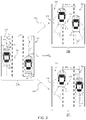
- an exemplary multi-lane roadway 219 may include a first lane 225 , a second lane 221 and an intermediate third lane 223 .
- Each lane has a respective width 207
- host vehicle 211 has a width W 1 203
- target vehicle 213 has a width W 2 205 .
- the host vehicle 211 may be traveling in the first lane 225 and the target vehicle may be travelling in the second lane 221 .
- Host and target vehicles 211 , 213 are initially laterally separated at time T 1 by distance D 1 201 .
- Distance D 1 is illustrated relative to longitudinal centerlines 215 , 217 ; however, lateral separation of the vehicles may be relative to any chosen datum including, for example, extreme vehicle width references.
- host and target vehicle 211 , 213 convergence upon the common intermediate lane 223 may be determined simply based upon detected separation changes between the vehicles over time.
- lateral vehicle separation may be determined by any suitable source of direct or synthesized range data from the various sensing systems employed on host vehicle 211 or combinationally and cooperatively with shared information between host vehicle 211 and target vehicle 213 , for example respective vehicle GPS positional data.
- relative lateral distance may be calculated using a sequence of images captured using a depth camera that has X,Y,Z coordinates in terms of image pixels. Therefore, at an initial time T 1 the distance D 1 is determined and at a future time T 2 a second lateral separation D 2 is determined.
- Initial distance determinations may be triggered by an event, for example an operator's intent as determined by a turn signal activation, steering input or vision system sensing lateral vehicle motion or drift relative to the current and adjacent lanes.
- Two exemplary mutually exclusive scenarios labeled 2 B and 2 C correspond to time T 2 and the progression of the travelling host and target vehicles 211 , 213 .
- scenario 2 B it is assumed that both vehicles have moved toward the intermediate lane 223 since time T 1 and the distance D 2 251 represents the lateral separation between the host and target vehicle 211 , 213 in scenario 2 B wherein there is a simultaneous lane change.
- scenario 2 C it is assumed that only the host vehicle 211 has moved toward the intermediate lane 223 since time T 1 and the target vehicle 213 has substantially maintained its lateral position within lane 221 since time T 1 .
- the distance D 2 253 represents the lateral separation between the host and target vehicles 211 , 213 in scenario 2 C wherein there is no simultaneous lane change.
- the change in separation between the host and target vehicles 211 , 213 may provide the basis for determining the relative lateral speed between the host and target vehicles 211 , 213 in accordance with the following relationships:
- Host vehicle 211 may provide its lateral speed V 1l from vehicle dynamics information or GPS information, for example.
- a comparison of the relative lateral speed ⁇ V to the host vehicle lateral speed V 1l may be made to determine whether the host and target vehicles 211 , 213 are simultaneously converging toward the intermediate lane. Where the relative lateral speed ⁇ V is greater than the host vehicle lateral speed V 1l , then it is determined that both vehicles are simultaneously moving toward the intermediate lane. This is the scenario of progression 260 from scene 2 A to 2 B of FIG. 2 . Where the relative lateral speed ⁇ V is not greater than the host vehicle lateral speed V 1l , then it is determined that only the host vehicle is moving toward the intermediate lane. This is the scenario of progression 270 from scene 2 A to 2 C of FIG. 2 .
- a collision evaluation may be performed. Based upon the results of the evaluation, operator or system control notifications may be made.
- FIG. 3 an initial scene labeled 3 A corresponding to an initial time T 0 which may correspond substantially to the time a collision evaluation is initiated. In one embodiment, this time T 0 substantially corresponds in time to the previously described determination that both vehicles are simultaneously moving toward the intermediate lane.
- the host vehicle is labeled 211 and the target vehicle is labeled 213 .
- Host and target vehicles 211 , 213 are initially laterally separated at time T 0 by distance D 0 301 .
- Distance D 0 is illustrated relative to longitudinal centerlines 215 , 217 .
- the host and target vehicles 211 , 213 are initially longitudinally separated at time T 0 by distance S 0 303 .
- Distance S 0 is illustrated relative to transverse centerlines 309 , 311 .
- the longitudinal separation of the vehicles may be relative to any chosen datum including, for example, extreme vehicle length references.
- Actual host vehicle heading may be represented by vector V 1 313 , which may further be represented by lateral component vector V 1l 317 at angle ⁇ to vector V 1 313 and longitudinal component vector V 1f 315 .
- Actual target vehicle heading may be represented by vector V 2 319 , which may further be represented by lateral component vector V 2l 323 at angle ⁇ to vector V 2 319 and longitudinal component vector V 2f 321 .
- a subsequent scene is labeled 3 B corresponding to a subsequent time T 1 which may correspond substantially to some arbitrary future time at which conditions for a collision may be determined to be satisfied given the initial conditions at time T 0 .
- a collision evaluation may be performed based upon as set of conditions which rely upon host and target vehicles 211 , 213 separation and speeds in accordance with the following inequalities: D 0 ⁇ t ( V 1l ⁇ V 2l ) ⁇ ( V 1l ⁇ V 2l ) ⁇ R , and [4] S 0 + ⁇ t ( V 1f ⁇ V 2f ) ⁇ ( V 1f ⁇ V 2f ) ⁇ R [5] wherein D 0 is the initial lateral separation between the host and target vehicles,
- a collision evaluation may be performed based upon as set of conditions which rely upon host and target vehicles 211 , 213 separation, speeds and geometries in accordance with the following inequalities:
- a collision evaluation may be performed based upon as set of conditions which rely upon host and target vehicles 211 , 213 separations, speeds and geometries, and lane geometries in accordance with the following inequalities:
- FIG. 4 illustrates an exemplary flowchart 400 of a method for predicting a collision between a host vehicle and a target vehicle operating on a multi-lane roadway, in accordance with the present disclosure.
- Flowchart 400 may generally represent steps in a routine implemented within one or more controllers as described herein.
- the routine begins at 401 and proceeds to 403 whereat a determination is made whether entry conditions are met. For example, host vehicle intent to change lane of travel may be determined or inferred, for example from user turn signal or steering wheel input, vision system input, autonomous or semi-autonomous control inputs, or other suitable means. If entry conditions are not met, then the routine may wait for an indication of such intent.
- the routine proceeds to 405 whereat various parameters useful in the collision prediction routine are received into the routine, for example a sequence of image based XYZ positions of the target vehicle, various sensed, communicated and calibration information set forth in the relationships and inequalities [1]-[11] described herein.
- the routine calculates relative lateral speed, for example as set forth in relationship [3] from the lateral separations, D 1 and D 2 , between the host and target vehicles corresponding to the times, T 1 and T 2 , as set forth in relationships [1] and [2] herein, respectively.
- Alternative lateral separation determinations may be made with image based calculations.
- the host vehicle lateral speed, V 1l may be compared with the relative lateral speed ⁇ V. Where the relative lateral speed ⁇ V is not greater than the host vehicle lateral speed V 1l , then it is determined that only the host vehicle is moving toward the intermediate lane and the routine returns to 403 to again wait for an indication of lane change intent. However, where the relative lateral speed ⁇ V is greater than the host vehicle lateral speed V 1l , then it is determined that both vehicles are simultaneously moving toward the intermediate lane and the routine continues at 411 . At 411 , evaluation of conditions is performed for the purpose of predicting a collision and to determine whether any operator or system control notifications may be made.
- 411 encompasses, for example, one or more of the various groupings of inequalities [4] and [5], [6] and [7], or [8] through [11] as set forth and described herein.
- One having ordinary skill in the art may recognize other relationship which may be implemented for the purpose of determining whether host and target vehicles are likely to collide in an intermediate lane during a simultaneous lane change.
- a predicted collision may result in an operator or system control notification at 413 , whereas no predicted collision may result in no such operator or system control notification at 415 .
- the routine may then exit at 417 .
- first and second elements can be a direct relationship where no other intervening elements are present between the first and second elements, but can also be an indirect relationship where one or more intervening elements are present (either spatially or functionally) between the first and second elements.
Landscapes
- Engineering & Computer Science (AREA)
- Automation & Control Theory (AREA)
- Transportation (AREA)
- Mechanical Engineering (AREA)
- Physics & Mathematics (AREA)
- General Physics & Mathematics (AREA)
- Traffic Control Systems (AREA)
Abstract
Description
wherein D0 is an initial lateral separation between the host and target vehicles, V1l is the host vehicle lateral speed, V2l is the target vehicle lateral speed, W1 is a width of the host vehicle, W2 is a width of the target vehicle, S0 is an initial longitudinal separation between the host and target vehicles, V1f is the host vehicle longitudinal speed, V2f is the target vehicle longitudinal speed, L1 is a length of the host vehicle, L2 is a length of the target vehicle, Δt is a time duration from an initial time to the collision, and C is a predetermined coefficient. The collision may be indicated where a Δt exists for which all inequalities are satisfied.
wherein D0 is an initial lateral separation between the host and target vehicles, V1l is the host vehicle lateral speed, V2l is the target vehicle lateral speed, W1 is a width of the host vehicle, W2 is a width of the target vehicle, α and β represent angles between respective vehicle headings and the roadway centerline, S0 is an initial longitudinal separation between the host and target vehicles, V1f is the host vehicle longitudinal speed, V2f is the target vehicle longitudinal speed, L1 is a length of the host vehicle, L2 is a length of the target vehicle, D1L is a longitudinal separation between the host vehicle and the adjacent intermediate lane, D2L is a longitudinal separation between the target vehicle and the adjacent intermediate lane, WL is lane width, and Δt is a time duration from an initial time to the collision. A collision is indicated where a Δt exists for which all inequalities are satisfied.
wherein ΔV is the relative lateral speed between the host and target vehicles.
D 0 −Δt(V 1l −V 2l)<(V 1l −V 2l)×R, and [4]
S 0 +Δt(V 1f −V 2f)<(V 1f −V 2f)×R [5]
wherein D0 is the initial lateral separation between the host and target vehicles,
-
- V1l is the host vehicle lateral speed,
- V2l is the target vehicle lateral speed,
- S0 is the initial longitudinal separation between the host and target vehicles,
- V1f is the host vehicle longitudinal speed,
- V2f is the target vehicle longitudinal speed,
- Δt is the time duration from an initial time to a predicted collision, and
- R is a predetermined reaction time.
A collision is predicted where a Δt exists for which both inequalities are satisfied.
wherein D0 is the initial lateral separation between the host and target vehicles,
-
- V1l is the host vehicle lateral speed,
- V2l is the target vehicle lateral speed,
- W1 is the width of the host vehicle,
- W2 is the width of the target vehicle,
- S0 is the initial longitudinal separation between the host and target vehicles,
- V1f is the host vehicle longitudinal speed,
- V2f is the target vehicle longitudinal speed,
- L1 is the length of the host vehicle,
- L2 is the length of the target vehicle,
- Δt is the time duration from an initial time to a predicted collision, and
- C is a predetermined coefficient determining a minimum margin distance.
A collision is predicted where a Δt exists for which both inequalities are satisfied.
wherein D0 is the initial lateral separation between the host and target vehicles,
-
- V1l is the host vehicle lateral speed,
- V2l is the target vehicle lateral speed,
- W1 is the width of the host vehicle,
- W2 is the width of the target vehicle,
- α and β represent angles between respective vehicle headings and the roadway centerline,
- S0 is the initial longitudinal separation between the host and target vehicles,
- V1f is the host vehicle longitudinal speed,
- V2f is the target vehicle longitudinal speed,
- L1 is the length of the host vehicle,
- L2 is the length of the target vehicle,
- D1L is the longitudinal separation between the host vehicle and the adjacent intermediate lane,
- D2L is the longitudinal separation between the target vehicle and the adjacent intermediate lane,
- WL is lane width, and
- Δt is the time duration from an initial time to a predicted collision.
A collision is predicted where a Δt exists for which all inequalities are satisfied.
Claims (16)
D 0 −Δt(V 1l −V 2l)<(V 1l −V 2l)×R, and
S 0 +Δt(V 1f −V 2f)<(V 1f −V 2f)×R,
D 0 −Δt(V 1l −V 2l)<(V 1l −V 2l)×R, and
S 0 +Δt(V 1f −V 2f)<(V 1f −V 2f)×R,
D 0 −Δt(V 1l −V 2l)<(V 1l −V 2l)×R, and
S 0 +Δt(V 1f −V 2f)<(V 1f −V 2f)×R,
Priority Applications (3)
| Application Number | Priority Date | Filing Date | Title |
|---|---|---|---|
| US16/791,066 US11400930B2 (en) | 2020-02-14 | 2020-02-14 | Simultaneous lane change situational awareness |
| DE102021100701.1A DE102021100701A1 (en) | 2020-02-14 | 2021-01-14 | SITUATIONAL AWARENESS FOR SIMULTANEOUSLY CHANGING LANES |
| CN202110155950.1A CN113269987B (en) | 2020-02-14 | 2021-02-04 | Simultaneous Lane Change Situational Awareness |
Applications Claiming Priority (1)
| Application Number | Priority Date | Filing Date | Title |
|---|---|---|---|
| US16/791,066 US11400930B2 (en) | 2020-02-14 | 2020-02-14 | Simultaneous lane change situational awareness |
Publications (2)
| Publication Number | Publication Date |
|---|---|
| US20210253095A1 US20210253095A1 (en) | 2021-08-19 |
| US11400930B2 true US11400930B2 (en) | 2022-08-02 |
Family
ID=77060954
Family Applications (1)
| Application Number | Title | Priority Date | Filing Date |
|---|---|---|---|
| US16/791,066 Active 2040-06-10 US11400930B2 (en) | 2020-02-14 | 2020-02-14 | Simultaneous lane change situational awareness |
Country Status (3)
| Country | Link |
|---|---|
| US (1) | US11400930B2 (en) |
| CN (1) | CN113269987B (en) |
| DE (1) | DE102021100701A1 (en) |
Families Citing this family (5)
| Publication number | Priority date | Publication date | Assignee | Title |
|---|---|---|---|---|
| KR20210035523A (en) * | 2019-09-24 | 2021-04-01 | 현대자동차주식회사 | Method and apparatus for vehicle driving control |
| US11535246B2 (en) * | 2020-03-30 | 2022-12-27 | Denso Corporation | Systems and methods for providing a warning to an occupant of a vehicle |
| DE102023104514A1 (en) | 2023-02-24 | 2024-08-29 | Bayerische Motoren Werke Aktiengesellschaft | Driver assistance system and driver assistance method for a vehicle |
| US20250304071A1 (en) * | 2024-04-01 | 2025-10-02 | Jilin University | Anthropomorphic lane-changing control method and system based on driving risk quantification, and vehicle |
| CN119160176B (en) * | 2024-09-12 | 2025-10-28 | 重庆赛力斯凤凰智创科技有限公司 | Vehicle lane change control method and device, electronic equipment and readable storage medium |
Citations (4)
| Publication number | Priority date | Publication date | Assignee | Title |
|---|---|---|---|---|
| US20170305422A1 (en) * | 2016-04-26 | 2017-10-26 | Toyota Jidosha Kabushiki Kaisha | Vehicle travel control apparatus |
| US20180188735A1 (en) * | 2015-09-30 | 2018-07-05 | Hitachi Automotive Systems, Ltd. | Lane change system |
| US20200039510A1 (en) * | 2017-04-26 | 2020-02-06 | Denso Corporation | Driver assist apparatus and driver assist program |
| US20200361455A1 (en) * | 2019-05-14 | 2020-11-19 | Toyota Jidosha Kabushiki Kaisha | Vehicle driving assist apparatus |
Family Cites Families (12)
| Publication number | Priority date | Publication date | Assignee | Title |
|---|---|---|---|---|
| JP2582766B2 (en) * | 1987-03-10 | 1997-02-19 | ブリティッシュ・テクノロジー・グループ・リミテッド | Automotive power unit |
| JP2002092795A (en) * | 2000-09-18 | 2002-03-29 | Toshiba Corp | Vehicle guidance device |
| GB0526669D0 (en) * | 2005-12-14 | 2006-02-15 | Wagner Wolfgang | Rail bound vehicle and traffic,mainly as toys |
| JP2014112348A (en) * | 2012-11-06 | 2014-06-19 | Daimler Ag | Action analyzing apparatus, action analyzing system, and action analyzing method |
| US8788134B1 (en) * | 2013-01-04 | 2014-07-22 | GM Global Technology Operations LLC | Autonomous driving merge management system |
| US20160121887A1 (en) * | 2014-11-04 | 2016-05-05 | Hyundai Motor Company | Apparatus and method for detecting collision object of vehicle |
| WO2018158873A1 (en) * | 2017-03-01 | 2018-09-07 | 本田技研工業株式会社 | Vehicle control apparatus, vehicle control method, and program |
| JP6958001B2 (en) * | 2017-06-09 | 2021-11-02 | トヨタ自動車株式会社 | Lane change support device |
| JP6861669B2 (en) * | 2018-06-15 | 2021-04-21 | 本田技研工業株式会社 | Vehicle control devices, vehicle control methods, and programs |
| CN109032131B (en) * | 2018-07-05 | 2021-07-27 | 东南大学 | A dynamic overtaking obstacle avoidance method applied to unmanned vehicles |
| CN110775060B (en) * | 2019-10-16 | 2021-03-30 | 南京信息工程大学 | A single-lane double-column small vehicle formation intelligent control system and formation method |
| CN110782703A (en) * | 2019-10-30 | 2020-02-11 | 长安大学 | Forward collision early warning method based on LTE-V communication |
-
2020
- 2020-02-14 US US16/791,066 patent/US11400930B2/en active Active
-
2021
- 2021-01-14 DE DE102021100701.1A patent/DE102021100701A1/en active Pending
- 2021-02-04 CN CN202110155950.1A patent/CN113269987B/en active Active
Patent Citations (4)
| Publication number | Priority date | Publication date | Assignee | Title |
|---|---|---|---|---|
| US20180188735A1 (en) * | 2015-09-30 | 2018-07-05 | Hitachi Automotive Systems, Ltd. | Lane change system |
| US20170305422A1 (en) * | 2016-04-26 | 2017-10-26 | Toyota Jidosha Kabushiki Kaisha | Vehicle travel control apparatus |
| US20200039510A1 (en) * | 2017-04-26 | 2020-02-06 | Denso Corporation | Driver assist apparatus and driver assist program |
| US20200361455A1 (en) * | 2019-05-14 | 2020-11-19 | Toyota Jidosha Kabushiki Kaisha | Vehicle driving assist apparatus |
Also Published As
| Publication number | Publication date |
|---|---|
| CN113269987A (en) | 2021-08-17 |
| CN113269987B (en) | 2023-06-02 |
| DE102021100701A1 (en) | 2021-08-19 |
| US20210253095A1 (en) | 2021-08-19 |
Similar Documents
| Publication | Publication Date | Title |
|---|---|---|
| US11400930B2 (en) | Simultaneous lane change situational awareness | |
| US8977420B2 (en) | Vehicle procession control through a traffic intersection | |
| US10829120B2 (en) | Proactive safe driving for an automated vehicle | |
| US10082791B2 (en) | Autonomous vehicle control system and method | |
| US10558217B2 (en) | Method and apparatus for monitoring of an autonomous vehicle | |
| US10678247B2 (en) | Method and apparatus for monitoring of an autonomous vehicle | |
| US11377145B2 (en) | Vehicle control device and control method for vehicle | |
| US11235757B2 (en) | Collision avoidance apparatus | |
| US11708069B2 (en) | Obstacle avoidance apparatus and obstacle avoidance route generating apparatus | |
| US10600257B2 (en) | Method and apparatus for monitoring of an autonomous vehicle | |
| US11433888B2 (en) | Driving support system | |
| US10632913B2 (en) | Vehicle behavior using information from other vehicles lights | |
| US20190066406A1 (en) | Method and apparatus for monitoring a vehicle | |
| JP2020021179A (en) | Driving support device | |
| US11590971B2 (en) | Apparatus and method for determining traveling position of vehicle | |
| US12024163B2 (en) | Systems and methods for generating vehicle alerts | |
| CN116704784A (en) | Method for Arbitrating Multiple Automatic Lane Change Requests Near Route Separation | |
| US20200385023A1 (en) | Vehicle control apparatus, vehicle, operation method of vehicle control apparatus, and non-transitory computer-readable storage medium | |
| EP4349674B1 (en) | Driving control method and driving control device | |
| US20240239345A1 (en) | Vehicle control apparatus and vehicle control method | |
| JP7048833B1 (en) | Vehicle control devices, vehicle control methods, and programs | |
| JP2023056344A (en) | Precedent vehicle selecting device | |
| US20250242827A1 (en) | In-vehicle display system and control method of in-vehicle display system | |
| US12459362B2 (en) | Display device | |
| WO2023053906A1 (en) | Vehicle control device |
Legal Events
| Date | Code | Title | Description |
|---|---|---|---|
| AS | Assignment |
Owner name: GM GLOBAL TECHNOLOGY OPERATIONS LLC, MICHIGAN Free format text: ASSIGNMENT OF ASSIGNORS INTEREST;ASSIGNORS:JIANG, MENG;ZHANG, JIYU;PERANANDAM, PRAKASH MOHAN;AND OTHERS;SIGNING DATES FROM 20200212 TO 20200213;REEL/FRAME:051822/0832 |
|
| FEPP | Fee payment procedure |
Free format text: ENTITY STATUS SET TO UNDISCOUNTED (ORIGINAL EVENT CODE: BIG.); ENTITY STATUS OF PATENT OWNER: LARGE ENTITY |
|
| STPP | Information on status: patent application and granting procedure in general |
Free format text: NON FINAL ACTION MAILED |
|
| STPP | Information on status: patent application and granting procedure in general |
Free format text: RESPONSE TO NON-FINAL OFFICE ACTION ENTERED AND FORWARDED TO EXAMINER |
|
| STPP | Information on status: patent application and granting procedure in general |
Free format text: NOTICE OF ALLOWANCE MAILED -- APPLICATION RECEIVED IN OFFICE OF PUBLICATIONS |
|
| STCF | Information on status: patent grant |
Free format text: PATENTED CASE |
|
| MAFP | Maintenance fee payment |
Free format text: PAYMENT OF MAINTENANCE FEE, 4TH YEAR, LARGE ENTITY (ORIGINAL EVENT CODE: M1551); ENTITY STATUS OF PATENT OWNER: LARGE ENTITY Year of fee payment: 4 |