US11400264B2 - Treatment system and method for enlarging narrow portion - Google Patents
Treatment system and method for enlarging narrow portion Download PDFInfo
- Publication number
- US11400264B2 US11400264B2 US16/839,297 US202016839297A US11400264B2 US 11400264 B2 US11400264 B2 US 11400264B2 US 202016839297 A US202016839297 A US 202016839297A US 11400264 B2 US11400264 B2 US 11400264B2
- Authority
- US
- United States
- Prior art keywords
- guide
- dilator
- treatment system
- distal end
- members
- Prior art date
- Legal status (The legal status is an assumption and is not a legal conclusion. Google has not performed a legal analysis and makes no representation as to the accuracy of the status listed.)
- Active, expires
Links
Images


Classifications
-
- A—HUMAN NECESSITIES
- A61—MEDICAL OR VETERINARY SCIENCE; HYGIENE
- A61M—DEVICES FOR INTRODUCING MEDIA INTO, OR ONTO, THE BODY; DEVICES FOR TRANSDUCING BODY MEDIA OR FOR TAKING MEDIA FROM THE BODY; DEVICES FOR PRODUCING OR ENDING SLEEP OR STUPOR
- A61M29/00—Dilators with or without means for introducing media, e.g. remedies
- A61M29/02—Dilators made of swellable material
-
- A—HUMAN NECESSITIES
- A61—MEDICAL OR VETERINARY SCIENCE; HYGIENE
- A61B—DIAGNOSIS; SURGERY; IDENTIFICATION
- A61B17/00—Surgical instruments, devices or methods
- A61B17/24—Surgical instruments, devices or methods for use in the oral cavity, larynx, bronchial passages or nose; Tongue scrapers
-
- A—HUMAN NECESSITIES
- A61—MEDICAL OR VETERINARY SCIENCE; HYGIENE
- A61M—DEVICES FOR INTRODUCING MEDIA INTO, OR ONTO, THE BODY; DEVICES FOR TRANSDUCING BODY MEDIA OR FOR TAKING MEDIA FROM THE BODY; DEVICES FOR PRODUCING OR ENDING SLEEP OR STUPOR
- A61M25/00—Catheters; Hollow probes
- A61M25/01—Introducing, guiding, advancing, emplacing or holding catheters
- A61M25/02—Holding devices, e.g. on the body
-
- A—HUMAN NECESSITIES
- A61—MEDICAL OR VETERINARY SCIENCE; HYGIENE
- A61M—DEVICES FOR INTRODUCING MEDIA INTO, OR ONTO, THE BODY; DEVICES FOR TRANSDUCING BODY MEDIA OR FOR TAKING MEDIA FROM THE BODY; DEVICES FOR PRODUCING OR ENDING SLEEP OR STUPOR
- A61M25/00—Catheters; Hollow probes
- A61M25/01—Introducing, guiding, advancing, emplacing or holding catheters
- A61M25/09—Guide wires
-
- A—HUMAN NECESSITIES
- A61—MEDICAL OR VETERINARY SCIENCE; HYGIENE
- A61M—DEVICES FOR INTRODUCING MEDIA INTO, OR ONTO, THE BODY; DEVICES FOR TRANSDUCING BODY MEDIA OR FOR TAKING MEDIA FROM THE BODY; DEVICES FOR PRODUCING OR ENDING SLEEP OR STUPOR
- A61M25/00—Catheters; Hollow probes
- A61M25/01—Introducing, guiding, advancing, emplacing or holding catheters
- A61M25/02—Holding devices, e.g. on the body
- A61M2025/0293—Catheter, guide wire or the like with means for holding, centering, anchoring or frictionally engaging the device within an artificial lumen, e.g. tube
-
- A—HUMAN NECESSITIES
- A61—MEDICAL OR VETERINARY SCIENCE; HYGIENE
- A61M—DEVICES FOR INTRODUCING MEDIA INTO, OR ONTO, THE BODY; DEVICES FOR TRANSDUCING BODY MEDIA OR FOR TAKING MEDIA FROM THE BODY; DEVICES FOR PRODUCING OR ENDING SLEEP OR STUPOR
- A61M25/00—Catheters; Hollow probes
- A61M25/01—Introducing, guiding, advancing, emplacing or holding catheters
- A61M25/09—Guide wires
- A61M2025/09008—Guide wires having a balloon
-
- A—HUMAN NECESSITIES
- A61—MEDICAL OR VETERINARY SCIENCE; HYGIENE
- A61M—DEVICES FOR INTRODUCING MEDIA INTO, OR ONTO, THE BODY; DEVICES FOR TRANSDUCING BODY MEDIA OR FOR TAKING MEDIA FROM THE BODY; DEVICES FOR PRODUCING OR ENDING SLEEP OR STUPOR
- A61M29/00—Dilators with or without means for introducing media, e.g. remedies
- A61M29/02—Dilators made of swellable material
- A61M2029/025—Dilators made of swellable material characterised by the guiding element
-
- A—HUMAN NECESSITIES
- A61—MEDICAL OR VETERINARY SCIENCE; HYGIENE
- A61M—DEVICES FOR INTRODUCING MEDIA INTO, OR ONTO, THE BODY; DEVICES FOR TRANSDUCING BODY MEDIA OR FOR TAKING MEDIA FROM THE BODY; DEVICES FOR PRODUCING OR ENDING SLEEP OR STUPOR
- A61M2205/00—General characteristics of the apparatus
- A61M2205/02—General characteristics of the apparatus characterised by a particular materials
- A61M2205/0216—Materials providing elastic properties, e.g. for facilitating deformation and avoid breaking
-
- A—HUMAN NECESSITIES
- A61—MEDICAL OR VETERINARY SCIENCE; HYGIENE
- A61M—DEVICES FOR INTRODUCING MEDIA INTO, OR ONTO, THE BODY; DEVICES FOR TRANSDUCING BODY MEDIA OR FOR TAKING MEDIA FROM THE BODY; DEVICES FOR PRODUCING OR ENDING SLEEP OR STUPOR
- A61M2210/00—Anatomical parts of the body
- A61M2210/06—Head
- A61M2210/0618—Nose
Definitions
- the present invention relates to a treatment system and a method for enlarging a narrow portion.
- U.S. Patent Application Publication No. 2017/0000981 and U.S. Patent Application Publication No. 2017/0000990 disclose devices for expanding a constricted area of a paranasal sinus by sequentially inserting a plurality of tapered pipes having different outer diameters.
- a treatment system includes a guide, a plurality of tubular dilator members, an operation portion, and a holding portion.
- the guide extends linearly or curvilinearly from a proximal end portion to a distal end portion.
- the plurality of tubular dilator members pass the guide inside and are configured to move forward along the guide.
- the operation portion is configured to sequentially move the plurality of dilator members from a side of the proximal end portion to a side of the distal end portion.
- the holding portion is provided on the guide. A distance between outer edges of the holding portion in a direction intersecting a direction from the side of the proximal end portion toward the side of the distal end portion of the guide is larger or is configured to be larger than a distance between outer edges of the guide.
- FIG. 1 is a schematic diagram showing an overall configuration of a treatment system according to a first embodiment, and showing first to third dilator members on a section cut along a plane passing through a longitudinal axis of a guide.
- FIG. 2 is a cross-sectional view taken along line F 2 -F 2 shown in FIG. 1 .
- FIG. 3 is a side view showing the first to third dilator members of the treatment system shown in FIG. 1 .
- FIG. 4 is a cross-sectional view showing the guide, the first to third dilator members, a cylinder, a holding portion, and first to third spring members of the treatment system shown in FIG. 1 .
- FIG. 5 is a cross-sectional view showing a state after the holding portion is expanded from a first state to a second state in the treatment system shown in FIG. 4 .
- FIG. 6 is a cross-sectional view showing a state in which the first dilator member is being advanced from the proximal end toward the distal end in the treatment system shown in FIG. 5 .
- FIG. 7 is a cross-sectional view showing a state after all of the first to third dilator members in the treatment system shown in FIG. 6 have been inserted into a narrow portion.
- FIG. 8 is a cross-sectional view showing a state after the first to third dilator members have been moved to the proximal end side by a retraction mechanism in the treatment system shown in FIG. 7 .
- FIG. 9 is a cross-sectional view showing a state after the guide in the treatment system shown in FIG. 8 has been pulled out of the narrow portion.
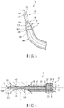
- FIG. 10 is a schematic diagram illustrating the holding portion in the first state in the treatment system according to a first modification of the first embodiment.
- FIG. 11 is a schematic diagram illustrating a state in which the diameter of the holding portion illustrated in FIG. 10 is increased to the second state.
- FIG. 12 is a schematic diagram illustrating the holding portion in the first state in the treatment system according to a second modification of the first embodiment.
- FIG. 13 is a schematic diagram illustrating a state in which the diameter of the holding portion illustrated in FIG. 12 is increased to the second state.
- FIG. 14 is a schematic diagram illustrating the holding portion in the first state in the treatment system according to a third modification of the first embodiment.
- FIG. 15 is a schematic diagram illustrating a state in which the diameter of the holding portion illustrated in FIG. 14 is increased to the second state.
- FIG. 16 is a schematic diagram illustrating the holding portion in the first state in the treatment system according to a fourth modification of the first embodiment.
- FIG. 17 is a schematic diagram illustrating a state in which the diameter of the holding portion illustrated in FIG. 16 is increased to the second state.
- FIG. 18 is a cross-sectional view showing a configuration of a guide, first to third dilator members, and a holding portion in a treatment system according to a second embodiment.
- FIG. 19 is a cross-sectional view showing a guide, first to third dilator members, and a holding portion (movable piece) of a treatment system according to a first modification of the second embodiment.
- FIG. 20 is a cross-sectional view showing a guide, first to third dilator members, and a holding portion (balloon-shaped member) of a treatment system according to a second modification of the second embodiment.
- FIG. 21 is a cross-sectional view showing a configuration of a guide, first to third dilator members, and a holding portion in a treatment system according to a third embodiment.
- FIG. 22 is a cross-sectional view showing a state after all of the first to third dilator members in the treatment system shown in FIG. 21 have been inserted into a narrow portion.
- FIG. 23 is a cross-sectional view showing a configuration of a guide, first to third dilator members, and a holding portion in a treatment system according to a fourth embodiment.
- FIG. 24 is a cross-sectional view showing a configuration of a guide, first to third dilator members, and a holding portion in a treatment system according to a fifth embodiment.
- FIGS. 1 to 9 a first embodiment of a treatment system 11 will be described with reference to FIGS. 1 to 9 .
- the treatment system 11 of the present embodiment is mainly inserted into a narrow portion (constricted area) 44 of a human body, for example, the narrow portion 44 formed at a boundary between a paranasal sinus and a nasal cavity and used for a treatment of expanding the narrow portion.
- the treatment system 11 includes a main body 12 , a fixed handle portion 13 extending from the main body 12 , a movable handle portion 14 rotatable with respect to the main body 12 , a guide 15 linearly or curvilinearly extending from the main body 12 , first to third dilator members 36 , 37 , and 38 that are cylindrical and provided outside the guide 15 , a cylindrical cylinder 16 rotatably provided around the guide 15 , a holding portion 18 fixed to a distal end portion 17 of the guide 15 , a leaf spring portion 24 (spring portion) interposed between the fixed handle portion 13 and the movable handle portion 14 , and first to third spring members (elastic members) 25 , 26 , and 27 incorporated in the cylinder 16 to advance the first to third dilator members 36 , 37 , and 38 .
- first to third spring members elastic members
- the main body 12 includes a hole 31 .
- the movable handle portion 14 has a rotation shaft 32 that fits inside the hole 31 of the movable handle portion 14 , and is configured to rotate with respect to the main body 12 around the hole 31 (rotation axis 32 ).
- the guide 15 includes a distal end portion 17 , a proximal end portion 33 opposite to the distal end portion 17 , and an intermediate portion 34 connecting the distal end portion 17 and the proximal end portion 33 .
- the guide 15 extends linearly or curvilinearly from the proximal end portion 33 to the distal end portion 17 .
- the longitudinal axis L of the guide 15 is defined as an axis (center axis) connecting the distal end portion 17 and the proximal end portion 33 .
- the distal end portion 33 is fixed to the main body 12 . As shown in FIG.
- FIG. 1 schematically illustrates the guide 15 as being straight.
- the leaf spring portion 24 can bias the movable handle portion 14 in a direction away from the fixed handle portion 13 .
- the cylinder 16 is formed as a revolver of a rotary pistol or a column having a lotus root-like cross section.
- the cylinder 16 has a plurality of (for example, three) through holes 35 , a second through hole provided at a central portion, through which the guide is passed, and a plurality of (for example, three) holding levers.
- the holding levers are respectively provided adjacent to the through holes 35 .
- Each of the holding levers is configured to hold any one of the first to third spring members 25 , 26 , and 27 in a compressed state.
- the plurality of through holes 35 are, for example, uniformly arranged at 120° intervals around the center axis of the cylinder 16 .
- the center axis of the cylinder 16 coincides with a longitudinal axis L of the guide 15 .
- the first spring member 25 is housed inside one through hole 35
- the second spring member 26 is housed inside another through hole 35
- the third spring member 27 is housed inside the other through holes 35 .
- the first to third dilator members 36 , 37 , and 38 pass the guide 15 inside, and are configured to move forward and backward along the guide 15 .
- the first dilator member 36 is located at the innermost position and is provided at a position adjacent to the guide 15 .
- the second dilator member 37 is provided at a position outside the first dilator member 36 .
- the third dilator member 38 is provided at a position outside the second dilator member 37 .
- the first to third dilator members 36 , 37 , and 38 are arranged concentrically.
- the first to third dilator members 36 , 37 , and 38 are arranged on a side of the proximal end portion 33 of the guide 15 in an initial state.
- the number of dilator members is not limited to three, and may be, for example, two or four or more.
- the first dilator member 36 is an example of a first member
- the second dilator member 37 is an example of
- the first dilator member 36 is configured to move forward and backward along the longitudinal axis L of the guide 15 .
- the first dilator member 36 has a first rigid portion 36 A provided on a side of the distal end portion 17 and a first flexible portion 36 B provided on the side of the proximal end portion 33 .
- the outer peripheral surface of the first rigid portion 36 A is formed in a tapered shape in which the diameter decreases, for example, toward the distal end portion 17 .
- the first rigid portion 36 A is formed of a rigid material, for example, a metal material.
- the first rigid portion 36 A is an example of a tapered portion that tapers toward the distal end portion 17 .
- the first flexible portion 36 B is formed, for example, in a cylindrical shape.
- the first flexible portion 36 B is formed of a flexible material, for example, a resin material or the like.
- the second dilator member 37 is configured to move forward and backward along the guide 15 .
- the second dilator member 37 has a second rigid portion 37 A provided on the side of the distal end portion 17 and a second flexible portion 37 B provided on the side of the proximal end portion 33 .
- the outer peripheral surface of the second rigid portion 37 A is formed in a tapered shape in which the diameter decreases, for example, toward the distal end portion 17 .
- the second rigid portion 37 A is formed of a rigid material, for example, a metal material.
- the second rigid portion 37 A is an example of a tapered portion that tapers toward the distal end portion 17 .
- the second flexible portion 37 B is formed, for example, in a cylindrical shape.
- the second flexible portion 37 B is formed of a flexible material, for example, a resin material or the like.
- the third dilator member 38 is configured to move forward and backward along the guide 15 .
- the third dilator member 38 has a third rigid portion 38 A provided on the side of the distal end portion 17 and a third flexible portion 38 B provided on the side of the proximal end portion 33 .
- the outer peripheral surface of the third rigid portion 38 A is formed in a tapered shape in which the diameter decreases, for example, toward the distal end portion 17 .
- the third rigid portion 38 A is formed of a rigid material, for example, a metal material.
- the third rigid portion 38 A is an example of a tapered portion that tapers toward the distal end portion 17 .
- the third flexible portion 38 B is formed, for example, in a cylindrical shape.
- the third flexible portion 38 B is formed of a flexible material, for example, a resin material or the like.
- the first spring member 25 is interposed between the first dilator member 36 and the movable handle portion 14 in a compressed state.
- the second spring member 26 is interposed between the second dilator member 37 and the movable handle portion 14 in a compressed state.
- the third spring member 27 is interposed between the third dilator member 38 and the movable handle portion 14 in a compressed state.
- the movable handle portion 14 includes a movable handle main body 41 , a release member 42 that is in contact with the holding levers and configured to release the compressed state of the first to third spring members 25 , 26 , and 27 , and a conversion mechanism 43 that converts a rotational movement of the movable handle main body 41 about the rotation axis into a rotational movement that rotates the cylinder 16 clockwise.
- the release member 42 is configured to release the compressed state of the first to third spring members 25 , 26 , and 27 by rotating the holding levers by abutting the respective holding levers.
- the first to third spring members 25 , 26 , and 27 whose compression state has been released can apply the repulsive force to the first to third dilator members 36 , 37 , and 38 .
- the movable handle portion 14 is grasped by the user, rotated toward the fixed handle portion 13 , and brought into contact with the fixed handle portion 13 , whereby the repulsive forces of the first to third spring members 25 , 26 , and 27 can be released one by one in order. More specifically, the movable handle portion 14 can release the repulsive force of the first spring member 25 when the movable handle portion 14 is grasped by the user and brought into contact with the fixed handle portion 13 for the first time. The movable handle portion 14 can release the repulsive force of the second spring member 26 when the movable handle portion 14 is grasped by the user and brought into contact with the fixed handle portion 13 for the second time. The movable handle portion 14 can release the repulsive force of the third spring member 27 when the movable handle portion 14 is grasped by the user and brought into contact with the fixed handle portion 13 for the third time.
- the conversion mechanism 43 includes a cam mechanism.
- the cam mechanism is configured to convert a back-and-forth movement of the movable handle portion 14 in the vicinity of the rotation axis 32 into a rotational movement for rotating the cylinder 16 clockwise by 120° when the movable handle portion 14 returns from the state of abutting the fixed handle portion 13 to the initial position by the repulsive force of the leaf spring portion 24 .
- a well-known structure can be used as the conversion mechanism 43 (cam mechanism).
- the conversion mechanism 43 (cam mechanism) may include an inclined surface provided on the cylinder 16 , and a prism-shaped contact piece provided on the movable handle portion 14 side and configured to abut the inclined surface at its distal end to rotate the cylinder 16 .
- the movable handle portion 14 and the first to third spring members 25 , 26 , and 27 are an example of an operation portion 20 configured to sequentially move the first to third dilator members 36 , 37 , and 38 from the side of the proximal end portion 33 to the side of the distal end portion 17 and insert the first to third dilator members 36 , 37 , and 38 into the narrow portion 44 .
- the holding portion 18 includes a distal end engagement portion provided on the side of the distal end portion 17 of the guide 15 .
- the holding portion 18 (distal end engagement portion) comprises a balloon-shaped member 18 A.
- the balloon-shaped member 18 A comprises a balloon formed of a rubbery elastic material.
- the balloon-shaped member 18 A can be suitably formed of a rubber material or the like.
- the holding portion 18 can be inflatable and deflatable.
- the holding portion 18 can be deformed between a first state S 1 having a diameter (distance between outer edges in a direction intersecting the longitudinal axis direction) equivalent to the diameter (inner diameter, distance between inner walls) of the narrow portion 44 located at the boundary between a paranasal sinus and a nasal cavity, and a second state S 2 having a larger diameter (distance between outer edges) than the first state S 1 .
- the operator inserts the guide 15 into the narrow portion 44 of the human body, for example, a boundary between a paranasal sinus and a nasal cavity.
- the narrow portion 44 is located at the entrance of the paranasal sinus, and forms a passage communicating with the paranasal sinus and the nasal cavity.
- the operator inserts the guide 15 through the external naris and positions the guide 15 in the paranasal sinus, for example in the frontal sinus or maxillary sinus. At this time, the guide 15 is inserted into the narrow portion 44 until the distal end portion 17 of the guide 15 is positioned deeper than the narrow portion 44 .
- the operator inflates the holding portion 18 from the first state S 1 shown in FIG. 4 to the second state S 2 shown in FIG. 5 , for example, by sending a fluid, such as air or water, to the holding portion 18 (balloon-shaped member 18 A) through the tubular guide 15 .
- a fluid such as air or water
- the distance between the outer edges of the balloon-like member 18 A orthogonal to the longitudinal axis L of the guide 15 (or the inner cross-sectional area) indicated by the reference symbol A 1 in FIG. 5 is larger than the distance between the outer edges of the distal end portion 17 of the guide 15 (or the inner cross-sectional area) indicated by the reference symbol A 2 in FIG. 5 .
- the holding portion 18 engages with the deep portion of the narrow portion 44 .
- the position of the guide 15 can be fixed with respect to the narrow portion 44 so that the guide 15 does not retract.
- the operator grasps the movable handle 14 to release the first spring member 25 from the compressed state, and causes the repulsive force of the first spring member 25 to act on the first dilator member 36 .
- the first dilator member 36 moves forward from the proximal end portion 33 to the distal end portion 17 and is inserted into the narrow portion 44 .
- the diameter (inner diameter) of the narrow portion 44 is increased.
- the movable handle portion 14 When the operator releases the grasp on the movable handle 14 after the insertion of the first dilator member 36 into the narrow portion 44 is completed, the movable handle portion 14 returns to the initial position by the action of the leaf spring portion 24 . At this time, the linear motion of the movable handle portion 14 in the vicinity of the rotation axis 32 is converted into a motion for rotating the cylinder 16 in the clockwise direction via the conversion mechanism (cam mechanism) 43 .
- the return operation of the movable handle portion 14 causes the cylinder 16 to rotate, for example, 120° in the clockwise direction.
- the rotation direction of the cylinder 16 may be the counterclockwise direction.
- the repulsive force of the second spring member 26 is caused to act on the second dilator member 37 .
- the second dilator member 37 moves forward from the proximal end portion 33 to the distal end portion 17 and is inserted into the narrow portion 44 and outside the first dilator member 36 .
- the diameter (inner diameter) of the narrow portion 44 is further increased.
- the movable handle portion 14 When the operator releases the grasp on the movable handle 14 after the insertion of the second dilator member 37 into the narrow portion 44 is completed, the movable handle portion 14 returns to the initial position by the action of the leaf spring portion 24 . At this time, the linear motion of the movable handle portion 14 in the vicinity of the rotation axis 32 is converted by the conversion mechanism.(cam mechanism) 43 , and the cylinder 16 rotates 120° in the clockwise direction.
- the repulsive force of the third spring member 27 is caused to act on the third dilator member 38 .
- the third dilator member 38 moves forward from the proximal end portion 33 to the distal end portion 17 and is inserted into the narrow portion 44 and outside the second dilator member 37 , as shown in FIG. 7 .
- the diameter (inner diameter) of the narrow portion 44 is further increased.
- the first to third dilator members 36 , 37 , and 38 are retracted toward the proximal end portion 33 by a retraction mechanism (not illustrated) as shown in FIG. 8 .
- the fluid such as air or water is recovered from the holding portion 18 , the holding portion 18 is changed from the second state S 2 to the first state S 1 , and the operator pulls the fixed handle 13 back to the near side.
- the guide 15 can be extracted from the narrow portion 44 such as a paranasal sinus.
- the treatment for enlarging the narrow portion 44 is completed.
- the treatment system 11 includes the guide 15 linearly extending from the proximal end portion 33 to the distal end portion 17 and inserted into the narrow portion 44 .
- the tubular dilator members 36 , 37 , and 38 pass the guide 15 inside and are configured to move forward along the guide 15 .
- the operation portion 20 is configured to move the plurality of dilator members 36 , 37 , and 38 from the side of the proximal end portion 33 to the side of the distal end portion 17 and to insert the plurality of dilator members 36 , 37 , and 38 into the narrow portion 44 .
- the holding portion 18 is provided on the guide 15 and is configured to hold the position of the guide 15 with respect to the narrow portion 44 .
- the reaction force generated when the dilator members 36 , 37 , and 38 are inserted into the narrow portion 44 can be received by the holding portion 18 . Therefore, it is possible to prevent the guide 15 from retracting due to the reaction force when the dilator members are to be moved forward. Thus, it is possible to prevent a problem wherein the treatment for enlarging the narrow portion 44 cannot be performed properly.
- Each of the plurality of dilator members has a tapered portion that tapers toward the distal end portion 17 . According to this configuration, the dilator members can be smoothly inserted into the narrow portion 44 .
- the holding portion 18 generates a holding force for holding the guide 15 at that position against a reaction force when the dilator members are inserted into the narrow portion 44 . According to this configuration, the holding portion 18 is not influenced by the reaction force generated when the dilator members are inserted into the narrow portion 44 , and the guide 15 can be prevented from retracting due to the reaction force when the dilator members are moved forward.
- the holding portion 18 includes the distal end engagement portion provided on the side of the distal end portion 17 of the guide 15 .
- the distal end engagement portion can change its diameter (distance between outer edges) between the first state S 1 having a diameter (distance between outer edges) equivalent to the diameter of the narrow portion 44 and the second state S 2 in which the distal end engagement portion can be engaged with the inner side of the narrow portion 44 by increasing its diameter from the first state S 1 .
- the holding portion 18 in the second state S 2 can prevent the guide 15 from retracting from the narrow portion 44 as much as possible.
- the distal end engagement portion includes a balloon-shaped member 18 A that is inflatable and deflatable between the first state S 1 and the second state S 2 .
- the holding portion 18 can be realized with a simple structure.
- the plurality of dilator members include the first dilator member 36 provided at a position adjacent to the guide 15 and the second dilator member 37 positioned outside the first dilator member.
- the operation portion 20 is configured to insert the second dilator member 37 outside the first member 36 into the narrow portion 44 in the state where the first member 36 has been inserted in the narrow portion 44 . According to this configuration, a treatment for gradually expanding the narrow portion 44 can be easily realized.
- a first modification of the first embodiment will be described with reference to FIGS. 10 and 11 .
- the configuration of the holding portion 18 (distal end engagement portion) is different from that of the first embodiment.
- the guide 15 is, for example, tubular.
- the holding portion 18 includes a shaft 45 configured to be inserted into and removed from the distal end portion 17 of the guide 15 , and a plurality of arc-shaped wires 46 that are connected between the distal end of the shaft 45 and the end of the main body 12 .
- the shaft 45 is configured to move forward and backward with respect to the guide 15 by a known mechanism (second operation portion).
- the wires 46 can be deformed from a first state S 1 in which the plurality of wires 46 are closed to the second state S 2 in which the plurality of wires 46 are unfolded to form a larger diameter than the first state S 1 .
- the distance between the outer edges of the wires 46 orthogonal to the longitudinal axis L of the guide 15 is greater than the distance between the outer edges of the distal end portions 17 of the guide 15 , indicated by the reference symbol A 2 in FIG. 11 .
- the plurality of wires 46 can be engaged with a deep portion beyond the narrow portion 44 . Accordingly, the same effect as in the first embodiment can be obtained.
- the configuration of the holding portion 18 (distal end engagement portion) is different from that of the first embodiment.
- the guide 15 is, for example, tubular.
- the holding portion 18 includes a pair of pivot plates 47 pivotable around the distal end portion 17 of the guide 15 , and a link mechanism 48 configured to pivot the pair of pivot plates 47 in the direction of increasing the distance between the plates.
- the link mechanism 48 is configured to move forward and backward with respect to the distal end portion 17 of the guide 15 by a known mechanism (second operation portion), and to project from and retract into the distal end portion 17 of the guide 15 .
- the pair of pivot plates 47 when the link mechanism 48 is projected from the distal end portion 17 of the guide 15 , the pair of pivot plates 47 can be pivoted from the first state S 1 (closed position) to the second state S 2 in which the distance is larger than that in the first state S 1 .
- the pair of pivot plates 47 By setting the pair of pivot plates 47 to the second state S 2 , the pair of pivot plates 47 can be engaged with a deep portion beyond the narrow portion 44 .
- the distance between the outer edges of the pivot plates 47 orthogonal to the longitudinal axis L of the guide 15 indicated by the reference symbol A 1 in FIG. 13 , is greater than the distance between the outer edges of the distal end portion 17 of the guide 15 , indicated by the reference symbol A 2 in FIG. 13 . Accordingly, the same effect as in the first embodiment can be obtained.
- a third modification of the first embodiment will be described with reference to FIGS. 14 and 15 .
- the configuration of the holding portion 18 (distal end engagement portion) is different from that of the first embodiment.
- the guide 15 is, for example, tubular.
- the holding portion 18 includes a pair of pivot plates 47 pivotable around the distal end portion 17 of the guide 15 , and a push rod 51 configured to project from and retract into the distal end portion 17 of the guide 15 .
- the push rod 51 is configured to move forward and backward with respect to the distal end portion 17 of the guide 15 by a known mechanism (second operation portion).
- a tip 52 of the push rod 51 can abut thick parts 47 A of the pivot plates 47 , and the distance between the distal ends of the pivot plates 47 can be increased by moving the push rod 51 forward (projecting the push rod 51 out of the main body 12 ).
- the pair of pivot plates 47 when the push rod 51 is projected from the guide 15 , the pair of pivot plates 47 can be pivoted from the first state S 1 (closed position) to the second state S 2 in which the distance between the distal ends of the pivot plates is larger than that in the first state S 1 .
- the pair of pivot plates 47 By setting the pair of pivot plates 47 to the second state S 2 , the pair of pivot plates 47 can be engaged with a deep portion beyond the narrow portion 44 .
- the distance between the outer edges of the pivot plates 47 orthogonal to the longitudinal axis L of the guide 15 indicated by the reference symbol A 1 in FIG. 15 , is greater than the distance between the outer edges of the distal end portion 17 of the guide 15 , indicated by the reference symbol A 2 in FIG. 15 . Accordingly, the same effect as in the first embodiment can be obtained.
- a fourth modification of the first embodiment will be described with reference to FIGS. 16 and 17 .
- the configuration of the holding portion 18 (distal end engagement portion) is different from that of the first embodiment.
- the guide 15 is, for example, tubular.
- the holding portion 18 includes a pair of elastic plates 53 having elasticity and fixed to the distal end portion 17 of the guide 15 , and a pull rod 54 configured to project from and retract into the distal end portion 17 of the guide 15 .
- a distance between the outer edges of a cross section intersecting a direction from the proximal end toward the distal end of the guide 15 is larger than a distance between inner edges of the elastic plates 53 at the distal end portion 17 of the guide 15 .
- the pull rod 54 is configured to move forward and backward with respect to the main body 12 by a known mechanism (second operation portion).
- the pair of elastic plates 53 when the pull rod 54 is retracted in the direction of being housed in the guide 15 , the pair of elastic plates 53 can be deformed from the first state S 1 (closed position) to the second state S 2 in which the distance between the elastic plates 53 is larger than that in the first state S 1 .
- the pair of elastic plates 53 By setting the pair of elastic plates 53 to the second state S 2 , the pair of elastic plates 53 can be engaged with a deep portion beyond the narrow portion 44 .
- the distance between the outer edges of the elastic plates 53 orthogonal to the longitudinal axis L of the guide 15 indicated by the reference symbol A 1 in FIG. 17 , is greater than the distance between the outer edges of the distal end portion 17 of the guide 15 , indicated by the reference symbol A 2 in FIG. 17 . Accordingly, the same effect as in the first embodiment can be obtained.
- a treatment system 11 according to a second embodiment will be described with reference to FIG. 18 .
- the configurations of first to third dilator members 36 , 37 , and 38 and the configuration of a holding portion 18 are different from those of the first embodiment, but the other parts are the same as those of the first embodiment.
- portions different from the first embodiment will be mainly described, and illustration or description of portions that are the same as those of the first embodiment will be omitted.
- first to third dilator members 36 , 37 , and 38 are each formed in a semi-cylindrical shape.
- One 180° portion around the guide 15 is covered with first to third dilator members 36 , 37 , and 38 , whereas the other 180° portion on the opposite side of the guide 15 is exposed.
- the first to third dilator members 36 , 37 , and 38 have the same configuration as that of the first embodiment, except that they are formed in a semi-cylindrical shape.
- the holding portion 18 is configured as an intermediate engagement portion provided at an intermediate portion 34 (a position between the distal end portion 17 and the proximal end portion 33 ) of the guide 15 .
- the holding portion 18 (intermediate engagement portion) comprises a plurality of irregularities (concavities and convexities) 18 A.
- the plurality of irregularities 18 A are preferably formed, for example, in a knurled shape.
- the holding portion 18 is biased in a direction of pressing against a narrow portion 44 as shown by an arrow, so that the holding portion 18 can bite into the inner surface of the narrow portion 44 .
- the holding portion 18 can be engaged with the inner surface of the narrow portion 44 .
- the plurality of irregularities 18 A are formed only in an angle range of 180° around a longitudinal axis L on the side where the first to third dilator members 36 , 37 , and 38 are not provided. Therefore, the first to third dilator members 36 , 37 , and 38 do not interfere with the plurality of irregularities 18 A.
- the operator inserts the guide 15 into the narrow portion 44 of a human body, for example, a paranasal sinus or the like.
- the operator inserts the guide 15 through the external naris and positions the guide 15 in the paranasal sinus, for example in the frontal sinus or maxillary sinus.
- the guide 15 is inserted into the narrow portion 44 until the distal end portion 17 of the guide 15 is positioned deeper than the narrow portion 44 .
- the operator biases the guide 15 so as to press the holding portion 18 (the intermediate engagement portion) against the inner surface of the narrow portion 44 .
- the holding portion 18 is engaged with the inner surface of the narrow portion 44 .
- the position of the guide 15 can be fixed with respect to the narrow portion 44 so that the guide 15 does not retract.
- the operator grasping the movable handle portion 14 , the operator inserts the first dilator member 36 , the second dilator member 37 , and the third dilator member 38 into the narrow portion 44 in this order by the repulsive forces of the first to third spring members 25 , 26 , and 27 , as in the above-described embodiment.
- the diameter (inner diameter) of the narrow portion 44 is gradually increased.
- the first to third dilator members 36 , 37 , and 38 are retracted toward the proximal end portion 33 by a retraction mechanism (not shown). Then, the biasing of the holding portion 18 onto the inner surface of the narrow portion 44 (the biasing in the direction of the arrow in FIG. 18 ) is released, and the operator pulls back the fixed handle portion 13 toward the operator side, whereby the guide 15 can be extracted out of the narrow portion 44 such as the paranasal sinuses. Thus, the treatment for enlarging the narrow portion 44 is completed.
- the holding portion 18 is the intermediate engagement portion provided at a position between the distal end portion 17 and the proximal end portion 33 of the guide 15 .
- the intermediate engagement portion is engageable with the inner surface of the narrow portion 44 . According to this configuration, it is possible to prevent the guide 15 from retracting from the narrow portion 44 by the intermediate engagement portion as much as possible.
- the intermediate engagement portion is a plurality of irregularities 18 A configured to be engaged with the inner surface of the narrow portion 44 .
- the guide 15 can be fixed to the inner surface of the narrow portion 44 by a simple technique of pressing the intermediate engagement portion formed of the irregularities 18 A against the inner surface of the narrow portion 44 .
- a first modification of the second embodiment will be described with reference to FIG. 19 .
- the configuration of the holding portion 18 (intermediate engagement portion) is different from that of the second embodiment.
- the holding portion 18 comprises a movable piece 55 configured to be housed inside the guide 15 or to protrude outward from the outer peripheral surface of the guide 15 .
- the movable piece 55 is formed in an angle range of 180° around the longitudinal axis L on the side where the first to third dilator members 36 , 37 , and 38 are not provided. Therefore, the first to third dilator members 36 , 37 , and 38 do not interfere with the movable piece 55 .
- the movable piece 55 includes a button portion 56 and a spring 57 for biasing the button portion 56 outward in the radial direction of the guide 15 .
- the button portion 56 is configured to move back and forth by the action of the spring 57 between a protruding position indicated by a solid line in FIG. 19 and a retracted position indicated by a two-dot chain line.
- the movable piece 55 can be engaged with the narrow portion 44 by moving to the protruding position and being pressed into the inner surface of the narrow portion 44 in the state of having entered the narrow portion 44 . Accordingly, the same effect as in the first embodiment can be obtained.
- the configuration of the holding portion is different from that of the second embodiment.
- the holding portion 18 (intermediate engagement portion) comprises a balloon-shaped member 18 A having a directivity in the inflation direction so as to inflate only in an angular range of 180° around the longitudinal axis L on the side where the first to third dilator members 36 , 37 , and 38 are not provided on the entire circumference of the guide 15 . Therefore, the first to third dilator members 36 , 37 , and 38 do not interfere with the balloon-shaped member 18 A.
- the balloon-shaped member 18 A comprises a balloon formed of a rubbery elastic material, and is inflatable and contractible.
- the balloon-shaped member 18 A can be suitably formed of a rubber material or the like.
- the balloon-shaped member 18 A can be deformed between a first state S 1 having a diameter (distance between outer edges in a direction intersecting the longitudinal axis direction) equivalent to the diameter (inner diameter) of the narrow portion 44 of a paranasal sinus, and a second state S 2 having a larger diameter (distance between outer edges) than the first state S 1 .
- the balloon-shaped member 18 A is inflated from the first state S 1 to the second state S 2 in the state where the balloon-shaped member 18 A has entered the narrow portion 44 , so that the balloon-shaped member 18 A can be engaged with the narrow portion 44 by being sunk into the inner surface of the narrow portion 44 . Accordingly, the same effect as in the first embodiment can be obtained.
- a treatment system 11 according to a third embodiment will be described with reference to FIGS. 21 and 22 .
- the configuration of a holding portion 18 is different from that of the first embodiment, but the other parts are the same as those of the first embodiment.
- portions different from the first embodiment will be mainly described, and illustration or description of portions that are the same as those of the first embodiment will be omitted.
- the holding portion 18 is formed in a cylindrical shape, and is provided around first to third dilator members 36 , 37 , and 38 . For this reason, the holding portion 18 covers the periphery of the first to third dilator members 36 , 37 , and 38 . A side of a distal end portion 33 of the holding portion 18 is fixed to the guide 15 . An abutting portion 18 A (abutting surface) that is inclined (tapered) so as to decrease in thickness toward the distal end portion 17 of the guide 15 is formed at the distal end of the holding portion 18 .
- the abutting portion 18 A (abutting surface) be flush with the surface formed by the distal ends of the first to third dilator members 36 , 37 , and 38 .
- the holding portion 18 can abut on a proximal side of an entrance of the narrow portion 44 at the abutting portion 18 A.
- the operator inserts the guide 15 into a narrow portion 44 of the human body, for example into a paranasal sinus or the like.
- the operator inserts the guide 15 through the external naris and positions the guide 15 in the paranasal sinus, for example in the frontal sinus or maxillary sinus.
- the guide 15 is inserted until the distal end portion 17 of the guide 15 is positioned deeper than the narrow portion 44 .
- the operator biases the movable handle portion 14 in a direction approaching the patient.
- the abutting portion 18 A of the holding portion 18 is brought into contact with a position on the proximal side of the entrance of the narrow portion 44 .
- the operator maintains a biased state of the movable handle portion 14 , whereby the position of the guide 15 can be fixed with respect to the narrow portion 44 so that the guide 15 does not retract. In this state, by grasping the movable handle portion 14 , as shown in FIG.
- the operator inserts the first dilator member 36 , the second dilator member 37 , and the third dilator member 38 into the narrow portion 44 in this order by the repulsive forces of the first to third spring members 25 , 26 , and 27 , as in the above-described embodiments.
- the diameter (inner diameter) of the narrow portion 44 is gradually increased.
- a reaction force acts on the guide 15 .
- the holding portion 18 is pressed against the narrow portion 44 via the abutting portion 18 A, the guide 15 is prevented from retracting due to the reaction force.
- the first to third dilator members 36 , 37 , and 38 are retracted toward the proximal end portion 33 by a retraction mechanism (not shown). Then, the biasing of the holding portion 18 onto the proximal side of the entrance of the narrow portion 44 is released, and the operator pulls back the fixed handle portion 13 toward the operator side, whereby the guide 15 can be extracted out of the narrow portion 44 such as the paranasal sinuses. Thus, the treatment for enlarging the narrow portion 44 is completed.
- the holding portion 18 includes the abutting portion 18 A configured to be brought into contact with a position on the proximal side of the entrance of the narrow portion 44 .
- the position of the guide 15 with respect to the narrow portion 44 can be fixed by the holding portion 18 .
- the reaction force generated when the dilator members are inserted into the narrow portion 44 can be received by the holding portion 18 , and the guide 15 can be prevented from retracting due to the reaction force when the dilator members are to be moved forward.
- the abutting portion 18 A of the holding portion 18 is brought into contact with a position on the proximal side of the entrance of the narrow portion 44 , but the position where the abutting portion 18 A is brought into contact is not limited to this.
- the position of the guide 15 may be maintained by bringing the abutting portion 18 A around the entrance of the nasal cavity (external naris) or the like.
- a treatment system 11 according to a fourth embodiment will be described with reference to FIG. 23 .
- the configuration of a holding portion 18 is different from that of the first embodiment, but the other parts are the same as those of the first embodiment.
- portions different from the first embodiment will be mainly described, and illustration or description of portions that are the same as those of the first embodiment will be omitted.
- the holding portion 18 includes a proximal end engagement portion provided on the side of the proximal end portion 33 of the guide 15 .
- the holding portion 18 (proximal end engagement portion) comprises a balloon-shaped member 18 A.
- the balloon-shaped member 18 A comprises a balloon formed of a rubbery elastic material.
- the balloon-shaped member 18 A can be suitably formed of a rubber material or the like.
- the holding portion 18 can be inflatable and deflatable.
- the holding portion 18 is located inside a nasal cavity 61 and near an external naris 62 when the guide 15 is inserted into the narrow portion 44 of the paranasal sinus.
- the holding portion 18 can be deformed between a first state S 1 that is a deflated state and a second state S 2 having a larger diameter (distance between outer edges) than the first state S 1 .
- the nasal cavity 61 is an example of a sinus which the holding portion 18 in the second state S 2 engages with.
- the operator inserts the guide part 15 into a narrow portion 44 of the human body, for example into a paranasal sinus or the like.
- the operator inserts the guide 15 through the external naris 62 and positions the guide 15 in the paranasal sinus, for example in the frontal sinus or maxillary sinus.
- the guide 15 is inserted into the narrow portion 44 until the distal end portion 17 of the guide 15 is positioned deeper than the narrow portion 44 .
- the operator inflates the holding portion 18 (balloon-shaped member 18 A) from the first state S 1 to the second state S 2 by sending a fluid such as air or water to the holding portion 18 .
- a fluid such as air or water
- the holding portion 18 is engaged with the inner wall of the nasal cavity 61 (sinus) near the external naris 62 . Accordingly, the position of the guide 15 can be fixed with respect to the narrow portion 44 so that the guide 15 does not retract.
- the operator inserts the first dilator member 36 , the second dilator member 37 , and the third dilator member 38 into the narrow portion 44 in this order by the repulsive forces of the first to third spring members 25 , 26 , and 27 , as in the above-described embodiment.
- the diameter (inner diameter) of the narrow portion 44 is gradually increased.
- a reaction force acts on the guide 15 .
- the guide 15 is prevented from retracting due to the reaction force.
- the first to third dilator members 36 , 37 , and 38 are retracted toward the proximal end portion 33 by a retraction mechanism (not shown). Then, the balloon-like member 18 A is contracted from the second state S 2 to the first state S 1 , and the operator pulls back the fixed handle portion 13 toward the operator's side, whereby the guide 15 can be extracted out of the narrow portion such as the paranasal sinuses. Thus, the treatment for enlarging the narrow portion 44 is completed.
- the holding portion 18 is a proximal end engagement portion provided on the side of the proximal end portion 33 of the guide 15 .
- the proximal end engagement portion is configured to change the diameter (distance between outer edges) between a first state S 1 having a predetermined diameter (distance between outer edges) and a second state S 2 in which the diameter is larger than that in the first state S 1 and to engage with the inner surface of the sinus on the proximal side of the entrance of the narrow portion 44 .
- the proximal end engagement portion is a balloon-shaped member 18 A that is inflatable and deflatable between the first state S 1 and the second state S 2 . According to this configuration, the proximal end engagement portion can be realized with a simple structure.
- a treatment system 11 according to a fifth embodiment will be described with reference to FIG. 24 .
- the configuration of a holding portion 18 is different from that of the first embodiment, but the other parts are the same as those of the first embodiment.
- portions different from the first embodiment will be mainly described, and illustration or description of portions that are the same as those of the first embodiment will be omitted.
- the holding portion 18 is a proximal end engagement portion provided on the side of the proximal end portion 33 of the guide 15 .
- the holding portion 18 (proximal end engagement portion) is formed in an arm shape that supports the main body 12 .
- the holding portion 18 preferably has a plurality of joints so that the position of the guide section 15 can be finely adjusted.
- the plurality of joints can switch between a free state in which the angle can be freely changed and a restricted state in which the current angle is maintained. Switching between the free state and the restricted state may be realized by, for example, screwing a screw or the like or bringing a brake into contact with a rotating shaft or the like.
- the holding portion 18 is fixed to a fixed object 63 such as a bed or a chair on which the patient is placed.
- the operator inserts the guide 15 into a narrow portion 44 of the human body, for example into a paranasal sinus or the like.
- the operator inserts the guide 15 through the external naris 62 and positions the guide 15 in the paranasal sinus, for example in the frontal sinus or maxillary sinus.
- the guide 15 is inserted into the narrow portion 44 until the distal end portion 17 of the guide 15 is positioned deeper than the narrow portion 44 .
- the operator switches each joint of the holding portion 18 from the free state to the restricted state.
- the positions of the main body 12 and the guide 15 are fixed.
- the position of the guide 15 can be fixed with respect to the narrow portion 44 so that the guide 15 does not retract.
- the operator grasping the movable handle portion 14 , the operator inserts the first dilator member 36 , the second dilator member 37 , and the third dilator member 38 into the narrow portion 44 in this order by the repulsive forces of the first to third spring members 25 , 26 , and 27 , as in the above-described embodiment.
- the diameter (inner diameter) of the narrow portion 44 is gradually increased.
- a reaction force acts on the guide 15 .
- the guide 15 is prevented from retracting due to the reaction force.
- the first to third dilator members 36 , 37 , and 38 are retracted toward the proximal end portion 33 by a retraction mechanism (not shown). Then, the joints of the holding portion 18 are released from the restricted state to the free state, and the operator pulls back the fixed handle portion 13 toward the operator side, whereby the guide 15 can be extracted out of the narrow portion 44 such as the paranasal sinuses. Thus, the treatment for enlarging the narrow portion 44 is completed.
- the holding portion 18 is a proximal end engagement portion provided on the side of the proximal end portion 33 of the guide 15 .
- the proximal end engagement portion is fixed to the fixed object 63 on which the patient is placed.
- the position of the guide 15 can be fixed with respect to the narrow portion 44 by a method of fixing the proximal end engagement portion to a structure outside the body of the patient without fixing the proximal end engagement portion to the body of the patient.
- a reaction force generated when the dilator members are inserted into the narrow portion 44 can be received by the holding portion 18 , and the guide 15 can be prevented from retracting due to the reaction force when the dilator members are to be moved forward.
Landscapes
- Health & Medical Sciences (AREA)
- Life Sciences & Earth Sciences (AREA)
- Public Health (AREA)
- Veterinary Medicine (AREA)
- Biomedical Technology (AREA)
- Heart & Thoracic Surgery (AREA)
- Engineering & Computer Science (AREA)
- Animal Behavior & Ethology (AREA)
- General Health & Medical Sciences (AREA)
- Hematology (AREA)
- Anesthesiology (AREA)
- Pulmonology (AREA)
- Biophysics (AREA)
- Surgery (AREA)
- Vascular Medicine (AREA)
- Dentistry (AREA)
- Oral & Maxillofacial Surgery (AREA)
- Otolaryngology (AREA)
- Nuclear Medicine, Radiotherapy & Molecular Imaging (AREA)
- Medical Informatics (AREA)
- Molecular Biology (AREA)
- Media Introduction/Drainage Providing Device (AREA)
- Surgical Instruments (AREA)
Abstract
Description
Claims (20)
Applications Claiming Priority (1)
| Application Number | Priority Date | Filing Date | Title |
|---|---|---|---|
| PCT/JP2017/036712 WO2019073529A1 (en) | 2017-10-10 | 2017-10-10 | Treatment system |
Related Parent Applications (1)
| Application Number | Title | Priority Date | Filing Date |
|---|---|---|---|
| PCT/JP2017/036712 Continuation WO2019073529A1 (en) | 2017-10-10 | 2017-10-10 | Treatment system |
Publications (2)
| Publication Number | Publication Date |
|---|---|
| US20200230383A1 US20200230383A1 (en) | 2020-07-23 |
| US11400264B2 true US11400264B2 (en) | 2022-08-02 |
Family
ID=66100485
Family Applications (1)
| Application Number | Title | Priority Date | Filing Date |
|---|---|---|---|
| US16/839,297 Active 2038-04-11 US11400264B2 (en) | 2017-10-10 | 2020-04-03 | Treatment system and method for enlarging narrow portion |
Country Status (2)
| Country | Link |
|---|---|
| US (1) | US11400264B2 (en) |
| WO (1) | WO2019073529A1 (en) |
Families Citing this family (1)
| Publication number | Priority date | Publication date | Assignee | Title |
|---|---|---|---|---|
| CN116942999A (en) * | 2023-06-13 | 2023-10-27 | 珠海拓爱医疗科技有限公司 | A kind of foreskin expansion device and foreskin expansion method |
Citations (7)
| Publication number | Priority date | Publication date | Assignee | Title |
|---|---|---|---|---|
| US4230109A (en) * | 1978-08-21 | 1980-10-28 | Alan Geiss | Apparatus for securing couplings of intravenous and intra-arterial access systems |
| US6488653B1 (en) * | 1999-08-12 | 2002-12-03 | Wilson-Cook Medical Incorporated | Dilation balloon having multiple diameters |
| JP2008513125A (en) | 2004-09-17 | 2008-05-01 | アクラレント インコーポレイテッド | Devices and methods for dilating and modifying sinuses and other intranasal or paranasal cavities |
| JP2008295729A (en) | 2007-05-31 | 2008-12-11 | Olympus Medical Systems Corp | Cutting tool |
| US20100274275A1 (en) | 2009-04-27 | 2010-10-28 | Heinz Stammberger | Medical instrument for dilating osseous structures |
| US20170000990A1 (en) * | 2015-06-30 | 2017-01-05 | Lawrence J. Gerrans | Sinus Ostia Dilation System |
| US20170000981A1 (en) | 2015-06-30 | 2017-01-05 | Lawrence J. Gerrans | Body Cavity Dilation System |
-
2017
- 2017-10-10 WO PCT/JP2017/036712 patent/WO2019073529A1/en not_active Ceased
-
2020
- 2020-04-03 US US16/839,297 patent/US11400264B2/en active Active
Patent Citations (7)
| Publication number | Priority date | Publication date | Assignee | Title |
|---|---|---|---|---|
| US4230109A (en) * | 1978-08-21 | 1980-10-28 | Alan Geiss | Apparatus for securing couplings of intravenous and intra-arterial access systems |
| US6488653B1 (en) * | 1999-08-12 | 2002-12-03 | Wilson-Cook Medical Incorporated | Dilation balloon having multiple diameters |
| JP2008513125A (en) | 2004-09-17 | 2008-05-01 | アクラレント インコーポレイテッド | Devices and methods for dilating and modifying sinuses and other intranasal or paranasal cavities |
| JP2008295729A (en) | 2007-05-31 | 2008-12-11 | Olympus Medical Systems Corp | Cutting tool |
| US20100274275A1 (en) | 2009-04-27 | 2010-10-28 | Heinz Stammberger | Medical instrument for dilating osseous structures |
| US20170000990A1 (en) * | 2015-06-30 | 2017-01-05 | Lawrence J. Gerrans | Sinus Ostia Dilation System |
| US20170000981A1 (en) | 2015-06-30 | 2017-01-05 | Lawrence J. Gerrans | Body Cavity Dilation System |
Non-Patent Citations (2)
| Title |
|---|
| English translation of International Preliminary Report on Patentability dated Apr. 14, 2020, together with the Written Opinion received in related International Application No. PCT/JP2017/036712. |
| International Search Report dated Jan. 9, 2018 issued in International Application No. PCT/JP2017/036712. |
Also Published As
| Publication number | Publication date |
|---|---|
| WO2019073529A1 (en) | 2019-04-18 |
| US20200230383A1 (en) | 2020-07-23 |
Similar Documents
| Publication | Publication Date | Title |
|---|---|---|
| US8523763B2 (en) | Lumen probe apparatuses and methods for using the same | |
| KR101843342B1 (en) | Apparatus for treating disorders of the sinuses | |
| US6939291B2 (en) | Endoscopic device for locomotion through the gastro-intestinal tract | |
| CN105530879B (en) | Laparoscopic clamp assembly | |
| KR100367723B1 (en) | Writing instrument with variable contour grip arrangement | |
| US20080039865A1 (en) | Maasal cervical dilator | |
| US20040243144A1 (en) | Device | |
| CN108778161A (en) | Dilating catheter component with quick variation component | |
| US11400264B2 (en) | Treatment system and method for enlarging narrow portion | |
| CA2343764A1 (en) | A handle for manipulation of a stylet used for deflecting a tip of a lead or catheter | |
| JPH02297381A (en) | Cardiac function aid air-bladder and inserting method therefor | |
| JP2019533530A (en) | Expansion device comprising a malleable feature and a device for bending the malleable feature | |
| CN103565518A (en) | Double-control bent electrophysiological catheter | |
| EP3609414A1 (en) | Capture devices | |
| JP2021511093A (en) | Intravascular device | |
| US11607328B2 (en) | Device and method for safely positioning a coronary stent in the coronary arteries | |
| JP5179413B2 (en) | Endoscope guide tube device | |
| US20090234281A1 (en) | Fluid feeder and balloon catheter | |
| US9072582B2 (en) | Rectocele device | |
| CN212281519U (en) | A femoral positioning device with adjustable osteotomy volume | |
| WO2020039576A1 (en) | Medical manipulator system and access device | |
| WO2023116369A1 (en) | Delivery system and control handle thereof | |
| JP2012050490A (en) | Wire operation device | |
| CN113616149A (en) | Enteroscope and using method thereof | |
| CN222150117U (en) | Auxiliary device for internal fixation of titanium cable for patella fracture |
Legal Events
| Date | Code | Title | Description |
|---|---|---|---|
| AS | Assignment |
Owner name: OLYMPUS CORPORATION, JAPAN Free format text: ASSIGNMENT OF ASSIGNORS INTEREST;ASSIGNOR:YOSHINO, MASAHIRO;REEL/FRAME:052304/0424 Effective date: 20200311 |
|
| FEPP | Fee payment procedure |
Free format text: ENTITY STATUS SET TO UNDISCOUNTED (ORIGINAL EVENT CODE: BIG.); ENTITY STATUS OF PATENT OWNER: LARGE ENTITY |
|
| STPP | Information on status: patent application and granting procedure in general |
Free format text: APPLICATION DISPATCHED FROM PREEXAM, NOT YET DOCKETED |
|
| STPP | Information on status: patent application and granting procedure in general |
Free format text: DOCKETED NEW CASE - READY FOR EXAMINATION |
|
| STPP | Information on status: patent application and granting procedure in general |
Free format text: NON FINAL ACTION MAILED |
|
| STPP | Information on status: patent application and granting procedure in general |
Free format text: RESPONSE TO NON-FINAL OFFICE ACTION ENTERED AND FORWARDED TO EXAMINER |
|
| STPP | Information on status: patent application and granting procedure in general |
Free format text: NOTICE OF ALLOWANCE MAILED -- APPLICATION RECEIVED IN OFFICE OF PUBLICATIONS |
|
| STCF | Information on status: patent grant |
Free format text: PATENTED CASE |
|
| MAFP | Maintenance fee payment |
Free format text: PAYMENT OF MAINTENANCE FEE, 4TH YEAR, LARGE ENTITY (ORIGINAL EVENT CODE: M1551); ENTITY STATUS OF PATENT OWNER: LARGE ENTITY Year of fee payment: 4 |