US11399566B2 - Aerosol generating device - Google Patents
Aerosol generating device Download PDFInfo
- Publication number
- US11399566B2 US11399566B2 US16/943,780 US202016943780A US11399566B2 US 11399566 B2 US11399566 B2 US 11399566B2 US 202016943780 A US202016943780 A US 202016943780A US 11399566 B2 US11399566 B2 US 11399566B2
- Authority
- US
- United States
- Prior art keywords
- cigarette
- aerosol generating
- case
- generating device
- heater
- Prior art date
- Legal status (The legal status is an assumption and is not a legal conclusion. Google has not performed a legal analysis and makes no representation as to the accuracy of the status listed.)
- Active
Links
Images


Classifications
-
- A—HUMAN NECESSITIES
- A24—TOBACCO; CIGARS; CIGARETTES; SIMULATED SMOKING DEVICES; SMOKERS' REQUISITES
- A24F—SMOKERS' REQUISITES; MATCH BOXES; SIMULATED SMOKING DEVICES
- A24F40/00—Electrically operated smoking devices; Component parts thereof; Manufacture thereof; Maintenance or testing thereof; Charging means specially adapted therefor
- A24F40/40—Constructional details, e.g. connection of cartridges and battery parts
-
- A—HUMAN NECESSITIES
- A24—TOBACCO; CIGARS; CIGARETTES; SIMULATED SMOKING DEVICES; SMOKERS' REQUISITES
- A24F—SMOKERS' REQUISITES; MATCH BOXES; SIMULATED SMOKING DEVICES
- A24F40/00—Electrically operated smoking devices; Component parts thereof; Manufacture thereof; Maintenance or testing thereof; Charging means specially adapted therefor
- A24F40/20—Devices using solid inhalable precursors
Definitions
- One or more exemplary embodiments of the present disclosure relate to an aerosol generating device, and more particularly, to an aerosol generating device having a structure that a user is unable to disassemble arbitrarily.
- a non-combustion aerosol generating device refers to an apparatus which generates aerosols from an aerosol generating material included in a cigarette by heating the cigarette to a certain temperature without burning the cigarette, and allows a user to inhale the generated aerosols with air.
- the non-combustion aerosol generating device is provided with a heater for heating the cigarette therein. Since the heater is heated to a high temperature, when the user disassembles the apparatus arbitrarily, the user may be easily exposed to a risk of being burned.
- One or more exemplary embodiments of the present disclosure provide an aerosol generating device having a structure that a user is unable to disassemble arbitrarily.
- one or more exemplary embodiments of the present disclosure may provide aerosols containing rich flavors, nicotine, and the like by passing the aerosols generated by heating an aerosol generating source through a cigarette.
- An exemplary embodiment of the present disclosure provides an aerosol generating device including: a case in which a heater for heating a cigarette is installed; a bracket for supporting components installed inside the case; a fastening member for fastening the case and the bracket; and a cap that is installed on an outer surface of the case in an inseparable manner to conceal the fastening member in the case.
- the cap includes a hook portion protruding in the lengthwise direction of the cigarette, wherein the hook portion may include a locking jaw protruding toward the inner surface of the case.
- the case may include a seating portion protruding toward the hook portion to seat the cap.
- the seating portion when the cap is installed in the case, the seating portion may be engaged with the locking jaw, thus restricting upward movement of the cap upward.
- the surface where the seating portion and the locking jaw contact each other may be extended in a direction parallel to the width direction of the cigarette.
- the aerosol generating device may further include a stopper that is installed on the inner surface of the case, presses the hook portion in the direction in which the locking jaw protrudes, and thus restricts movement of the hook portion in the direction in which the seating portion protrudes.
- the locking jaw may include an inclined surface such that the seating portion slides on the inclined surface while the cap is being installed in the case.
- the seating portion may include a sliding surface such that the locking jaw slides on the sliding surface while the cap is being installed in the case.
- the aerosol generating device may further include a sealing member interposed between the case and the cap to seal the inside of the case.
- the case includes an upper case where the cigarette is inserted and heated and a lower case supporting and protecting various components installed therein, wherein the contact surfaces of the upper case and the cap, and of the upper case and the lower case may be joined by ultrasonic welding.
- the hook portion further includes an extension member extending in the lengthwise direction of the cigarette further than the locking jaw, and the stopper may press the extension member in the direction in which the locking jaw protrudes.
- the length of the extension member may be greater than the distance from the stopper to the surface where the seating portion and the cap contact each other.
- the width of the locking jaw may be less than or equal to the distance from the surface where the locking jaw and the seating portion engage with each other to the stopper.
- the width of the hook portion excluding the locking jaw may be less than the distance from the stopper to the locking jaw.
- the width of the hook portion including the locking jaw may be greater than the distance from the stopper to the locking jaw.
- one or more exemplary embodiments of the present disclosure may provide an aerosol generating device having a structure that a user is unable to disassemble arbitrarily since the user is unable to have access to a fastening member installed in a case due to an inseparable coupling structure of the case and cap.
- the aerosol generating device may provide aerosols containing flavors, nicotine, and the like suitable for the user by passing the flow of the aerosols generated from an aerosol generating source through a cigarette.
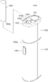
- FIGS. 1 through 3 are diagrams showing examples in which a cigarette is inserted into an aerosol generating device.
- FIG. 4 illustrates an example of the cigarette.
- FIG. 5 is a perspective view illustrating an operating state of the aerosol generating device according to an exemplary embodiment.
- FIG. 6 is a perspective view illustrating an operating state in which some components are separated from the aerosol generating device, according to the exemplary embodiment shown in FIG. 5 .
- FIG. 7 is an exploded perspective view illustrating some components of the aerosol generating device disassembled, according to the exemplary embodiment shown in FIG. 5 .
- FIG. 8 is a cross-sectional view illustrating a coupling relationship of some components of the aerosol generating device, according to the exemplary embodiment shown in FIG. 5 .
- FIG. 9 is a cross-sectional view illustrating a modified example of some components of the aerosol generating device, according to the exemplary embodiment shown in FIG. 8 .
- An exemplary embodiment of the present disclosure provides an aerosol generating device including: a case in which a heater for heating a cigarette is installed; a bracket for supporting components installed in the case; a fastening member for fastening the case and the bracket; and a cap that is installed on the outer surface of the case to conceal the fastening member in the case, and inseparable after installation.
- the general terms which are currently and widely used are selected in consideration of functions of structural elements in the various exemplary embodiments of the present disclosure.
- meanings of the terms can be changed according to intention, a judicial precedence, the appearance of a new technology, and the like.
- a term which is not commonly used can be selected. In such a case, the meaning of the term will be described in detail at the corresponding portion in the description of the present disclosure. Therefore, the terms used in the various exemplary embodiments of the present disclosure should be defined based on the meanings of the terms and the descriptions provided herein.
- FIGS. 1 through 3 are diagrams showing examples in which a cigarette is inserted into an aerosol generating device.
- the aerosol generating device 1000 may include a battery 1010 , a controller 1020 , and a heater 1030 . Referring to FIGS. 2 and 3 , the aerosol generating device 1000 may further include a vaporizer 1040 . Also, the cigarette 2000 may be inserted into an inner space of the aerosol generating device 1000 .
- FIGS. 1 through 3 illustrate components of the aerosol generating device 1000 , which are related to the present embodiment. Therefore, it will be understood by one of ordinary skill in the art related to the present embodiment that other general-purpose components may be further included in the aerosol generating device 1000 , in addition to the components illustrated in FIGS. 1 through 3 .
- FIGS. 2 and 3 illustrate the aerosol generating device 1000 including the heater 1030 .
- the heater 1030 may be omitted.
- FIG. 1 illustrates that the battery 1010 , the controller 1020 , and the heater 1030 are arranged in series.
- FIG. 2 illustrates that the battery 1010 , the controller 1020 , the vaporizer 1040 , and the heater 1030 are arranged in series.
- FIG. 3 illustrates that the vaporizer 1040 and the heater 1030 are arranged in parallel.
- the internal structure of the aerosol generating device 1000 is not limited to the structures illustrated in FIGS. 1 through 3 . In other words, according to the design of the aerosol generating device 1000 , the battery 1010 , the controller 1020 , the heater 1030 , and the vaporizer 1040 may be differently arranged.
- the aerosol generating device 1000 may operate the heater 1030 and/or the vaporizer 1040 to generate an aerosol from the cigarette 2000 and/or the vaporizer 1040 .
- the aerosol generated by the heater 1030 and/or the vaporizer 1040 is delivered to a user by passing through the cigarette 2000 .
- the aerosol generating device 1000 may heat the heater 1030 .
- the battery 1010 may supply power to be used for the aerosol generating device 1000 to operate.
- the battery 1010 may supply power to heat the heater 1030 or the vaporizer 1040 , and may supply power for operating the controller 1020 .
- the battery 1010 may supply power for operations of a display, a sensor, a motor, etc. mounted in the aerosol generating device 1000 .
- the controller 1020 may generally control operations of the aerosol generating device 1000 .
- the controller 1020 may control not only operations of the battery 1010 , the heater 1030 , and the vaporizer 1040 , but also operations of other components included in the aerosol generating device 1000 .
- the controller 1020 may check a state of each of the components of the aerosol generating device 1000 to determine whether or not the aerosol generating device 1000 is able to operate.
- the controller 1020 may include at least one processor.
- a processor can be implemented as an array of a plurality of logic gates or can be implemented as a combination of a general-purpose microprocessor and a memory in which a program executable in the microprocessor is stored. It will be understood by one of ordinary skill in the art that the processor can be implemented in other forms of hardware.
- the heater 1030 may be heated by the power supplied from the battery 1010 .
- the heater 1030 may be located outside the cigarette 2000 .
- the heated heater 1030 may increase a temperature of an aerosol generating material in the cigarette 2000 .
- the heater 1030 may include an electro-resistive heater.
- the heater 1030 may include an electrically conductive track, and the heater 1030 may be heated when currents flow through the electrically conductive track.
- the heater 1030 is not limited to the example described above and may include all heaters which may be heated to a desired temperature.
- the desired temperature may be pre-set in the aerosol generating device 1000 or may be set as a temperature desired by a user.
- the heater 1030 may include an induction heater.
- the heater 1030 may include an electrically conductive coil for heating a cigarette in an induction heating method, and the cigarette may include a susceptor which may be heated by the induction heater.
- the heater 1030 may include a tube-type heating element, a plate-type heating element, a needle-type heating element, or a rod-type heating element, and may heat the inside or the outside of the cigarette 2000 , according to the shape of the heating element.
- the aerosol generating device 1000 may include a plurality of heaters 1030 .
- the plurality of heaters 1030 may be inserted into the cigarette 2000 or may be arranged outside the cigarette 2000 .
- some of the plurality of heaters 1030 may be inserted into the cigarette 2000 and the others may be arranged outside the cigarette 2000 .
- the shape of the heater 1030 is not limited to the shapes illustrated in FIGS. 1 through 3 and may include various shapes.
- the vaporizer 1040 may generate an aerosol by heating a liquid composition and the generated aerosol may pass through the cigarette 2000 to be delivered to a user.
- the aerosol generated via the vaporizer 1040 may move along an air flow passage of the aerosol generating device 1000 and the air flow passage may be configured such that the aerosol generated via the vaporizer 1040 passes through the cigarette 2000 to be delivered to the user.
- the vaporizer 1040 may include a liquid storage, a liquid delivery element, and a heating element, but it is not limited thereto.
- the liquid storage, the liquid delivery element, and the heating element may be included in the aerosol generating device 1000 as independent modules.
- the liquid storage may store a liquid composition.
- the liquid composition may be a liquid including a tobacco-containing material having a volatile tobacco flavor component, or a liquid including a non-tobacco material.
- the liquid storage may be formed to be detachable from the vaporizer 1040 or may be formed integrally with the vaporizer 1040 .
- the liquid composition may include water, a solvent, ethanol, plant extract, spices, flavorings, or a vitamin mixture.
- the spices may include menthol, peppermint, spearmint oil, and various fruit-flavored ingredients, but are not limited thereto.
- the flavorings may include ingredients capable of providing various flavors or tastes to a user.
- Vitamin mixtures may be a mixture of at least one of vitamin A, vitamin B, vitamin C, and vitamin E, but are not limited thereto.
- the liquid composition may include an aerosol forming substance, such as glycerin and propylene glycol.
- the liquid delivery element may deliver the liquid composition of the liquid storage to the heating element.
- the liquid delivery element may be a wick such as cotton fiber, ceramic fiber, glass fiber, or porous ceramic, but is not limited thereto.
- the heating element is an element for heating the liquid composition delivered by the liquid delivery element.
- the heating element may be a metal heating wire, a metal hot plate, a ceramic heater, or the like, but is not limited thereto.
- the heating element may include a conductive filament such as nichrome wire and may be positioned as being wound around the liquid delivery element. The heating element may be heated by a current supply and may transfer heat to the liquid composition in contact with the heating element, thereby heating the liquid composition. As a result, aerosol may be generated.
- the vaporizer 1040 may be referred to as a cartomizer or an atomizer, but it is not limited thereto.
- the aerosol generating device 1000 may further include general-purpose components in addition to the battery 1010 , the controller 1020 , the heater 1030 , and the vaporizer 1040 .
- the aerosol generating device 1000 may include a display capable of outputting visual information and/or a motor for outputting haptic information.
- the aerosol generating device 1000 may include at least one sensor (a puff detecting sensor, a temperature detecting sensor, a cigarette insertion detecting sensor, etc.).
- the aerosol generating device 1000 may be formed as a structure where, even when the cigarette 2000 is inserted into the aerosol generating device 1000 , external air may be introduced or internal air may be discharged.
- the aerosol generating device 1000 and an additional cradle may form together a system.
- the cradle may be used to charge the battery 1010 of the aerosol generating device 1000 .
- the heater 1030 may be heated when the cradle and the aerosol generating device 1000 are coupled to each other.
- the cigarette 2000 may be similar as a general combustive cigarette.
- the cigarette 2000 may be divided into a first portion including an aerosol generating material and a second portion including a filter, etc.
- the second portion of the cigarette 2000 may also include an aerosol generating material.
- an aerosol generating material made in the form of granules or capsules may be inserted into the second portion.
- the entire first portion may be inserted into the aerosol generating device 1000 , and the second portion may be exposed to the outside. Alternatively, only a portion of the first portion may be inserted into the aerosol generating device 1000 . Otherwise, the entire first portion and a portion of the second portion may be inserted into the aerosol generating device 1000 .
- the user may puff aerosol while holding the second portion by the mouth of the user. In this case, the aerosol is generated by the external air passing through the first portion, and the generated aerosol passes through the second portion and is delivered to the user's mouth.
- the external air may flow into at least one air passage formed in the aerosol generating device 1000 .
- opening and closing of the air passage and/or a size of the air passage may be adjusted by the user. Accordingly, the amount of smoke and a smoking satisfaction may be adjusted by the user.
- the external air may flow into the cigarette 2000 through at least one hole formed in a surface of the cigarette 2000 .
- FIG. 4 illustrates an example of a cigarette.
- the cigarette 2000 may include a tobacco rod 2050 and a filter rod 2200 .
- the first portion described above with reference to FIGS. 1 through 3 may include the tobacco rod 2050
- the second portion may include the filter rod 2200 .
- FIG. 4 illustrates that the filter rod 2200 includes a single segment.
- the filter rod 2200 is not limited thereto.
- the filter rod 2200 may include a plurality of segments.
- the filter rod 2200 may include a first segment configured to cool aerosol and a second segment configured to filter a certain component included in the aerosol.
- the filter rod 2200 may further include at least one segment configured to perform other functions.
- the cigarette 2000 may be packaged using at least one wrapper 2350 .
- the wrapper 2350 may have at least one hole through which external air may be introduced or internal air may be discharged.
- the cigarette 2000 may be packaged using one wrapper 2350 .
- the cigarette 2000 may be double-packaged using at least two wrappers 2350 .
- the tobacco rod 2050 may be packaged using a first wrapper, and the filter rod 2200 may be packaged using a second wrapper.
- the tobacco rod 2050 and the filter rod 2200 which are respectively packaged using separate wrappers, may be coupled to each other, and the entire cigarette 2000 may be packaged using a third wrapper.
- each segment may be packaged using a separate wrapper. Also, the entire cigarette 2000 including the plurality of segments, which are respectively packaged using the separate wrappers may be combined and re-packaged together using another wrapper.
- the tobacco rod 2050 may include an aerosol generating material.
- the aerosol generating material may include at least one of glycerin, propylene glycol, ethylene glycol, dipropylene glycol, diethylene glycol, triethylene glycol, tetraethylene glycol, and oleyl alcohol, but it is not limited thereto.
- the tobacco rod 2050 may include other additives, such as flavors, a wetting agent, and/or organic acid.
- the tobacco rod 2050 may include a flavored liquid, such as menthol or a moisturizer, which is injected to the tobacco rod 2050 .
- the tobacco rod 2050 may be manufactured in various forms.
- the tobacco rod 2050 may be formed as a sheet or a strand.
- the tobacco rod 2050 may be formed as a pipe tobacco, which is formed of tiny bits cut from a tobacco sheet.
- the tobacco rod 2050 may be surrounded by a heat conductive material.
- the heat-conducting material may be, but is not limited to, a metal foil such as aluminum foil.
- the heat conductive material surrounding the tobacco rod 2050 may uniformly distribute heat transmitted to the tobacco rod 2050 , and thus, the heat conductivity applied to the tobacco rod may be increased and taste of the tobacco may be improved.
- the heat conductive material surrounding the tobacco rod 2050 may function as a susceptor heated by the induction heater.
- the tobacco rod 2050 may further include an additional susceptor, in addition to the heat conductive material surrounding the tobacco rod 2050 .
- the filter rod 2200 may include a cellulose acetate filter. Shapes of the filter rod 2200 are not limited.
- the filter rod 2200 may include a cylinder-type rod or a tube-type rod having a hollow inside.
- the filter rod 2200 may include a recess-type rod. When the filter rod 2200 includes a plurality of segments, at least one of the plurality of segments may have a different shape.
- the filter rod 2200 may be formed to generate flavors. For example, a flavoring liquid may be injected onto the filter rod 2200 , or an additional fiber coated with a flavoring liquid may be inserted into the filter rod 2200 .
- the filter rod 2200 may include at least one capsule 2300 .
- the capsule 2300 may generate a flavor or aerosol.
- the capsule 2300 may have a configuration in which a liquid containing a flavoring material is wrapped with a film.
- the capsule 2300 may have a spherical or cylindrical shape, but is not limited thereto.
- the cooling segment may include a polymer material or a biodegradable polymer material.
- the cooling segment may include pure polylactic acid alone, but the material for forming the cooling segment is not limited thereto.
- the cooling segment may include a cellulose acetate filter having a plurality of holes.
- the cooling segment is not limited to the above-described example and any other cooling segment that is capable of cooling the aerosol may be used.
- the cigarette 2000 may further include a front-end filter.
- the front-end filter may be located on a side of the tobacco rod 2050 , which is the side not facing the filter rod 2200 .
- the front-end filter may prevent the tobacco rod 2050 from being detached outwards and prevent the liquefied aerosol from flowing into the aerosol generating device 1000 ( FIGS. 1 through 3 ) from the tobacco rod 2050 , during smoking.
- FIG. 5 is a perspective view illustrating an operating state of the aerosol generating device according to an exemplary embodiment.
- the aerosol generating device 1000 may include a casing 1100 and a cover 1002 .
- the cover 1002 is coupled with a first end of the casing 1100 , and thus the cover 1002 forms the outer appearance of the aerosol generating device 1000 together with the casing 1100 .
- the casing 1100 forms the outer appearance of the aerosol generating device 1000 and functions to accommodate and protect various components in a space formed therein.
- the cover 1002 and the casing 1100 may include a plastic material with low heat conductivity or a metal coated with a heat barrier material on its surface.
- the cover 1002 and the casing 1100 may be fabricated through, for example, an injection molding method, a 3 D printing method, or a method of assembling small parts fabricated through injection molding.
- a maintaining device may be installed between the cover 1002 and the casing 1100 to maintain the coupling of the cover 1002 and the casing 1100 .
- the maintaining device may include, for example, a protrusion and a groove.
- the coupling of the cover 1002 and the casing 1100 may be maintained by maintaining a state that protrusion is inserted in the groove.
- the protrusion may be moved by a manipulation button that may be pressed by a user and separated from the groove.
- the maintaining device may also include, for example, a magnet and a metal member that sticks to the magnet.
- a magnet When a magnet is used for the maintaining device, a magnet may be installed on either the cover 1002 or the casing 1100 , and a metal that sticks to the magnet may be attached to the other one. Alternatively, magnets may be installed on both the cover 1002 and the casing 1100 .
- the cover 1002 may be omitted as necessary.
- An outside hole 1002 p through which the cigarette 2000 may be inserted is formed on the top surface of the cover 1002 coupled with the casing 1100 .
- a rail 1003 r is formed on the top surface of the cover 1002 at a position adjacent to the outside hole 1002 p .
- a door 1003 slidable along the top surface of the cover 1002 is installed on the rail 1003 r .
- the door 1003 may slide in a straight line along the rail 1003 r.
- the outside hole 1002 p and an insertion hole 1004 p that enable the cigarette 2000 to be inserted into the casing 1100 through the cover 1002 are exposed to the outside.
- the outside hole 1002 p of the cover 1002 exposes the insertion hole 1004 p of an accommodating path 1004 h for accommodating the cigarette 2000 to the outside.
- a user may insert an end portion 2000 b of the cigarette 2000 into the outside hole 1002 p and the insertion hole 1004 p , thereby placing the cigarette 2000 in the accommodating path 1004 h formed inside the cover 1002 .
- the door 1003 is installed to move in a straight line with respect to the cover 1002 .
- the structure in which the door 1003 is coupled with the cover 1002 is not limited thereto.
- the door 1003 may be rotatably mounted on the cover 1002 through a hinge assembly.
- the door 1003 may be rotated along an extension of the top surface of the cover or the door 1003 may be rotated in a direction away from the top surface of the cover 1002 .
- the rail 1003 r has a concave groove shape, but the exemplary embodiment is not limited thereto.
- the rail 1003 r may have a convex shape or may extend in a curve instead of a straight line.
- a button 1009 is provided at the casing 1100 . As the button 1009 is manipulated, the operation of the aerosol generating device 1000 may be controlled.
- An outside air introduction gap 1002 g that allows the air to flow into the interior of the cover 1002 is formed at a portion where the cover 1002 meets the casing 1100 when the cover 1002 is coupled with the casing 1100 .
- FIG. 6 is a perspective view illustrating an operating state in which some components are separated from the aerosol generating device, according to the exemplary embodiment shown in FIG. 5 .
- aerosol may be inhaled by the user holding the cigarette 2000 by mouth while the cigarette 2000 is inserted in the aerosol generating device 1000 .
- the user may remove the cigarette 2000 from the aerosol generating device 1000 and perform a cleaning operation to remove tobacco residue that may remain in the aerosol generating device 1000 .
- the cleaning operation of the aerosol generating device 1000 may be performed as follows: The user exposes internal space, the heater 1030 , and the like of the aerosol generating device 1000 to the outside by separating the cover 1002 from the case 1100 of the aerosol generating device 1000 and separating a cigarette support 4 from the case 1100 , so that the tobacco residue may be removed.
- the case 1100 may include an upper case 1100 a into which the cigarette 2000 is inserted and heated, and a lower case 1100 b for supporting and protecting the various components installed therein.
- the case 1100 refers to both the upper case 1100 a and the lower case 1100 b hereinafter.
- the cover 1002 may be coupled to the case 1100 to cover the cigarette support 4 coupled to the case 1100 . Alternatively, the cover 1002 may be separated from the case 1100 if necessary.
- the user may take the cigarette 2000 out of the case 1100 by rotating the cigarette 2000 with a hand to remove the cigarette 2000 from the aerosol generating device 1000 .
- the cover 1002 may be separated from the case 1100 together with the cigarette 2000 , and thus the cigarette 2000 may be removed from the aerosol generating device 1000 .
- the cigarette 2000 and the heater 1030 may be decoupled, and at the same time, the tobacco residue attached to the cigarette 2000 may be taken out of the case 1100 together with the cigarette 2000 by rotating the cigarette 2000 and separating it from the case 1100 .
- the cigarette 2000 may be separated from the case 1100 but part of the cigarette, such as tobacco substances, may still remain in the heater 1030 .
- the user may separate the cover 1002 from the case 1100 , and separate the cigarette support 4 from the case 1100 .
- the tobacco substances remaining in the heater 1030 are separated from the case 1100 together with the cigarette support 4 .
- the user may remove the tobacco substances remaining in the cigarette support 4 .
- FIG. 7 is an exploded perspective view illustrating some components of the aerosol generating device disassembled, according to the exemplary embodiment shown in FIG. 5 .
- FIG. 8 is a cross-sectional view illustrating a coupling relationship of some components of the aerosol generating device, according to the exemplary embodiment shown in FIG. 5 .
- the aerosol generating device 1000 includes the case 1100 , a bracket 1200 , a fastening member 1300 , and a cap 1400 , according to the exemplary embodiments shown in FIGS. 7 and 8 .
- the heater 1030 may be installed in the case 1100 to heat the cigarette 2000 .
- the case 1100 may include the upper case 1100 a and the lower case 1100 b .
- the fastening member 1300 , the cap 1400 , and a sealing member 1600 which will be described later, may be installed in the upper case 1100 a.
- the bracket 1200 may support the various components installed in the case 1100 .
- the bracket 1200 fixes electronic components for supplying power to the heater 1030 , such as the battery 1010 and the controller 1020 , to the lower case 1100 b and protects the electronic components.
- the fastening member 1300 may fasten the case 1100 and the bracket 1200 . It is desirable that the fastening member 1300 may include at least one screw, as shown in FIG. 7 .
- a screw hole (not shown) into which the fastening member 1300 is inserted may be formed in the case 1100
- a coupling hole (not shown) to which the screw hole is connected may be formed in the bracket 1200 .
- the screw is fastened to the screw hole and the coupling hole by penetrating both the screw hole and the coupling hole.
- the case 1100 and the bracket 1200 may be fastened to each other.
- the cap 1400 is installed on the outer surface of the case 1100 to conceal the fastening member 1300 in the case 1100 and may be inseparable after installation.
- the expression ‘inseparable after installation’ means that the cap 1400 is not easily separated by a general user unless specially manufactured equipment is used.
- exemplary embodiments of the present disclosure are not limited thereto.
- the expression ‘inseparable after installation’ means that the cap 1400 may be separated exceptionally when specially manufactured equipment is used, and also means that, when deformation of any one component or of a plurality of components of the aerosol generating device 1000 like a breakdown of a hook portion 1410 to be described herein below occurs, the cap 1400 may be forcibly separated.
- the cap 1400 includes the hook portion 1410 protruding in the lengthwise direction of the cigarette 2000 , wherein the hook portion 1410 may include a locking jaw 1411 protruding toward the inner surface of the case 1100 .
- the case 1100 may include a seating portion 1110 protruding toward the hook portion 1410 to seat the cap 1400 .
- the seating portion 1110 may be engaged with the locking jaw 1411 , thus restricting upward movement of the cap 1400 .
- surface 1411 p where the seating portion 1110 and the locking jaw 1411 contact each other may be extended in a direction parallel with the width direction of the cigarette. Given this structure, even when the user arbitrarily lifts the cap 1400 upward, the locking jaw 1411 of the cap 1400 may be caught by the seating portion 1110 of the case 1100 , and thus the cap 1400 is unable to move upward.
- the aerosol generating device 1000 may further include a stopper 1500 that is installed on the inner surface of the case 1100 .
- the stopper 1500 presses the hook portion 1410 in the direction in which the locking jaw 1411 protrudes, and thus restricts movement of the hook portion 1410 in the direction in which the seating portion 1110 protrudes.
- the locking jaw 1411 may be fixed in place by the stopper 1500 and thus prevented from sliding with respect to the seating portion 1110 .
- the cap 1400 may be prevented from being lifted upward and separated from the case 1100 .
- the locking jaw 1411 may include an inclined surface 1411 s which allows the seating portion 1110 to slide while the cap 1400 is installed in the case 1100 .
- the seating portion 1110 may include a sliding surface 1110 s which allows the locking jaw 1411 to slide while the cap 1400 is installed in the case 1100 .
- the cap 1400 may be installed in the case 1100 in a convenient and effective manner.
- the inclined surface 1411 s of the locking jaw 1411 and the sliding surface 1110 s of the seating portion 1110 slide on each other, and thus the hook portion 1410 of the cap 1400 may be deformed at a certain interval toward the center of the case 1100 .
- the hook portion 1410 may continue to be inserted downward.
- the hook portion 1410 After the locking jaw 1411 of the hook portion 1410 is inserted downward further than the seating portion 1110 of the case 1100 , the hook portion 1410 returns to its original place, and thus the locking jaw 1411 and the seating portion 1110 may be fitted to each other.
- the cap 1400 may be installed in the case 1100 in a simple manner, the user may not manipulate the cap 1400 arbitrarily or separate the cap 1400 from the case 1100 . Since the user is unable to have access to the fastening member 1300 installed in the case 1100 , it is impossible for the user to have access to the bracket 1200 fastened to the case 1100 by the fastening member 1300 . In addition, since the user is unable to disassemble the aerosol generating device 1000 arbitrarily and have access to various electronic components or the heater 1030 installed therein, problems like burns from the heater 1030 heated to a high temperature and breakdowns of the electronic components due to inadvertent operations may be prevented.
- the aerosol generating device 1000 may further include the sealing member 1600 interposed between the case 1100 and the cap 1400 to seal the inside of the case 1100 . It is desirable that the sealing member 1600 be made of a material having a certain level of elasticity, like rubber. The sealing member 1600 may prevent the inside of the case 1100 from being contaminated by foreign substances flowing between the case 1100 and the cap 1400 .
- Interspace between the upper case 1100 a and the cap 1400 , where the sealing member 1600 is installed, and a contact surface UM between the upper case 1100 a and the lower case 1100 b may be processed by ultrasonic welding.
- Exemplary embodiments of the present disclosure are not limited thereto.
- all portions where different components are connected may be joined to each other using ultrasonic welding.
- all the contact portions needing to be sealed may be joined to each other by ultrasonic welding. Since the portions joined by ultrasonic welding are connected to each other by a rigid body, the user is unable to arbitrarily separate or open the portions unless the user breaks the portions forcibly.
- FIG. 9 is a cross-sectional view illustrating a modified example of some components of the aerosol generating device shown in FIG. 8 .
- a hook portion 2410 of the aerosol generating device includes an extension member 2412 extending in the lengthwise direction of the cigarette further than a locking jaw 2411 . Also, the stopper 2500 may press the extension member 2412 in the direction in which the locking jaw 2411 protrudes.
- length (b) of the extension member 2412 may be greater than distance (f) from the stopper 2500 to the surface where an upper surface of a seating portion 2110 and a cap 2400 contact each other (that is, b>f).
- the locking jaw 2411 may move to the left by a certain distance, sliding with respect to the seating portion 2110 .
- the extension member 2412 moves to the left further than the stopper 2500 , thus the extension member 2412 may not be inserted into the space between the seating portion 2110 and the stopper 2500 .
- the width (a) of the locking jaw 2411 along the lengthwise direction of the cigarette 2000 , is greater than the distance (e) from the surface 2411 p where the locking jaw 2411 and the seating portion 2110 engage with each other to the stopper 2500 , in the process of inserting the hook portion 2410 between the seating portion 2110 and the stopper 2500 , the path where the locking jaw 2411 and the seating portion 2110 slide with each other may be extended, and as a consequence, the seating portion 2110 or the cap 2400 may be damaged.
- width (c) of the hook portion 2410 excluding the locking jaw 2411 may be less than distance (g) from the stopper 2500 to the locking jaw 2411 , (that is, c ⁇ g).
- the arrangement structure of the hook portion 2410 , the seating portion 2110 , and the stopper 2500 may not be implemented as shown in FIG. 9 .
- the hook portion 2410 may not be upright, and thus the cap 2400 may not be installed in the case 2100 .
- width (d) of the hook portion 2410 including the locking jaw 2411 may be greater than the distance (g) from the stopper 2500 to the locking jaw 2411 , (that is, d>g).
- the hook portion 2410 may easily slip into the space between the seating portion 2110 and the stopper 2500 .
Landscapes
- Catching Or Destruction (AREA)
Abstract
Description
Claims (3)
Priority Applications (1)
| Application Number | Priority Date | Filing Date | Title |
|---|---|---|---|
| US16/943,780 US11399566B2 (en) | 2018-06-05 | 2020-07-30 | Aerosol generating device |
Applications Claiming Priority (5)
| Application Number | Priority Date | Filing Date | Title |
|---|---|---|---|
| KR10-2018-0064915 | 2018-06-05 | ||
| KR1020180064915A KR102096065B1 (en) | 2018-06-05 | 2018-06-05 | Apparatus for generating aerosols |
| US16/644,598 US11311045B2 (en) | 2018-06-05 | 2019-01-22 | Aerosol generating device having structure for preventing disassembly |
| PCT/KR2019/000874 WO2019235711A1 (en) | 2018-06-05 | 2019-01-22 | Aerosol generating device |
| US16/943,780 US11399566B2 (en) | 2018-06-05 | 2020-07-30 | Aerosol generating device |
Related Parent Applications (2)
| Application Number | Title | Priority Date | Filing Date |
|---|---|---|---|
| US16/644,598 Continuation US11311045B2 (en) | 2018-06-05 | 2019-01-22 | Aerosol generating device having structure for preventing disassembly |
| PCT/KR2019/000874 Continuation WO2019235711A1 (en) | 2018-06-05 | 2019-01-22 | Aerosol generating device |
Publications (2)
| Publication Number | Publication Date |
|---|---|
| US20200352230A1 US20200352230A1 (en) | 2020-11-12 |
| US11399566B2 true US11399566B2 (en) | 2022-08-02 |
Family
ID=73048014
Family Applications (1)
| Application Number | Title | Priority Date | Filing Date |
|---|---|---|---|
| US16/943,780 Active US11399566B2 (en) | 2018-06-05 | 2020-07-30 | Aerosol generating device |
Country Status (1)
| Country | Link |
|---|---|
| US (1) | US11399566B2 (en) |
Families Citing this family (2)
| Publication number | Priority date | Publication date | Assignee | Title |
|---|---|---|---|---|
| KR102074934B1 (en) * | 2018-06-04 | 2020-02-07 | 주식회사 케이티앤지 | Apparatus for generating aerosols |
| CN114680387A (en) * | 2020-12-25 | 2022-07-01 | 深圳市合元科技有限公司 | Aerosol generator |
Citations (43)
| Publication number | Priority date | Publication date | Assignee | Title |
|---|---|---|---|---|
| KR19990019863A (en) | 1997-08-30 | 1999-03-25 | 양재신 | Spare tire fixing structure of car |
| KR19990019863U (en) | 1997-11-21 | 1999-06-15 | 윤종용 | Electronic device disassembly prevention device |
| US6026820A (en) | 1992-09-11 | 2000-02-22 | Philip Morris Incorporated | Cigarette for electrical smoking system |
| US6053176A (en) | 1999-02-23 | 2000-04-25 | Philip Morris Incorporated | Heater and method for efficiently generating an aerosol from an indexing substrate |
| WO2004022128A2 (en) * | 2002-09-06 | 2004-03-18 | Chrysalis Technologies Incorporated | Liquid aerosol formulations and aerosol generating devices and methods for generating aerosols |
| US20040089314A1 (en) | 2002-11-08 | 2004-05-13 | Felter John Louis | Electrically heated cigarette smoking system with internal manifolding for puff detection |
| JP2007242681A (en) | 2006-03-06 | 2007-09-20 | Ngk Spark Plug Co Ltd | Electronic component storage case |
| KR20090004044U (en) | 2007-10-26 | 2009-04-30 | 위니아만도 주식회사 | Combined structure of the body cover and the front case and storage body using the same |
| US7562915B2 (en) | 2006-11-30 | 2009-07-21 | Inventec Corporation | Fastening mechanism |
| US20110226236A1 (en) | 2008-10-23 | 2011-09-22 | Helmut Buchberger | Inhaler |
| US20120031905A1 (en) | 2010-08-05 | 2012-02-09 | Prc-Desoto International, Inc. | Container cap and seal assemblies |
| KR101324667B1 (en) | 2011-05-27 | 2013-11-04 | 퓨처사이버 주식회사 | Charging type electronic suction device in a body |
| CN203388273U (en) | 2013-08-29 | 2014-01-15 | 刘秋明 | Electronic cigarette |
| RU2531890C2 (en) | 2009-05-21 | 2014-10-27 | Филип Моррис Продактс С.А. | Electrically heated smoking system |
| JP2014216287A (en) | 2013-04-30 | 2014-11-17 | 清水 和彦 | Heater for smokeless smoking jig |
| KR20150000774A (en) | 2013-06-25 | 2015-01-05 | 삼성에스디아이 주식회사 | Battery pack |
| US20150245657A1 (en) | 2014-02-28 | 2015-09-03 | Beyond Twenty Ltd. | E-cigarette personal vaporizer |
| GB2524736A (en) | 2014-03-31 | 2015-10-07 | Nicoventures Holdings Ltd | Re-charging pack for an e-cigarette |
| WO2015174657A1 (en) | 2014-05-12 | 2015-11-19 | 신종수 | Electronic cigarette |
| US20150342258A1 (en) * | 2014-05-30 | 2015-12-03 | Shenzhen Smoore Technology Limited | Cartridge for electronic cigarette |
| KR20160009890A (en) | 2014-07-17 | 2016-01-27 | 삼성전자주식회사 | Electronic device |
| CN205180371U (en) | 2015-11-18 | 2016-04-27 | 卓尔悦(常州)电子科技有限公司 | Nebulizer and electronic cigarette with same |
| JP2016519574A (en) | 2013-03-26 | 2016-07-07 | カインド・コンシューマー・リミテッドKind Consumer Limited | How to assemble a simulated cigarette |
| CN105831812A (en) | 2016-05-12 | 2016-08-10 | 湖北中烟工业有限责任公司 | Electrical heating cigarette with portable inserting device |
| EP3078283A1 (en) | 2015-03-30 | 2016-10-12 | Tuanfang Liu | Tobacco heating device |
| US20170042215A1 (en) | 2014-02-28 | 2017-02-16 | Beyond Twenty Ltd. | Electronic vaporiser system |
| JP2017514504A (en) | 2014-05-05 | 2017-06-08 | アール・エイ・アイ・ストラテジック・ホールディングス・インコーポレイテッド | Method for making an aerosol delivery device |
| WO2017115277A1 (en) | 2015-12-28 | 2017-07-06 | Rai Strategic Holdings, Inc. | Aerosol delivery device including a housing and a coupler |
| US20170208865A1 (en) | 2014-07-24 | 2017-07-27 | Nicoventures Holdings Limited | Re-charging pack for an e-cigarette |
| US20170224014A1 (en) | 2014-07-22 | 2017-08-10 | Nicoventures Holdings Limited | Electronic vapour provision system |
| KR20170125370A (en) | 2015-03-31 | 2017-11-14 | 가부시키가이샤 덴소 | The fixing structure of the annular member and the electronic key |
| WO2017194764A1 (en) | 2016-05-13 | 2017-11-16 | British American Tobacco (Investments) Limited | Apparatus for heating smokable material |
| US20170340014A1 (en) | 2016-05-31 | 2017-11-30 | Rui Nuno BATISTA | Aerosol-generating device with integral heater assembly |
| WO2018014817A1 (en) | 2016-07-19 | 2018-01-25 | 常州聚为智能科技有限公司 | Electronic cigarette and temperature warning method thereof |
| CN107713019A (en) | 2017-10-26 | 2018-02-23 | 惠州市新泓威科技有限公司 | Heat-not-burn electronic cigarette set with automatic slide mechanism and control method thereof |
| KR20180023621A (en) | 2016-08-26 | 2018-03-07 | 케이티메드 주식회사 | Portable nebulizer |
| CN207411489U (en) | 2017-10-26 | 2018-05-29 | 惠州市新泓威科技有限公司 | Heat-not-burn electronic cigarette set with flip mechanism |
| KR20180070453A (en) | 2016-12-16 | 2018-06-26 | 주식회사 케이티앤지 | Aerosol generating apparatus |
| KR20180129676A (en) | 2017-05-26 | 2018-12-05 | 주식회사 케이티앤지 | Heater assembly and aerosol generating apparatus having the same |
| KR20190010216A (en) | 2017-07-21 | 2019-01-30 | 주식회사 아모센스 | heater assembly for cylinderical type electronic cigarette and cylinderical type electronic cigarette including the same |
| US20190320719A1 (en) | 2016-05-12 | 2019-10-24 | Hubei China Tobacco Industry Co., Ltd. | Needle-type heater, production method of needle-type heater, and electrically heated cigarette with needle-type heater |
| WO2019235711A1 (en) * | 2018-06-05 | 2019-12-12 | 주식회사 케이티앤지 | Aerosol generating device |
| US20200187555A1 (en) | 2017-09-06 | 2020-06-18 | Kt&G Corporation | Aerosol generation device |
-
2020
- 2020-07-30 US US16/943,780 patent/US11399566B2/en active Active
Patent Citations (60)
| Publication number | Priority date | Publication date | Assignee | Title |
|---|---|---|---|---|
| US6026820A (en) | 1992-09-11 | 2000-02-22 | Philip Morris Incorporated | Cigarette for electrical smoking system |
| KR19990019863A (en) | 1997-08-30 | 1999-03-25 | 양재신 | Spare tire fixing structure of car |
| KR19990019863U (en) | 1997-11-21 | 1999-06-15 | 윤종용 | Electronic device disassembly prevention device |
| US6053176A (en) | 1999-02-23 | 2000-04-25 | Philip Morris Incorporated | Heater and method for efficiently generating an aerosol from an indexing substrate |
| WO2004022128A2 (en) * | 2002-09-06 | 2004-03-18 | Chrysalis Technologies Incorporated | Liquid aerosol formulations and aerosol generating devices and methods for generating aerosols |
| US20040089314A1 (en) | 2002-11-08 | 2004-05-13 | Felter John Louis | Electrically heated cigarette smoking system with internal manifolding for puff detection |
| JP2007242681A (en) | 2006-03-06 | 2007-09-20 | Ngk Spark Plug Co Ltd | Electronic component storage case |
| US7562915B2 (en) | 2006-11-30 | 2009-07-21 | Inventec Corporation | Fastening mechanism |
| KR20090004044U (en) | 2007-10-26 | 2009-04-30 | 위니아만도 주식회사 | Combined structure of the body cover and the front case and storage body using the same |
| JP2015013192A (en) | 2008-10-23 | 2015-01-22 | バットマーク・リミテッド | Inhaler |
| US20110226236A1 (en) | 2008-10-23 | 2011-09-22 | Helmut Buchberger | Inhaler |
| CN105919162A (en) | 2008-10-23 | 2016-09-07 | 巴特马克有限公司 | Inhaler |
| US10543323B2 (en) | 2008-10-23 | 2020-01-28 | Batmark Limited | Inhaler |
| RU2527351C2 (en) | 2008-10-23 | 2014-08-27 | Батмарк Лимитед | Inhaler |
| US8833364B2 (en) | 2008-10-23 | 2014-09-16 | Batmark Limited | Inhaler |
| US20140299125A1 (en) | 2008-10-23 | 2014-10-09 | Batmark Limited | Inhaler |
| RU2531890C2 (en) | 2009-05-21 | 2014-10-27 | Филип Моррис Продактс С.А. | Electrically heated smoking system |
| US20190364975A1 (en) | 2009-05-21 | 2019-12-05 | Philip Morris Usa Inc. | Electrically heated smoking system |
| US20120031905A1 (en) | 2010-08-05 | 2012-02-09 | Prc-Desoto International, Inc. | Container cap and seal assemblies |
| RU2550320C2 (en) | 2010-08-05 | 2015-05-10 | Прк-Десото Интернэшнл, Инк. | Assemblies of lid with seal for container |
| KR101324667B1 (en) | 2011-05-27 | 2013-11-04 | 퓨처사이버 주식회사 | Charging type electronic suction device in a body |
| US9826779B2 (en) | 2013-03-26 | 2017-11-28 | Kind Consumer Limited | Method of assembling a simulated cigarette |
| JP2016519574A (en) | 2013-03-26 | 2016-07-07 | カインド・コンシューマー・リミテッドKind Consumer Limited | How to assemble a simulated cigarette |
| JP2014216287A (en) | 2013-04-30 | 2014-11-17 | 清水 和彦 | Heater for smokeless smoking jig |
| KR20150000774A (en) | 2013-06-25 | 2015-01-05 | 삼성에스디아이 주식회사 | Battery pack |
| US10079376B2 (en) | 2013-06-25 | 2018-09-18 | Samsung Sdi Co., Ltd. | Battery pack |
| CN203388273U (en) | 2013-08-29 | 2014-01-15 | 刘秋明 | Electronic cigarette |
| US20150245657A1 (en) | 2014-02-28 | 2015-09-03 | Beyond Twenty Ltd. | E-cigarette personal vaporizer |
| US20170042215A1 (en) | 2014-02-28 | 2017-02-16 | Beyond Twenty Ltd. | Electronic vaporiser system |
| GB2524736A (en) | 2014-03-31 | 2015-10-07 | Nicoventures Holdings Ltd | Re-charging pack for an e-cigarette |
| JP2017514504A (en) | 2014-05-05 | 2017-06-08 | アール・エイ・アイ・ストラテジック・ホールディングス・インコーポレイテッド | Method for making an aerosol delivery device |
| US9924741B2 (en) | 2014-05-05 | 2018-03-27 | Rai Strategic Holdings, Inc. | Method of preparing an aerosol delivery device |
| KR101631286B1 (en) | 2014-05-12 | 2016-06-16 | 신종수 | Electronic cigarette |
| WO2015174657A1 (en) | 2014-05-12 | 2015-11-19 | 신종수 | Electronic cigarette |
| US20150342258A1 (en) * | 2014-05-30 | 2015-12-03 | Shenzhen Smoore Technology Limited | Cartridge for electronic cigarette |
| KR20160009890A (en) | 2014-07-17 | 2016-01-27 | 삼성전자주식회사 | Electronic device |
| US9710019B2 (en) | 2014-07-17 | 2017-07-18 | Samsung Electronics Co., Ltd. | Electronic device |
| US20170224014A1 (en) | 2014-07-22 | 2017-08-10 | Nicoventures Holdings Limited | Electronic vapour provision system |
| US20170208865A1 (en) | 2014-07-24 | 2017-07-27 | Nicoventures Holdings Limited | Re-charging pack for an e-cigarette |
| EP3078283A1 (en) | 2015-03-30 | 2016-10-12 | Tuanfang Liu | Tobacco heating device |
| KR20170125370A (en) | 2015-03-31 | 2017-11-14 | 가부시키가이샤 덴소 | The fixing structure of the annular member and the electronic key |
| US10271443B2 (en) | 2015-03-31 | 2019-04-23 | Denso Corporation | Anchoring structure for annular member and electronic key |
| CN205180371U (en) | 2015-11-18 | 2016-04-27 | 卓尔悦(常州)电子科技有限公司 | Nebulizer and electronic cigarette with same |
| WO2017115277A1 (en) | 2015-12-28 | 2017-07-06 | Rai Strategic Holdings, Inc. | Aerosol delivery device including a housing and a coupler |
| CN105831812A (en) | 2016-05-12 | 2016-08-10 | 湖北中烟工业有限责任公司 | Electrical heating cigarette with portable inserting device |
| US20190320719A1 (en) | 2016-05-12 | 2019-10-24 | Hubei China Tobacco Industry Co., Ltd. | Needle-type heater, production method of needle-type heater, and electrically heated cigarette with needle-type heater |
| WO2017194764A1 (en) | 2016-05-13 | 2017-11-16 | British American Tobacco (Investments) Limited | Apparatus for heating smokable material |
| US20170340014A1 (en) | 2016-05-31 | 2017-11-30 | Rui Nuno BATISTA | Aerosol-generating device with integral heater assembly |
| WO2018014817A1 (en) | 2016-07-19 | 2018-01-25 | 常州聚为智能科技有限公司 | Electronic cigarette and temperature warning method thereof |
| US20190166914A1 (en) | 2016-07-19 | 2019-06-06 | Joyetech Europe Holding Gmbh | Electronic cigarette and temperature warning method thereof |
| KR20180023621A (en) | 2016-08-26 | 2018-03-07 | 케이티메드 주식회사 | Portable nebulizer |
| KR20180070453A (en) | 2016-12-16 | 2018-06-26 | 주식회사 케이티앤지 | Aerosol generating apparatus |
| KR20180129676A (en) | 2017-05-26 | 2018-12-05 | 주식회사 케이티앤지 | Heater assembly and aerosol generating apparatus having the same |
| KR20190010216A (en) | 2017-07-21 | 2019-01-30 | 주식회사 아모센스 | heater assembly for cylinderical type electronic cigarette and cylinderical type electronic cigarette including the same |
| US20200154766A1 (en) | 2017-07-21 | 2020-05-21 | Amosense Co., Ltd | Heater assembly for cigarette-shaped electronic cigarette and cigarette-shaped electronic cigarette including same |
| US20200187555A1 (en) | 2017-09-06 | 2020-06-18 | Kt&G Corporation | Aerosol generation device |
| CN207411489U (en) | 2017-10-26 | 2018-05-29 | 惠州市新泓威科技有限公司 | Heat-not-burn electronic cigarette set with flip mechanism |
| CN107713019A (en) | 2017-10-26 | 2018-02-23 | 惠州市新泓威科技有限公司 | Heat-not-burn electronic cigarette set with automatic slide mechanism and control method thereof |
| WO2019235711A1 (en) * | 2018-06-05 | 2019-12-12 | 주식회사 케이티앤지 | Aerosol generating device |
| US20210059300A1 (en) * | 2018-06-05 | 2021-03-04 | Kt&G Corporation | Aerosol generating device |
Non-Patent Citations (12)
| Title |
|---|
| CN207411489 (Machine Translation) [online], [retrieved on May 10, 2021], retrieved from ESPACENET (https://worldwide.espacenet.com/) (Year: 2018). * |
| Communication dated Feb. 11, 2021, from the Russian Federal Service for Intellectual Property in Application No. 2020114379. |
| Communication dated Feb. 2, 2021, from the Russian Federal Service for Intellectual Property in Application No. 2020124809. |
| Communication dated Jul. 10, 2019, issued by the Korean Intellectual Property Office in Korean Application No. 10-2018-0064486. |
| Communication dated Mar. 9, 2021, from the Japanese Patent Office in Application No. 2020-520105. |
| Extended European Search Report dated Apr. 19, 2021 in European Application No. 20188794.0. |
| Extended European Search Report dated Feb. 25, 2022, issued in European Application No. 19815124.3. |
| International Search Report in International Application No. PCT/KR2019/002638, dated Jun. 12, 2019. |
| Malaysian Office Action issued in the Malaysian Patent Office in corresponding Patent Application No. PI2020001895 dated Jun. 21, 2022. |
| Notice of Allowance issued in the Korean Patent Office dated Jun. 26, 2019 in corresponding Korean Application No. 10-2019-0021969. |
| Office Action dated Aug. 11, 2021 in Canadian Application No. 3,084,075. |
| Office Action dated Mar. 16, 2022, issued in Chinese Application No. 201980004686.2. |
Also Published As
| Publication number | Publication date |
|---|---|
| US20200352230A1 (en) | 2020-11-12 |
Similar Documents
| Publication | Publication Date | Title |
|---|---|---|
| US11950628B2 (en) | Aerosol generating device and case therefor | |
| US11730195B2 (en) | Aerosol generation device | |
| US11478015B2 (en) | Vaporizer of an aerosol generating device having a leakage-preventing structure | |
| US11925217B2 (en) | Recharging system for aerosol generating device | |
| US11369145B2 (en) | Aerosol generating device including detachable vaporizer | |
| KR20210088390A (en) | Aerosol generating device | |
| US11399566B2 (en) | Aerosol generating device | |
| KR102012849B1 (en) | Apparatus for generating aerosols | |
| RU2841126C2 (en) | Aerosol generator | |
| US12550940B2 (en) | Aerosol generating device |
Legal Events
| Date | Code | Title | Description |
|---|---|---|---|
| FEPP | Fee payment procedure |
Free format text: ENTITY STATUS SET TO UNDISCOUNTED (ORIGINAL EVENT CODE: BIG.); ENTITY STATUS OF PATENT OWNER: LARGE ENTITY |
|
| STPP | Information on status: patent application and granting procedure in general |
Free format text: NON FINAL ACTION MAILED |
|
| STPP | Information on status: patent application and granting procedure in general |
Free format text: RESPONSE TO NON-FINAL OFFICE ACTION ENTERED AND FORWARDED TO EXAMINER |
|
| STPP | Information on status: patent application and granting procedure in general |
Free format text: NOTICE OF ALLOWANCE MAILED -- APPLICATION RECEIVED IN OFFICE OF PUBLICATIONS |
|
| STPP | Information on status: patent application and granting procedure in general |
Free format text: AWAITING TC RESP, ISSUE FEE PAYMENT VERIFIED |
|
| STCF | Information on status: patent grant |
Free format text: PATENTED CASE |
|
| STCF | Information on status: patent grant |
Free format text: PATENTED CASE |
|
| MAFP | Maintenance fee payment |
Free format text: PAYMENT OF MAINTENANCE FEE, 4TH YEAR, LARGE ENTITY (ORIGINAL EVENT CODE: M1551); ENTITY STATUS OF PATENT OWNER: LARGE ENTITY Year of fee payment: 4 |