US11391375B2 - Angled radial lip seal assembly - Google Patents
Angled radial lip seal assembly Download PDFInfo
- Publication number
- US11391375B2 US11391375B2 US16/878,971 US202016878971A US11391375B2 US 11391375 B2 US11391375 B2 US 11391375B2 US 202016878971 A US202016878971 A US 202016878971A US 11391375 B2 US11391375 B2 US 11391375B2
- Authority
- US
- United States
- Prior art keywords
- shaft
- axial
- seal assembly
- centerline
- housing
- Prior art date
- Legal status (The legal status is an assumption and is not a legal conclusion. Google has not performed a legal analysis and makes no representation as to the accuracy of the status listed.)
- Active, expires
Links
Images


Classifications
-
- F—MECHANICAL ENGINEERING; LIGHTING; HEATING; WEAPONS; BLASTING
- F16—ENGINEERING ELEMENTS AND UNITS; GENERAL MEASURES FOR PRODUCING AND MAINTAINING EFFECTIVE FUNCTIONING OF MACHINES OR INSTALLATIONS; THERMAL INSULATION IN GENERAL
- F16J—PISTONS; CYLINDERS; SEALINGS
- F16J15/00—Sealings
- F16J15/16—Sealings between relatively-moving surfaces
- F16J15/32—Sealings between relatively-moving surfaces with elastic sealings, e.g. O-rings
- F16J15/3204—Sealings between relatively-moving surfaces with elastic sealings, e.g. O-rings with at least one lip
- F16J15/3208—Sealings between relatively-moving surfaces with elastic sealings, e.g. O-rings with at least one lip provided with tension elements, e.g. elastic rings
-
- F—MECHANICAL ENGINEERING; LIGHTING; HEATING; WEAPONS; BLASTING
- F16—ENGINEERING ELEMENTS AND UNITS; GENERAL MEASURES FOR PRODUCING AND MAINTAINING EFFECTIVE FUNCTIONING OF MACHINES OR INSTALLATIONS; THERMAL INSULATION IN GENERAL
- F16J—PISTONS; CYLINDERS; SEALINGS
- F16J15/00—Sealings
- F16J15/16—Sealings between relatively-moving surfaces
- F16J15/32—Sealings between relatively-moving surfaces with elastic sealings, e.g. O-rings
- F16J15/3204—Sealings between relatively-moving surfaces with elastic sealings, e.g. O-rings with at least one lip
-
- F—MECHANICAL ENGINEERING; LIGHTING; HEATING; WEAPONS; BLASTING
- F16—ENGINEERING ELEMENTS AND UNITS; GENERAL MEASURES FOR PRODUCING AND MAINTAINING EFFECTIVE FUNCTIONING OF MACHINES OR INSTALLATIONS; THERMAL INSULATION IN GENERAL
- F16J—PISTONS; CYLINDERS; SEALINGS
- F16J15/00—Sealings
- F16J15/16—Sealings between relatively-moving surfaces
- F16J15/32—Sealings between relatively-moving surfaces with elastic sealings, e.g. O-rings
- F16J15/324—Arrangements for lubrication or cooling of the sealing itself
-
- F—MECHANICAL ENGINEERING; LIGHTING; HEATING; WEAPONS; BLASTING
- F16—ENGINEERING ELEMENTS AND UNITS; GENERAL MEASURES FOR PRODUCING AND MAINTAINING EFFECTIVE FUNCTIONING OF MACHINES OR INSTALLATIONS; THERMAL INSULATION IN GENERAL
- F16J—PISTONS; CYLINDERS; SEALINGS
- F16J15/00—Sealings
- F16J15/16—Sealings between relatively-moving surfaces
- F16J15/32—Sealings between relatively-moving surfaces with elastic sealings, e.g. O-rings
- F16J15/3248—Sealings between relatively-moving surfaces with elastic sealings, e.g. O-rings provided with casings or supports
- F16J15/3252—Sealings between relatively-moving surfaces with elastic sealings, e.g. O-rings provided with casings or supports with rigid casings or supports
-
- F—MECHANICAL ENGINEERING; LIGHTING; HEATING; WEAPONS; BLASTING
- F16—ENGINEERING ELEMENTS AND UNITS; GENERAL MEASURES FOR PRODUCING AND MAINTAINING EFFECTIVE FUNCTIONING OF MACHINES OR INSTALLATIONS; THERMAL INSULATION IN GENERAL
- F16J—PISTONS; CYLINDERS; SEALINGS
- F16J15/00—Sealings
- F16J15/16—Sealings between relatively-moving surfaces
- F16J15/32—Sealings between relatively-moving surfaces with elastic sealings, e.g. O-rings
- F16J15/3268—Mounting of sealing rings
-
- F—MECHANICAL ENGINEERING; LIGHTING; HEATING; WEAPONS; BLASTING
- F16—ENGINEERING ELEMENTS AND UNITS; GENERAL MEASURES FOR PRODUCING AND MAINTAINING EFFECTIVE FUNCTIONING OF MACHINES OR INSTALLATIONS; THERMAL INSULATION IN GENERAL
- F16J—PISTONS; CYLINDERS; SEALINGS
- F16J15/00—Sealings
- F16J15/16—Sealings between relatively-moving surfaces
- F16J15/32—Sealings between relatively-moving surfaces with elastic sealings, e.g. O-rings
- F16J15/3284—Sealings between relatively-moving surfaces with elastic sealings, e.g. O-rings characterised by their structure; Selection of materials
Definitions
- the present invention relates to is seal assemblies, and more particularly to radial lip seal assemblies.
- Radial lip seal assemblies also referred to as “oil seals”, basically include an annular rigid case and an annular elastomeric seal member connected with the case and providing a circular sealing lip. Such seal assemblies are installed about a shaft and function to seal an annular space between the shaft and an outer housing member, and may seal inwardly against the shaft or outwardly against the housing. Although known radial lip seals provide adequate sealing in most applications, it is desirable to optimize sealing efficiency and increase seal product life.
- the present invention is a seal assembly for sealing an annular space between a shaft and a housing, the shaft or the housing being rotatable about a central axis extending through the shaft, the shaft having an outer circumferential surface and the housing having an inner circumferential surface.
- the seal assembly comprises an annular case coupleable with the housing or with the shaft and an annular seal member coupled with the case and having a circular sealing surface with a centerline.
- the sealing surface is engageable with the shaft outer surface or with the housing inner surface such that the centerline of the sealing surface is angled or skew with respect to the central axis when the seal assembly is installed about the shaft.
- the present invention is again a seal assembly for sealing an annular space between a shaft and a housing, the shaft being rotatable about a central axis.
- the seal assembly comprises an outer annular case coupleable with the housing and an inner annular seal member having a centerline and a circular, inner circumferential sealing surface centered about the centerline.
- a means positions the seal member such that the centerline of the seal member intersects or is skew with respect to the central axis when the seal assembly is installed about the shaft, preferably a coupler or a housing bore.
- the centerline of the seal member defines an angle with respect to the central axis, the angle having a value of at least one degree, and the sealing surface engages the shaft outer surface so as to define a generally elliptical sealing interface extending circumferentially about the central axis.
- the present invention is once again a seal assembly for sealing an annular space between a shaft and a housing, the shaft or the housing being rotatable about a central axis extending through the shaft.
- the seal assembly comprises an annular case coupleable with the housing or with the shaft and an annular seal member having a centerline and a circular circumferential sealing surface centered about the centerline.
- a coupler is configured to connect the seal member with the case or with the shaft or to connect the case with the housing such that the seal member is positioned with the centerline of the seal member intersecting or skew with respect to the central axis when the seal assembly is installed about the shaft.
- the centerline of the seal member defines an angle with respect to the central axis, the angle having a value of at least one degree, and the sealing surface engages the shaft outer surface so as to define a generally elliptical sealing interface extending circumferentially about the central axis.
- the present invention is yet again a seal assembly for sealing an annular space between a shaft and a housing, the shaft or the housing being rotatable about a central axis extending through the shaft.
- the seal assembly comprises an annular case coupleable with the housing or with the shaft and an annular seal member with a centerline and having an inner axial end connected with the case, an outer axial end providing a circular sealing surface and a central portion extending between the inner axial end and the outer axial end.
- the seal member central portion has an axial length varying from a greatest value at a first angular position about the centerline to a least value at a second angular position about the centerline spaced one hundred eighty degrees from the first angular position.
- the sealing surface is disposed within an angled plane, the body centerline and the central axis extending non-perpendicularly to the angled plane when the seal assembly is disposed about the shaft.
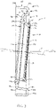
- FIG. 1 is an axial cross-sectional view of a first, inwardly-sealing construction of a seal assembly in accordance with the present invention, shown installed about a shaft and within a housing;
- FIG. 2 is an enlarged view of an upper portion of FIG. 1 ;
- FIG. 3 is an axial cross-sectional view of the first construction seal assembly
- FIG. 4 is an axial cross-sectional view of a combined case and coupler of the first construction seal assembly
- FIG. 5 is an axial cross-sectional view of a second, outwardly-sealing construction of the seal assembly, shown installed about a shaft and within a housing;
- FIG. 6 is an axial cross-sectional view of a combined case and coupler of the second construction seal assembly
- FIG. 7 is an axial cross-sectional view of a third construction of the seal assembly, shown installed about a shaft and within a housing;
- FIG. 8 is an enlarged view of an upper portion of FIG. 5 ;
- FIG. 9 is an axial cross-sectional view of a coupler of the third construction seal assembly.
- FIG. 10 is an axial cross-sectional view of a fourth, inwardly-sealing construction of the seal assembly, shown installed about a shaft and within a housing;
- FIG. 11 is an axial cross-sectional view of the seal member of the fourth construction seal assembly.
- FIG. 12 is an axial cross-sectional view of a fifth construction of the seal assembly, shown installed about a shaft and within a housing.
- FIGS. 1-12 a seal assembly 10 for sealing an annular space between a shaft 1 and a housing 2 .
- the shaft 1 has an outer circumferential surface 1 a and the housing 2 has an inner circumferential surface 2 a defining a bore 3 .
- Either the shaft 1 is rotatable within the housing 2 about a central axis A C extending through the rotatable shaft 1 or the housing 2 is rotatable about the central axis A C extending through a fixed shaft 1 .
- the seal assembly 10 comprises an annular case 12 with a centerline 13 and an annular seal member 14 coupled with the case 12 and having a circular sealing surface 15 with a centerline CL S .
- the sealing surface 15 is engageable with the shaft outer surface 1 a or with the housing inner surface 2 a such that the centerline CL S of the sealing surface 15 is angled or skew with respect to the central axis A C when the seal assembly 10 is installed about the shaft 1 ; i.e., the centerline CL S is not coaxial with or parallel to the axis A C .
- the seal member 14 is preferably “fixed” on or to a non-rotatable housing 2 or shaft 1 and seals against a rotating member 1 or 2 , but may also be fixed on/to a rotatable shaft 1 or housing 2 and seal against a fixed house 2 or shaft 1 , respectively.
- the seal assembly 10 includes a means or device 16 for positioning a generally conventional annular seal member 14 such that the centerline CL S intersects or is skew with respect to the central axis A C , preferably a coupler 18 as described below.
- the seal assembly 10 is formed with a generally standard case 12 and the seal member 14 includes an annular body 60 having an angled outer end 60 a providing the circular sealing surface 15 , which is oriented with the surface centerline CL S angled/skew with respect to the central axis A C .
- the centerline CL S of the sealing surface 15 defines an angle ⁇ S with respect to the central axis A C , the angle ⁇ S having a value of at least one degree (1°) and preferably between two and a half degrees (2.5°) and five degrees (5°) or even greater (e.g., >5°), for reasons described below.
- the case 12 is formed of a rigid material, preferably a metallic material (e.g., aluminum, low carbon steel, etc.) but may be formed of a rigid polymer, a ceramic, etc., and is coupleable with the housing 2 , either directly or through the coupler 18 or another intermediate component (none shown), or is mounted on the shaft 1 .
- the case 12 has a centerline 13 and includes an axial portion 20 with opposing axial ends 20 a , 20 b and a radial flange 22 extending from the axial portion 20 .
- the annular seal member 14 is preferably formed of an elastomeric material, such as natural or synthetic rubber, a thermoplastic, etc., and is connected with the case flange 22 .
- the seal member 14 either has a circular, inner circumferential surface 17 , as depicted in FIGS. 1-4 and 7-12 , or a circular outer circumferential surface 19 , as shown in FIGS. 5 and 6 , each surface 17 , 19 being centered about the centerline CL S and providing the sealing surface 15 .
- the sealing surface 15 is sealingly engageable with the shaft outer surface 1 a (or the outer surface of a component, e.g., a sleeve, disposed about the shaft 1 ) or with the housing inner surface 2 a (or the inner surface of a component disposed within the housing bore 3 ), as described in detail below.
- the annular seal member 14 is formed as a radial lip seal having a “cantilever” body 24 with a fixed inner axial end 24 a connected with the case 12 , an opposing, free outer axial end 24 b , and a wedge-shaped section 24 c adjacent to the free end 24 b providing the sealing surface 15 .
- the wedge-shaped section 24 c of the seal body 24 includes an annular lip 26 , on which is formed the sealing surface 15 and having a front face 27 A and an opposing rear face 27 B.
- the front and rear faces 27 A, 27 B intersect at the sealing surface 15 so as to establish front and rear contact angles ⁇ F , ⁇ R , respectively, between each face 27 A, 27 B and the shaft 1 or housing 2 , as indicated in FIG. 2 .
- the seal assembly 10 is utilized such that the front face 27 A is located on a higher pressure or “oil side” OS of the seal assembly 10 and a rear face 27 B located on a lower pressure or “air side” AS of the assembly 10 .
- the cantilever body 24 preferably also includes an annular groove 25 and a garter spring 29 is disposed within the groove 25 and configured to bias the seal body 24 radially-inwardly ( FIGS.
- seal member 14 may be formed or/and employed in any other appropriate manner.
- the sealing surface 15 engages the shaft outer surface 1 a or the housing inner surface 2 a so as to define a generally elliptical sealing interface SI extending circumferentially about the central axis A C , as shown in FIGS. 1, 5, 7, 10 and 12 .
- the sealing interface SI has two axial end points P 1 , P 2 spaced circumferentially apart about the central axis A C by about one hundred eighty degrees (180°) and axially apart by an axial distance D A along the central axis A C .
- the two end points P 1 , P 2 axially bound a contact band BC of the shaft outer surface 1 a having a width equal to the axial distance D A , the width of the contact band BC preferably being at least one millimeter (1 mm) and most preferably at least four millimeters (4 mm).
- the shaft surface contacted by a seal lip is a narrow circular band directly under the compressed lip, typically with a width of between about one tenth millimeter (0.1 mm) and about five tenths of a millimeter (0.5 mm), the entirety of which remains constantly engaged by the lip during rotation of the shaft.
- 0.1 mm tenth millimeter
- 0.5 mm millimeter
- the seal member 14 is oriented such that one of the two axial end points P 1 , P 2 of the sealing interface SI is a “front” end point P 1 , at which the seal front face 27 A is located furthest into the oil side OS, and the other one of the two axial end points P 1 , P 2 is a “rear” end point P 2 , at which the seal front face 27 A is located at a lesser distance into (or greater distance from) the oil side OS.
- the sealing lip 26 engages the shaft 1 or the housing 2 with a contact pressure which varies between a greatest value at one of the two axial end points P 1 or P 2 , preferably the front end point P 1 , and a least value at the other one of the two axial end points P 2 , P 1 , preferably the rear end point P 2 , due to a distortion of the contact angles ⁇ F , ⁇ R between the seal faces 27 A, 27 B and the shaft 1 or the housing 2 .
- the inclined seal member 14 provides a “pumping effect” to assist in preventing fluid on the oil side OS of the seal assembly 10 from leaking past the seal lip 26 , due to “pushing” the fluid away from the lip 26 , and in certain applications, to circulate fluid back towards a device being lubricated, such as a bearing.
- the seal member 14 is formed with a generally conventional circular cylindrical body having a body centerline CL B that is coaxial with the sealing surface centerline CL S
- the seal assembly 10 further comprises a coupler 18 .
- the coupler 18 is configured to connect the seal member 14 with the case 12 , or to connect the case 12 with the housing 1 , such that the seal member 14 is positioned with both the centerline CL B of the seal member 14 and the centerline CL S of the sealing surface 15 intersecting or skew with respect to the central axis A C when the seal assembly 10 is installed about the shaft 1 .
- the coupler 18 may be integrally formed with the case 12 or may be provided by a discrete component attached to the case 12 , as described in detail below.
- the case 12 is coupled with the housing 2 and the seal member 14 is configured to seal radially inwardly against the shaft outer surface 1 a .
- the case axial portion 20 is disposed against the housing inner surface 2 a and the coupler 18 is formed as the radial flange 22 integral with the axial portion 20 and includes an outer radial portion 30 , a central axial portion 32 and an inner radial portion 34 .
- the outer radial portion 30 extends inwardly from an axial end 20 a of the case axial portion 20 and has outer radial end 30 a and an inner radial end 30 b .
- the central axial portion 32 of the flange 22 has a first end 32 a integrally formed with the inner end 30 b of the outer radial portion 30 and an opposing second axial end 32 b , and extends axially inwardly toward an opposing end 20 b of the case axial portion 20 .
- the flange inner radial portion 34 extends inwardly from the second axial end 32 b of the central axial portion 32 and has an outer radial end 34 a and an inner end 34 b defining a circular bore 35 with a centerline 37 , as shown in FIG. 4 .
- the inner end 24 a of the seal member body 24 is coupled with the inner radial portion 34 of the flange 22 , and is preferably molded thereto.
- the central axial portion 32 of the flange 22 has an axial length L F defined between the first and second ends 32 a , 32 b .
- the axial length L F of the flange axial portion 32 varies from a greatest value L FG at a first angular position F 1 about a centerline 13 of the case 12 to a least value L FL at a second angular position F 2 about the case centerline 13 spaced about one hundred eighty degrees (180°) from the first position F 1 .
- the inner radial portion 34 of the flange 22 and the inner end 24 a of the seal body 24 are each disposed within an angled plane AP 1 , the central axis A C extending non-perpendicularly to the angled plane AP 1 when the seal assembly 10 is disposed about the shaft 1 .
- the structure of the central axial portion 32 having a varying axial length L F and the angled inner radial portion 34 of the case flange 22 provides an integral coupler 18 that positions the seal member 14 in the desired angular orientation described in detail above.
- the case 12 is disposeable upon the shaft 1 and the seal member 14 is configured to seal radially outwardly against the housing inner surface 2 a .
- a seal assembly 10 is particularly suited for a wheel end assembly in which the housing 2 is a rotatable outer hub (not depicted) and the shaft 1 is fixed with respect to the central axis A C .
- the case axial portion 20 has an inner circumferential surface 21 B defining a central bore 23 which receives the shaft 1 and the coupler 18 is again formed as the radial flange 22 integral with the axial portion 20 of the case 12 .
- the radial flange 22 includes an inner radial portion 40 , a central axial portion 42 and an outer radial portion 44 .
- the inner radial portion 40 extends outwardly from an axial end 20 a of the case axial portion 20 and has an inner radial end 40 a and an outer radial end 40 b .
- the central axial portion 42 of the flange 22 has a first axial end 42 a integrally formed with the outer end 40 b of the inner radial portion 40 and an opposing, second axial end 42 b , extends axially toward the opposing end 20 b of the case axial portion 20 and has a varying length L F , as discussed below.
- the flange outer radial portion 44 is generally S-shaped and extends outwardly from the second axial end 42 a of the central axial portion 42 so as to be angled with respect to the case axis 13 , and has an inner radial end 44 a and an outer end 44 b .
- the flange outer radial portion 44 has a first radial section 45 a extending radially from the central axial portion 42 and providing the inner end 44 a , an axial section 45 b and a second radial section 45 c extending outwardly from the central section 45 b and providing the outer end 44 b .
- the inner axial end 24 a of the seal member body 24 is coupled with the outer radial portion 44 of the flange 22 , and is preferably molded thereto.
- the central axial portion 42 of the flange 22 has an axial length L F defined between the first and second ends 42 a , 42 b .
- the axial length L F of the flange axial portion 42 varies from a greatest value L FG at a first angular position F 1 about the centerline 13 of the case 12 to a least value L FL at a second angular position F 2 about the case centerline 13 spaced about one hundred eighty degrees (180°) from the first position F 1 .
- the second radial section 45 c of the outer radial portion 44 of the flange 22 and the inner end 24 a of the seal body 24 are each disposed within an angled plane AP 2 , the central axis A C extending non-perpendicularly to the angled plane AP 2 when the seal assembly 10 is disposed about the shaft 1 .
- the structure of the central axial portion 42 having a varying axial length L F and the angled outer radial portion 44 of the case flange 22 provides an integral coupler 18 that positions the seal member 14 in the desired angular orientation described in detail above.
- the coupler 18 is formed as a separate component configured to couple the case 12 with the housing 2 and to position the seal member 14 in the angled orientation as described above.
- the coupler 18 includes an annular body 50 having a centerline 51 , which is collinear with the central axis A C when the seal assembly 10 is installed about the shaft 1 , a circular cylindrical outer circumferential surface 52 A and a circular cylindrical inner surface 52 B.
- the outer circumferential surface 52 A of the coupler 18 is engageable with the housing inner surface 2 a , preferably frictionally to axially retain the coupler 18 and the seal assembly 10 within the housing 2 , and is centered about the body centerline 51 .
- the inner circumferential surface 52 B of the coupler 18 defines a circular bore 54 and is centered about an axis 55 intersecting or skew with respect to the body centerline 51 .
- the coupler 18 is configured to position the case 12 and the seal member 14 such that the centerline CL S of the sealing surface 15 is collinear with the coupler bore axis 55 .
- the sealing surface centerline CL S is thereby also intersecting or skew with respect to the coupler body centerline 51 , and thus also the central axis A C when the seal assembly 10 is installed about the shaft 1 .
- the annular body 50 of the third construction coupler 18 includes a radially outer cylindrical portion 56 and a radially inner cylindrical portion 58 disposed within and connected with the outer cylindrical portion 56 .
- the outer cylindrical portion 56 has opposing axial ends 56 a , 56 b and an outer surface 56 c providing the coupler outer surface 52 A.
- Each axial end 56 a , 56 b of the outer portion 56 has a radial end surface 57 A, 57 B, respectively, disposed within a separate plane OCP 1 , OCP 2 , respectively.
- the two end surfaces 57 A, 57 B are substantially parallel to each other and the body centerline 51 extends at least substantially perpendicular to each of the two planes OCP 1 and OCP 2 .
- the inner cylindrical portion 58 is preferably integrally formed with the outer cylindrical portion 56 and has opposing axial ends 58 a , 58 b and an inner circumferential surface 48 c providing the coupler inner circumferential surface 52 B and the bore 54 .
- Each axial end 58 a , 58 b of the inner portion 58 has a radial end surface 59 A, 59 B, respectively, disposed within a separate plane ICP 1 , ICP 2 , respectively.
- the two end surfaces 59 A, 59 B of the body inner portion 58 are parallel to each other and the body centerline 51 extends non-perpendicularly to each one of the two planes ICP 1 , ICP 2 , such that the end surfaces 59 A, 59 B are each tilted or angled with respect to the end surfaces 57 A, 57 B of the body outer portion 56 .
- assembly of the seal case 12 (and attached seal member 14 ) into the coupler bore 54 is accomplished by positioning one axial end 20 a or 20 b of the case axial portion 20 aligned with one of the end surfaces 59 B or 59 A, respectively, of the coupler inner portion 58 . Then, the case 12 is inserted into the bore 54 such that the circular outer circumferential surface 21 of the case 12 slides against the circular inner circumferential surface 52 B of the coupler body 50 and is displaced along the bore axis 55 until fully disposed therein.
- the centerline CL S of the sealing surface 15 is at least parallel to and preferably collinear with the bore axis 55 , such that the sealing surface 15 and the seal member 14 are oriented in the desired angular relationship to the central axis A C as described above.
- the annular body 50 may alternatively be formed in any other appropriate manner that provides an outer circumferential surface 52 A engageable with the housing inner surface 2 a and centered about the central axis A C and an inner circumferential surface 52 B engageable with a seal case 12 and centered about an axis 55 intersecting or skew with respect to the central axis A C .
- the separate coupler 18 may be formed as generally annular inner body (not shown) having a cylindrical inner circumferential surface disposeable about the shaft 1 and an angled outer circumferential surface for receiving a standard inner case member with a standard, outwardly-sealing circular lip engageable with the housing inner surface 2 a so as to form the elliptical sealing interface SI.
- the seal assembly 10 is formed without any coupler or means to position a generally standard seal member 14 in the desired angled orientation, but rather includes a seal member 14 with a “non-conventional” cantilever annular body 60 having an angled outer end 60 a with an angled circular lip 62 providing the sealing surface 15 , as discussed above.
- the case 12 includes the axial portion 20 with opposing axial ends 20 a , 20 b and the radial flange 22 extends radially inwardly (as depicted) or outwardly from the axial portion 20 .
- the radial flange 22 is circumferentially uniform or symmetrical about the case centerline 13 and includes the inner end 22 a for receiving the seal member 14 .
- the seal member annular body 60 has a centerline 61 and includes an inner axial end 60 b connected with the inner end 22 a of the case flange portion 22 , the opposing outer end 60 a providing the sealing surface 15 , and a central portion 60 c .
- the body inner axial end 60 b is circular and is disposed in a plane (not indicated) that is substantially perpendicular to any plane containing the body centerline 61 , and thus also the central axis A C when installed on the shaft 1 .
- the body central portion 60 c extends axially between the inner end 60 b and the outer end 60 a and has an axial length BL, which varies from a greatest value BL G at a first angular position PA 1 about the body centerline 61 to a least value BL L at a second angular position PA 2 about the centerline spaced one hundred eighty degrees (180°) from the first angular position PA 1 .
- the outer end 60 a is positioned in an angled orientation, such that the circular sealing lip 62 , and thus the sealing surface 15 , are disposed within an angled plane AP 3 and the sealing surface 15 has a centerline CL S perpendicular to the plane AP 3 .
- the body centerline 61 extends non-perpendicularly to the angled plane AP 3 , such that the central axis A C is likewise non-perpendicular to the plane AP 3 when the seal assembly 10 is disposed about the shaft 1 .
- the sealing surface 15 is located in the angled orientation, i.e., the sealing surface centerline CL S is skew or intersecting the central axis A C , that provides the elliptical sealing interface SI when engaged with the shaft outer surface 1 a (as depicted) or the housing inner surface 2 a (not shown) as described in detail above.
- a coupler 18 is a preferred means 16 for positioning the seal member 14 with respect to the central axis A C as described above
- another possible structure or device for angling the seal member 14 is providing an angled bore 70 in the housing 2 .
- the angled bore 70 is defined by an inner circumferential surface 72 and has a centerline 74 that is angled, i.e., skew or intersecting, with respect to the central axis A C of any shaft 1 installed therein.
- the installation of any generally conventional seal assembly 10 within the bore 70 will position the seal member 14 in the angled orientation as described in detail above.
Landscapes
- Engineering & Computer Science (AREA)
- General Engineering & Computer Science (AREA)
- Mechanical Engineering (AREA)
- Sealing Devices (AREA)
- Sealing With Elastic Sealing Lips (AREA)
Abstract
Description
Claims (17)
Priority Applications (3)
| Application Number | Priority Date | Filing Date | Title |
|---|---|---|---|
| US16/878,971 US11391375B2 (en) | 2020-05-20 | 2020-05-20 | Angled radial lip seal assembly |
| CN202110243743.1A CN113719613A (en) | 2020-05-20 | 2021-03-05 | Inclined radial lip seal assembly |
| DE102021204783.1A DE102021204783A1 (en) | 2020-05-20 | 2021-05-11 | Angular radial lip seal arrangement |
Applications Claiming Priority (1)
| Application Number | Priority Date | Filing Date | Title |
|---|---|---|---|
| US16/878,971 US11391375B2 (en) | 2020-05-20 | 2020-05-20 | Angled radial lip seal assembly |
Publications (2)
| Publication Number | Publication Date |
|---|---|
| US20210364088A1 US20210364088A1 (en) | 2021-11-25 |
| US11391375B2 true US11391375B2 (en) | 2022-07-19 |
Family
ID=78408731
Family Applications (1)
| Application Number | Title | Priority Date | Filing Date |
|---|---|---|---|
| US16/878,971 Active 2040-06-27 US11391375B2 (en) | 2020-05-20 | 2020-05-20 | Angled radial lip seal assembly |
Country Status (3)
| Country | Link |
|---|---|
| US (1) | US11391375B2 (en) |
| CN (1) | CN113719613A (en) |
| DE (1) | DE102021204783A1 (en) |
Families Citing this family (1)
| Publication number | Priority date | Publication date | Assignee | Title |
|---|---|---|---|---|
| US12110966B2 (en) * | 2023-02-14 | 2024-10-08 | Aktiebolaget Skf | Self-retaining lip seal |
Citations (5)
| Publication number | Priority date | Publication date | Assignee | Title |
|---|---|---|---|---|
| US3929340A (en) | 1972-04-24 | 1975-12-30 | Chicago Rawhide Mfg Co | Seal with pumping action |
| US4739998A (en) * | 1986-11-21 | 1988-04-26 | Federal-Mogul Corporation | Bidirectional seal with elliptical sealing barriers |
| US8328201B2 (en) * | 2010-06-23 | 2012-12-11 | Aktiebolaget Skf | Pumping seal assembly with angled spring |
| US8720903B2 (en) | 2010-05-18 | 2014-05-13 | Aktiebolaget Skf | Fluid seal assembly |
| US9228658B2 (en) * | 2011-12-21 | 2016-01-05 | Aktiebolaget Skf | Pumping seal with aligned spring |
Family Cites Families (2)
| Publication number | Priority date | Publication date | Assignee | Title |
|---|---|---|---|---|
| US7419165B2 (en) * | 2004-08-18 | 2008-09-02 | Federal-Mogul World Wide, Inc. | Seal assembly and method of manufacturing the same |
| DE102014115985A1 (en) * | 2014-11-03 | 2016-05-19 | Karl Storz Gmbh & Co. Kg | Sealing device for sealing a passage for a medical instrument |
-
2020
- 2020-05-20 US US16/878,971 patent/US11391375B2/en active Active
-
2021
- 2021-03-05 CN CN202110243743.1A patent/CN113719613A/en active Pending
- 2021-05-11 DE DE102021204783.1A patent/DE102021204783A1/en active Pending
Patent Citations (5)
| Publication number | Priority date | Publication date | Assignee | Title |
|---|---|---|---|---|
| US3929340A (en) | 1972-04-24 | 1975-12-30 | Chicago Rawhide Mfg Co | Seal with pumping action |
| US4739998A (en) * | 1986-11-21 | 1988-04-26 | Federal-Mogul Corporation | Bidirectional seal with elliptical sealing barriers |
| US8720903B2 (en) | 2010-05-18 | 2014-05-13 | Aktiebolaget Skf | Fluid seal assembly |
| US8328201B2 (en) * | 2010-06-23 | 2012-12-11 | Aktiebolaget Skf | Pumping seal assembly with angled spring |
| US9228658B2 (en) * | 2011-12-21 | 2016-01-05 | Aktiebolaget Skf | Pumping seal with aligned spring |
Also Published As
| Publication number | Publication date |
|---|---|
| US20210364088A1 (en) | 2021-11-25 |
| CN113719613A (en) | 2021-11-30 |
| DE102021204783A1 (en) | 2021-11-25 |
Similar Documents
| Publication | Publication Date | Title |
|---|---|---|
| US6109617A (en) | Gas seal assembly and method of sealing | |
| US10267422B2 (en) | Sealing device | |
| US8534674B2 (en) | Unitized radial fluid seal | |
| CN104220769B (en) | Rotary chuck seal with internal face sealing surface | |
| US10550941B2 (en) | Radial fluid seal | |
| US20070201782A1 (en) | Seal device and rolling bearing unit with seal device | |
| JP2013130296A (en) | Sealing device | |
| US9995396B1 (en) | Outwardly sealing pumping seal assembly | |
| US6186510B1 (en) | Mechanical contact bearing seal | |
| US8955849B2 (en) | Radial shaft seal and assembly therewith | |
| CN102439324A (en) | Bearing seal assemblies especially for agricultural applications | |
| US5039112A (en) | Multi-layer lip seal assembly | |
| US20190107204A1 (en) | Seal Assembly with Eccentricity Tracking | |
| US11391375B2 (en) | Angled radial lip seal assembly | |
| US10697546B2 (en) | Dynamic seal | |
| US8328201B2 (en) | Pumping seal assembly with angled spring | |
| CN114151545A (en) | Cassette seal for use in extreme environments | |
| US20130223782A1 (en) | Mechanical face seal assembly for bearings | |
| US20220307604A1 (en) | Seal assembly with labyrinth channel | |
| CN115614393A (en) | Sealing assembly for a truck hub with radial labyrinth | |
| US11761541B2 (en) | Unitized seal assembly with axial positioner | |
| CN115614392A (en) | Low friction seal assemblies for truck hubs | |
| JP3138507U (en) | Sealing device | |
| US20250257799A1 (en) | Radial shaft seal arrangement | |
| US20230250878A1 (en) | Seal assembly with deflectable coupler for centering a sealing member |
Legal Events
| Date | Code | Title | Description |
|---|---|---|---|
| FEPP | Fee payment procedure |
Free format text: ENTITY STATUS SET TO UNDISCOUNTED (ORIGINAL EVENT CODE: BIG.); ENTITY STATUS OF PATENT OWNER: LARGE ENTITY |
|
| AS | Assignment |
Owner name: AKTIEBOLAGET SKF, SWEDEN Free format text: ASSIGNMENT OF ASSIGNORS INTEREST;ASSIGNORS:PECAK, ROBERT D.;LEVY, DANIEL J.;REEL/FRAME:053034/0826 Effective date: 20200623 |
|
| STPP | Information on status: patent application and granting procedure in general |
Free format text: RESPONSE TO NON-FINAL OFFICE ACTION ENTERED AND FORWARDED TO EXAMINER |
|
| STPP | Information on status: patent application and granting procedure in general |
Free format text: NON FINAL ACTION MAILED |
|
| STPP | Information on status: patent application and granting procedure in general |
Free format text: RESPONSE TO NON-FINAL OFFICE ACTION ENTERED AND FORWARDED TO EXAMINER |
|
| STPP | Information on status: patent application and granting procedure in general |
Free format text: NOTICE OF ALLOWANCE MAILED -- APPLICATION RECEIVED IN OFFICE OF PUBLICATIONS |
|
| STPP | Information on status: patent application and granting procedure in general |
Free format text: PUBLICATIONS -- ISSUE FEE PAYMENT VERIFIED |
|
| STCF | Information on status: patent grant |
Free format text: PATENTED CASE |
|
| MAFP | Maintenance fee payment |
Free format text: PAYMENT OF MAINTENANCE FEE, 4TH YEAR, LARGE ENTITY (ORIGINAL EVENT CODE: M1551); ENTITY STATUS OF PATENT OWNER: LARGE ENTITY Year of fee payment: 4 |