US11381453B2 - Method and system for service software upgrade in an evolved packet core (EPC) system - Google Patents
Method and system for service software upgrade in an evolved packet core (EPC) system Download PDFInfo
- Publication number
- US11381453B2 US11381453B2 US16/927,866 US202016927866A US11381453B2 US 11381453 B2 US11381453 B2 US 11381453B2 US 202016927866 A US202016927866 A US 202016927866A US 11381453 B2 US11381453 B2 US 11381453B2
- Authority
- US
- United States
- Prior art keywords
- service
- service server
- server
- data flow
- version
- Prior art date
- Legal status (The legal status is an assumption and is not a legal conclusion. Google has not performed a legal analysis and makes no representation as to the accuracy of the status listed.)
- Active, expires
Links
Images


Classifications
-
- H—ELECTRICITY
- H04—ELECTRIC COMMUNICATION TECHNIQUE
- H04L—TRANSMISSION OF DIGITAL INFORMATION, e.g. TELEGRAPHIC COMMUNICATION
- H04L41/00—Arrangements for maintenance, administration or management of data switching networks, e.g. of packet switching networks
- H04L41/08—Configuration management of networks or network elements
- H04L41/0803—Configuration setting
- H04L41/0813—Configuration setting characterised by the conditions triggering a change of settings
- H04L41/082—Configuration setting characterised by the conditions triggering a change of settings the condition being updates or upgrades of network functionality
-
- G—PHYSICS
- G06—COMPUTING OR CALCULATING; COUNTING
- G06F—ELECTRIC DIGITAL DATA PROCESSING
- G06F8/00—Arrangements for software engineering
- G06F8/60—Software deployment
- G06F8/65—Updates
-
- G—PHYSICS
- G06—COMPUTING OR CALCULATING; COUNTING
- G06F—ELECTRIC DIGITAL DATA PROCESSING
- G06F9/00—Arrangements for program control, e.g. control units
- G06F9/06—Arrangements for program control, e.g. control units using stored programs, i.e. using an internal store of processing equipment to receive or retain programs
- G06F9/44—Arrangements for executing specific programs
- G06F9/445—Program loading or initiating
-
- H—ELECTRICITY
- H04—ELECTRIC COMMUNICATION TECHNIQUE
- H04L—TRANSMISSION OF DIGITAL INFORMATION, e.g. TELEGRAPHIC COMMUNICATION
- H04L63/00—Network architectures or network communication protocols for network security
- H04L63/14—Network architectures or network communication protocols for network security for detecting or protecting against malicious traffic
- H04L63/1433—Vulnerability analysis
-
- H—ELECTRICITY
- H04—ELECTRIC COMMUNICATION TECHNIQUE
- H04L—TRANSMISSION OF DIGITAL INFORMATION, e.g. TELEGRAPHIC COMMUNICATION
- H04L63/00—Network architectures or network communication protocols for network security
- H04L63/14—Network architectures or network communication protocols for network security for detecting or protecting against malicious traffic
- H04L63/1441—Countermeasures against malicious traffic
-
- H—ELECTRICITY
- H04—ELECTRIC COMMUNICATION TECHNIQUE
- H04L—TRANSMISSION OF DIGITAL INFORMATION, e.g. TELEGRAPHIC COMMUNICATION
- H04L65/00—Network arrangements, protocols or services for supporting real-time applications in data packet communication
- H04L65/10—Architectures or entities
- H04L65/1016—IP multimedia subsystem [IMS]
-
- H—ELECTRICITY
- H04—ELECTRIC COMMUNICATION TECHNIQUE
- H04L—TRANSMISSION OF DIGITAL INFORMATION, e.g. TELEGRAPHIC COMMUNICATION
- H04L67/00—Network arrangements or protocols for supporting network services or applications
- H04L67/34—Network arrangements or protocols for supporting network services or applications involving the movement of software or configuration parameters
-
- H—ELECTRICITY
- H04—ELECTRIC COMMUNICATION TECHNIQUE
- H04W—WIRELESS COMMUNICATION NETWORKS
- H04W28/00—Network traffic management; Network resource management
- H04W28/02—Traffic management, e.g. flow control or congestion control
- H04W28/0215—Traffic management, e.g. flow control or congestion control based on user or device properties, e.g. MTC-capable devices
-
- H04W72/042—
-
- H—ELECTRICITY
- H04—ELECTRIC COMMUNICATION TECHNIQUE
- H04W—WIRELESS COMMUNICATION NETWORKS
- H04W72/00—Local resource management
- H04W72/20—Control channels or signalling for resource management
- H04W72/23—Control channels or signalling for resource management in the downlink direction of a wireless link, i.e. towards a terminal
-
- H—ELECTRICITY
- H04—ELECTRIC COMMUNICATION TECHNIQUE
- H04W—WIRELESS COMMUNICATION NETWORKS
- H04W8/00—Network data management
- H04W8/18—Processing of user or subscriber data, e.g. subscribed services, user preferences or user profiles; Transfer of user or subscriber data
- H04W8/183—Processing at user equipment or user record carrier
-
- H—ELECTRICITY
- H04—ELECTRIC COMMUNICATION TECHNIQUE
- H04L—TRANSMISSION OF DIGITAL INFORMATION, e.g. TELEGRAPHIC COMMUNICATION
- H04L41/00—Arrangements for maintenance, administration or management of data switching networks, e.g. of packet switching networks
- H04L41/08—Configuration management of networks or network elements
- H04L41/085—Retrieval of network configuration; Tracking network configuration history
- H04L41/0859—Retrieval of network configuration; Tracking network configuration history by keeping history of different configuration generations or by rolling back to previous configuration versions
- H04L41/0863—Retrieval of network configuration; Tracking network configuration history by keeping history of different configuration generations or by rolling back to previous configuration versions by rolling back to previous configuration versions
-
- H—ELECTRICITY
- H04—ELECTRIC COMMUNICATION TECHNIQUE
- H04L—TRANSMISSION OF DIGITAL INFORMATION, e.g. TELEGRAPHIC COMMUNICATION
- H04L47/00—Traffic control in data switching networks
- H04L47/10—Flow control; Congestion control
- H04L47/24—Traffic characterised by specific attributes, e.g. priority or QoS
- H04L47/2483—Traffic characterised by specific attributes, e.g. priority or QoS involving identification of individual flows
-
- H—ELECTRICITY
- H04—ELECTRIC COMMUNICATION TECHNIQUE
- H04W—WIRELESS COMMUNICATION NETWORKS
- H04W12/00—Security arrangements; Authentication; Protecting privacy or anonymity
- H04W12/30—Security of mobile devices; Security of mobile applications
- H04W12/37—Managing security policies for mobile devices or for controlling mobile applications
Definitions
- aspects of this application relate to the field of communications technologies, and in particular, to a software upgrade method and a system.
- An evolved packet core (EPC) system in a long term evolution (Long Term Evolution, LTE) architecture includes a plurality of types of network elements.
- the network elements communicate with each other by using an interface protocol, and mainly provide functions of processing and exchanging mobile voice and data.
- each network element is usually deployed as a plurality of service servers installed with the same service software, and a traffic decider is disposed. In this way, the traffic decider may determine a specific service server to which a service is to be forwarded for processing.
- a system manager in the EPC system controls all service servers to be disconnected from all user equipments, and then controls each service server to upgrade installed service software from a first version to a second version. After the service software in all the service servers is successfully upgraded, the traffic decider receives a service request sent by user equipment, and forwards the service request to an upgraded service server.
- the service software of the second version cannot be verified by using service data on an existing network. Therefore, a potential vulnerability in the service software of the second version can be exposed only after the service software gets online, causing interruption of all services. In addition, after a service is interrupted, the service software in the service server further needs to be rolled back from the second version to the first version, and interruption of all services is also caused in the rollback process.
- aspects of this application provide a software upgrade method and a system.
- a software upgrade method is provided.
- the method is applied to an EPC system, the EPC system includes a system manager, a traffic decider, a first service server, and a second service server, and the first service server and the second service server are installed with service software of a first version.
- the method includes: controlling, by the system manager, the second service server to upgrade the installed service software from the first version to a second version, controlling the traffic decider to set a service flow identifier included in a service data flow on the first service server to indicate the second service server, and controlling the first service server to transfer, to the second service server, the service data flow that includes the service flow identifier and that is on the first service server; receiving, by the traffic decider, a service data flow sent by user equipment, and forwarding the service data flow to the second service server based on a service flow identifier in the service data flow; and after the second service server becomes stable, controlling, by the system manager, the first service server to upgrade the installed service software from the first version to the second version.
- the service software installed in the second service server that serves a small quantity of users is upgraded.
- the service software installed in the second service server that serves a small quantity of users is upgraded.
- only services of the small quantity of users served by the upgraded second service server are interrupted, and services on the first service server that serves a large quantity of users are still run normally on the first service server.
- This can avoid a problem that all services are interrupted when a potential vulnerability is exposed after service software installed in all service servers is upgraded, and can also avoid a problem that all services are interrupted during a rollback, thereby ensuring service continuity.
- After the upgraded second service server becomes stable remaining first service servers are gradually controlled to upgrade the installed service software. This may also be considered as verifying the service software by using service data on an existing network, thereby ensuring stability of the EPC system.
- a service data flow on the first service server is transferred to the upgraded second service server, instead of disconnecting the EPC system from the user equipments and reconnecting the user equipments to the EPC system. This can ensure service continuity and improve user experience.
- a service flow identifier is used to indicate whether a service data flow is to be forwarded to the first service server or the upgraded second service server. This can avoid a problem of high signaling overheads caused when new signaling is specially set to transmit the service flow identifier, thereby reducing signaling overheads.
- the method further includes: receiving, by the traffic decider, a service request sent by user equipment, and forwarding the service request to the second service server; allocating, by the second service server, a service flow identifier for the service request from the user equipment; and receiving, by the traffic decider, a service data flow sent by the user equipment, and forwarding the service data flow to the second service server based on the service flow identifier in the service data flow.
- a service request sent by user equipment that is connected to the EPC system for the first time is forwarded to the upgraded second service server. This can avoid a problem that if the service request is forwarded to the first service server, a service data flow sent by the user equipment needs to be transferred to the upgraded second service server when the service software installed in the first service server needs to be upgraded subsequently, thereby simplifying a software upgrade scheme.
- a service data flow sent by user equipment that is newly connected to the EPC system is forwarded to the upgraded second service server, and then a service data flow on the first service server is migrated.
- the service data flows are migrated in batches. This can avoid a problem that all services are interrupted when a potential vulnerability is exposed after all service data flows are migrated to the upgraded second service server at a time, and can also avoid a problem that all services are interrupted during a rollback.
- After the upgraded second service server becomes stable, service data flows forwarded to the upgraded second service server for processing are gradually increased, thereby ensuring stability of the EPC system.
- the method further includes: obtaining, by the second service server, a value interval of the allocated service flow identifier, where value intervals of service flow identifiers of service software of different versions are different; and the allocating, by the second service server, a service flow identifier for the service request from the user equipment includes: selecting, by the second service server, a value from the value interval as the service flow identifier.
- the method further includes: obtaining, by the traffic decider, attribute information of the user equipment; and when the attribute information indicates that the user equipment belongs to a preset user group, triggering execution of the step of forwarding the service request to the second service server; and when the attribute information indicates that the user equipment does not belong to a preset user group, forwarding the service request to the first service server.
- the service software of the second version is used for trial among friendly users. In this way, even if a potential vulnerability in the service software of the second version is exposed and causes service interruption, the friendly users do not complain, to ensure credibility of the EPC system.
- the method further includes: after an exception occurs in the second service server, controlling, by the system manager, the second service server to roll back the installed service software from the second version to the first version.
- the second service server migrates a service data flow on the second service server to the first service server, and the system manager controls the second service server to roll back the installed service software from the second version to the first version.
- the system manager controls the second service server to roll back the installed service software from the second version to the first version.
- the service request includes a control-plane service request and a user-plane service request
- the service data flow includes a control-plane service data flow and a user-plane service data flow
- a control plane protocol includes a general packet radio service (GPRS) tunneling protocol-control plane GTP-C, a stream control transmission protocol (SCTP), a proxy mobile internet protocol (IP PMIP), an S1 interface application protocol (S1-AP), and a radio access network application part (RANAP); and a user plane protocol includes a GPRS tunneling protocol-user plane GTP-U or an IP.
- GPRS general packet radio service
- SCTP stream control transmission protocol
- IP PMIP proxy mobile internet protocol
- S1-AP S1 interface application protocol
- RANAP radio access network application part
- a user plane protocol includes a GPRS tunneling protocol-user plane GTP-U or an IP.
- an evolved packet core EPC system includes a system manager, a traffic decider, a first service server, and a second service server, and the first service server and the second service server are installed with service software of a first version.
- the system manager is configured to control the second service server to upgrade the installed service software from the first version to a second version, control the traffic decider to set a service flow identifier included in a service data flow on the first service server to indicate the second service server, and control the first service server to transfer, to the second service server, the service data flow that includes the service flow identifier and that is on the first service server; the traffic decider is further configured to receive a service data flow sent by user equipment, and forward the service data flow to the second service server based on a service flow identifier in the service data flow; and the system manager is further configured to: after the second service server becomes stable, control the first service server to upgrade the installed service software from the first version to the second version.
- the service software installed in the second service server that serves a small quantity of users is upgraded.
- the service software installed in the second service server that serves a small quantity of users is upgraded.
- only services of the small quantity of users served by the upgraded second service server are interrupted, and services on the first service server that serves a large quantity of users are still run normally on the first service server.
- This can avoid a problem that all services are interrupted when a potential vulnerability is exposed after service software installed in all service servers is upgraded, and can also avoid a problem that all services are interrupted during a rollback, thereby ensuring service continuity.
- After the upgraded second service server becomes stable remaining first service servers are gradually controlled to upgrade the installed service software. This may also be considered as verifying the service software by using service data on an existing network, thereby ensuring stability of the EPC system.
- a service data flow on the first service server is transferred to the upgraded second service server, instead of disconnecting the EPC system from the user equipments and reconnecting the user equipments to the EPC system. This can ensure service continuity and improve user experience.
- a service flow identifier is used to indicate whether a service data flow is to be forwarded to the first service server or the upgraded second service server. This can avoid a problem of high signaling overheads caused when new signaling is specially set to transmit a service flow identifier, thereby reducing signaling overheads.
- the traffic decider is further configured to: obtain attribute information of the user equipment; and when the attribute information indicates that the user equipment belongs to a preset user group, trigger execution of the step of forwarding the service request to the second service server; and when the attribute information indicates that the user equipment does not belong to a preset user group, the traffic decider is further configured to forward the service request to the first service server.
- the service software of the second version is used for trial among friendly users. In this way, even if a potential vulnerability in the service software of the second version is exposed and causes service interruption, the friendly users do not complain, to ensure credibility of the EPC system.
- the second service server is further configured to obtain a value interval of the allocated service flow identifier, where value intervals of service flow identifiers of service software of different versions are different; and the second service server is further configured to select a value from the value interval as the service flow identifier.
- the traffic decider is configured to receive a service request sent by user equipment, and forward the service request to the second service server; the second service server is configured to allocate a service flow identifier for the service request from the user equipment; and the traffic decider is further configured to receive a service data flow sent by the user equipment, forward the service data flow to the second service server based on the service flow identifier in the service data flow, and transfer, to the second service server, the service data flow that includes the service flow identifier and that is on the first service server.
- a service request sent by user equipment that is connected to the EPC system for the first time is forwarded to the upgraded second service server. This can avoid a problem that if the service request is forwarded to the first service server, a service data flow sent by the user equipment needs to be transferred to the upgraded second service server when the service software installed in the first service server needs to be upgraded subsequently, thereby simplifying a software upgrade scheme.
- a service data flow sent by user equipment that is newly connected to the EPC system is forwarded to the upgraded second service server, and then a service data flow on the first service server is migrated.
- the service data flows are migrated in batches. This can avoid a problem that all services are interrupted when a potential vulnerability is exposed after all service data flows are migrated to the upgraded second service server at a time, and can also avoid a problem that all services are interrupted during a rollback.
- After the upgraded second service server becomes stable, service data flows forwarded to the upgraded second service server for processing are gradually increased, thereby ensuring stability of the EPC system.
- the second service server is further configured to obtain a value interval of the allocated service flow identifier, where value intervals of service flow identifiers of service software of different versions are different; and the second service server is further configured to select a value from the value interval as the service flow identifier.
- the traffic decider is further configured to: obtain attribute information of the user equipment; and when the attribute information indicates that the user equipment belongs to a preset user group, trigger execution of the step of forwarding the service request to the second service server; and when the attribute information indicates that the user equipment does not belong to a preset user group, forward the service request to the first service server.
- the service software of the second version is used for trial among friendly users. In this way, even if a potential vulnerability in the service software of the second version is exposed and causes service interruption, the friendly users do not complain, to ensure credibility of the EPC system.
- system manager is further configured to: after controlling the second service server to upgrade the installed service software from the first version to the second version, and if an exception occurs in the second service server, control the second service server to roll back the installed service software from the second version to the first version.
- the second service server is further configured to migrate a service data flow on the second service server to the first service server, and the system manager is further configured to control the second service server to roll back the installed service software from the second version to the first version.
- the system manager is further configured to control the second service server to roll back the installed service software from the second version to the first version.
- the service request includes a control-plane service request and a user-plane service request
- the service data flow includes a control-plane service data flow and a user-plane service data flow
- a control plane protocol includes a general packet radio service (GPRS) tunneling protocol-control plane GTP-C, a stream control transmission protocol (SCTP), a proxy mobile internet protocol (IP PMIP), an S1 interface application protocol S1-AP, and a radio access network application part (RANAP); and a user plane protocol includes a GPRS tunneling protocol-user plane protocol GTP-U or an IP.
- GPRS general packet radio service
- SCTP stream control transmission protocol
- IP PMIP proxy mobile internet protocol
- S1-AP S1 interface application protocol
- RANAP radio access network application part
- a user plane protocol includes a GPRS tunneling protocol-user plane protocol GTP-U or an IP.
- FIG. 1 is a schematic structural diagram of an LTE system according to an example embodiment of this application.
- FIG. 2 is a schematic structural diagram of a network element according to an example embodiment of this application.
- FIG. 3 is a schematic diagram of software upgrade in a related technology according to an example embodiment of this application.
- FIG. 4 is a flowchart of a software upgrade method according to an example embodiment of this application.
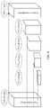
- FIG. 5 is a schematic diagram of distribution of traffic deciders in protocol units according to an example embodiment of this application.
- FIG. 6 is a schematic diagram of a processing path of a service request sent by user equipment according to an example embodiment of this application;
- FIG. 7 is a schematic diagram of a processing path of a service data flow sent by user equipment according to an example embodiment of this application.
- FIG. 8 is a schematic diagram of software upgrade in this application according to an example embodiment of this application.
- FIG. 9 is a structural diagram of a software upgrade apparatus according to an example embodiment of this application.
- a “unit” mentioned in this specification refers to a functional structure obtained through logical division, and the “unit” can be implemented by hardware only or a combination of hardware and software.
- FIG. 1 is a schematic structural diagram of an LTE system 100 according to an example embodiment of this application.
- the LTE system 100 includes user equipment (UE), an evolved UMTS terrestrial radio access network (E-UTRAN), a UMTS terrestrial radio access network UTRAN), a GSM/EDGE radio access network (GERAN), an EPC system, and an internet protocol (IP) service.
- the EPC system includes the following network elements: a mobility management network entity (MME), a serving gateway (S-GW for short), a packet data network gateway entity (P-GW), a policy and charging rules function unit (PCRF), a home subscriber server (HSS), a serving general packet radio service supporting node (SGSN), an equipment identity register (EIR), and a common search space (CSS).
- MME mobility management network entity
- S-GW serving gateway
- P-GW packet data network gateway entity
- PCRF policy and charging rules function unit
- HSS home subscriber server
- SGSN serving general packet radio service supporting node
- EIR equipment identity
- the E-UTRAN is configured to implement a function related to a radio evolved network.
- the MME is responsible for mobility management on a control plane, for example, user context and mobility status management and temporary user identity allocation.
- the S-GW is a user plane anchor between 3rd Generation Partner Project (3GPP) access networks.
- the P-GW is a user plane anchor between a 3GPP access network and a non-3GPP access network and is an interface of an external packet data network (PDN).
- the PCRF is configured to formulate a policy control rule and perform flow-based charging.
- the HSS is configured to store user subscription information.
- UE performs control-plane and user-plane interaction with a System Architecture Evolution (SAE) network through the E-UTRAN.
- SAE System Architecture Evolution
- the UTRAN and the GERAN are configured to implement all radio-related functions in an existing GPRS/UMTS network.
- the SGSN is configured to implement functions such as routing and forwarding, mobility management, session management, and user information storage in the GPRS/UMTS network.
- Control plane protocols include the GPRS tunneling protocol-control plane (GTP-C), the stream control transmission protocol (SCTP), the proxy mobile IP (PMIP), and the S1 interface application protocol (S1-AP), and the radio access network application part (RANAP).
- GTP-C GPRS tunneling protocol-control plane
- SCTP stream control transmission protocol
- PMIP proxy mobile IP
- S1-AP S1 interface application protocol
- RANAP radio access network application part
- a user plane protocol includes the GPRS tunneling protocol-user plane (GTP-U) or the IP.
- each network element in the EPC system can be deployed as a plurality of service servers. All the service servers are installed with the same service software, to provide a same service for user equipment in different areas, thereby implementing distributed deployment.
- a system manager and a traffic decider are further disposed in the EPC system. The system manager is configured to control each network element in the EPC system, and the traffic decider is configured to determine a specific service server to which a service data flow obtained after a service request is sent is forwarded.
- FIG. 2 is a schematic structural diagram of a network element 200 according to another example embodiment of this application.
- the network element 200 includes a processor 220 and a wireless transceiver 240 connected to the processor 220 .
- the wireless transceiver 240 may include one or more antennas, and the antenna enables the network element 200 to send or receive a radio signal.
- the wireless transceiver 240 may be connected to a communications circuit 260 .
- the communications circuit 260 may perform various processing on a signal received by the wireless transceiver 240 or sent by the wireless transceiver 240 , for example, modulate a signal sent by the wireless transceiver 240 and demodulate a signal received by the wireless transceiver 240 .
- the communications circuit 260 may include a radio frequency (radio frequency, RF) chip and a baseband chip.
- the communications circuit 260 may be connected to the processor 220 . Alternatively, the communications circuit 260 may be integrated into the processor 220 .
- the processor 220 is a control center of a network element.
- the processor 220 may be a central processing unit (CPU), a network processor (NP), or a combination of a CPU and an NP.
- the processor 220 may further include a hardware chip.
- the hardware chip may be an application-specific integrated circuit (ASIC), a programmable logic device (PLD), or a combination thereof.
- the PLD may be a complex programmable logic device (CPLD), a field-programmable gate array (FPGA), a generic array logic (GAL), or a combination thereof.
- a memory 280 is connected to the processor 220 by using a bus or in another manner.
- the memory 280 may be a volatile memory, a non-volatile memory, or a combination thereof.
- the volatile memory may be a random-access memory (RAM), for example, a static random access memory (SRAM) or a dynamic random access memory (DRAM).
- the non-volatile memory may be a read-only memory (ROM), for example, a programmable read only memory (PROM), an erasable programmable read only memory (EPROM), or an electrically erasable programmable read-only memory (EEPROM).
- ROM read-only memory
- PROM programmable read only memory
- EPROM erasable programmable read only memory
- EEPROM electrically erasable programmable read-only memory
- the non-volatile memory may alternatively be a flash memory or a magnetic memory, for example, a magnetic tape, a floppy disk, or a hard disk.
- the non-volatile memory may alternatively be a compact disc.
- service data flows sent by all user equipments are all transferred to an upgraded service server at a time, leading to problems that all services are interrupted due to a potential vulnerability in an upgrade process and all services are interrupted due to a rollback.
- service servers are upgraded in batches, and then service data flows sent by user equipments are migrated to an upgraded service server in batches. For details, refer to descriptions in the following embodiments.
- one network element device may include a plurality of service servers, and the service servers may be upgraded in batches according to a proportion.
- service servers of a fixed proportion are upgraded each time, for example, 10%.
- a proportion of service servers in each upgrade is gradually increased.
- a proportion of service servers in a first upgrade is 5%
- a proportion of service servers in a second upgrade is 10%. This is not limited in this embodiment.
- a service server that is upgraded first is referred to as a second service server, and a service server that is upgraded later is referred to as a first service server.
- FIG. 4 is a flowchart of a software upgrade method according to an example embodiment of this application.
- the method is applied to the EPC system shown in FIG. 1 .
- only one first service server and one second service server are used as an example for description.
- the method includes the following several steps.
- Step 401 A system manager controls the second service server to upgrade installed service software from a first version to a second version.
- a version of service software before an upgrade is referred to as the first version
- a version of service software after the upgrade is referred to as the second version.
- the system manager may randomly select one of the two service servers as the second service server, and directly control the second service server to upgrade the installed service software from the first version to the second version.
- the system manager may select a service server in an idle state as the second service server, and control the second service server to upgrade the installed service software from the first version to the second version.
- the service server being in an idle state means that the service server does not process a service data flow or process a small quantity of service data flows.
- the system manager may send an upgrade instruction to the second service server.
- the second service server After receiving the upgrade instruction, the second service server obtains and installs the service software of the second version, and upgrades the service software from the first version to the second version.
- the second service server described below is a second service server whose installed service software is upgraded to the second version.
- Step 402 A traffic decider receives a service request sent by user equipment, and forwards the service request to the second service server.
- the user equipment is user equipment that is connected to the EPC system for the first time.
- the user equipment may be user equipment that gets online again after getting offline. After the user equipment gets offline, a service data flow that is previously sent by the user equipment and that is forwarded by the traffic decider to the first service server is deleted.
- the traffic decider After receiving the service request, the traffic decider parses the service request. When a result of the parsing is new user signaling or an initial service access request, the traffic decider determines that the user equipment is user equipment that is connected to the EPC system for the first time, and sends the service request to the second service server.
- the service request includes a control-plane service request and a user-plane service request. This can avoid a problem that if the service request is forwarded to the first service server, a service data flow sent by the user equipment needs to be transferred to the upgraded second service server when the service software installed in the first service server needs to be upgraded subsequently, thereby simplifying a software upgrade scheme.
- the traffic decider obtains attribute information of the user equipment; and when the attribute information indicates that the user equipment belongs to a preset user group, the traffic decider triggers execution of the step of forwarding the service request to the second service server; and when the attribute information indicates that the user equipment does not belong to a preset user group, the traffic decider forwards the service request to the first service server.
- the preset user group is a friendly user group
- the service software of the second version is used for trial among friendly users. In this way, even if a potential vulnerability in the service software of the second version is exposed and causes service interruption, the friendly users do not complain, to ensure credibility of the EPC system.
- the EPC system includes a logical traffic decider.
- the logical traffic decider may be deployed in a distributed manner.
- the traffic decider is deployed on a load balancer and a protocol unit or in another location.
- a traffic decider is represented by a circular ring in FIG. 5 .
- one traffic decider is disposed on each protocol unit.
- the first service server is corresponding to an old traffic decider
- the second service server is corresponding to a new traffic decider
- each protocol unit is corresponding to one traffic decider
- a DB (old) is a database storing service software of a first version
- a DB (new) is a database storing service software of a second version.
- the traffic decider is a traffic decider
- each service server includes a diameter/SCTP protocol unit and a GTP-C protocol unit. After receiving a service request, the old traffic decider cannot parse the service request, and forwards the service request to a GTP-C protocol unit on the first service server.
- the GTP-C protocol unit learns, by parsing, that the service request is new user signaling or an initial service access request, determines that user equipment is connected to the EPC system for the first time, and forwards the service request to the new traffic decider by using a traffic decider of the GTP-C protocol unit.
- the new traffic decider forwards the service request to a GTP-C protocol unit on the second service server, and the GTP-C protocol unit sends a processing result to the new traffic decider. If there is only one data link, the new traffic decider sends the processing result to the old traffic decider, and the old traffic decider outputs the processing result. If there are a plurality of data links, the new traffic decider may output the processing result through another link.
- the foregoing processing process may be represented by using arrows in FIG. 6 .
- Step 403 The second service server allocates a service flow identifier for the service request from the user equipment.
- the service flow identifier may be carried in a service data flow for transmission. This can avoid a problem of high signaling overheads caused when new signaling is specially set to transmit the service flow identifier, thereby reducing signaling overheads.
- the second service server Before allocating the service flow identifier for the service request from the user equipment, the second service server obtains a value interval of the allocated service flow identifier. Value intervals of service flow identifiers of service software of different versions are different.
- the service flow identifier herein may also be referred to as a protocol identifier.
- the second service server selects a value from the value interval as the service flow identifier.
- Service flow identifiers of the GTP-C and the GTP-U are TEIDs; a service flow identifier of the PMIP is an MNNAI; a service flow identifier of the SCTP is a quintuple or vTag; a service flow identifier of the IP (Diameter) is a quintuple; a service flow identifier of the S1-AP is an S1-AP ID; and a service flow identifier of the RANAP is an RANAP ID.
- the value interval of the service flow identifier may be allocated by the system manager to the second service server, or may be preconfigured. This is not limited in this embodiment.
- the traffic decider further needs to be notified of the value interval of the service flow identifier corresponding to the second service server. Because the first service server stores a value interval of a service flow identifier corresponding to the first service server, and value intervals of service flow identifiers of service software of different versions are different, the service flow identifier allocated by the second service server for the service request from the user equipment is definitely different from a service flow identifier allocated by the first service server for the service request from the user equipment.
- the traffic decider may determine, based on a service flow identifier, whether to forward a service data flow to the first service server or the second service server.
- Step 404 The traffic decider receives a service data flow from the user equipment, and forwards the service data flow to the second service server based on the service flow identifier in the service data flow.
- the user equipment is connected to the EPC system not for the first time, and a previously sent service request is forwarded to the user equipment served by the second service server.
- the service data flow includes a control-plane service data flow and a user-plane service data flow.
- a context of new user registration data or a new control plane packet is generated on the second service server by using the control-plane service data flow, and a context of new user registration data or a new user plane packet is generated on the second service server by using the user-plane service data flow.
- FIG. 7 is different from FIG. 6 in that a service data flow is received.
- An old traffic decider may identify a service flow identifier, and determine, based on the service flow identifier, to forward the service data flow to a GTP-C protocol unit in the second service server.
- the GTP-C protocol unit sends a processing result to a new traffic decider. If there is only one data link, the new traffic decider sends the processing result to the old traffic decider, and the old traffic decider outputs the processing result. If there are a plurality of data links, the new traffic decider may output the processing result through another link.
- the foregoing processing process may be represented by using arrows in FIG. 7 .
- Steps 402 to 404 provide a processing manner corresponding to user equipment that gets online again after getting offline from the EPC system. For some user equipments that do not get offline, the EPC system may be disconnected forcibly from these user equipments, to force these user equipments to get offline. However, this causes service interruption and affects user experience. Therefore, migration of a service data flow may be implemented by using steps 405 and 406 .
- a sequence of performing steps 402 to 404 and performing steps 405 and 406 is not limited in this embodiment.
- Step 405 The system manager controls the traffic decider to set a service flow identifier included in a service data flow on the first service server to indicate the second service server, and controls the first service server to transfer, to the second service server, the service data flow that includes the service flow identifier and that is on the first service server.
- Transferring the service data flow means transferring a context of a control plane packet and a context of a user plane packet on the first service server to the second service server.
- the transferred context may further be converted, so that the context is applicable to the second service server.
- a service data flow on the first service server is transferred to the second service server, instead of disconnecting the EPC system from the user equipments and reconnecting the user equipments to the EPC system. This can ensure service continuity and improve user experience.
- Step 406 The traffic decider receives a service data flow sent by the user equipment, and forwards the service data flow to the second service server based on the service flow identifier in the service data flow.
- the user equipment is user equipment sending the service data flow that is subsequently transferred from the first service server to the second service server.
- steps 405 and 406 may be further performed for a plurality of times, to transfer service data flows on the first service server to the second service server in batches.
- service data flows are transferred in five batches. For example, service data flows of 10% of users are transferred in a first batch, service data flows of 20% of the users are transferred in a second batch, service data flows of 40% of the users are transferred in a third batch, service data flows of 60% of the users are transferred in a fourth batch, and service data flows of 100% of the users are transferred in a fifth batch.
- a service data flow sent by user equipment that is newly connected to the EPC system is forwarded to the second service server, and then a service data flow on the first service server is migrated.
- the service data flows are migrated in batches. This can avoid a problem that all services are interrupted when a potential vulnerability is exposed after all service data flows are migrated to the second service server at a time, and can also avoid a problem that all services are interrupted during a rollback.
- Step 407 After the second service server becomes stable, the system manager controls the first service server to upgrade installed service software from the first version to the second version.
- That the second service server becomes stable means that indicators on the second service server are normal and stable in a process of processing the service request and the service data flow.
- the system manager may directly control the first service server to upgrade the installed service software from the first version to the second version.
- the first service server is processing a service data flow sent by user equipment
- the service software in the first service server needs to be upgraded, the EPC system needs to be disconnected from the user equipment to force the user equipment to get offline, affecting user experience. Therefore, in a possible implementation, after all service data flows on the first service server are transferred or deleted, that is, they are in an idle state, the system manager may control the first service server to upgrade the installed service software from the first version to the second version.
- the upgrade process of the service software installed in the first service server is the same as that of the service software installed in the second service server. For details, refer to the description in step 401 . Details are not described herein again.
- Step 408 After an exception occurs in the second service server, the system manager controls the second service server to roll back the installed service software from the second version to the first version.
- the second service server breaks down because a potential vulnerability in the service software of the second version is exposed
- the service data flow may be further migrated.
- the second service server migrates the service data flow in the second service server to the first service server, and the system manager controls the second service server to roll back the installed service software from the second version to the first version.
- an exception in the second service server means that the second service server breaks down
- a service data flow cannot be migrated.
- user equipment served by the second service server is disconnected from the EPC system, that is, the user equipment gets offline.
- a service request and a service data flow that are sent by the user equipment are forwarded by the traffic decider to the first service server.
- the service software installed in the second service server that serves a small quantity of users is upgraded.
- the service software of the second version is exposed, only services on the upgraded second service server are interrupted, and services on the first service server that serves a large quantity of users are still run normally on the first service server.
- This can avoid a problem that all services are interrupted when a potential vulnerability is exposed after service software installed in all service servers is upgraded, and can also avoid a problem that all services are interrupted during a rollback, thereby ensuring service continuity.
- a service data flow on the first service server is transferred to the upgraded second service server, instead of disconnecting the EPC system from the user equipments and reconnecting the user equipments to the EPC system. This can ensure service continuity and improve user experience.
- a service request sent by user equipment that is connected to the EPC system for the first time is forwarded to the upgraded second service server. This can avoid a problem that if the service request is forwarded to the first service server, a service data flow sent by the user equipment needs to be transferred to the upgraded second service server when the service software installed in the first service server needs to be upgraded subsequently, thereby simplifying a software upgrade scheme.
- a service flow identifier is used to indicate whether a service data flow is to be forwarded to the first service server or the upgraded second service server. This can avoid a problem of high signaling overheads caused when new signaling is specially set to transmit a service flow identifier, thereby reducing signaling overheads.
- the service software of the second version is used for trial among friendly users. In this way, even if a potential vulnerability in the service software of the second version is exposed and causes service interruption, the friendly users do not complain, to ensure credibility of the EPC system.
- a service data flow sent by user equipment that is newly connected to the EPC system is forwarded to the upgraded second service server, and then a service data flow on the first service server is migrated.
- the service data flows are migrated in batches. This can avoid a problem that all services are interrupted when a potential vulnerability is exposed after all service data flows are migrated to the upgraded second service server at a time, and can also avoid a problem that all services are interrupted during a rollback.
- After the upgraded second service server becomes stable, service data flows forwarded to the upgraded second service server for processing are gradually increased, thereby ensuring stability of the EPC system.
- FIG. 9 is a block diagram of an EPC system according to an embodiment of this application.
- the EPC system may include a system manager, a traffic decider, a first service server, and a second service server.
- the system manager is configured to implement the functions of steps 401 , 405 , 407 , and 408 .
- the traffic decider is configured to implement the functions of steps 402 and 404 , the function of setting the service flow identifier in step 405 , and the function of step 406 .
- the first service server is configured to implement the function of migrating the service data flow in step 405 and the software upgrade function in step 407 .
- the second service server is configured to implement the software upgrade function in step 401 , the function of step 403 , and the software rollback function in step 408 .
- the disclosed apparatus and method may be implemented in other manners.
- the described apparatus embodiments are merely examples.
- the unit division may merely be logical function division and may be division in another manner during actual implementation.
- a plurality of units or components may be combined or integrated into another system, or some features may be ignored or not performed.
- the units described as separate parts may or may not be physically separate, and parts displayed as units may or may not be physical units, may be located in one position, or may be distributed on a plurality of network units. Some or all of the units may be selected based on actual requirements to achieve the objectives of the solutions of the embodiments.
Landscapes
- Engineering & Computer Science (AREA)
- Computer Networks & Wireless Communication (AREA)
- Signal Processing (AREA)
- Computer Security & Cryptography (AREA)
- General Engineering & Computer Science (AREA)
- Software Systems (AREA)
- Theoretical Computer Science (AREA)
- Physics & Mathematics (AREA)
- General Physics & Mathematics (AREA)
- Computing Systems (AREA)
- Computer Hardware Design (AREA)
- Multimedia (AREA)
- Databases & Information Systems (AREA)
- Information Transfer Between Computers (AREA)
- Mobile Radio Communication Systems (AREA)
- Telephonic Communication Services (AREA)
- Stored Programmes (AREA)
Abstract
Description
Claims (10)
Applications Claiming Priority (3)
| Application Number | Priority Date | Filing Date | Title |
|---|---|---|---|
| CN201810037190.2A CN110049073B (en) | 2018-01-15 | 2018-01-15 | Software upgrade method and system |
| CN201810037190.2 | 2018-01-15 | ||
| PCT/CN2019/071670 WO2019137539A1 (en) | 2018-01-15 | 2019-01-14 | Software upgrade method and system |
Related Parent Applications (1)
| Application Number | Title | Priority Date | Filing Date |
|---|---|---|---|
| PCT/CN2019/071670 Continuation WO2019137539A1 (en) | 2018-01-15 | 2019-01-14 | Software upgrade method and system |
Publications (2)
| Publication Number | Publication Date |
|---|---|
| US20200344117A1 US20200344117A1 (en) | 2020-10-29 |
| US11381453B2 true US11381453B2 (en) | 2022-07-05 |
Family
ID=67219417
Family Applications (1)
| Application Number | Title | Priority Date | Filing Date |
|---|---|---|---|
| US16/927,866 Active 2039-01-24 US11381453B2 (en) | 2018-01-15 | 2020-07-13 | Method and system for service software upgrade in an evolved packet core (EPC) system |
Country Status (7)
| Country | Link |
|---|---|
| US (1) | US11381453B2 (en) |
| EP (2) | EP4064042B1 (en) |
| JP (2) | JP7039713B2 (en) |
| KR (1) | KR102365460B1 (en) |
| CN (2) | CN112600854B (en) |
| BR (1) | BR112020014353A2 (en) |
| WO (1) | WO2019137539A1 (en) |
Families Citing this family (8)
| Publication number | Priority date | Publication date | Assignee | Title |
|---|---|---|---|---|
| CN111427889A (en) * | 2020-03-23 | 2020-07-17 | 北京三体云时代科技有限公司 | Method and device for upgrading database table and server |
| CN112492337B (en) * | 2020-11-26 | 2023-05-23 | 北京达佳互联信息技术有限公司 | Communication method, communication device, server and storage medium |
| CN112783729A (en) * | 2021-01-29 | 2021-05-11 | 北京三快在线科技有限公司 | Exception handling method and exception handling device for gray scale release |
| CN113296810A (en) * | 2021-05-31 | 2021-08-24 | 中国民航信息网络股份有限公司 | System management method, related device and storage medium |
| CN116244299A (en) * | 2021-12-07 | 2023-06-09 | 腾讯科技(深圳)有限公司 | Method, device, electronic equipment and medium for determining service data path |
| CN117118465A (en) * | 2022-05-17 | 2023-11-24 | 安克创新科技股份有限公司 | Upgrade circuit, upgrade method and wireless transmitting equipment |
| CN115291916A (en) * | 2022-09-06 | 2022-11-04 | 北京蔚领时代科技有限公司 | Software updating method, apparatus and medium in game server |
| CN119201183B (en) * | 2024-11-28 | 2025-03-25 | 中国民航信息网络股份有限公司 | A departure system upgrade method, device, equipment and storage medium |
Citations (28)
| Publication number | Priority date | Publication date | Assignee | Title |
|---|---|---|---|---|
| CN1230090A (en) | 1997-10-01 | 1999-09-29 | 北方电讯有限公司 | Communication system architecture and operating methods thereof |
| US20040031030A1 (en) * | 2000-05-20 | 2004-02-12 | Equipe Communications Corporation | Signatures for facilitating hot upgrades of modular software components |
| US20050198247A1 (en) * | 2000-07-11 | 2005-09-08 | Ciena Corporation | Granular management of network resources |
| US20060190581A1 (en) | 2005-02-24 | 2006-08-24 | Hagale Anthony R | Method and apparatus for updating application servers |
| US20060224723A1 (en) | 2005-03-30 | 2006-10-05 | Inventec Corporation | Data updating system and method |
| US20080072241A1 (en) * | 2006-09-19 | 2008-03-20 | Searete Llc, A Limited Liability Corporation Of The State Of Delaware | Evaluation systems and methods for coordinating software agents |
| CN101739263A (en) | 2008-11-11 | 2010-06-16 | 英业达股份有限公司 | Method and device for realizing operating system upgrade in multi-machine cluster system |
| JP2010183474A (en) | 2009-02-09 | 2010-08-19 | Hitachi Kokusai Electric Inc | Method of updating software of radio communication system |
| JP2010251838A (en) | 2009-04-10 | 2010-11-04 | Hitachi Ltd | Access gateway device and session information duplication method in access gateway device |
| CN101888304A (en) | 2009-05-15 | 2010-11-17 | 华为技术有限公司 | Method, device and system for upgrading routing equipment |
| US20110154231A1 (en) * | 2009-12-21 | 2011-06-23 | Sap Ag | User Productivity On-Demand Services |
| WO2012123999A1 (en) | 2011-03-15 | 2012-09-20 | 日本電気株式会社 | Mobility management system, mobility management method, access gateway device, mobility management control device, and computer-readable medium |
| CN102737088A (en) | 2011-03-18 | 2012-10-17 | 微软公司 | Seamless upgrades in distributed database system |
| CN102937906A (en) | 2012-10-31 | 2013-02-20 | 中兴通讯股份有限公司 | Method and system for updating patch software |
| US8606765B2 (en) | 2007-11-30 | 2013-12-10 | Red Hat, Inc. | Systems and methods for updating software appliances |
| RU2505854C2 (en) | 2008-04-25 | 2014-01-27 | Фраунхофер-Гезелльшафт цур Фёрдерунг дер ангевандтен Форшунг Е.Ф. | Apparatus, method and system for efficient distribution of conditional access information |
| US20140173052A1 (en) * | 2012-12-13 | 2014-06-19 | Level 3 Communications, Llc | Event stream collector systems, methods, and devices |
| US20140229928A1 (en) * | 2013-02-11 | 2014-08-14 | Claes Göran Edström | Upgrading software in production environments |
| US20140379921A1 (en) * | 2013-06-21 | 2014-12-25 | Amazon Technologies, Inc. | Resource silos at network-accessible services |
| WO2015103876A1 (en) | 2014-01-13 | 2015-07-16 | 中兴通讯股份有限公司 | Method and apparatus for processing version upgrading |
| WO2016131480A1 (en) | 2015-02-18 | 2016-08-25 | Huawei Technologies Co., Ltd. | Upgrading of a mobile network function |
| US20160294614A1 (en) * | 2014-07-07 | 2016-10-06 | Symphony Teleca Corporation | Remote Embedded Device Update Platform Apparatuses, Methods and Systems |
| US20160294605A1 (en) * | 2014-07-07 | 2016-10-06 | Symphony Teleca Corporation | Remote Embedded Device Update Platform Apparatuses, Methods and Systems |
| CN106201561A (en) | 2015-04-30 | 2016-12-07 | 阿里巴巴集团控股有限公司 | The upgrade method of distributed caching cluster and equipment |
| US20170086082A1 (en) | 2015-09-22 | 2017-03-23 | Verizon Patent And Licensing Inc. | Radio access network troubleshooting using device-to-device communications |
| CN106657173A (en) | 2015-10-29 | 2017-05-10 | 华为技术有限公司 | Business transfer method and device in software upgrading under NFV configuration, and server |
| JP2017528029A (en) | 2014-07-10 | 2017-09-21 | アルカテル−ルーセント | Method and apparatus for providing dual protocol MBMS for facilitating migration from IPV4 to IPV6 in E-UTRAN |
| US20180189046A1 (en) * | 2016-12-29 | 2018-07-05 | Arris Enterprises Llc | Method and System for Analytics-Based Updating of Networked Devices |
Family Cites Families (8)
| Publication number | Priority date | Publication date | Assignee | Title |
|---|---|---|---|---|
| CN101043401A (en) * | 2006-03-23 | 2007-09-26 | 华为技术有限公司 | Method for distributing and updating network service flow identification |
| CN100461108C (en) * | 2007-03-13 | 2009-02-11 | 中兴通讯股份有限公司 | A method for online version upgrade of a terminal product without service interruption |
| CN101179624B (en) * | 2007-11-22 | 2010-09-22 | 上海华为技术有限公司 | A method and device for implementing network element upgrade |
| CN101741894B (en) * | 2008-11-26 | 2012-09-19 | 中国移动通信集团公司 | A distributed system upgrade method, upgrade scheduling node and system |
| KR101981140B1 (en) * | 2012-12-24 | 2019-05-22 | 삼성전자주식회사 | Method and device for pairing between bluetooth devices |
| CN104951352B (en) * | 2014-03-31 | 2018-05-11 | 华为技术有限公司 | The moving method and equipment of a kind of data flow |
| EP3185492B1 (en) * | 2014-09-04 | 2019-11-06 | Huawei Technologies Co., Ltd. | Method for synchronizing forwarding tables, network device, and system |
| CN106210114A (en) * | 2016-07-28 | 2016-12-07 | 北京北信源软件股份有限公司 | A kind of multiple terminals software parallel downloads upgrade method |
-
2018
- 2018-01-15 CN CN202011560416.0A patent/CN112600854B/en active Active
- 2018-01-15 CN CN201810037190.2A patent/CN110049073B/en not_active Expired - Fee Related
-
2019
- 2019-01-14 JP JP2020538930A patent/JP7039713B2/en not_active Expired - Fee Related
- 2019-01-14 WO PCT/CN2019/071670 patent/WO2019137539A1/en not_active Ceased
- 2019-01-14 EP EP22159175.3A patent/EP4064042B1/en active Active
- 2019-01-14 KR KR1020207023117A patent/KR102365460B1/en active Active
- 2019-01-14 EP EP19738257.5A patent/EP3731493B1/en active Active
- 2019-01-14 BR BR112020014353-7A patent/BR112020014353A2/en unknown
-
2020
- 2020-07-13 US US16/927,866 patent/US11381453B2/en active Active
-
2022
- 2022-03-08 JP JP2022035194A patent/JP7314344B2/en active Active
Patent Citations (30)
| Publication number | Priority date | Publication date | Assignee | Title |
|---|---|---|---|---|
| CN1230090A (en) | 1997-10-01 | 1999-09-29 | 北方电讯有限公司 | Communication system architecture and operating methods thereof |
| US20050141550A1 (en) | 1997-10-01 | 2005-06-30 | Mauger Roy H. | Communication system architecture and operating methods thereof |
| US20040031030A1 (en) * | 2000-05-20 | 2004-02-12 | Equipe Communications Corporation | Signatures for facilitating hot upgrades of modular software components |
| US20050198247A1 (en) * | 2000-07-11 | 2005-09-08 | Ciena Corporation | Granular management of network resources |
| US20060190581A1 (en) | 2005-02-24 | 2006-08-24 | Hagale Anthony R | Method and apparatus for updating application servers |
| US20060224723A1 (en) | 2005-03-30 | 2006-10-05 | Inventec Corporation | Data updating system and method |
| US20080072241A1 (en) * | 2006-09-19 | 2008-03-20 | Searete Llc, A Limited Liability Corporation Of The State Of Delaware | Evaluation systems and methods for coordinating software agents |
| US8606765B2 (en) | 2007-11-30 | 2013-12-10 | Red Hat, Inc. | Systems and methods for updating software appliances |
| RU2505854C2 (en) | 2008-04-25 | 2014-01-27 | Фраунхофер-Гезелльшафт цур Фёрдерунг дер ангевандтен Форшунг Е.Ф. | Apparatus, method and system for efficient distribution of conditional access information |
| CN101739263A (en) | 2008-11-11 | 2010-06-16 | 英业达股份有限公司 | Method and device for realizing operating system upgrade in multi-machine cluster system |
| JP2010183474A (en) | 2009-02-09 | 2010-08-19 | Hitachi Kokusai Electric Inc | Method of updating software of radio communication system |
| JP2010251838A (en) | 2009-04-10 | 2010-11-04 | Hitachi Ltd | Access gateway device and session information duplication method in access gateway device |
| CN101888304A (en) | 2009-05-15 | 2010-11-17 | 华为技术有限公司 | Method, device and system for upgrading routing equipment |
| US20110154231A1 (en) * | 2009-12-21 | 2011-06-23 | Sap Ag | User Productivity On-Demand Services |
| WO2012123999A1 (en) | 2011-03-15 | 2012-09-20 | 日本電気株式会社 | Mobility management system, mobility management method, access gateway device, mobility management control device, and computer-readable medium |
| CN102737088A (en) | 2011-03-18 | 2012-10-17 | 微软公司 | Seamless upgrades in distributed database system |
| CN102937906A (en) | 2012-10-31 | 2013-02-20 | 中兴通讯股份有限公司 | Method and system for updating patch software |
| US20140173052A1 (en) * | 2012-12-13 | 2014-06-19 | Level 3 Communications, Llc | Event stream collector systems, methods, and devices |
| US20140229928A1 (en) * | 2013-02-11 | 2014-08-14 | Claes Göran Edström | Upgrading software in production environments |
| US20140379921A1 (en) * | 2013-06-21 | 2014-12-25 | Amazon Technologies, Inc. | Resource silos at network-accessible services |
| WO2015103876A1 (en) | 2014-01-13 | 2015-07-16 | 中兴通讯股份有限公司 | Method and apparatus for processing version upgrading |
| US20160294605A1 (en) * | 2014-07-07 | 2016-10-06 | Symphony Teleca Corporation | Remote Embedded Device Update Platform Apparatuses, Methods and Systems |
| US20160294614A1 (en) * | 2014-07-07 | 2016-10-06 | Symphony Teleca Corporation | Remote Embedded Device Update Platform Apparatuses, Methods and Systems |
| JP2017528029A (en) | 2014-07-10 | 2017-09-21 | アルカテル−ルーセント | Method and apparatus for providing dual protocol MBMS for facilitating migration from IPV4 to IPV6 in E-UTRAN |
| WO2016131480A1 (en) | 2015-02-18 | 2016-08-25 | Huawei Technologies Co., Ltd. | Upgrading of a mobile network function |
| US20170346682A1 (en) | 2015-02-18 | 2017-11-30 | Huawei Technologies Co., Ltd. | Upgrading of a Mobile Network Function |
| CN106201561A (en) | 2015-04-30 | 2016-12-07 | 阿里巴巴集团控股有限公司 | The upgrade method of distributed caching cluster and equipment |
| US20170086082A1 (en) | 2015-09-22 | 2017-03-23 | Verizon Patent And Licensing Inc. | Radio access network troubleshooting using device-to-device communications |
| CN106657173A (en) | 2015-10-29 | 2017-05-10 | 华为技术有限公司 | Business transfer method and device in software upgrading under NFV configuration, and server |
| US20180189046A1 (en) * | 2016-12-29 | 2018-07-05 | Arris Enterprises Llc | Method and System for Analytics-Based Updating of Networked Devices |
Non-Patent Citations (2)
| Title |
|---|
| "3rd Generation Partnership Project; Technical Specification Group Services and System Aspects; Policy and charging control architecture (Release 15)", 3GPP STANDARD; TECHNICAL SPECIFICATION; 3GPP TS 23.203, 3RD GENERATION PARTNERSHIP PROJECT (3GPP), MOBILE COMPETENCE CENTRE ; 650, ROUTE DES LUCIOLES ; F-06921 SOPHIA-ANTIPOLIS CEDEX ; FRANCE, vol. SA WG2, no. V15.1.0, 3GPP TS 23.203, 22 December 2017 (2017-12-22), Mobile Competence Centre ; 650, route des Lucioles ; F-06921 Sophia-Antipolis Cedex ; France , pages 1 - 261, XP051392081 |
| 3GPP TS 23.203, V15.1. 0,: "3rd Generation Partnership Project; Technical Specification Group Services and System Aspects; Policy and charging control architecture (Release 15)", Dec. 22, 2017 (Dec. 22, 2017), pp. 1-261, XP051392081. |
Also Published As
| Publication number | Publication date |
|---|---|
| CN112600854A (en) | 2021-04-02 |
| JP2022091782A (en) | 2022-06-21 |
| BR112020014353A2 (en) | 2020-12-08 |
| JP7314344B2 (en) | 2023-07-25 |
| WO2019137539A1 (en) | 2019-07-18 |
| JP2021510975A (en) | 2021-04-30 |
| CN110049073A (en) | 2019-07-23 |
| RU2020127199A (en) | 2022-02-17 |
| KR102365460B1 (en) | 2022-02-23 |
| EP3731493B1 (en) | 2022-04-13 |
| KR20200108040A (en) | 2020-09-16 |
| US20200344117A1 (en) | 2020-10-29 |
| RU2020127199A3 (en) | 2022-04-01 |
| CN112600854B (en) | 2024-02-13 |
| EP3731493A4 (en) | 2021-03-03 |
| EP3731493A1 (en) | 2020-10-28 |
| CN110049073B (en) | 2021-01-05 |
| JP7039713B2 (en) | 2022-03-22 |
| EP4064042A1 (en) | 2022-09-28 |
| EP4064042B1 (en) | 2024-02-28 |
Similar Documents
| Publication | Publication Date | Title |
|---|---|---|
| US11381453B2 (en) | Method and system for service software upgrade in an evolved packet core (EPC) system | |
| EP3881635B1 (en) | Application triggering for a wireless device | |
| US11271853B2 (en) | Gateway configuration method and gateway device | |
| EP3827577B1 (en) | System and method for intelligently managing sessions in a mobile network | |
| US10924518B2 (en) | UPF programming over enhanced N9 interface | |
| US12219087B2 (en) | Systems and methods for regional segmentation and selection of charging function | |
| US12389467B2 (en) | Tunnel initiation in a communications network | |
| US20200120550A1 (en) | Selecting 5g non-standalone architecture capable mme during registration and handover | |
| US12041671B2 (en) | Systems and methods for indicating the presence of a multi-access edge computing application | |
| US12408049B2 (en) | Systems and methods for premium session retainability in core networks | |
| US10225191B2 (en) | Service packet distribution method and apparatus | |
| US20250106680A1 (en) | Systems and methods for l4s-enablement in wireless networks | |
| US12267905B2 (en) | Systems and methods for virtualized session management | |
| CN106982446A (en) | A kind of methods, devices and systems for realizing MTC event-monitorings | |
| CN105898737A (en) | Packet data business processing system, method and apparatus | |
| RU2778142C2 (en) | Method and system for software update | |
| JP2015061155A (en) | COMMUNICATION DEVICE, COMMUNICATION SYSTEM, AND COMMUNICATION CONTROL METHOD |
Legal Events
| Date | Code | Title | Description |
|---|---|---|---|
| FEPP | Fee payment procedure |
Free format text: ENTITY STATUS SET TO UNDISCOUNTED (ORIGINAL EVENT CODE: BIG.); ENTITY STATUS OF PATENT OWNER: LARGE ENTITY |
|
| AS | Assignment |
Owner name: HUAWEI TECHNOLOGIES CO., LTD., CHINA Free format text: ASSIGNMENT OF ASSIGNORS INTEREST;ASSIGNORS:WEN, SHICHENG;NI, SHAOJI;ZHANG, JIDONG;AND OTHERS;SIGNING DATES FROM 20200825 TO 20200908;REEL/FRAME:053793/0211 |
|
| STPP | Information on status: patent application and granting procedure in general |
Free format text: DOCKETED NEW CASE - READY FOR EXAMINATION |
|
| STPP | Information on status: patent application and granting procedure in general |
Free format text: NON FINAL ACTION MAILED |
|
| STPP | Information on status: patent application and granting procedure in general |
Free format text: RESPONSE TO NON-FINAL OFFICE ACTION ENTERED AND FORWARDED TO EXAMINER |
|
| STPP | Information on status: patent application and granting procedure in general |
Free format text: NOTICE OF ALLOWANCE MAILED -- APPLICATION RECEIVED IN OFFICE OF PUBLICATIONS |
|
| STPP | Information on status: patent application and granting procedure in general |
Free format text: PUBLICATIONS -- ISSUE FEE PAYMENT VERIFIED |
|
| STCF | Information on status: patent grant |
Free format text: PATENTED CASE |
|
| STPP | Information on status: patent application and granting procedure in general |
Free format text: WITHDRAW FROM ISSUE AWAITING ACTION |
|
| STPP | Information on status: patent application and granting procedure in general |
Free format text: AWAITING TC RESP., ISSUE FEE NOT PAID |
|
| STPP | Information on status: patent application and granting procedure in general |
Free format text: DOCKETED NEW CASE - READY FOR EXAMINATION |
|
| STPP | Information on status: patent application and granting procedure in general |
Free format text: DOCKETED NEW CASE - READY FOR EXAMINATION |
|
| STPP | Information on status: patent application and granting procedure in general |
Free format text: NOTICE OF ALLOWANCE MAILED -- APPLICATION RECEIVED IN OFFICE OF PUBLICATIONS |
|
| STPP | Information on status: patent application and granting procedure in general |
Free format text: AWAITING TC RESP, ISSUE FEE PAYMENT VERIFIED |
|
| STCF | Information on status: patent grant |
Free format text: PATENTED CASE |
|
| MAFP | Maintenance fee payment |
Free format text: PAYMENT OF MAINTENANCE FEE, 4TH YEAR, LARGE ENTITY (ORIGINAL EVENT CODE: M1551); ENTITY STATUS OF PATENT OWNER: LARGE ENTITY Year of fee payment: 4 |