US11380958B2 - Traction battery enclosure and load directing method - Google Patents
Traction battery enclosure and load directing method Download PDFInfo
- Publication number
- US11380958B2 US11380958B2 US16/736,920 US202016736920A US11380958B2 US 11380958 B2 US11380958 B2 US 11380958B2 US 202016736920 A US202016736920 A US 202016736920A US 11380958 B2 US11380958 B2 US 11380958B2
- Authority
- US
- United States
- Prior art keywords
- battery
- rib
- cover
- array
- component
- Prior art date
- Legal status (The legal status is an assumption and is not a legal conclusion. Google has not performed a legal analysis and makes no representation as to the accuracy of the status listed.)
- Active, expires
Links
Images


Classifications
-
- H—ELECTRICITY
- H01—ELECTRIC ELEMENTS
- H01M—PROCESSES OR MEANS, e.g. BATTERIES, FOR THE DIRECT CONVERSION OF CHEMICAL ENERGY INTO ELECTRICAL ENERGY
- H01M50/00—Constructional details or processes of manufacture of the non-active parts of electrochemical cells other than fuel cells, e.g. hybrid cells
- H01M50/20—Mountings; Secondary casings or frames; Racks, modules or packs; Suspension devices; Shock absorbers; Transport or carrying devices; Holders
-
- B—PERFORMING OPERATIONS; TRANSPORTING
- B60—VEHICLES IN GENERAL
- B60L—PROPULSION OF ELECTRICALLY-PROPELLED VEHICLES; SUPPLYING ELECTRIC POWER FOR AUXILIARY EQUIPMENT OF ELECTRICALLY-PROPELLED VEHICLES; ELECTRODYNAMIC BRAKE SYSTEMS FOR VEHICLES IN GENERAL; MAGNETIC SUSPENSION OR LEVITATION FOR VEHICLES; MONITORING OPERATING VARIABLES OF ELECTRICALLY-PROPELLED VEHICLES; ELECTRIC SAFETY DEVICES FOR ELECTRICALLY-PROPELLED VEHICLES
- B60L50/00—Electric propulsion with power supplied within the vehicle
- B60L50/50—Electric propulsion with power supplied within the vehicle using propulsion power supplied by batteries or fuel cells
- B60L50/60—Electric propulsion with power supplied within the vehicle using propulsion power supplied by batteries or fuel cells using power supplied by batteries
- B60L50/64—Constructional details of batteries specially adapted for electric vehicles
-
- B—PERFORMING OPERATIONS; TRANSPORTING
- B60—VEHICLES IN GENERAL
- B60K—ARRANGEMENT OR MOUNTING OF PROPULSION UNITS OR OF TRANSMISSIONS IN VEHICLES; ARRANGEMENT OR MOUNTING OF PLURAL DIVERSE PRIME-MOVERS IN VEHICLES; AUXILIARY DRIVES FOR VEHICLES; INSTRUMENTATION OR DASHBOARDS FOR VEHICLES; ARRANGEMENTS IN CONNECTION WITH COOLING, AIR INTAKE, GAS EXHAUST OR FUEL SUPPLY OF PROPULSION UNITS IN VEHICLES
- B60K1/00—Arrangement or mounting of electrical propulsion units
- B60K1/04—Arrangement or mounting of electrical propulsion units of the electric storage means for propulsion
-
- H—ELECTRICITY
- H01—ELECTRIC ELEMENTS
- H01M—PROCESSES OR MEANS, e.g. BATTERIES, FOR THE DIRECT CONVERSION OF CHEMICAL ENERGY INTO ELECTRICAL ENERGY
- H01M10/00—Secondary cells; Manufacture thereof
- H01M10/42—Methods or arrangements for servicing or maintenance of secondary cells or secondary half-cells
- H01M10/48—Accumulators combined with arrangements for measuring, testing or indicating the condition of cells, e.g. the level or density of the electrolyte
- H01M10/482—Accumulators combined with arrangements for measuring, testing or indicating the condition of cells, e.g. the level or density of the electrolyte for several batteries or cells simultaneously or sequentially
-
- H—ELECTRICITY
- H01—ELECTRIC ELEMENTS
- H01M—PROCESSES OR MEANS, e.g. BATTERIES, FOR THE DIRECT CONVERSION OF CHEMICAL ENERGY INTO ELECTRICAL ENERGY
- H01M50/00—Constructional details or processes of manufacture of the non-active parts of electrochemical cells other than fuel cells, e.g. hybrid cells
- H01M50/20—Mountings; Secondary casings or frames; Racks, modules or packs; Suspension devices; Shock absorbers; Transport or carrying devices; Holders
- H01M50/204—Racks, modules or packs for multiple batteries or multiple cells
-
- H—ELECTRICITY
- H01—ELECTRIC ELEMENTS
- H01M—PROCESSES OR MEANS, e.g. BATTERIES, FOR THE DIRECT CONVERSION OF CHEMICAL ENERGY INTO ELECTRICAL ENERGY
- H01M50/00—Constructional details or processes of manufacture of the non-active parts of electrochemical cells other than fuel cells, e.g. hybrid cells
- H01M50/20—Mountings; Secondary casings or frames; Racks, modules or packs; Suspension devices; Shock absorbers; Transport or carrying devices; Holders
- H01M50/244—Secondary casings; Racks; Suspension devices; Carrying devices; Holders characterised by their mounting method
-
- H—ELECTRICITY
- H01—ELECTRIC ELEMENTS
- H01M—PROCESSES OR MEANS, e.g. BATTERIES, FOR THE DIRECT CONVERSION OF CHEMICAL ENERGY INTO ELECTRICAL ENERGY
- H01M50/00—Constructional details or processes of manufacture of the non-active parts of electrochemical cells other than fuel cells, e.g. hybrid cells
- H01M50/20—Mountings; Secondary casings or frames; Racks, modules or packs; Suspension devices; Shock absorbers; Transport or carrying devices; Holders
- H01M50/249—Mountings; Secondary casings or frames; Racks, modules or packs; Suspension devices; Shock absorbers; Transport or carrying devices; Holders specially adapted for aircraft or vehicles, e.g. cars or trains
-
- H—ELECTRICITY
- H01—ELECTRIC ELEMENTS
- H01M—PROCESSES OR MEANS, e.g. BATTERIES, FOR THE DIRECT CONVERSION OF CHEMICAL ENERGY INTO ELECTRICAL ENERGY
- H01M50/00—Constructional details or processes of manufacture of the non-active parts of electrochemical cells other than fuel cells, e.g. hybrid cells
- H01M50/20—Mountings; Secondary casings or frames; Racks, modules or packs; Suspension devices; Shock absorbers; Transport or carrying devices; Holders
- H01M50/271—Lids or covers for the racks or secondary casings
-
- H—ELECTRICITY
- H01—ELECTRIC ELEMENTS
- H01M—PROCESSES OR MEANS, e.g. BATTERIES, FOR THE DIRECT CONVERSION OF CHEMICAL ENERGY INTO ELECTRICAL ENERGY
- H01M50/00—Constructional details or processes of manufacture of the non-active parts of electrochemical cells other than fuel cells, e.g. hybrid cells
- H01M50/20—Mountings; Secondary casings or frames; Racks, modules or packs; Suspension devices; Shock absorbers; Transport or carrying devices; Holders
- H01M50/289—Mountings; Secondary casings or frames; Racks, modules or packs; Suspension devices; Shock absorbers; Transport or carrying devices; Holders characterised by spacing elements or positioning means within frames, racks or packs
- H01M50/291—Mountings; Secondary casings or frames; Racks, modules or packs; Suspension devices; Shock absorbers; Transport or carrying devices; Holders characterised by spacing elements or positioning means within frames, racks or packs characterised by their shape
-
- H—ELECTRICITY
- H01—ELECTRIC ELEMENTS
- H01M—PROCESSES OR MEANS, e.g. BATTERIES, FOR THE DIRECT CONVERSION OF CHEMICAL ENERGY INTO ELECTRICAL ENERGY
- H01M2220/00—Batteries for particular applications
- H01M2220/20—Batteries in motive systems, e.g. vehicle, ship, plane
Definitions
- This disclosure relates to an enclosure for a traction battery of an electrified vehicle.
- the enclosure incorporates, among other things, ribs used to direct a load path.
- Electrified vehicles differ from conventional motor vehicles because electrified vehicles can be driven using one or more electric machines powered by a traction battery.
- the electric machines can drive the electrified vehicles instead of, or in addition to, an internal combustion engine.
- Example electrified vehicles include hybrid electric vehicles (HEVs), plug-in hybrid electric vehicles (PHEVs), fuel cell vehicles (FCVs), and battery electric vehicles (BEVs).
- HEVs hybrid electric vehicles
- PHEVs plug-in hybrid electric vehicles
- FCVs fuel cell vehicles
- BEVs battery electric vehicles
- a battery pack assembly includes, among other things, a first battery component, a different, second battery component and an enclosure that has a cover secured to a tray to provide an interior.
- the first and second battery components are disposed within the interior.
- the cover has a first area that is disposed directly above the first battery component.
- the cover has a second area that is disposed directly above the second battery component.
- the battery pack assembly further includes a rib of the cover. The rib extends into the interior from the first area. The rib is configured to contact the first battery component to inhibit relative movement of the second area toward the second battery component.
- the rib is configured to contact the first battery component after relative movement of the first area and the rib toward the first battery component.
- the rib extends vertically downward from the first area of the cover.
- the cover is secured to the tray at an interface that extends circumferentially continuously about a perimeter of the enclosure.
- the rib is spaced a distance from the perimeter.
- the second battery component extends vertically past a vertically uppermost surface of the first component.
- the first and second battery components are components of a common battery array.
- the first battery component is a side plate of a battery array.
- the second battery component is a sense lead connector assembly of a battery array.
- the rib inhibits the relative movement of the second area toward the sense lead connector by contacting the first battery component to direct a load around the sense lead assembly.
- a first horizontal end portion of the rib is configured to contact the first battery component of a first battery array.
- An opposite second horizontal end portion of the rib is configured to contact a battery component of a second battery array.
- the rib spans across a gap between the first battery array and the second battery array when the first horizontal end portion of the rib is contacting the first battery component of the first battery array and when the second horizontal end portion of the rib is contacting the battery component of the second battery array.
- the rib, the first area, and the second area are portions of the same continuous and monolithic cover.
- the cover is a sheet molded compound.
- the rib is a first rib.
- the assembly further includes at least one second rib that extends into the interior from the first area.
- the at least one second rib is configured to contact the first battery component or a third battery component to inhibit relative movement of the second area toward the second battery component.
- the third battery component is different than both the first and the second battery components.
- a battery pack assembly includes, among other things, a battery array that has a sense lead connector assembly and a plurality of battery assemblies.
- the sense lead connector assembly is disposed within the battery at a position that is vertically above the plurality of battery assemblies.
- the battery pack assembly also includes a cover of an enclosure and a tray of the enclosure. The tray is secured to the cover to provide an interior that houses the battery array.
- the enclosure is disposed vertically beneath a floor of a vehicle.
- the battery pack assembly further includes at least one rib of the cover that contacts a component of the battery array other than the sense lead connector assembly to direct a load around the sense lead assembly.
- the load is a load applied to the vehicle that causes the floor of the vehicle to buckle and move the enclosure cover relatively closer to the battery array.
- the at least one rib extends vertically downward from the cover into the interior.
- the cover is secured to the tray at an interface that extends circumferentially continuously about a perimeter of the enclosure.
- the at least one rib is spaced a distance from the perimeter.
- a load directing method includes, among other things, applying a load to a vehicle having an enclosure that houses at least one battery array within an interior.
- the enclosure includes a tray and a cover secured to the tray to provide the interior.
- the load directing method further includes directing the load along a load path that extends directly between at least one rib of the cover and a first battery component of the at least one battery array to inhibit the load path from extending through a second battery component of the at least one battery array.
- the at least one rib extends vertically downward from the cover.
- the second component is a sense lead connector assembly of the at least one battery array.
- FIG. 1 illustrates a schematic view of an example powertrain for an electrified vehicle.
- FIG. 2 illustrates a section side view of a battery pack from the powertrain of FIG. 1 .
- FIG. 3 illustrates a close-up view of an area shown in FIG. 2 .
- FIG. 4 illustrates a close-up view of the area of FIG. 3 after a load applied to a vehicle having the battery pack has moved a floor of the vehicle relative to the battery pack.
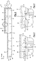
- FIG. 5 illustrates a section view of a portion of a battery pack according to another exemplary embodiment of the present disclosure.
- FIG. 6 illustrates a top view of a portion of the battery pack of FIG. 5 .
- This disclosure relates to a traction battery enclosure of an electrified vehicle.
- the enclosure includes at least one rib. If a load is applied to the electrified vehicle, the rib can help to direct a load path of the load away from certain components housed within the traction battery enclosure, especially relatively sensitive components such as sense lead connector assemblies.
- FIG. 1 schematically illustrates a powertrain 10 for an electrified vehicle.
- HEV hybrid electric vehicle
- PHEVs plug-in hybrid electric vehicles
- BEVs battery electric vehicles
- fuel cell vehicles etc.
- the powertrain 10 includes a battery pack 14 having a plurality of battery arrays 18 , an internal combustion engine 20 , a motor 22 , and a generator 24 .
- the motor 22 and the generator 24 are types of electric machines.
- the motor 22 and generator 24 may be separate or have the form of a combined motor-generator.
- the battery pack 14 is used in connection with the BEV architecture rather than the depicted HEV.
- the powertrain 10 is a power-split powertrain that employs a first drive system and a second drive system.
- the first and second drive systems generate torque to drive one or more sets of vehicle drive wheels 28 .
- the first drive system includes a combination of the engine 20 and the generator 24 .
- the second drive system includes at least the motor 22 , the generator 24 , and the battery pack 14 .
- the motor 22 and the generator 24 are portions of an electric drive system of the powertrain 10 .
- the engine 20 and the generator 24 can be connected through a power transfer unit 30 , such as a planetary gear set.
- a power transfer unit 30 such as a planetary gear set.
- the power transfer unit 30 is a planetary gear set that includes a ring gear 32 , a sun gear 34 , and a carrier assembly 36 .
- the generator 24 can be driven by the engine 20 through the power transfer unit 30 to convert kinetic energy to electrical energy.
- the generator 24 can alternatively function as a motor to convert electrical energy into kinetic energy, thereby outputting torque to a shaft 38 connected to the power transfer unit 30 .
- the ring gear 32 of the power transfer unit 30 is connected to a shaft 40 , which is connected to the vehicle drive wheels 28 through a second power transfer unit 44 .
- the second power transfer unit 44 may include a gear set having a plurality of gears 46 .
- Other power transfer units could be used in other examples.
- the gears 46 transfer torque from the engine 20 to a differential 48 to ultimately provide traction to the vehicle drive wheels 28 .
- the differential 48 may include a plurality of gears that enable the transfer of torque to the vehicle drive wheels 28 .
- the second power transfer unit 44 is mechanically coupled to an axle 50 through the differential 48 to distribute torque to the vehicle drive wheels 28 .
- the motor 22 can be selectively employed to drive the vehicle drive wheels 28 by outputting torque to a shaft 52 that is also connected to the second power transfer unit 44 .
- the motor 22 and the generator 24 cooperate as part of a regenerative braking system in which both the motor 22 and the generator 24 can be employed as motors to output torque.
- the motor 22 and the generator 24 can each output electrical power to recharge cells of the battery pack 14 .
- the battery pack 14 includes an enclosure 60 that houses the plurality of battery arrays 18 .
- the enclosure 60 includes a cover 64 secured to a tray 68 to provide an interior 72 .
- the battery arrays 18 are disposed within the interior 72 when the battery arrays 18 are housed by the enclosure 60 .
- the battery arrays 18 are arranged in multiple tiers. In particular, six of the battery arrays 18 are disposed on a lower tier, and three of the battery arrays 18 are disposed on an upper tier that is vertically above the lower tier. Vertical and horizontal, for purposes of this disclosure, are with reference to ground and a general orientation of the battery pack 14 when installed within the vehicle.
- the cover 64 of the enclosure 60 is polymer-based, such as a thermoplastic-based.
- the cover 64 is a sheet molded compound (SMC) material.
- the cover 64 can include reinforcing fibers, such as glass or carbon, or other fillers such as talc or glass beads.
- the tray 68 can be aluminum, or some other type of material.
- the tray 68 is hermetically sealed to the cover at an interface 76 .
- the interface extends circumferentially continuously about a perimeter of the enclosure 60 .
- the enclosure 60 has a plurality of horizontally facing sides 80 extending from a vertically bottom side 84 of the enclosure 60 to a vertically top side 88 of the enclosure 60 .
- the tray 68 provides the vertically bottom side 84 and a portion of the horizontally facing sides 80 .
- the cover 64 provides another portion of the horizontally facing sides 80 , and the vertically top side 88 .
- the enclosure 60 is disposed vertically beneath a floor 92 of a vehicle when the battery pack 14 is in an installed position within the vehicle. Straps, mechanical fasteners, and other structures (not shown) can be used to hold the battery pack 14 in the installed position vertically beneath the floor 92 .
- the vehicle floor can be metal or a metal alloy material.
- a load L such as load due to a rear impact
- the load L can move along a load path that extends through structures of the vehicle such as portions of the floor 92 that are vertically above the battery pack 14 .
- the load L causes the floor 92 to buckle.
- FIG. 3 shows a portion of the floor 92 and a portion of the battery pack 14 prior the load L being directed into the vehicle.
- FIG. 4 shows the floor 92 and portion of the battery pack 14 after the load L has been directed into the vehicle.
- the buckling of the floor 92 causes the floor 92 to move relative to the cover 64 of the enclosure 60 . Movement of the cover 64 can cause the cover 64 to contact components held within the interior 72 and thus the load path to extend into components held within the interior 72 , such as the battery arrays 18 .
- the enclosure 60 of the exemplary battery pack 14 and particularly the cover 64 of the enclosure 60 , includes features utilized to direct the load along a load path that extends away from certain areas of the battery arrays 18 .
- the battery arrays 18 a and 18 b shown in FIGS. 3 and 4 include, among other things, battery cells 100 held within frames 104 .
- Side plates 108 are disposed along the laterally outer peripheries of the battery arrays 18 .
- Each of the battery arrays 18 a and 18 b includes a sense lead connector assembly 112 mounted atop the frames 104 .
- the sense lead connector assembly 112 is, in this example a Hot-At-All-Time (HAAT) sense lead connector.
- Sense leads can be coupled to the battery array 18 a through the sense lead connector assembly 112 .
- the sense leads can help to monitor temperature, voltage of the battery array 18 .
- Wires can operably couple the sense lead connector assembly 112 to a controller module of the vehicle, such as a Battery Pack Control Module.
- FIGS. 3 and 4 show the sense lead connector assembly 112 of the battery array 18 a , but not the sense lead connector assembly of the battery array 18 b .
- the battery cells 100 , the frames 104 , the side plates 108 , and the sense lead connector assembly 112 are all components of the battery arrays 18 a and 18 b .
- the battery arrays 18 a and 18 b also include other components.
- the sense lead connector assembly 112 due to its position vertically atop the frames 104 , extends vertically upward further than the other components of the battery array 18 a .
- the sense lead connector assembly 112 extends vertically above the side plate 108 of the battery array 18 a , and is disposed within the battery pack 14 vertically higher than both the frames 104 and the battery cells 100 . Placing the sense lead connector 112 at this position can, among other things, facilitate assembly.
- sense lead connector assemblies have been recessed within a battery array such that the sense lead connector assemblies were not vertically proud of other portions of the battery array.
- the cover 64 of the enclosure 60 includes a plurality of ribs 120 .
- the ribs 120 extend vertically downward from the first area 124 of the cover. At least a portion of the first area 124 is directly vertically above the side plate 108 of the battery array 18 a . Accordingly, the rib 120 is also directly vertically above the side plate 108 of the battery array 18 a.
- the cover 64 of the enclosure 60 further includes a second area 128 that is directly vertically above the sense lead connector assembly 112 .
- the second area 128 lacks the rib 120 extending into the interior 72 of the enclosure 60 . That is, the exemplary rib 120 does not extend from the second area 128 .
- the battery pack 14 Prior to application of the load L, the battery pack 14 is configured such that a distance D 1 between a downwardly facing surface 132 of the rib 120 and an uppermost surface 136 of the side plate 108 of the battery array 18 a is less than a distance D 2 .
- the distance D 2 represents the distance between the second area of the cover 64 and a vertically uppermost surface 140 of the sense lead connector assembly 112 .
- This configuration causes the rib 120 to directly contacting the side plate 108 of the battery array 18 a when the floor 92 buckles and causes sufficient movement of the cover 64 toward the battery array 18 a .
- the direct contact between the rib 120 and the side plate 108 occurs before the second area 128 of the cover 64 contacts the vertically upper surface 140 of the sense lead connector assembly 112 .
- the direct contact between the rib 120 and the side plate 108 directs the load L along a load path L p that transfers at least some of the load L directly from the rib 120 of the cover 64 to the side plate 108 of the battery array 18 a . This inhibits the load path from extending from the second area 128 of the cover 64 to the sense lead connector assembly 112 .
- the example rib 120 is configured to transfer at least some of the load L to the side plate 108 , the rib 120 could be configured to direct the load to some other structural component of the battery array 18 a.
- the contact between the rib 120 and the side plate 108 effectively inhibits relative movement of the second area 128 toward the sense lead connector assembly 112 due to the buckling of the floor 92 .
- the side plate 108 and other components of the battery array 18 a may be better able to withstand loads than the sense lead connector 112 . Inhibiting movement of the second area 128 , and other portions of the enclosure 60 toward the vehicle sense lead connector assembly 112 , can help to avoid the second area 128 touching down onto the vehicle sense lead connector assembly 112 , which could result in load being transferred to the vehicle sense lead connector assembly 112 . This can help to maintain the integrity of the vehicle sense lead 112 when the load L is applied to the vehicle.
- the rib 120 is used to inhibit load transfer to the sense lead connector 112 in this example.
- the sense lead connector 112 is a battery component that is often considered a relatively sensitive battery component when compared to other components, such as the side plate 108 . Accordingly, avoiding or inhibiting loads being applied to the sense lead connector 112 can be desirable.
- the rib 120 could be used to inhibit load transfer to other types of components in other examples. For example, inhibiting a transfer of load to battery components such as a high voltage terminal, a high voltage buss, high voltage wiring, or wiring associated with the sense lead connector 112 may be desirable.
- the rib 120 has a first horizontal end portion 150 that directly contacts the side plate 108 of the array 18 a after sufficient movement of the rib 120 relative to the side plate 108 .
- the rib 120 further includes an opposite, second horizontal end portion 154 that contacts a side plate 108 of the adjacent array 18 b after sufficient relative movement of the rib 120 .
- the load path L p then transfers load from the rib 120 of the cover into both side plates 108 .
- the rib 120 spans a gap G between the side plate 108 of the battery array 18 a and the side plate 108 of the battery array 18 b.
- the rib 120 is a continuous monolithic portion of the cover 64 in the exemplary embodiment.
- the sheet molded compound material that provides the rib 120 is utilized to provide the remaining portions of the cover 64 . Forming the rib 120 together with the remaining portions of the cover 64 can simplify manufacturing.
- another example cover 64 a includes a rib 120 a configured to contact battery components, here side plates of battery arrays 18 a ′ and 18 b ′, to direct a load around another battery component, here a sense lead connector assembly 112 a .
- the cover 64 a is formed with various corrugations, which can help to strengthen the cover 64 a.
- a vertical distance between the rib 120 and the side plates of the arrays 18 a ′ and 18 b ′ is less than a distance between the sense lead connector assembly 112 a and the portions of the cover 64 a vertically directly above the sense lead connector assembly 112 a .
- a buckling movement of a floor (not shown in FIG. 5 ) causing the cover 64 a to move toward the battery arrays 18 a ′ and 18 b ′ will result in the rib 120 a contacting the side plates of the arrays 18 a ′ and 18 b ′ prior to other portions of the cover 64 a contacting the sense lead connector assembly 112 a.
- the rib 120 a could be designed to have a gap relative to the side plates of the battery arrays 18 a ′ and 18 b ′ prior to application of the load. In another example, the rib 120 a could be designed to directly contact the side plates of the arrays 18 a ′ and 18 b ′ prior to application of the load.
- the cover 64 a may include groupings of the ribs 120 a .
- the arrays 18 a ′ and 18 b ′ can have battery cells 100 and frames 104 (not shown) distributed along an array axis A.
- the groupings of the ribs 120 a can be disposed along an axis aligned with, and spaced from, the array axis A.
- the groupings of the ribs 120 a can be concentrated in areas containing the sense lead assemblies 112 a of the arrays.
Landscapes
- Engineering & Computer Science (AREA)
- Chemical & Material Sciences (AREA)
- General Chemical & Material Sciences (AREA)
- Electrochemistry (AREA)
- Chemical Kinetics & Catalysis (AREA)
- Mechanical Engineering (AREA)
- Transportation (AREA)
- Life Sciences & Earth Sciences (AREA)
- Power Engineering (AREA)
- Sustainable Energy (AREA)
- Sustainable Development (AREA)
- Manufacturing & Machinery (AREA)
- Aviation & Aerospace Engineering (AREA)
- Combustion & Propulsion (AREA)
- Battery Mounting, Suspending (AREA)
Abstract
Description
Claims (20)
Priority Applications (3)
| Application Number | Priority Date | Filing Date | Title |
|---|---|---|---|
| US16/736,920 US11380958B2 (en) | 2020-01-08 | 2020-01-08 | Traction battery enclosure and load directing method |
| CN202011561810.6A CN113097631A (en) | 2020-01-08 | 2020-12-25 | Traction battery housing ribs and load guiding method |
| DE102020134981.5A DE102020134981A1 (en) | 2020-01-08 | 2020-12-28 | TRACTION BATTERY HOUSING RIBS AND LOAD MANAGEMENT PROCEDURES |
Applications Claiming Priority (1)
| Application Number | Priority Date | Filing Date | Title |
|---|---|---|---|
| US16/736,920 US11380958B2 (en) | 2020-01-08 | 2020-01-08 | Traction battery enclosure and load directing method |
Publications (2)
| Publication Number | Publication Date |
|---|---|
| US20210210738A1 US20210210738A1 (en) | 2021-07-08 |
| US11380958B2 true US11380958B2 (en) | 2022-07-05 |
Family
ID=76432386
Family Applications (1)
| Application Number | Title | Priority Date | Filing Date |
|---|---|---|---|
| US16/736,920 Active 2040-10-10 US11380958B2 (en) | 2020-01-08 | 2020-01-08 | Traction battery enclosure and load directing method |
Country Status (3)
| Country | Link |
|---|---|
| US (1) | US11380958B2 (en) |
| CN (1) | CN113097631A (en) |
| DE (1) | DE102020134981A1 (en) |
Cited By (1)
| Publication number | Priority date | Publication date | Assignee | Title |
|---|---|---|---|---|
| US20210288298A1 (en) * | 2020-03-10 | 2021-09-16 | Karma Automotive Llc | Vehicle battery system |
Citations (8)
| Publication number | Priority date | Publication date | Assignee | Title |
|---|---|---|---|---|
| US4265984A (en) * | 1980-02-11 | 1981-05-05 | Duracell International Inc. | Battery housing |
| US20050153195A1 (en) * | 2004-01-13 | 2005-07-14 | Han Kyu N. | Secondary battery |
| US20130180684A1 (en) * | 2010-09-08 | 2013-07-18 | Foshan Shanri Motor Electric Hub Co., Ltd. | Heat dissipation bracket for battery pack assembly |
| KR101381098B1 (en) | 2011-04-13 | 2014-04-04 | 박성찬 | A battery which is improved damageability and repairability about low-speed impact for the electric vehicle |
| CN204577475U (en) | 2015-05-20 | 2015-08-19 | 马鞍山福亨汽车内饰有限公司 | A kind of high-strength vehicle cell cover |
| CN204760453U (en) | 2015-06-23 | 2015-11-11 | 浙江时空能源技术有限公司 | Electric automobile lithium ion battery case that commonality is good |
| CN208093596U (en) | 2017-12-05 | 2018-11-13 | 江苏正崴新能源科技有限公司 | A kind of electric vehicle-mounted battery pack |
| CN208955029U (en) | 2018-09-28 | 2019-06-07 | 桑顿新能源科技有限公司 | A kind of passenger car power battery lightweight superstructure |
-
2020
- 2020-01-08 US US16/736,920 patent/US11380958B2/en active Active
- 2020-12-25 CN CN202011561810.6A patent/CN113097631A/en active Pending
- 2020-12-28 DE DE102020134981.5A patent/DE102020134981A1/en active Pending
Patent Citations (8)
| Publication number | Priority date | Publication date | Assignee | Title |
|---|---|---|---|---|
| US4265984A (en) * | 1980-02-11 | 1981-05-05 | Duracell International Inc. | Battery housing |
| US20050153195A1 (en) * | 2004-01-13 | 2005-07-14 | Han Kyu N. | Secondary battery |
| US20130180684A1 (en) * | 2010-09-08 | 2013-07-18 | Foshan Shanri Motor Electric Hub Co., Ltd. | Heat dissipation bracket for battery pack assembly |
| KR101381098B1 (en) | 2011-04-13 | 2014-04-04 | 박성찬 | A battery which is improved damageability and repairability about low-speed impact for the electric vehicle |
| CN204577475U (en) | 2015-05-20 | 2015-08-19 | 马鞍山福亨汽车内饰有限公司 | A kind of high-strength vehicle cell cover |
| CN204760453U (en) | 2015-06-23 | 2015-11-11 | 浙江时空能源技术有限公司 | Electric automobile lithium ion battery case that commonality is good |
| CN208093596U (en) | 2017-12-05 | 2018-11-13 | 江苏正崴新能源科技有限公司 | A kind of electric vehicle-mounted battery pack |
| CN208955029U (en) | 2018-09-28 | 2019-06-07 | 桑顿新能源科技有限公司 | A kind of passenger car power battery lightweight superstructure |
Cited By (3)
| Publication number | Priority date | Publication date | Assignee | Title |
|---|---|---|---|---|
| US20210288298A1 (en) * | 2020-03-10 | 2021-09-16 | Karma Automotive Llc | Vehicle battery system |
| US11588199B2 (en) * | 2020-03-10 | 2023-02-21 | Karma Automotive Llc | Vehicle battery system |
| US12183904B2 (en) | 2020-03-10 | 2024-12-31 | Karma Automotive Llc | Vehicle battery system |
Also Published As
| Publication number | Publication date |
|---|---|
| US20210210738A1 (en) | 2021-07-08 |
| CN113097631A (en) | 2021-07-09 |
| DE102020134981A1 (en) | 2021-07-08 |
Similar Documents
| Publication | Publication Date | Title |
|---|---|---|
| RU2684972C1 (en) | Battery installation structure | |
| US10971777B2 (en) | Traction battery support assembly and method | |
| US10431791B2 (en) | Traction battery pack shield and shielding method | |
| US10158106B2 (en) | Beam system for electrified vehicle battery packs | |
| US10644281B2 (en) | Battery pack retention assembly and retention method | |
| US20240075799A1 (en) | Traction battery pack support system and method of securing a battery pack to an electrified vehicle | |
| US20230137044A1 (en) | Traction battery pack enclosure assemblies with integrated thermal barrier systems | |
| US11987112B2 (en) | Battery pack enclosure having a sectioned sidewall | |
| US20250192330A1 (en) | Multi-tiered traction battery packs with shared cell stack end plates | |
| US11563250B2 (en) | Battery pack assembly having foam enclosure and method of supporting a foam battery pack enclosure | |
| US20240170767A1 (en) | Traction battery packs with integrated thermal barrier systems | |
| US11380958B2 (en) | Traction battery enclosure and load directing method | |
| US12040501B2 (en) | Impact protection shrouds for protecting battery pack components | |
| US20240297383A1 (en) | Systems and methods for sealing interfaces of traction battery packs | |
| US20250055074A1 (en) | Thermal barrier blanket systems for use within traction battery packs | |
| US20240063511A1 (en) | Traction battery pack busbar supporting assembly and supporting method | |
| US9722229B2 (en) | Electric vehicle battery attachment assembly and method | |
| US12567624B2 (en) | Thermal insulating joints for traction battery packs | |
| US20250337072A1 (en) | Systems and methods for sealing traction battery packs | |
| US11993140B2 (en) | Load transferring battery cell arrangement for traction battery pack | |
| US20250372793A1 (en) | Traction battery pack module attachment system having cleats | |
| US20240204367A1 (en) | Bus bar retention systems for traction battery packs | |
| US20240396140A1 (en) | Systems and methods for sealing interfaces of traction battery packs | |
| US20260005404A1 (en) | Integrated busbar and terminal configuration | |
| US20240113374A1 (en) | Structurally reinforced enclosure covers for traction battery packs |
Legal Events
| Date | Code | Title | Description |
|---|---|---|---|
| AS | Assignment |
Owner name: FORD GLOBAL TECHNOLOGIES, LLC, MICHIGAN Free format text: ASSIGNMENT OF ASSIGNORS INTEREST;ASSIGNORS:FARHA, EID;KHANDELWAL, HIMANSHU;CARDOSO, JESUS;AND OTHERS;SIGNING DATES FROM 20200106 TO 20200107;REEL/FRAME:051445/0946 |
|
| FEPP | Fee payment procedure |
Free format text: ENTITY STATUS SET TO UNDISCOUNTED (ORIGINAL EVENT CODE: BIG.); ENTITY STATUS OF PATENT OWNER: LARGE ENTITY |
|
| STPP | Information on status: patent application and granting procedure in general |
Free format text: DOCKETED NEW CASE - READY FOR EXAMINATION |
|
| STPP | Information on status: patent application and granting procedure in general |
Free format text: NON FINAL ACTION MAILED |
|
| STPP | Information on status: patent application and granting procedure in general |
Free format text: RESPONSE TO NON-FINAL OFFICE ACTION ENTERED AND FORWARDED TO EXAMINER |
|
| STPP | Information on status: patent application and granting procedure in general |
Free format text: NOTICE OF ALLOWANCE MAILED -- APPLICATION RECEIVED IN OFFICE OF PUBLICATIONS |
|
| STPP | Information on status: patent application and granting procedure in general |
Free format text: PUBLICATIONS -- ISSUE FEE PAYMENT VERIFIED |
|
| STCF | Information on status: patent grant |
Free format text: PATENTED CASE |
|
| MAFP | Maintenance fee payment |
Free format text: PAYMENT OF MAINTENANCE FEE, 4TH YEAR, LARGE ENTITY (ORIGINAL EVENT CODE: M1551); ENTITY STATUS OF PATENT OWNER: LARGE ENTITY Year of fee payment: 4 |