US11370688B2 - Method of molding optical element and optical element molding die - Google Patents

Method of molding optical element and optical element molding die Download PDF

Info

Publication number
US11370688B2
US11370688B2 US16/820,797 US202016820797A US11370688B2 US 11370688 B2 US11370688 B2 US 11370688B2 US 202016820797 A US202016820797 A US 202016820797A US 11370688 B2 US11370688 B2 US 11370688B2
Authority
US
United States
Prior art keywords
die
molding
optical element
side die
hole
Prior art date
Legal status (The legal status is an assumption and is not a legal conclusion. Google has not performed a legal analysis and makes no representation as to the accuracy of the status listed.)
Active, expires
Application number
US16/820,797
Other versions
US20200216347A1 (en
Inventor
Kenji Kikuchi
Current Assignee (The listed assignees may be inaccurate. Google has not performed a legal analysis and makes no representation or warranty as to the accuracy of the list.)
Olympus Corp
Original Assignee
Olympus Corp
Priority date (The priority date is an assumption and is not a legal conclusion. Google has not performed a legal analysis and makes no representation as to the accuracy of the date listed.)
Filing date
Publication date
Application filed by Olympus Corp filed Critical Olympus Corp
Assigned to OLYMPUS CORPORATION reassignment OLYMPUS CORPORATION ASSIGNMENT OF ASSIGNORS INTEREST (SEE DOCUMENT FOR DETAILS). Assignors: KIKUCHI, KENJI
Publication of US20200216347A1 publication Critical patent/US20200216347A1/en
Application granted granted Critical
Publication of US11370688B2 publication Critical patent/US11370688B2/en
Active legal-status Critical Current
Adjusted expiration legal-status Critical

Links

Images

Classifications

    • CCHEMISTRY; METALLURGY
    • C03GLASS; MINERAL OR SLAG WOOL
    • C03BMANUFACTURE, SHAPING, OR SUPPLEMENTARY PROCESSES
    • C03B11/00Pressing molten glass or performed glass reheated to equivalent low viscosity without blowing
    • C03B11/06Construction of plunger or mould
    • C03B11/08Construction of plunger or mould for making solid articles, e.g. lenses
    • CCHEMISTRY; METALLURGY
    • C03GLASS; MINERAL OR SLAG WOOL
    • C03BMANUFACTURE, SHAPING, OR SUPPLEMENTARY PROCESSES
    • C03B11/00Pressing molten glass or performed glass reheated to equivalent low viscosity without blowing
    • C03B11/12Cooling, heating, or insulating the plunger, the mould, or the glass-pressing machine; cooling or heating of the glass in the mould
    • C03B11/122Heating
    • GPHYSICS
    • G02OPTICS
    • G02BOPTICAL ELEMENTS, SYSTEMS OR APPARATUS
    • G02B3/00Simple or compound lenses
    • BPERFORMING OPERATIONS; TRANSPORTING
    • B29WORKING OF PLASTICS; WORKING OF SUBSTANCES IN A PLASTIC STATE IN GENERAL
    • B29CSHAPING OR JOINING OF PLASTICS; SHAPING OF MATERIAL IN A PLASTIC STATE, NOT OTHERWISE PROVIDED FOR; AFTER-TREATMENT OF THE SHAPED PRODUCTS, e.g. REPAIRING
    • B29C43/00Compression moulding, i.e. applying external pressure to flow the moulding material; Apparatus therefor
    • B29C43/32Component parts, details or accessories; Auxiliary operations
    • B29C43/36Moulds for making articles of definite length, i.e. discrete articles
    • B29C43/361Moulds for making articles of definite length, i.e. discrete articles with pressing members independently movable of the parts for opening or closing the mould, e.g. movable pistons
    • CCHEMISTRY; METALLURGY
    • C03GLASS; MINERAL OR SLAG WOOL
    • C03BMANUFACTURE, SHAPING, OR SUPPLEMENTARY PROCESSES
    • C03B2215/00Press-moulding glass
    • C03B2215/40Product characteristics
    • C03B2215/46Lenses, e.g. bi-convex
    • CCHEMISTRY; METALLURGY
    • C03GLASS; MINERAL OR SLAG WOOL
    • C03BMANUFACTURE, SHAPING, OR SUPPLEMENTARY PROCESSES
    • C03B2215/00Press-moulding glass
    • C03B2215/50Structural details of the press-mould assembly
    • CCHEMISTRY; METALLURGY
    • C03GLASS; MINERAL OR SLAG WOOL
    • C03BMANUFACTURE, SHAPING, OR SUPPLEMENTARY PROCESSES
    • C03B2215/00Press-moulding glass
    • C03B2215/65Means for releasing gas trapped between glass and press die
    • CCHEMISTRY; METALLURGY
    • C03GLASS; MINERAL OR SLAG WOOL
    • C03BMANUFACTURE, SHAPING, OR SUPPLEMENTARY PROCESSES
    • C03B2215/00Press-moulding glass
    • C03B2215/66Means for providing special atmospheres, e.g. reduced pressure, inert gas, reducing gas, clean room

Definitions

  • This disclosure relates to a method of molding an optical element and an optical element molding die.
  • JP 2004-339039 A As one of methods for molding an optical element such as a glass lens, for example, as disclosed in JP 2004-339039 A, there is known a molding method in which the shape of a die is transferred to a glass material by heating and pressing the glass material (mold material) with the die.
  • the cost including also the cost of post-steps can be reduced by molding also a side surface together with functional optical surfaces to be provided in upper and lower surfaces of an optical element.
  • an optical element is molded with a die including an upper die 61 having an upper molding surface 61 a , a lower die 62 having a lower molding surface 62 a , and a side die 63 having a side molding surface 63 a .
  • a mold material M is disposed on the lower die 62 inserted into the side die 63 having a tubular shape as illustrated in the same drawing and heating is performed, the upper die 61 moves with respect to the lower die 62 as illustrated in FIG. 21 ; and thereby, the mold material M is press molded.
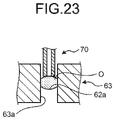
  • an optical element O is taken out of the die, as illustrated in FIG. 23 , by suctioning an upper surface of the optical element O with a suctioning tool 70 .
  • the optical element O with a diameter of less than 1 mm which is very small is molded, for example, as illustrated in FIG. 24
  • a diameter D 1 of the optical element O is smaller than a width W of the suctioning tool 70
  • FIG. 25 after the optical element O after molding is pushed upward from the side die 63 by moving the lower die 62 with respect to the side die 63 , the optical element O is taken out of the die by the suctioning tool 70 .
  • a method of molding an optical element to obtain the molded optical element includes: preparing a die set including an upper die having an upper molding surface, a lower die having a lower molding surface, a side die in which a through hole serving as a side molding surface is formed, and a sleeve configured to accommodate the upper die, the lower die, and the side die; disposing a mold material on the lower molding surface after inserting the lower die into the through hole of the side die in order for the lower molding surface to be positioned in the through hole of the side die; heating the mold material disposed in the through hole of the side die; press molding the mold material with the upper die and the lower die by pushing the side die upward using the lower die to integrally move the side die and the lower die with respect to the upper die and the sleeve in a state where a position of the lower molding surface in the through hole of the side die is maintained at a predetermined position; and pushing the optical element upward by raising the lower die with respect to the side die and the
  • an optical element molding die configured to mold an optical element.
  • the die includes: an upper die having an upper molding surface; a side die in which a through hole serving as a side molding surface is formed; a lower die having a lower molding surface to be disposed in the through hole of the side die; and a sleeve configured to accommodate the upper die, the lower die, and the side die.
  • the lower die is configured to come into a state where the lower die pushes the side die upward to move integrally with the side die with respect to the upper die and the sleeve in a state where a position of the lower molding surface in the through hole of the side die is maintained at a predetermined position, and a state where the lower die is raised with respect to the side die and the sleeve to move with respect to the upper die in order for the position of the lower molding surface in the through hole of the side die to reach a position which is higher than the predetermined position and which is in a vicinity of an upper surface of the side die.
  • FIG. 1 is a cross-sectional view illustrating the configuration of main parts of a molding device including an optical element molding die according to a first embodiment of this disclosure
  • FIG. 2 is a perspective view illustrating a lower die and a side die of the optical element molding die according to the first embodiment of this disclosure, and is a view in which facing surfaces of the lower die and the side die can be seen;
  • FIG. 3 is a cross-sectional view illustrating a state where in the lower die and the side die of the optical element molding die according to the first embodiment of this disclosure, a protrusion portion of the lower die is not fitted into a recess portion of the side die;
  • FIG. 4 is a cross-sectional view illustrating a state where in the lower die and the side die of the optical element molding die according to the first embodiment of this disclosure, the protrusion portion of the lower die is fitted into the recess portion of the side die;
  • FIG. 5 is a cross-sectional view illustrating the mode of a disposition step in a method of molding an optical element using the optical element molding die according to the first embodiment of this disclosure
  • FIG. 6 is a cross-sectional view illustrating the mode of a press molding step in the method of molding an optical element using the optical element molding die according to the first embodiment of this disclosure
  • FIG. 7 is a cross-sectional view illustrating the mode of a push-up step and a take-out step in the method of molding an optical element using the optical element molding die according to the first embodiment of this disclosure
  • FIG. 8 is a perspective view illustrating a lower die and a side die of an optical element molding die according to a modification example of the first embodiment of this disclosure, and is a view in which facing surfaces of the lower die and the side die can be seen;
  • FIG. 9 is a cross-sectional view illustrating a state where in the lower die and the side die of the optical element molding die according to the modification example of the first embodiment of this disclosure, a protrusion portion of the side die is not fitted into a recess portion of the lower die;
  • FIG. 10 is a cross-sectional view illustrating a state where in the lower die and the side die of the optical element molding die according to the modification example of the first embodiment of this disclosure, the protrusion portion of the side die is fitted into the recess portion of the lower die;
  • FIG. 11 is a perspective view illustrating the configuration of a lower die and a side die of an optical element molding die according to a second embodiment of this disclosure
  • FIG. 12 is a cross-sectional view illustrating the mode of the disposition step in a method of molding an optical element using the optical element molding die according to the second embodiment of this disclosure
  • FIG. 13 is a cross-sectional view illustrating the mode of the press molding step in the method of molding an optical element using the optical element molding die according to the second embodiment of this disclosure
  • FIG. 14 is a cross-sectional view illustrating the mode of the push-up step and the take-out step in the method of molding an optical element using the optical element molding die according to the second embodiment of this disclosure;
  • FIG. 15 is a perspective view illustrating the configuration of the lower die and the side die of an optical element molding die according to a modification example of the second embodiment of this disclosure
  • FIG. 16 is a perspective view illustrating a lower die, the side die, and an elastic member of an optical element molding die according to a third embodiment of this disclosure, and is a view in which facing surfaces of the lower die and the side die can be seen;
  • FIG. 17 is a cross-sectional view illustrating the mode of the disposition step in a method of molding an optical element using the optical element molding die according to the third embodiment of this disclosure.
  • FIG. 18 is a cross-sectional view illustrating the mode of the press molding step in the method of molding an optical element using the optical element molding die according to the third embodiment of this disclosure
  • FIG. 19 is a cross-sectional view illustrating the mode of the push-up step and the take-out step in the method of molding an optical element using the optical element molding die according to the third embodiment of this disclosure
  • FIG. 20 is a cross-sectional view illustrating the mode of a disposition step in a method of molding an optical element using an optical element molding die according to the related art
  • FIG. 21 is a cross-sectional view illustrating the mode of a press molding step in the method of molding an optical element using the optical element molding die according to the related art
  • FIG. 22 is a cross-sectional view illustrating a mode where an upper die is raised after the press molding step in the method of molding an optical element using the optical element molding die according to the related art
  • FIG. 23 is a cross-sectional view illustrating the mode of a take-out step in the method of molding an optical element using the optical element molding die according to the related art
  • FIG. 24 is a cross-sectional view illustrating an example of the diameter of an optical element after molding and the width of a suctioning tool in the method of molding an optical element using the optical element molding die according to the related art.
  • FIG. 25 is a cross-sectional view illustrating the mode of a push-up step and a take-out step in the method of molding an optical element using the optical element molding die according to the related art.
  • a molding device 1 molds an optical element (for example, a glass lens) by press molding a mold material (for example, a glass material) M that is heated and softened.
  • the molding device 1 includes mainly a die set (optical element molding die) 10 , a gas replacement chamber 20 , and a molding chamber 30 .
  • the gas replacement chamber 20 air inside the die set 10 which is transported by a transport arm (not illustrated) or the like is replaced with an inert gas such as nitrogen.
  • the die set 10 after subjected to the gas replacement is transported to the molding chamber 30 by the transport arm (not illustrated).
  • the molding chamber 30 includes an upper plate 31 and a lower plate 32 that heat, press mold, and cool the transported die set 10 in a state where the die set 10 is interposed therebetween.
  • the lower plate 32 includes a push pin 33 .
  • the push pin 33 pushes a lower die 12 toward the direction of an upper die 11 when press molding is performed, and is connected to a push mechanism (not illustrated).
  • the die set 10 includes the upper die 11 , the lower die 12 , a side die 13 , and a sleeve 14 .
  • the upper die 11 has an upper molding surface 11 a for molding a functional upper optical surface of the optical element.
  • the upper die 11 includes a protrusion portion 111 having a cylindrical shape, and a distal end surface of the protrusion portion 111 forms the upper molding surface 11 a .
  • the upper die 11 is mounted on an upper end portion of the sleeve 14 .
  • the lower die 12 has a lower molding surface 12 a for molding a functional lower optical surface of the optical element.
  • the lower molding surface 12 a is disposed in a through hole 133 of the side die 13 .
  • the side die 13 has a side molding surface 13 a for forming a side surface of the optical element.
  • the upper die 11 and the lower die 12 are disposed such that the molding surfaces of the upper die 11 and the lower die 12 face each other in a state where the side die 13 is interposed therebetween.
  • the lower die 12 includes a main body portion 121 having a cylindrical shape, a protrusion portion 122 which protrudes from an upper surface 121 a of the main body portion 121 , and a protrusion portion 123 having a cylindrical shape which protrudes from an upper surface 122 a of the protrusion portion 122 .
  • a distal end surface of the protrusion portion 123 forms the lower molding surface 12 a of the lower die 12 .
  • the lower die 12 is configured to be able to come into a state where the lower die 12 moves integrally with the side die 13 with respect to the upper die 11 in a state where the position of the lower molding surface 12 a in the through hole 133 of the side die 13 is maintained at a predetermined position, and a state where the lower die 12 moves with respect to the upper die 11 such that the position of the lower molding surface 12 a in the through hole 133 of the side die 13 reaches a position which is higher than the above-described predetermined position and in the vicinity of an upper surface 131 a of the side die 13 , which will be described later.
  • the side die 13 includes a main body portion 131 having a cylindrical shape and a recess portion 132 with a predetermined depth which is formed in a lower surface 131 b of the main body portion 131 .
  • the recess portion 132 is formed into a shape corresponding to that of the protrusion portion 122 of the lower die 12 .
  • a through hole 133 penetrating through the main body portion 131 is formed in a bottom surface 132 a of the recess portion 132 .
  • An inner peripheral surface of the through hole 133 forms the side molding surface 13 a of the side die 13 .
  • the through hole 133 is configured such that the protrusion portion 111 of the upper die 11 and the protrusion portion 123 of the lower die 12 which are described above can be inserted thereinto.
  • stepped shapes which can be fitted into each other are formed in the facing surfaces of the lower die 12 and the side die 13 , namely, in the upper surface 121 a of the main body portion 121 of the lower die 12 and the lower surface 131 b of the main body portion 131 of the side die 13 .
  • the protrusion portion 122 is formed on the upper surface 121 a of the lower die 12
  • the recess portion 132 having the shape corresponding to that of the protrusion portion 122 is formed on the lower surface 131 b of the side die 13 .
  • the lower die 12 comes into the state where the position of the lower molding surface 12 a in the through hole 133 of the side die 13 is maintained at a predetermined position A.
  • a disposition step, a gas replacement step, a heating step, a press molding step, and a cooling step are performed in a state where the lower die 12 and the side die 13 are disposed as illustrated in the same drawing.
  • the lower die 12 comes into the state where the position of the lower molding surface 12 a in the through hole 133 of the side die 13 reaches a position higher than the predetermined position A, namely, a position B in the vicinity of the upper surface 131 a of the side die 13 .
  • a push-up step and a take-out step are performed in a state where the lower die 12 and the side die 13 are disposed as illustrated in the same drawing.
  • the state where the recess portion 132 of the side die 13 is in contact with the protrusion portion 122 of the lower die 12 includes also states other than the state illustrated in FIG. 4 . Namely, in the same drawing, since the height of the protrusion portion 122 of the lower die 12 is the same as the depth of the recess portion 132 of the side die 13 , the bottom surface 132 a of the recess portion 132 of the side die 13 comes into a state of contact with the upper surface 122 a of the protrusion portion 122 of the lower die 12 , and the lower surface 131 b of the main body portion 131 of the side die 13 comes into a state of contact with the upper surface 121 a of the main body portion 121 of the lower die 12 .
  • the bottom surface 132 a of the recess portion 132 of the side die 13 comes into a state of contact only with the upper surface 122 a of the protrusion portion 122 of the lower die 12 , but the lower surface 131 b of the main body portion 131 of the side die 13 does not come into a state of contact with the upper surface 121 a of the main body portion 121 of the lower die 12 .
  • the lower surface 131 b of the main body portion 131 of the side die 13 comes into a state of contact only with the upper surface 121 a of the main body portion 121 of the lower die 12 , but the bottom surface 132 a of the recess portion 132 of the side die 13 does not come into a state of contact with the upper surface 122 a of the protrusion portion 122 of the lower die 12 .
  • the state where the recess portion 132 of the side die 13 is in contact with the protrusion portion 122 of the lower die 12 includes also a state where only either the upper surface 122 a is in contact with the bottom surface 132 a or the upper surface 121 a is in contact with the lower surface 131 b.
  • the sleeve 14 is formed into a tubular shape, and a through hole 14 a through which an inert gas is introduced into the die set 10 in the gas replacement step of the method of molding an optical element which is will be described later is formed in the sleeve 14 .
  • the disposition step, the gas replacement step, the heating step, the press molding step, the cooling step, the push-up step, and the take-out step are performed in order.
  • the lower die 12 and the side die 13 are disposed inside the sleeve 14 such that similarly to FIG. 3 described above, the lower surface 131 b of the main body portion 131 of the side die 13 is in contact with the upper surface 122 a of the protrusion portion 122 of the lower die 12 .
  • the protrusion portion 123 of the lower die 12 is inserted into the through hole 133 of the side die 13 such that the lower molding surface 12 a is positioned in the through hole 133 of the side die 13 .
  • a mold material M having a regulated volume is disposed on the lower molding surface 12 a of the lower die 12 .
  • the shape of the mold material M is not limited to a ball shape, and may be a circular disk shape or the shape of a lens that is processed into an approximately spherical shape in advance.
  • the upper die 11 is mounted on an upper end surface of the sleeve 14 . Incidentally, when the upper die 11 is mounted on the upper end surface of the sleeve 14 , the height of each member of the die set 10 is adjusted such that a predetermined distance D 2 is formed between the upper molding surface 11 a of the upper die 11 and the upper surface 131 a of the main body portion 131 of the side die 13 .
  • the die set 10 in which the upper die 11 , the lower die 12 , the side die 13 , and the mold material M are disposed inside the sleeve 14 is transported to the gas replacement chamber 20 of the molding device 1 illustrated in FIG. 1 .
  • the entire air of the gas replacement chamber 20 is replaced with an inert gas (for example, a nitrogen gas) in a state where, as illustrated in FIG. 5 , the upper molding surface 11 a of the upper die 11 is positioned out of the through hole 133 of the side die 13 . Therefore, the nitrogen gas is introduced into the die set 10 from the through hole 14 a of the sleeve 14 , and air in the through hole 133 of the side die 13 in which the mold material M is disposed is replaced with the nitrogen gas.
  • an inert gas for example, a nitrogen gas
  • the nitrogen replacement in order to make sure a reliable nitrogen replacement, the nitrogen replacement may be performed by filling the gas replacement chamber 20 with the nitrogen gas after depressurizing the gas replacement chamber 20 at atmospheric pressure using a vacuum pump (not illustrated) before the nitrogen replacement.
  • the mold material M flies out of the through hole 133 of the side die 13 depending on the shape or the mass of the mold material M. Therefore, in order to prevent the mold material M from flying out thereof as described above, it is preferable that the distance D 2 between the upper molding surface 11 a of the upper die 11 and the upper surface 131 a of the main body portion 131 of the side die 13 is smaller than the thickness of the mold material M.
  • the die set 10 after subjected to the nitrogen replacement is transported to the molding chamber 30 of the molding device 1 which is illustrated in FIG. 1 . Then, the die set 10 transported to the molding chamber 30 is interposed between the upper plate 31 and the lower plate 32 , and the die set 10 and the mold material M that is disposed in the through hole 133 of the side die 13 are heated to the yield point temperature of the mold material M or greater.
  • the press molding step the push pin 33 (refer to FIG. 1 ) is raised by the push mechanism (not illustrated); and thereby, the side die 13 and the lower die 12 are raised.
  • the press molding step is performed, as illustrated in FIG. 6 , in a state where the lower surface 131 b of the main body portion 131 of the side die 13 is in contact with the upper surface 122 a of the protrusion portion 122 of the lower die 12 . Therefore, the side die 13 and the lower die 12 move integrally with respect to the upper die 11 in a state where the position of the lower molding surface 12 a in the through hole 133 of the side die 13 is maintained at the predetermined position; and thereby, the mold material M is press molded with the upper die 11 and the lower die 12 .
  • the side die 13 and the lower die 12 are integrally raised inside the sleeve 14 in a state where the height of the lower molding surface 12 a in the through hole 133 of the side die 13 is maintained.
  • the upper molding surface 11 a of the upper die 11 is inserted into the through hole 133 of the side die 13 .
  • the mold material M is pressed in the through hole 133 to be molded into a lens shape by the upper molding surface 11 a and the lower molding surface 12 a.
  • the die set 10 is transported out of the molding device 1 . Then, the die set 10 outside the molding device 1 is further cooled close to a room temperature.
  • the upper die 11 is removed from the die set 10 .
  • the lower molding surface 12 a of the lower die 12 in the through hole 133 of the side die 13 moves to a position which is higher relative to the position in the press molding step and at which at least a part of the optical element O after molding protrudes from the upper surface 131 a of the main body portion 131 of the side die 13 .
  • the orientation of the stepped shape of the side die 13 with respect to that of the stepped shape of the lower die 12 in the press molding step is switched to an orientation where the stepped shapes are fitted into each other; and thereby, the lower molding surface 12 a moves in the through hole 133 of the side die 13 .
  • the above-described “orientation of the stepped shape” indicates the orientation of the boundary line between the upper surface 121 a of the main body portion 121 and the protrusion portion 122
  • the above-described “orientation of the stepped shape” indicates the orientation of the boundary line between the lower surface 131 b of the main body portion 131 and the recess portion 132 .
  • the orientation of the stepped shape of the side die 13 is aligned with that of the stepped shape of the lower die 12 , for example, by rotating the side die 13 in the above-described state (refer to FIG. 6 ) in the press molding step by 90° around the axis of the through hole 133 . Then, the bottom surface 132 a of the recess portion 132 of the side die 13 comes into contact with the upper surface 122 a of the protrusion portion 122 of the lower die 12 , and the protrusion portion 122 and the recess portion 132 are fitted into each other. Therefore, the side die 13 is lowered with respect to the lower die 12 , and the lower molding surface 12 a is raised in the through hole 133 of the side die 13 relatively. Then, the optical element O is pushed upward out of the through hole 133 .
  • the side die 13 is lowered and the protrusion portion 122 and the recess portion 132 are fitted into each other by rotating the side die 13 by 90° around the axis of the through hole 133 in a state where the lower die 12 is fixed; however, on the contrary, the lower die 12 may be raised and the protrusion portion 122 and the recess portion 132 may be fitted into each other by rotating the lower die 12 by 90° around the axis of the through hole 133 in a state where the side die 13 is fixed.
  • the optical element O which is pushed out of the through hole 133 of the side die 13 is taken out of the die set 10 by a suctioning tool 70 .
  • the method of molding the optical element O using the die set 10 when the mold material M is molded, since press molding can be performed by integrally moving the side die 13 and the lower die 12 without moving the upper die 11 , it is not necessary to independently drive the upper die 11 , and it is possible to simplify the configuration of the molding device 1 .
  • the method of molding the optical element O when the optical element O after molding is taken out from the die set 10 , it is possible to push the optical element O out from the through hole 133 of the side die 13 , and thus, also in a case where the optical element O with a very small diameter is molded, it is possible to easily take out the optical element O.
  • the upper molding surface 11 a of the upper die 11 is positioned above the upper surface 131 a of the main body portion 131 of the side die 13 when nitrogen replacement is performed (refer to FIG. 5 ), it is possible to perform the nitrogen replacement in a state where the through hole 133 of the side die 13 is released. Therefore, also when the nitrogen replacement is performed, it is not necessary to independently drive the upper die 11 , and it is possible to simplify the configuration of the molding device 1 .
  • FIGS. 8 to 10 The configuration of a die set according to a modification example of the first embodiment of this disclosure will be described with reference to FIGS. 8 to 10 .
  • the configuration of the die set according to this modification example is same as that of the die set 10 (refer to FIG. 5 ) described above. Therefore, hereinafter, the illustration and description of the configuration other than the lower die 12 A and the side die 13 A will be omitted.
  • the molding device 1 similarly to the case of the die set 10 , the molding device 1 (refer to FIG. 1 ) described above is used.
  • the lower die 12 A includes a main body portion 121 A having a cylindrical shape, a recess portion 124 with a predetermined depth which is formed in the upper surface 121 a of the main body portion 121 A, and the protrusion portion 123 having a cylindrical shape which protrudes from a bottom surface 124 a of the recess portion 124 .
  • the distal end surface of the protrusion portion 123 forms the lower molding surface 12 a of the lower die 12 A.
  • the side die 13 A includes a main body portion 131 A having a cylindrical shape and a protrusion portion 134 that protrudes from the lower surface 131 b of the main body portion 131 A.
  • the protrusion portion 134 is formed into a shape corresponding to that of the recess portion 124 of the lower die 12 A.
  • the through hole 133 penetrating through the protrusion portion 134 and the main body portion 131 A is formed in a lower surface 134 a of the protrusion portion 134 .
  • the inner peripheral surface of the through hole 133 forms the side molding surface 13 a of the side die 13 A.
  • the stepped shapes of the lower die 12 A and the side die 13 A are reversed compared to those of the lower die 12 and the side die 13 of the die set 10 described above.
  • the recess portion 124 is formed in the upper surface 121 a of the lower die 12 A
  • the protrusion portion 134 having a shape corresponding to that of the recess portion 124 is formed on the lower surface 131 b of the side die 13 A.
  • the lower die 12 A comes into a state where the position of the lower molding surface 12 a in the through hole 133 of the side die 13 A is maintained at the predetermined position A.
  • the disposition step, the gas replacement step, the heating step, the press molding step, and the cooling step are performed in a state where the lower die 12 A and the side die 13 A are disposed as illustrated in the same drawing.
  • the lower die 12 A comes into a state where the position of the lower molding surface 12 a in the through hole 133 of the side die 13 A reaches a position higher than the predetermined position A, namely, the position B in the vicinity of the upper surface 131 a of the side die 13 A.
  • the push-up step and the take-out step are performed in a state where the lower die 12 A and the side die 13 A are disposed as illustrated in the same drawing.
  • the die set with the above-described configuration according to this modification example is used in molding the optical element O
  • the die set 10 described above it is possible to perform press molding by integrally moving the side die 13 A and the lower die 12 A; and thereby, it is possible to simplify the configuration of the molding device 1 .
  • FIG. 12 illustrates the cross-sectional shape of the die set 10 A as cut along a direction X-X illustrated in FIG. 11 .
  • the die set 10 A includes the upper die 11 , a lower die 12 B, a side die 13 B, a sleeve 14 A, and a spacer 15 .
  • the lower die 12 B includes a main body portion 121 B having a cylindrical shape and the protrusion portion 123 having a cylindrical shape which protrudes from the upper surface 121 a of the main body portion 121 B.
  • the distal end surface of the protrusion portion 123 forms the lower molding surface 12 a of the lower die 12 B.
  • the side die 13 B is formed into a tubular shape, and the through hole 133 is formed at the center of the side die 13 B.
  • the inner peripheral surface of the through hole 133 forms the side molding surface 13 a of the side die 13 B.
  • the through hole 133 is configured such that the protrusion portion 111 of the upper die 11 and the protrusion portion 123 of the lower die 12 B can be inserted thereinto.
  • the sleeve 14 A is formed into a tubular shape.
  • the through hole 14 a through which an inert gas is introduced into the die set 10 A in the gas replacement step of a method of molding the optical element O which will be described later, and a through hole 14 b through which the spacer 15 is inserted into the sleeve 14 A are formed in the sleeve 14 A.
  • the spacer 15 is formed into a U shape, and a notch 151 having such a width that the protrusion portion 123 of the lower die 12 B can be fitted into the notch 151 is formed in the spacer 15 .
  • the spacer 15 is inserted into the sleeve 14 A through the through hole 14 b of the sleeve 14 A, and is detachably disposed between the side die 13 B and the lower die 12 B.
  • the lower die 12 B comes into a state where the position of the lower molding surface 12 a of the lower die 12 B in the through hole 133 of the side die 13 B is maintained at a predetermined position.
  • the disposition step, the gas replacement step, the heating step, the press molding step, and the cooling step are performed in a state where the spacer 15 is installed as illustrated in the same drawings.
  • the lower die 12 B comes into a state where the position of the lower molding surface 12 a of the lower die 12 B in the through hole 133 of the side die 13 B reaches a position higher than the above-described predetermined position, namely, a position in the vicinity of the upper surface 131 a of the side die 13 B.
  • the push-up step and the take-out step are performed in a state where the spacer 15 is not installed as illustrated in the same drawing.
  • the disposition step, the gas replacement step, the heating step, the press molding step, the cooling step, the push-up step, and the take-out step are performed in order.
  • the gas replacement step, the heating step, the cooling step, and the take-out step are the same as those in the method of molding the optical element O according to the first embodiment, and thus, the description thereof will be omitted.
  • the method of molding the optical element O according to this embodiment is performed using the molding device 1 (refer to FIG. 1 ).
  • the spacer 15 is installed between the side die 13 B and the lower die 12 B. Then, the protrusion portion 123 of the lower die 12 B is inserted into the through hole 133 of the side die 13 B such that the lower molding surface 12 a is positioned in the through hole 133 of the side die 13 B.
  • the mold material M having a regulated volume is disposed on the lower molding surface 12 a of the lower die 12 B.
  • the shape of the mold material M is not limited to a ball shape, and may be a circular disk shape or the shape of a lens that is processed into an approximately spherical shape in advance.
  • the upper die 11 is mounted on an upper end surface of the sleeve 14 A. Incidentally, when the upper die 11 is mounted on the upper end surface of the sleeve 14 A, the height of each member of the die set 10 A is adjusted such that the predetermined distance D 2 is formed between the upper molding surface 11 a of the upper die 11 and the upper surface 131 a of the side die 13 B.
  • the press molding step the push pin 33 (refer to FIG. 1 ) is raised by the push mechanism (not illustrated); and thereby, the side die 13 B, the spacer 15 , and the lower die 12 B are raised.
  • the press molding step is performed in a state where, as illustrated in FIG. 13 , the spacer 15 is installed between the side die 13 B and the lower die 12 B. Therefore, the side die 13 B, the spacer 15 , and the lower die 12 B move integrally with respect to the upper die 11 in a state where the position of the lower molding surface 12 a in the through hole 133 of the side die 13 B is maintained at the predetermined position; and thereby, the mold material M is press molded with the upper die 11 and the lower die 12 B.
  • the side die 13 B, the spacer 15 , and the lower die 12 B are integrally raised inside the sleeve 14 A in a state where the height of the lower molding surface 12 a in the through hole 133 of the side die 13 B is maintained.
  • the upper molding surface 11 a of the upper die 11 is inserted into the through hole 133 of the side die 13 B.
  • the mold material M is pressed in the through hole 133 to be molded into a lens shape by the upper molding surface 11 a and the lower molding surface 12 a.
  • the upper die 11 is removed from the die set 10 A.
  • the spacer 15 installed between the side die 13 B and the lower die 12 B is removed; and thereby, the lower molding surface 12 a of the lower die 12 B in the through hole 133 of the side die 13 B moves to a position which is higher relative to the position in the press molding step and at which at least a part of the optical element O after molding protrudes from the upper surface 131 a of the side die 13 B.
  • the spacer 15 which is installed in the press molding step is removed; and thereby, the side die 13 B is lowered by the height of the spacer 15 with respect to the lower die 12 B, and relatively, the lower molding surface 12 a is raised in the through hole 133 of the side die 13 B. Then, the optical element O is pushed upward out of the through hole 133 .
  • the spacer 15 is removed, the removal is preferably performed while the side die 13 B is pushed.
  • the method of molding the optical element O using the die set 10 A similarly to the first embodiment, it is possible to perform press molding by integrally moving the side die 13 B and the lower die 12 B; and thereby, it is possible to simplify the configuration of the molding device 1 .
  • the method of molding the optical element O owing to the simple operation of attaching and detaching the spacer 15 that is disposed between the side die 13 B and the lower die 12 B, it is possible to easily switch the height of the lower molding surface 12 a of the lower die 12 B in the through hole 133 of the side die 13 B between the position when the mold material M is press molded and the position when the optical element O after molding is taken out from the die set 10 A. Therefore, also in a case where the optical element O with a very small diameter is molded, it is possible to easily take out the optical element O by using the suctioning tool 70 after pushing the optical element O out from the through hole 133 of the side die 13 B.
  • FIG. 15 The configuration of a die set according to a modification example of the second embodiment of this disclosure will be described with reference to FIG. 15 .
  • the configuration of the die set according to this modification example is same as that of the die set 10 A (refer to FIG. 12 ) described above. Therefore, hereinafter, the illustration and description of the configuration other than the spacer 15 A will be omitted.
  • the molding device 1 similarly to the case of the die set 10 A, the molding device 1 (refer to FIG. 1 ) described above is used.
  • the spacer 15 A is formed of two spacer pieces 152 and 153 , each of which has a semicircular arc shape, and a through hole 154 is formed by assembling together the spacer pieces 152 and 153 .
  • the spacer 15 A is detachably disposed between the side die 13 B and the lower die 12 B.
  • the steps up to the press molding step are performed similarly to the second embodiment.
  • the spacer 15 A is removed by raising the lower die 12 B until the spacer 15 A is pushed out above the sleeve 14 A; and thereby, the side die 13 B is lowered by the height of the spacer 15 A with respect to the lower die 12 B. Therefore, relatively, the lower molding surface 12 a is raised in the through hole 133 of the side die 13 B; and thereby, the optical element O is pushed upward out of the through hole 133 .
  • the die set with the above-described configuration according to this modification example is used in molding the optical element O, similarly to the die set 10 A described above, it is possible to perform press molding by integrally moving the side die 13 B and the lower die 12 B; and thereby, it is possible to simplify the configuration of the molding device 1 .
  • the die set 10 B includes the upper die 11 , a lower die 12 C, the side die 13 B, the sleeve 14 , and an elastic member 16 .
  • the configuration of the die set 10 B is same as those of the die sets 10 and 10 A (refer to FIGS. 5 and 12 ) described above. Therefore, hereinafter, the illustration and description of the configuration other than the lower die 12 C and the elastic member 16 will be omitted.
  • the lower die 12 C includes a main body portion 121 C having a cylindrical shape, a protrusion portion 122 C having a cylindrical shape which protrudes from the upper surface 121 a of the main body portion 121 C, and the protrusion portion 123 having a cylindrical shape which protrudes from the upper surface 122 a of the protrusion portion 122 C.
  • the distal end surface of the protrusion portion 123 forms the lower molding surface 12 a of the lower die 12 C.
  • the elastic member 16 is a coil spring. As illustrated in FIG. 17 , the elastic member 16 is disposed between the side die 13 B and the lower die 12 C.
  • the lower die 12 C comes into a state where the position of the lower molding surface 12 a of the lower die 12 C in the through hole 133 of the side die 13 B is maintained at the above-described predetermined position.
  • the disposition step, the gas replacement step, the heating step, the press molding step, and the cooling step are performed in a state where the side die 13 B is pushed upward via the elastic member 16 as illustrated in the same drawings.
  • the lower die 12 C comes into a state where the position of the lower molding surface 12 a of the lower die 12 C in the through hole 133 of the side die 13 B reaches a position higher than the above-described predetermined position, namely, a position in the vicinity of the upper surface 131 a of the side die 13 B.
  • the push-up step and the take-out step are performed in a state where the elastic member 16 is compressed as illustrated in the same drawing.
  • the elastic member 16 is disposed between the side die 13 B and the lower die 12 C. Then, the protrusion portion 123 of the lower die 12 C is inserted into the through hole 133 of the side die 13 B such that the lower molding surface 12 a is positioned in the through hole 133 of the side die 13 B. Namely, the elastic member 16 is designed in advance such that the elastic member 16 disposed on the lower die 12 C comes into a state of compression due to the weight of the side die 13 B, but at the time, the lower molding surface 12 a of the lower die 12 C is positioned in the through hole 133 .
  • the mold material M having a regulated volume is disposed on the lower molding surface 12 a of the lower die 12 C.
  • the shape of the mold material M is not limited to a ball shape, and may be a circular disk shape or the shape of a lens that is processed into an approximately spherical shape in advance.
  • the upper die 11 is mounted on an upper end surface of the sleeve 14 . Incidentally, when the upper die 11 is mounted on the upper end surface of the sleeve 14 , the height of each member of the die set 10 B is adjusted such that the predetermined distance D 2 is formed between the upper molding surface 11 a of the upper die 11 and the upper surface 131 a of the side die 13 B.
  • the press molding step the push pin 33 (refer to FIG. 1 ) is raised by the push mechanism (not illustrated); and thereby, the side die 13 B, the elastic member 16 , and the lower die 12 C are raised.
  • the press molding step is performed in a state where, as illustrated in FIG. 18 , the elastic member 16 is disposed between the side die 13 B and the lower die 12 C. Therefore, the side die 13 B, the elastic member 16 , and the lower die 12 C move integrally with respect to the upper die 11 in a state where the position of the lower molding surface 12 a in the through hole 133 of the side die 13 B is maintained at the predetermined position; and thereby, the mold material M is press molded with the upper die 11 and the lower die 12 C.
  • the side die 13 B is pushed upward via the elastic member 16 by the lower die 12 C; and thereby, the side die 13 B, the elastic member 16 , and the lower die 12 C move integrally in the sleeve 14 in a state where a predetermined gap is formed between the side die 13 B and the lower die 12 C due to the elastic force of the elastic member 16 and the height of the lower molding surface 12 a in the through hole 133 of the side die 13 B is maintained.
  • the upper molding surface 11 a of the upper die 11 is inserted into the through hole 133 of the side die 13 B.
  • the mold material M is pressed in the through hole 133 to be molded into a lens shape by the upper molding surface 11 a and the lower molding surface 12 a.
  • the push-up step as illustrated in FIG. 19 , firstly, the upper die 11 is removed from the die set 10 B. Subsequently, the side die 13 B is pushed downward to compress the elastic member 16 ; and thereby, the lower molding surface 12 a of the lower die 12 C in the through hole 133 of the side die 13 B moves to a position which is higher relative to the position in the press molding step and at which a part of the optical element O after molding protrudes from the upper surface 131 a of the side die 13 B.
  • the elastic member 16 below the side die 13 B is compressed; and thereby, the side die 13 B is lowered by the amount of compression of the elastic member 16 with respect to the lower die 12 C, and relatively, the lower molding surface 12 a is raised in the through hole 133 of the side die 13 B. Then, the optical element O is pushed upward out of the through hole 133 .
  • the method of molding the optical element O using the die set 10 B similarly to the first and second embodiments, it is possible to perform press molding by integrally moving the side die 13 B and the lower die 12 C; and thereby, it is possible to simplify the configuration of the molding device 1 .

Landscapes

  • Engineering & Computer Science (AREA)
  • Chemical & Material Sciences (AREA)
  • Manufacturing & Machinery (AREA)
  • Materials Engineering (AREA)
  • Organic Chemistry (AREA)
  • Physics & Mathematics (AREA)
  • General Physics & Mathematics (AREA)
  • Optics & Photonics (AREA)
  • Casting Or Compression Moulding Of Plastics Or The Like (AREA)
  • Moulds For Moulding Plastics Or The Like (AREA)

Abstract

Provided is a method of molding an optical element to obtain the molded optical element. The method includes: preparing a die set including an upper die having an upper molding surface, a lower die having a lower molding surface, a side die in which a through hole is formed, and a sleeve configured to accommodate the upper die, the lower die, and the side die; disposing a mold material on the lower molding surface after inserting the lower die into the through hole of the side die; heating the mold material; press molding the mold material with the upper die and the lower die to integrally move the side die and the lower die with respect to the upper die and the sleeve; and pushing the optical element upward by raising the lower die with respect to the side die and the sleeve.

Description

CROSS-REFERENCE TO RELATED APPLICATION
This application is a continuation of PCT International Application No. PCT/JP2018/031236 filed on Aug. 23, 2018, which designates the United States, incorporated herein by reference, and which claims the benefit of priority from Japanese Patent Application No. 2017-183873, filed on Sep. 25, 2017, incorporated herein by reference.
BACKGROUND 1. Technical Field
This disclosure relates to a method of molding an optical element and an optical element molding die.
2. Related Art
As one of methods for molding an optical element such as a glass lens, for example, as disclosed in JP 2004-339039 A, there is known a molding method in which the shape of a die is transferred to a glass material by heating and pressing the glass material (mold material) with the die. In the above-described method of molding an optical element, the cost including also the cost of post-steps can be reduced by molding also a side surface together with functional optical surfaces to be provided in upper and lower surfaces of an optical element.
In a molding method of the related art, as illustrated in FIG. 20, an optical element is molded with a die including an upper die 61 having an upper molding surface 61 a, a lower die 62 having a lower molding surface 62 a, and a side die 63 having a side molding surface 63 a. Specifically, after a mold material M is disposed on the lower die 62 inserted into the side die 63 having a tubular shape as illustrated in the same drawing and heating is performed, the upper die 61 moves with respect to the lower die 62 as illustrated in FIG. 21; and thereby, the mold material M is press molded. Then, after the upper die 61 is removed as illustrated in FIG. 22, an optical element O is taken out of the die, as illustrated in FIG. 23, by suctioning an upper surface of the optical element O with a suctioning tool 70.
Here, in a case where the optical element O with a diameter of less than 1 mm which is very small is molded, for example, as illustrated in FIG. 24, in a case where a diameter D1 of the optical element O is smaller than a width W of the suctioning tool 70, it may not be possible to take out the optical element O after molding. In such a case, as illustrated in FIG. 25, after the optical element O after molding is pushed upward from the side die 63 by moving the lower die 62 with respect to the side die 63, the optical element O is taken out of the die by the suctioning tool 70.
However, in order for the lower die 62 to push out the optical element O after press molding as illustrated in FIG. 25, it is necessary to perform the press molding, as illustrated in FIG. 21, in a state where an extra height H equivalent to the push-out amount of the optical element O is provided between the side die 63 and the lower die 62. For this reason, in the molding method of the related art, when press molding is performed, it is not possible to perform a motion such as integrally moving (raising) the side die 63 and the lower die 62 with respect to the upper die 61 in a state where the extra height H is maintained and the height of the lower molding surface 62 a in the side die 63 is maintained, and as illustrated in FIG. 21, it is only possible to move (lower) the upper die 61 with respect to the side die 63 and the lower die 62. Therefore, in the molding method of the related art, a molding device is required to be provided with a mechanism that independently drives only the upper die 61, and thus, the configuration of the molding device becomes complicated, which is a problem.
SUMMARY
In some embodiments, provided is a method of molding an optical element to obtain the molded optical element. The method includes: preparing a die set including an upper die having an upper molding surface, a lower die having a lower molding surface, a side die in which a through hole serving as a side molding surface is formed, and a sleeve configured to accommodate the upper die, the lower die, and the side die; disposing a mold material on the lower molding surface after inserting the lower die into the through hole of the side die in order for the lower molding surface to be positioned in the through hole of the side die; heating the mold material disposed in the through hole of the side die; press molding the mold material with the upper die and the lower die by pushing the side die upward using the lower die to integrally move the side die and the lower die with respect to the upper die and the sleeve in a state where a position of the lower molding surface in the through hole of the side die is maintained at a predetermined position; and pushing the optical element upward by raising the lower die with respect to the side die and the sleeve to move the lower molding surface in the through hole of the side die to a position which is higher than the predetermined position and at which a part of the optical element after molding protrudes from an upper surface of the side die.
In some embodiments, provided is an optical element molding die configured to mold an optical element. The die includes: an upper die having an upper molding surface; a side die in which a through hole serving as a side molding surface is formed; a lower die having a lower molding surface to be disposed in the through hole of the side die; and a sleeve configured to accommodate the upper die, the lower die, and the side die. The lower die is configured to come into a state where the lower die pushes the side die upward to move integrally with the side die with respect to the upper die and the sleeve in a state where a position of the lower molding surface in the through hole of the side die is maintained at a predetermined position, and a state where the lower die is raised with respect to the side die and the sleeve to move with respect to the upper die in order for the position of the lower molding surface in the through hole of the side die to reach a position which is higher than the predetermined position and which is in a vicinity of an upper surface of the side die.
The above and other features, advantages and technical and industrial significance of this disclosure will be better understood by reading the following detailed description of presently preferred embodiments of the disclosure, when considered in connection with the accompanying drawings.
BRIEF DESCRIPTION OF THE DRAWINGS
FIG. 1 is a cross-sectional view illustrating the configuration of main parts of a molding device including an optical element molding die according to a first embodiment of this disclosure;
FIG. 2 is a perspective view illustrating a lower die and a side die of the optical element molding die according to the first embodiment of this disclosure, and is a view in which facing surfaces of the lower die and the side die can be seen;
FIG. 3 is a cross-sectional view illustrating a state where in the lower die and the side die of the optical element molding die according to the first embodiment of this disclosure, a protrusion portion of the lower die is not fitted into a recess portion of the side die;
FIG. 4 is a cross-sectional view illustrating a state where in the lower die and the side die of the optical element molding die according to the first embodiment of this disclosure, the protrusion portion of the lower die is fitted into the recess portion of the side die;
FIG. 5 is a cross-sectional view illustrating the mode of a disposition step in a method of molding an optical element using the optical element molding die according to the first embodiment of this disclosure;
FIG. 6 is a cross-sectional view illustrating the mode of a press molding step in the method of molding an optical element using the optical element molding die according to the first embodiment of this disclosure;
FIG. 7 is a cross-sectional view illustrating the mode of a push-up step and a take-out step in the method of molding an optical element using the optical element molding die according to the first embodiment of this disclosure;
FIG. 8 is a perspective view illustrating a lower die and a side die of an optical element molding die according to a modification example of the first embodiment of this disclosure, and is a view in which facing surfaces of the lower die and the side die can be seen;
FIG. 9 is a cross-sectional view illustrating a state where in the lower die and the side die of the optical element molding die according to the modification example of the first embodiment of this disclosure, a protrusion portion of the side die is not fitted into a recess portion of the lower die;
FIG. 10 is a cross-sectional view illustrating a state where in the lower die and the side die of the optical element molding die according to the modification example of the first embodiment of this disclosure, the protrusion portion of the side die is fitted into the recess portion of the lower die;
FIG. 11 is a perspective view illustrating the configuration of a lower die and a side die of an optical element molding die according to a second embodiment of this disclosure;
FIG. 12 is a cross-sectional view illustrating the mode of the disposition step in a method of molding an optical element using the optical element molding die according to the second embodiment of this disclosure;
FIG. 13 is a cross-sectional view illustrating the mode of the press molding step in the method of molding an optical element using the optical element molding die according to the second embodiment of this disclosure;
FIG. 14 is a cross-sectional view illustrating the mode of the push-up step and the take-out step in the method of molding an optical element using the optical element molding die according to the second embodiment of this disclosure;
FIG. 15 is a perspective view illustrating the configuration of the lower die and the side die of an optical element molding die according to a modification example of the second embodiment of this disclosure;
FIG. 16 is a perspective view illustrating a lower die, the side die, and an elastic member of an optical element molding die according to a third embodiment of this disclosure, and is a view in which facing surfaces of the lower die and the side die can be seen;
FIG. 17 is a cross-sectional view illustrating the mode of the disposition step in a method of molding an optical element using the optical element molding die according to the third embodiment of this disclosure;
FIG. 18 is a cross-sectional view illustrating the mode of the press molding step in the method of molding an optical element using the optical element molding die according to the third embodiment of this disclosure;
FIG. 19 is a cross-sectional view illustrating the mode of the push-up step and the take-out step in the method of molding an optical element using the optical element molding die according to the third embodiment of this disclosure;
FIG. 20 is a cross-sectional view illustrating the mode of a disposition step in a method of molding an optical element using an optical element molding die according to the related art;
FIG. 21 is a cross-sectional view illustrating the mode of a press molding step in the method of molding an optical element using the optical element molding die according to the related art;
FIG. 22 is a cross-sectional view illustrating a mode where an upper die is raised after the press molding step in the method of molding an optical element using the optical element molding die according to the related art;
FIG. 23 is a cross-sectional view illustrating the mode of a take-out step in the method of molding an optical element using the optical element molding die according to the related art;
FIG. 24 is a cross-sectional view illustrating an example of the diameter of an optical element after molding and the width of a suctioning tool in the method of molding an optical element using the optical element molding die according to the related art; and
FIG. 25 is a cross-sectional view illustrating the mode of a push-up step and a take-out step in the method of molding an optical element using the optical element molding die according to the related art.
DETAILED DESCRIPTION
Hereinafter, embodiments of a method of molding an optical element and an optical element molding die according to this disclosure will be described with reference to the drawings. Incidentally, this disclosure is not limited to the following embodiments, and the following embodiments include also configuration elements that can be easily replaced by the persons skilled in the art, or substantially the same configuration elements.
Configuration of Molding Device
A molding device 1 molds an optical element (for example, a glass lens) by press molding a mold material (for example, a glass material) M that is heated and softened. As illustrated in FIG. 1, the molding device 1 includes mainly a die set (optical element molding die) 10, a gas replacement chamber 20, and a molding chamber 30.
In the gas replacement chamber 20, air inside the die set 10 which is transported by a transport arm (not illustrated) or the like is replaced with an inert gas such as nitrogen. The die set 10 after subjected to the gas replacement is transported to the molding chamber 30 by the transport arm (not illustrated).
The molding chamber 30 includes an upper plate 31 and a lower plate 32 that heat, press mold, and cool the transported die set 10 in a state where the die set 10 is interposed therebetween. In addition, the lower plate 32 includes a push pin 33. The push pin 33 pushes a lower die 12 toward the direction of an upper die 11 when press molding is performed, and is connected to a push mechanism (not illustrated).
Configuration of Die Set (First Embodiment)
The configuration of the die set 10 according to a first embodiment of this disclosure will be described with reference to FIGS. 1 to 4. As illustrated in FIG. 1, the die set 10 includes the upper die 11, the lower die 12, a side die 13, and a sleeve 14.
The upper die 11 has an upper molding surface 11 a for molding a functional upper optical surface of the optical element. The upper die 11 includes a protrusion portion 111 having a cylindrical shape, and a distal end surface of the protrusion portion 111 forms the upper molding surface 11 a. The upper die 11 is mounted on an upper end portion of the sleeve 14. The lower die 12 has a lower molding surface 12 a for molding a functional lower optical surface of the optical element. The lower molding surface 12 a is disposed in a through hole 133 of the side die 13. The side die 13 has a side molding surface 13 a for forming a side surface of the optical element. The upper die 11 and the lower die 12 are disposed such that the molding surfaces of the upper die 11 and the lower die 12 face each other in a state where the side die 13 is interposed therebetween.
Specifically, as illustrated in FIG. 2, the lower die 12 includes a main body portion 121 having a cylindrical shape, a protrusion portion 122 which protrudes from an upper surface 121 a of the main body portion 121, and a protrusion portion 123 having a cylindrical shape which protrudes from an upper surface 122 a of the protrusion portion 122. A distal end surface of the protrusion portion 123 forms the lower molding surface 12 a of the lower die 12.
The lower die 12 is configured to be able to come into a state where the lower die 12 moves integrally with the side die 13 with respect to the upper die 11 in a state where the position of the lower molding surface 12 a in the through hole 133 of the side die 13 is maintained at a predetermined position, and a state where the lower die 12 moves with respect to the upper die 11 such that the position of the lower molding surface 12 a in the through hole 133 of the side die 13 reaches a position which is higher than the above-described predetermined position and in the vicinity of an upper surface 131 a of the side die 13, which will be described later.
Specifically, the side die 13 includes a main body portion 131 having a cylindrical shape and a recess portion 132 with a predetermined depth which is formed in a lower surface 131 b of the main body portion 131. The recess portion 132 is formed into a shape corresponding to that of the protrusion portion 122 of the lower die 12. In addition, a through hole 133 penetrating through the main body portion 131 is formed in a bottom surface 132 a of the recess portion 132. An inner peripheral surface of the through hole 133 forms the side molding surface 13 a of the side die 13. In addition, the through hole 133 is configured such that the protrusion portion 111 of the upper die 11 and the protrusion portion 123 of the lower die 12 which are described above can be inserted thereinto.
As illustrated in FIG. 2, stepped shapes which can be fitted into each other are formed in the facing surfaces of the lower die 12 and the side die 13, namely, in the upper surface 121 a of the main body portion 121 of the lower die 12 and the lower surface 131 b of the main body portion 131 of the side die 13. Specifically, the protrusion portion 122 is formed on the upper surface 121 a of the lower die 12, and the recess portion 132 having the shape corresponding to that of the protrusion portion 122 is formed on the lower surface 131 b of the side die 13.
Therefore, as illustrated in FIG. 3, in a case where a portion of the surface in which the recess portion 132 is not formed in the side die 13 is in contact with the protrusion portion 122 of the lower die 12, namely, in a case where the lower surface 131 b of the main body portion 131 of the side die 13 is in contact with the upper surface 122 a of the protrusion portion 122 of the lower die 12, the lower die 12 comes into the state where the position of the lower molding surface 12 a in the through hole 133 of the side die 13 is maintained at a predetermined position A. In a method of molding an optical element using the die set 10 which will be described later, a disposition step, a gas replacement step, a heating step, a press molding step, and a cooling step are performed in a state where the lower die 12 and the side die 13 are disposed as illustrated in the same drawing.
On the other hand, as illustrated in FIG. 4, in a case where the recess portion 132 of the side die 13 is in contact with the protrusion portion 122 of the lower die 12, namely, in a case where the bottom surface 132 a of the recess portion 132 of the side die 13 is in contact with the upper surface 122 a of the protrusion portion 122 of the lower die 12, the lower die 12 comes into the state where the position of the lower molding surface 12 a in the through hole 133 of the side die 13 reaches a position higher than the predetermined position A, namely, a position B in the vicinity of the upper surface 131 a of the side die 13. In the method of molding an optical element using the die set 10 which will be described later, a push-up step and a take-out step are performed in a state where the lower die 12 and the side die 13 are disposed as illustrated in the same drawing.
Incidentally, “the state where the recess portion 132 of the side die 13 is in contact with the protrusion portion 122 of the lower die 12” includes also states other than the state illustrated in FIG. 4. Namely, in the same drawing, since the height of the protrusion portion 122 of the lower die 12 is the same as the depth of the recess portion 132 of the side die 13, the bottom surface 132 a of the recess portion 132 of the side die 13 comes into a state of contact with the upper surface 122 a of the protrusion portion 122 of the lower die 12, and the lower surface 131 b of the main body portion 131 of the side die 13 comes into a state of contact with the upper surface 121 a of the main body portion 121 of the lower die 12.
On the other hand, for example, in a case where the height of the protrusion portion 122 of the lower die 12 is larger than the depth of the recess portion 132 of the side die 13, the bottom surface 132 a of the recess portion 132 of the side die 13 comes into a state of contact only with the upper surface 122 a of the protrusion portion 122 of the lower die 12, but the lower surface 131 b of the main body portion 131 of the side die 13 does not come into a state of contact with the upper surface 121 a of the main body portion 121 of the lower die 12.
In addition, for example, in a case where the height of the protrusion portion 122 of the lower die 12 is smaller than the depth of the recess portion 132 of the side die 13, the lower surface 131 b of the main body portion 131 of the side die 13 comes into a state of contact only with the upper surface 121 a of the main body portion 121 of the lower die 12, but the bottom surface 132 a of the recess portion 132 of the side die 13 does not come into a state of contact with the upper surface 122 a of the protrusion portion 122 of the lower die 12. As described above, “the state where the recess portion 132 of the side die 13 is in contact with the protrusion portion 122 of the lower die 12” includes also a state where only either the upper surface 122 a is in contact with the bottom surface 132 a or the upper surface 121 a is in contact with the lower surface 131 b.
As illustrated in FIG. 1, the sleeve 14 is formed into a tubular shape, and a through hole 14 a through which an inert gas is introduced into the die set 10 in the gas replacement step of the method of molding an optical element which is will be described later is formed in the sleeve 14.
Method of Molding an Optical element (First Embodiment)
Hereinafter, the method of molding an optical element using the die set 10 will be described with reference to FIG. 1 and FIGS. 5 to 7. In the method of molding an optical element according to this embodiment, the disposition step, the gas replacement step, the heating step, the press molding step, the cooling step, the push-up step, and the take-out step are performed in order.
In the disposition step, as illustrated in FIG. 5, the lower die 12 and the side die 13 are disposed inside the sleeve 14 such that similarly to FIG. 3 described above, the lower surface 131 b of the main body portion 131 of the side die 13 is in contact with the upper surface 122 a of the protrusion portion 122 of the lower die 12. In addition, the protrusion portion 123 of the lower die 12 is inserted into the through hole 133 of the side die 13 such that the lower molding surface 12 a is positioned in the through hole 133 of the side die 13.
Subsequently, a mold material M having a regulated volume is disposed on the lower molding surface 12 a of the lower die 12. The shape of the mold material M is not limited to a ball shape, and may be a circular disk shape or the shape of a lens that is processed into an approximately spherical shape in advance. Subsequently, the upper die 11 is mounted on an upper end surface of the sleeve 14. Incidentally, when the upper die 11 is mounted on the upper end surface of the sleeve 14, the height of each member of the die set 10 is adjusted such that a predetermined distance D2 is formed between the upper molding surface 11 a of the upper die 11 and the upper surface 131 a of the main body portion 131 of the side die 13.
In the gas replacement step, the die set 10 in which the upper die 11, the lower die 12, the side die 13, and the mold material M are disposed inside the sleeve 14 is transported to the gas replacement chamber 20 of the molding device 1 illustrated in FIG. 1. Then, the entire air of the gas replacement chamber 20 is replaced with an inert gas (for example, a nitrogen gas) in a state where, as illustrated in FIG. 5, the upper molding surface 11 a of the upper die 11 is positioned out of the through hole 133 of the side die 13. Therefore, the nitrogen gas is introduced into the die set 10 from the through hole 14 a of the sleeve 14, and air in the through hole 133 of the side die 13 in which the mold material M is disposed is replaced with the nitrogen gas.
Incidentally, in the gas replacement step, in order to make sure a reliable nitrogen replacement, the nitrogen replacement may be performed by filling the gas replacement chamber 20 with the nitrogen gas after depressurizing the gas replacement chamber 20 at atmospheric pressure using a vacuum pump (not illustrated) before the nitrogen replacement.
In addition, there is a possibility that in the gas replacement step, when the gas replacement chamber 20 is depressurized or filled with the nitrogen gas, the mold material M flies out of the through hole 133 of the side die 13 depending on the shape or the mass of the mold material M. Therefore, in order to prevent the mold material M from flying out thereof as described above, it is preferable that the distance D2 between the upper molding surface 11 a of the upper die 11 and the upper surface 131 a of the main body portion 131 of the side die 13 is smaller than the thickness of the mold material M.
In the heating step, the die set 10 after subjected to the nitrogen replacement is transported to the molding chamber 30 of the molding device 1 which is illustrated in FIG. 1. Then, the die set 10 transported to the molding chamber 30 is interposed between the upper plate 31 and the lower plate 32, and the die set 10 and the mold material M that is disposed in the through hole 133 of the side die 13 are heated to the yield point temperature of the mold material M or greater.
In the press molding step, the push pin 33 (refer to FIG. 1) is raised by the push mechanism (not illustrated); and thereby, the side die 13 and the lower die 12 are raised. Specifically, the press molding step is performed, as illustrated in FIG. 6, in a state where the lower surface 131 b of the main body portion 131 of the side die 13 is in contact with the upper surface 122 a of the protrusion portion 122 of the lower die 12. Therefore, the side die 13 and the lower die 12 move integrally with respect to the upper die 11 in a state where the position of the lower molding surface 12 a in the through hole 133 of the side die 13 is maintained at the predetermined position; and thereby, the mold material M is press molded with the upper die 11 and the lower die 12.
Namely, in the press molding step, the side die 13 and the lower die 12 are integrally raised inside the sleeve 14 in a state where the height of the lower molding surface 12 a in the through hole 133 of the side die 13 is maintained. As described above, when the side die 13 and the lower die 12 are integrally raised, relatively, the upper molding surface 11 a of the upper die 11 is inserted into the through hole 133 of the side die 13. Then, the mold material M is pressed in the through hole 133 to be molded into a lens shape by the upper molding surface 11 a and the lower molding surface 12 a.
In the cooling step, after the die set 10 is cooled to approximately 100° C., the die set 10 is transported out of the molding device 1. Then, the die set 10 outside the molding device 1 is further cooled close to a room temperature.
In the push-up step, as illustrated in FIG. 7, firstly, the upper die 11 is removed from the die set 10. Subsequently, the lower molding surface 12 a of the lower die 12 in the through hole 133 of the side die 13 moves to a position which is higher relative to the position in the press molding step and at which at least a part of the optical element O after molding protrudes from the upper surface 131 a of the main body portion 131 of the side die 13.
In the push-up step, specifically, the orientation of the stepped shape of the side die 13 with respect to that of the stepped shape of the lower die 12 in the press molding step is switched to an orientation where the stepped shapes are fitted into each other; and thereby, the lower molding surface 12 a moves in the through hole 133 of the side die 13. Incidentally, for example, for the case of the lower die 12, the above-described “orientation of the stepped shape” indicates the orientation of the boundary line between the upper surface 121 a of the main body portion 121 and the protrusion portion 122, and for the case of the side die 13, the above-described “orientation of the stepped shape” indicates the orientation of the boundary line between the lower surface 131 b of the main body portion 131 and the recess portion 132.
In the push-up step, more specifically, the orientation of the stepped shape of the side die 13 is aligned with that of the stepped shape of the lower die 12, for example, by rotating the side die 13 in the above-described state (refer to FIG. 6) in the press molding step by 90° around the axis of the through hole 133. Then, the bottom surface 132 a of the recess portion 132 of the side die 13 comes into contact with the upper surface 122 a of the protrusion portion 122 of the lower die 12, and the protrusion portion 122 and the recess portion 132 are fitted into each other. Therefore, the side die 13 is lowered with respect to the lower die 12, and the lower molding surface 12 a is raised in the through hole 133 of the side die 13 relatively. Then, the optical element O is pushed upward out of the through hole 133.
Incidentally, in FIG. 7, the side die 13 is lowered and the protrusion portion 122 and the recess portion 132 are fitted into each other by rotating the side die 13 by 90° around the axis of the through hole 133 in a state where the lower die 12 is fixed; however, on the contrary, the lower die 12 may be raised and the protrusion portion 122 and the recess portion 132 may be fitted into each other by rotating the lower die 12 by 90° around the axis of the through hole 133 in a state where the side die 13 is fixed.
In the take-out step, as illustrated in FIG. 7, the optical element O which is pushed out of the through hole 133 of the side die 13 is taken out of the die set 10 by a suctioning tool 70.
As described above, according to the method of molding the optical element O using the die set 10, when the mold material M is molded, since press molding can be performed by integrally moving the side die 13 and the lower die 12 without moving the upper die 11, it is not necessary to independently drive the upper die 11, and it is possible to simplify the configuration of the molding device 1. In addition, according to the method of molding the optical element O, when the optical element O after molding is taken out from the die set 10, it is possible to push the optical element O out from the through hole 133 of the side die 13, and thus, also in a case where the optical element O with a very small diameter is molded, it is possible to easily take out the optical element O.
In addition, in the method of molding the optical element O, owing to the simple operation of switching the orientation of the stepped shape of the side die 13 with respect to that of the stepped shape of the lower die 12 to the orientation where the stepped shapes are fitted into each other, it is possible to easily switch the height of the lower molding surface 12 a of the lower die 12 in the through hole 133 of the side die 13 between the position when the mold material M is press molded and the position when the optical element O after molding is taken out from the die set 10. Therefore, also in a case where the optical element O molded has a very small diameter so that the suctioning tool 70 cannot be inserted into the through hole 133 of the side die 13, it is possible to easily take out the optical element O from the die set 10 by using the suctioning tool 70 after pushing the optical element O out from the through hole 133 of the side die 13.
In addition, in the method of molding the optical element O, since the upper molding surface 11 a of the upper die 11 is positioned above the upper surface 131 a of the main body portion 131 of the side die 13 when nitrogen replacement is performed (refer to FIG. 5), it is possible to perform the nitrogen replacement in a state where the through hole 133 of the side die 13 is released. Therefore, also when the nitrogen replacement is performed, it is not necessary to independently drive the upper die 11, and it is possible to simplify the configuration of the molding device 1.
Configuration of Die Set (Modification Example of First Embodiment)
The configuration of a die set according to a modification example of the first embodiment of this disclosure will be described with reference to FIGS. 8 to 10. Incidentally, except for a lower die 12A and a side die 13A, the configuration of the die set according to this modification example is same as that of the die set 10 (refer to FIG. 5) described above. Therefore, hereinafter, the illustration and description of the configuration other than the lower die 12A and the side die 13A will be omitted. In addition, in a case where the optical element O is molded using the die set according to this modification example, similarly to the case of the die set 10, the molding device 1 (refer to FIG. 1) described above is used.
As illustrated in FIG. 8, the lower die 12A includes a main body portion 121A having a cylindrical shape, a recess portion 124 with a predetermined depth which is formed in the upper surface 121 a of the main body portion 121A, and the protrusion portion 123 having a cylindrical shape which protrudes from a bottom surface 124 a of the recess portion 124. The distal end surface of the protrusion portion 123 forms the lower molding surface 12 a of the lower die 12A.
The side die 13A includes a main body portion 131A having a cylindrical shape and a protrusion portion 134 that protrudes from the lower surface 131 b of the main body portion 131A. The protrusion portion 134 is formed into a shape corresponding to that of the recess portion 124 of the lower die 12A. In addition, the through hole 133 penetrating through the protrusion portion 134 and the main body portion 131A is formed in a lower surface 134 a of the protrusion portion 134. The inner peripheral surface of the through hole 133 forms the side molding surface 13 a of the side die 13A.
As described above, the stepped shapes of the lower die 12A and the side die 13A are reversed compared to those of the lower die 12 and the side die 13 of the die set 10 described above. Specifically, the recess portion 124 is formed in the upper surface 121 a of the lower die 12A, and the protrusion portion 134 having a shape corresponding to that of the recess portion 124 is formed on the lower surface 131 b of the side die 13A.
Therefore, as illustrated in FIG. 9, in a case where the lower surface 134 a of the protrusion portion 134 of the side die 13A is in contact with the upper surface 121 a of the main body portion 121A of the lower die 12A, the lower die 12A comes into a state where the position of the lower molding surface 12 a in the through hole 133 of the side die 13A is maintained at the predetermined position A. In a method of molding the optical element O using the die set according to this modification example, the disposition step, the gas replacement step, the heating step, the press molding step, and the cooling step are performed in a state where the lower die 12A and the side die 13A are disposed as illustrated in the same drawing.
On the other hand, as illustrated in FIG. 10, in a case where the lower surface 134 a of the protrusion portion 134 of the side die 13A is in contact with the bottom surface 124 a of the recess portion 124 of the lower die 12A, the lower die 12A comes into a state where the position of the lower molding surface 12 a in the through hole 133 of the side die 13A reaches a position higher than the predetermined position A, namely, the position B in the vicinity of the upper surface 131 a of the side die 13A. In the method of molding the optical element O using the die set according to this modification example, the push-up step and the take-out step are performed in a state where the lower die 12A and the side die 13A are disposed as illustrated in the same drawing.
Since the die set with the above-described configuration according to this modification example is used in molding the optical element O, similarly to the die set 10 described above, it is possible to perform press molding by integrally moving the side die 13A and the lower die 12A; and thereby, it is possible to simplify the configuration of the molding device 1. In addition, similarly to the die set 10 described above, it is possible to push out the optical element O after molding from the through hole 133 of the side die 13A, and thus, also in a case where the optical element O with a very small diameter is molded, it is possible to easily take out the optical element O.
Configuration of Die Set (Second Embodiment)
The configuration of a die set 10A according to a second embodiment of this disclosure will be described with reference to FIGS. 11 to 14. Incidentally, FIG. 12 illustrates the cross-sectional shape of the die set 10A as cut along a direction X-X illustrated in FIG. 11. As illustrated in FIGS. 11 and 12, the die set 10A includes the upper die 11, a lower die 12B, a side die 13B, a sleeve 14A, and a spacer 15.
As illustrated in FIG. 11, the lower die 12B includes a main body portion 121B having a cylindrical shape and the protrusion portion 123 having a cylindrical shape which protrudes from the upper surface 121 a of the main body portion 121B. The distal end surface of the protrusion portion 123 forms the lower molding surface 12 a of the lower die 12B.
As illustrated in FIG. 12, the side die 13B is formed into a tubular shape, and the through hole 133 is formed at the center of the side die 13B. The inner peripheral surface of the through hole 133 forms the side molding surface 13 a of the side die 13B. In addition, the through hole 133 is configured such that the protrusion portion 111 of the upper die 11 and the protrusion portion 123 of the lower die 12B can be inserted thereinto.
The sleeve 14A is formed into a tubular shape. The through hole 14 a through which an inert gas is introduced into the die set 10A in the gas replacement step of a method of molding the optical element O which will be described later, and a through hole 14 b through which the spacer 15 is inserted into the sleeve 14A are formed in the sleeve 14A.
Overall, the spacer 15 is formed into a U shape, and a notch 151 having such a width that the protrusion portion 123 of the lower die 12B can be fitted into the notch 151 is formed in the spacer 15. The spacer 15 is inserted into the sleeve 14A through the through hole 14 b of the sleeve 14A, and is detachably disposed between the side die 13B and the lower die 12B.
Here, in a case where the spacer 15 is installed between the side die 13B and the lower die 12B, as illustrated in FIGS. 12 and 13, the lower die 12B comes into a state where the position of the lower molding surface 12 a of the lower die 12B in the through hole 133 of the side die 13B is maintained at a predetermined position. In the method of molding the optical element O using the die set 10A which will be described later, the disposition step, the gas replacement step, the heating step, the press molding step, and the cooling step are performed in a state where the spacer 15 is installed as illustrated in the same drawings.
On the other hand, in a case where the spacer 15 is not installed between the side die 13B and the lower die 12B, as illustrated in FIG. 14, the lower die 12B comes into a state where the position of the lower molding surface 12 a of the lower die 12B in the through hole 133 of the side die 13B reaches a position higher than the above-described predetermined position, namely, a position in the vicinity of the upper surface 131 a of the side die 13B. In the method of molding the optical element O using the die set 10A which will be described later, the push-up step and the take-out step are performed in a state where the spacer 15 is not installed as illustrated in the same drawing.
Method of Molding an Optical Element (Second Embodiment)
Hereinafter, the method of molding the optical element O using the die set 10A will be described with reference to FIGS. 12 to 14. In the method of molding the optical element O according to this embodiment, the disposition step, the gas replacement step, the heating step, the press molding step, the cooling step, the push-up step, and the take-out step are performed in order. Incidentally, among the above-described steps, the gas replacement step, the heating step, the cooling step, and the take-out step are the same as those in the method of molding the optical element O according to the first embodiment, and thus, the description thereof will be omitted. In addition, similarly to the first embodiment, the method of molding the optical element O according to this embodiment is performed using the molding device 1 (refer to FIG. 1).
In the disposition step, as illustrated in FIG. 12, the spacer 15 is installed between the side die 13B and the lower die 12B. Then, the protrusion portion 123 of the lower die 12B is inserted into the through hole 133 of the side die 13B such that the lower molding surface 12 a is positioned in the through hole 133 of the side die 13B.
Subsequently, the mold material M having a regulated volume is disposed on the lower molding surface 12 a of the lower die 12B. The shape of the mold material M is not limited to a ball shape, and may be a circular disk shape or the shape of a lens that is processed into an approximately spherical shape in advance. Subsequently, the upper die 11 is mounted on an upper end surface of the sleeve 14A. Incidentally, when the upper die 11 is mounted on the upper end surface of the sleeve 14A, the height of each member of the die set 10A is adjusted such that the predetermined distance D2 is formed between the upper molding surface 11 a of the upper die 11 and the upper surface 131 a of the side die 13B.
In the press molding step, the push pin 33 (refer to FIG. 1) is raised by the push mechanism (not illustrated); and thereby, the side die 13B, the spacer 15, and the lower die 12B are raised. Specifically, the press molding step is performed in a state where, as illustrated in FIG. 13, the spacer 15 is installed between the side die 13B and the lower die 12B. Therefore, the side die 13B, the spacer 15, and the lower die 12B move integrally with respect to the upper die 11 in a state where the position of the lower molding surface 12 a in the through hole 133 of the side die 13B is maintained at the predetermined position; and thereby, the mold material M is press molded with the upper die 11 and the lower die 12B.
Namely, in the press molding step, the side die 13B, the spacer 15, and the lower die 12B are integrally raised inside the sleeve 14A in a state where the height of the lower molding surface 12 a in the through hole 133 of the side die 13B is maintained. As described above, when the side die 13B, the spacer 15, and the lower die 12B are integrally raised, relatively, the upper molding surface 11 a of the upper die 11 is inserted into the through hole 133 of the side die 13B. Then, the mold material M is pressed in the through hole 133 to be molded into a lens shape by the upper molding surface 11 a and the lower molding surface 12 a.
In the push-up step, as illustrated in FIG. 14, firstly, the upper die 11 is removed from the die set 10A. Subsequently, the spacer 15 installed between the side die 13B and the lower die 12B is removed; and thereby, the lower molding surface 12 a of the lower die 12B in the through hole 133 of the side die 13B moves to a position which is higher relative to the position in the press molding step and at which at least a part of the optical element O after molding protrudes from the upper surface 131 a of the side die 13B.
Namely, in the push-up step, the spacer 15 which is installed in the press molding step is removed; and thereby, the side die 13B is lowered by the height of the spacer 15 with respect to the lower die 12B, and relatively, the lower molding surface 12 a is raised in the through hole 133 of the side die 13B. Then, the optical element O is pushed upward out of the through hole 133. Incidentally, when the spacer 15 is removed, the removal is preferably performed while the side die 13B is pushed.
As described above, according to the method of molding the optical element O using the die set 10A, similarly to the first embodiment, it is possible to perform press molding by integrally moving the side die 13B and the lower die 12B; and thereby, it is possible to simplify the configuration of the molding device 1. In addition, similarly to the first embodiment, it is possible to push out the optical element O after molding from the through hole 133 of the side die 13B, and thus, also in a case where the optical element O with a very small diameter is molded, it is possible to easily take out the optical element O.
In addition, in the method of molding the optical element O, owing to the simple operation of attaching and detaching the spacer 15 that is disposed between the side die 13B and the lower die 12B, it is possible to easily switch the height of the lower molding surface 12 a of the lower die 12B in the through hole 133 of the side die 13B between the position when the mold material M is press molded and the position when the optical element O after molding is taken out from the die set 10A. Therefore, also in a case where the optical element O with a very small diameter is molded, it is possible to easily take out the optical element O by using the suctioning tool 70 after pushing the optical element O out from the through hole 133 of the side die 13B.
Configuration of Die Set (Modification Example of Second Embodiment)
The configuration of a die set according to a modification example of the second embodiment of this disclosure will be described with reference to FIG. 15. Incidentally, except for a spacer 15A, the configuration of the die set according to this modification example is same as that of the die set 10A (refer to FIG. 12) described above. Therefore, hereinafter, the illustration and description of the configuration other than the spacer 15A will be omitted. In addition, in a case where the optical element O is molded using the die set according to this modification example, similarly to the case of the die set 10A, the molding device 1 (refer to FIG. 1) described above is used.
As illustrated in FIG. 15, the spacer 15A is formed of two spacer pieces 152 and 153, each of which has a semicircular arc shape, and a through hole 154 is formed by assembling together the spacer pieces 152 and 153. Similarly to the spacer 15 described above, the spacer 15A is detachably disposed between the side die 13B and the lower die 12B.
In a case where the optical element O is molded using the die set according to this modification example, the steps up to the press molding step are performed similarly to the second embodiment. Then, subsequently, in the push-up step, the spacer 15A is removed by raising the lower die 12B until the spacer 15A is pushed out above the sleeve 14A; and thereby, the side die 13B is lowered by the height of the spacer 15A with respect to the lower die 12B. Therefore, relatively, the lower molding surface 12 a is raised in the through hole 133 of the side die 13B; and thereby, the optical element O is pushed upward out of the through hole 133.
Since the die set with the above-described configuration according to this modification example is used in molding the optical element O, similarly to the die set 10A described above, it is possible to perform press molding by integrally moving the side die 13B and the lower die 12B; and thereby, it is possible to simplify the configuration of the molding device 1. In addition, similarly to the die set 10A described above, it is possible to push out the optical element O after molding from the through hole 133 of the side die 13B, and thus, also in a case where the optical element O with a very small diameter is molded, it is possible to easily take out the optical element O.
Configuration of Die Set (Third Embodiment)
The configuration of a die set 10B according to a third embodiment of this disclosure will be described with reference to FIGS. 16 to 19. As illustrated in FIGS. 16 and 17, the die set 10B includes the upper die 11, a lower die 12C, the side die 13B, the sleeve 14, and an elastic member 16. Incidentally, except for the lower die 12C and the elastic member 16, the configuration of the die set 10B is same as those of the die sets 10 and 10A (refer to FIGS. 5 and 12) described above. Therefore, hereinafter, the illustration and description of the configuration other than the lower die 12C and the elastic member 16 will be omitted.
As illustrated in FIG. 16, the lower die 12C includes a main body portion 121C having a cylindrical shape, a protrusion portion 122C having a cylindrical shape which protrudes from the upper surface 121 a of the main body portion 121C, and the protrusion portion 123 having a cylindrical shape which protrudes from the upper surface 122 a of the protrusion portion 122C. The distal end surface of the protrusion portion 123 forms the lower molding surface 12 a of the lower die 12C.
The elastic member 16 is a coil spring. As illustrated in FIG. 17, the elastic member 16 is disposed between the side die 13B and the lower die 12C.
Here, in a case where the side die 13B is pushed upward via the elastic member 16, as illustrated in FIGS. 17 and 18, the lower die 12C comes into a state where the position of the lower molding surface 12 a of the lower die 12C in the through hole 133 of the side die 13B is maintained at the above-described predetermined position. In a method of molding the optical element O using the die set 10B which will be described later, the disposition step, the gas replacement step, the heating step, the press molding step, and the cooling step are performed in a state where the side die 13B is pushed upward via the elastic member 16 as illustrated in the same drawings.
On the other hand, in a case where the elastic member 16 is compressed, as illustrated in FIG. 19, the lower die 12C comes into a state where the position of the lower molding surface 12 a of the lower die 12C in the through hole 133 of the side die 13B reaches a position higher than the above-described predetermined position, namely, a position in the vicinity of the upper surface 131 a of the side die 13B. In the method of molding the optical element O using the die set 10B which will be described later, the push-up step and the take-out step are performed in a state where the elastic member 16 is compressed as illustrated in the same drawing.
Method of Molding an Optical Element (Third Embodiment)
Hereinafter, the method of molding the optical element O using the die set 10B will be described with reference to FIGS. 17 to 19. In the method of molding the optical element O according to this embodiment, the disposition step, the gas replacement step, the heating step, the press molding step, the cooling step, the push-up step, and the take-out step are performed in order. Incidentally, among the above-described steps, the gas replacement step, the heating step, the cooling step, and the take-out step are the same as those in the method of molding the optical element O according to the first embodiment, and thus, the description thereof will be omitted. In addition, similarly to the first embodiment, the method of molding the optical element O according to this embodiment is performed using the molding device 1 (refer to FIG. 1).
In the disposition step, as illustrated in FIG. 17, the elastic member 16 is disposed between the side die 13B and the lower die 12C. Then, the protrusion portion 123 of the lower die 12C is inserted into the through hole 133 of the side die 13B such that the lower molding surface 12 a is positioned in the through hole 133 of the side die 13B. Namely, the elastic member 16 is designed in advance such that the elastic member 16 disposed on the lower die 12C comes into a state of compression due to the weight of the side die 13B, but at the time, the lower molding surface 12 a of the lower die 12C is positioned in the through hole 133.
Subsequently, the mold material M having a regulated volume is disposed on the lower molding surface 12 a of the lower die 12C. The shape of the mold material M is not limited to a ball shape, and may be a circular disk shape or the shape of a lens that is processed into an approximately spherical shape in advance. Subsequently, the upper die 11 is mounted on an upper end surface of the sleeve 14. Incidentally, when the upper die 11 is mounted on the upper end surface of the sleeve 14, the height of each member of the die set 10B is adjusted such that the predetermined distance D2 is formed between the upper molding surface 11 a of the upper die 11 and the upper surface 131 a of the side die 13B.
In the press molding step, the push pin 33 (refer to FIG. 1) is raised by the push mechanism (not illustrated); and thereby, the side die 13B, the elastic member 16, and the lower die 12C are raised. Specifically, the press molding step is performed in a state where, as illustrated in FIG. 18, the elastic member 16 is disposed between the side die 13B and the lower die 12C. Therefore, the side die 13B, the elastic member 16, and the lower die 12C move integrally with respect to the upper die 11 in a state where the position of the lower molding surface 12 a in the through hole 133 of the side die 13B is maintained at the predetermined position; and thereby, the mold material M is press molded with the upper die 11 and the lower die 12C.
Namely, in the press molding step, the side die 13B is pushed upward via the elastic member 16 by the lower die 12C; and thereby, the side die 13B, the elastic member 16, and the lower die 12C move integrally in the sleeve 14 in a state where a predetermined gap is formed between the side die 13B and the lower die 12C due to the elastic force of the elastic member 16 and the height of the lower molding surface 12 a in the through hole 133 of the side die 13B is maintained. As described above, when the side die 13B, the elastic member 16, and the lower die 12C are integrally raised, relatively, the upper molding surface 11 a of the upper die 11 is inserted into the through hole 133 of the side die 13B. Then, the mold material M is pressed in the through hole 133 to be molded into a lens shape by the upper molding surface 11 a and the lower molding surface 12 a.
In the push-up step, as illustrated in FIG. 19, firstly, the upper die 11 is removed from the die set 10B. Subsequently, the side die 13B is pushed downward to compress the elastic member 16; and thereby, the lower molding surface 12 a of the lower die 12C in the through hole 133 of the side die 13B moves to a position which is higher relative to the position in the press molding step and at which a part of the optical element O after molding protrudes from the upper surface 131 a of the side die 13B.
Namely, in the push-up step, the elastic member 16 below the side die 13B is compressed; and thereby, the side die 13B is lowered by the amount of compression of the elastic member 16 with respect to the lower die 12C, and relatively, the lower molding surface 12 a is raised in the through hole 133 of the side die 13B. Then, the optical element O is pushed upward out of the through hole 133.
As described above, according to the method of molding the optical element O using the die set 10B, similarly to the first and second embodiments, it is possible to perform press molding by integrally moving the side die 13B and the lower die 12C; and thereby, it is possible to simplify the configuration of the molding device 1. In addition, similarly to the first and second embodiments, it is possible to push out the optical element O after molding from the through hole 133 of the side die 13B, and thus, also in a case where the optical element O with a very small diameter is molded, it is possible to easily take out the optical element O.
In addition, in the method of molding the optical element O, owing to the simple operation of stretching and compressing the elastic member 16 that is disposed between the side die 13B and the lower die 12C, it is possible to easily switch the height of the lower molding surface 12 a of the lower die 12C in the through hole 133 of the side die 13B between the position when the mold material M is press molded and the position when the optical element O after molding is taken out from the die set 10B.
Additional advantages and modifications will readily occur to those skilled in the art. Therefore, the disclosure in its broader aspects is not limited to the specific details and representative embodiments shown and described herein. Accordingly, various modifications may be made without departing from the spirit or scope of the general inventive concept as defined by the appended claims and their equivalents.

Claims (3)

What is claimed is:
1. A method of obtaining an optical element by molding, the method comprising:
preparing a die set including an upper die having an upper molding surface, a lower die having a lower molding surface, a side die in which a through hole serving as a side molding surface is formed, and a sleeve configured to accommodate the upper die, the lower die, and the side die;
disposing a mold material on the lower molding surface after inserting the lower die into the through hole of the side die such that the lower molding surface is positioned in the through hole of the side die;
heating the mold material disposed in the through hole of the side die;
molding the optical element by press molding the mold material with the upper die and the lower die by pushing the side die upward using the lower die to integrally move the side die and the lower die with respect to the upper die and the sleeve in a state where a position of the lower molding surface in the through hole of the side die is maintained at a predetermined position; and
pushing the optical element upward by raising the lower die with respect to the side die and the sleeve to move the lower molding surface in the through hole of the side die to a position which is higher than the predetermined position and at which a part of the optical element after molding protrudes from an upper surface of the side die,
wherein:
the lower die has a first surface having a first stepped shape, the side die has a second surface facing the first surface of the lower die, and the second surface has a second stepped shape which can be fitted into the first stepped shape of the first surface of the lower die,
the pushing upward of the optical element includes switching an orientation of the second stepped shape of the side die with respect to an orientation of the first stepped shape of the lower die to an orientation in which the first stepped shape and the second stepped shape become fitted into each other, to move the lower molding surface in the through hole of the side die,
one of the first surface and the second surface includes a protrusion portion, and the other of the first surface and the second surface includes a recess portion having a shape corresponding to a shape of the protrusion portion and a portion in which the recess portion is not formed,
the press molding of the mold material is performed in a state where the portion in which the recess portion is not formed is in contact with the protrusion portion, and
the pushing upward of the optical element includes rotating one of the lower die and the side die to bring the recess portion into contact with the protrusion portion to move the lower molding surface in the through hole of the side die.
2. The method according to claim 1, further comprising:
replacing air in the through hole of the side die with an inert gas in a state where the upper molding surface is positioned out of the through hole of the side die, before the heating of the mold material.
3. The method according to claim 2, wherein the replacing of the air is performed in a state where a distance between the upper surface of the side die and the upper molding surface is set to be smaller than a thickness of the mold material.
US16/820,797 2017-09-25 2020-03-17 Method of molding optical element and optical element molding die Active 2039-01-05 US11370688B2 (en)

Applications Claiming Priority (4)

Application Number Priority Date Filing Date Title
JP2017183873A JP6884080B2 (en) 2017-09-25 2017-09-25 Optical element molding method and optical element molding mold
JPJP2017-183873 2017-09-25
JP2017-183873 2017-09-25
PCT/JP2018/031236 WO2019058862A1 (en) 2017-09-25 2018-08-23 Optical element forming method and optical element forming mold

Related Parent Applications (1)

Application Number Title Priority Date Filing Date
PCT/JP2018/031236 Continuation WO2019058862A1 (en) 2017-09-25 2018-08-23 Optical element forming method and optical element forming mold

Publications (2)

Publication Number Publication Date
US20200216347A1 US20200216347A1 (en) 2020-07-09
US11370688B2 true US11370688B2 (en) 2022-06-28

Family

ID=65811397

Family Applications (1)

Application Number Title Priority Date Filing Date
US16/820,797 Active 2039-01-05 US11370688B2 (en) 2017-09-25 2020-03-17 Method of molding optical element and optical element molding die

Country Status (4)

Country Link
US (1) US11370688B2 (en)
JP (1) JP6884080B2 (en)
CN (1) CN111108071B (en)
WO (1) WO2019058862A1 (en)

Families Citing this family (1)

* Cited by examiner, † Cited by third party
Publication number Priority date Publication date Assignee Title
WO2023026446A1 (en) * 2021-08-26 2023-03-02 オリンパス株式会社 Method for forming optical element and molds for forming optical element

Citations (5)

* Cited by examiner, † Cited by third party
Publication number Priority date Publication date Assignee Title
JP2002326824A (en) 2001-02-28 2002-11-12 Toshiba Mach Co Ltd Apparatus for press molding of glass
US20030029332A1 (en) 2001-06-15 2003-02-13 Isao Matsuzuki Press-forming machine for glass
JP2004339039A (en) 2003-05-19 2004-12-02 Minolta Co Ltd Optical element manufacturing method
JP2005200284A (en) 2004-01-19 2005-07-28 Matsushita Electric Ind Co Ltd Optical element molding equipment
US20070092592A1 (en) * 2005-10-21 2007-04-26 Hon Hai Precision Industry Co., Ltd. Molding apparatus for optical elements

Family Cites Families (6)

* Cited by examiner, † Cited by third party
Publication number Priority date Publication date Assignee Title
JP3674910B2 (en) * 1999-11-01 2005-07-27 Hoya株式会社 Method and apparatus for producing glass molded body
CN1772668B (en) * 2004-09-30 2010-08-18 Hoya株式会社 Moulding apparatus and method for producing optical component
TWI285191B (en) * 2005-09-05 2007-08-11 Asia Optical Co Inc Non-centering glass molding apparatus
CN101028735B (en) * 2006-03-03 2010-09-29 鸿富锦精密工业(深圳)有限公司 Mold structure
JP5114261B2 (en) * 2008-03-25 2013-01-09 オリンパス株式会社 Optical element manufacturing method
JP2012180252A (en) * 2011-03-02 2012-09-20 Olympus Corp Method for producing optical element, mold set for molding the optical element, and apparatus for producing the optical element

Patent Citations (6)

* Cited by examiner, † Cited by third party
Publication number Priority date Publication date Assignee Title
JP2002326824A (en) 2001-02-28 2002-11-12 Toshiba Mach Co Ltd Apparatus for press molding of glass
US20030029332A1 (en) 2001-06-15 2003-02-13 Isao Matsuzuki Press-forming machine for glass
JP2004339039A (en) 2003-05-19 2004-12-02 Minolta Co Ltd Optical element manufacturing method
US7559214B2 (en) 2003-05-19 2009-07-14 Minolta Co., Ltd. Method of manufacturing optical element made of glass
JP2005200284A (en) 2004-01-19 2005-07-28 Matsushita Electric Ind Co Ltd Optical element molding equipment
US20070092592A1 (en) * 2005-10-21 2007-04-26 Hon Hai Precision Industry Co., Ltd. Molding apparatus for optical elements

Non-Patent Citations (2)

* Cited by examiner, † Cited by third party
Title
International Search Report (ISR) (and English translation thereof) dated Nov. 6, 2018 issued in International Application No. PCT/JP2018/031236.
Written Opinion dated Nov. 6, 2018 issued in International Application No. PCT/JP2018/031236.

Also Published As

Publication number Publication date
JP6884080B2 (en) 2021-06-09
CN111108071A (en) 2020-05-05
WO2019058862A1 (en) 2019-03-28
CN111108071B (en) 2022-05-31
US20200216347A1 (en) 2020-07-09
JP2019059635A (en) 2019-04-18

Similar Documents

Publication Publication Date Title
JP4686929B2 (en) Press forming equipment
US11370688B2 (en) Method of molding optical element and optical element molding die
US9067358B2 (en) Molding apparatus for glass molded product
US20030214071A1 (en) Mold
JP4124239B2 (en) Optical element molding apparatus and molding method
CN112351958A (en) Disassembling and assembling device for forming die
CN111646675A (en) Press molding device
JPWO2009131168A1 (en) Optical element press molding equipment
JP2008247671A (en) Optical element molding apparatus
US20210002161A1 (en) Method of molding optical element and optical element molding mold
US12552698B2 (en) Method of molding optical element and mold for molding optical element
JP4485874B2 (en) Mold assembly apparatus, mold press molding apparatus, mold assembly method, and molded body manufacturing method
CN104661801B (en) The manufacturing process of optical element and forming device
JP5087470B2 (en) Optical element manufacturing method and manufacturing apparatus thereof
CN113891862B (en) Glass lens forming die
CN220618749U (en) Mould
JP6333517B2 (en) Molded product manufacturing equipment
JPH10259028A (en) Glass press forming equipment
US20130004708A1 (en) Molding apparatus, method of forming molded product, and molded product
JP4366179B2 (en) Glass forming apparatus and method
JP2007191360A (en) Mold, molding apparatus and manufacturing method using the same
JP2007191359A (en) Mold, molding apparatus and manufacturing method using the same
JP2001039722A (en) Optical device manufacturing equipment
JP2007153677A (en) Molding die for optical glass element, and method for molding optical glass element
JP2019048385A (en) Die for insert molding

Legal Events

Date Code Title Description
AS Assignment

Owner name: OLYMPUS CORPORATION, JAPAN

Free format text: ASSIGNMENT OF ASSIGNORS INTEREST;ASSIGNOR:KIKUCHI, KENJI;REEL/FRAME:052133/0574

Effective date: 20200226

FEPP Fee payment procedure

Free format text: ENTITY STATUS SET TO UNDISCOUNTED (ORIGINAL EVENT CODE: BIG.); ENTITY STATUS OF PATENT OWNER: LARGE ENTITY

STPP Information on status: patent application and granting procedure in general

Free format text: DOCKETED NEW CASE - READY FOR EXAMINATION

STPP Information on status: patent application and granting procedure in general

Free format text: NON FINAL ACTION MAILED

STPP Information on status: patent application and granting procedure in general

Free format text: RESPONSE TO NON-FINAL OFFICE ACTION ENTERED AND FORWARDED TO EXAMINER

STPP Information on status: patent application and granting procedure in general

Free format text: NON FINAL ACTION MAILED

STPP Information on status: patent application and granting procedure in general

Free format text: RESPONSE TO NON-FINAL OFFICE ACTION ENTERED AND FORWARDED TO EXAMINER

STPP Information on status: patent application and granting procedure in general

Free format text: NOTICE OF ALLOWANCE MAILED -- APPLICATION RECEIVED IN OFFICE OF PUBLICATIONS

STPP Information on status: patent application and granting procedure in general

Free format text: PUBLICATIONS -- ISSUE FEE PAYMENT VERIFIED

STCF Information on status: patent grant

Free format text: PATENTED CASE

MAFP Maintenance fee payment

Free format text: PAYMENT OF MAINTENANCE FEE, 4TH YEAR, LARGE ENTITY (ORIGINAL EVENT CODE: M1551); ENTITY STATUS OF PATENT OWNER: LARGE ENTITY

Year of fee payment: 4