US11370132B2 - Interchangeable cutlery system - Google Patents
Interchangeable cutlery system Download PDFInfo
- Publication number
- US11370132B2 US11370132B2 US16/244,266 US201916244266A US11370132B2 US 11370132 B2 US11370132 B2 US 11370132B2 US 201916244266 A US201916244266 A US 201916244266A US 11370132 B2 US11370132 B2 US 11370132B2
- Authority
- US
- United States
- Prior art keywords
- handle
- spring
- blade
- blades
- plate
- Prior art date
- Legal status (The legal status is an assumption and is not a legal conclusion. Google has not performed a legal analysis and makes no representation as to the accuracy of the status listed.)
- Active
Links
Images


Classifications
-
- B—PERFORMING OPERATIONS; TRANSPORTING
- B26—HAND CUTTING TOOLS; CUTTING; SEVERING
- B26B—HAND-HELD CUTTING TOOLS NOT OTHERWISE PROVIDED FOR
- B26B5/00—Hand knives with one or more detachable blades
-
- B—PERFORMING OPERATIONS; TRANSPORTING
- B26—HAND CUTTING TOOLS; CUTTING; SEVERING
- B26B—HAND-HELD CUTTING TOOLS NOT OTHERWISE PROVIDED FOR
- B26B3/00—Hand knives with fixed blades
- B26B3/03—Hand knives with fixed blades specially adapted for cutting-off slices one by one
-
- B—PERFORMING OPERATIONS; TRANSPORTING
- B26—HAND CUTTING TOOLS; CUTTING; SEVERING
- B26B—HAND-HELD CUTTING TOOLS NOT OTHERWISE PROVIDED FOR
- B26B9/00—Blades for hand knives
-
- B—PERFORMING OPERATIONS; TRANSPORTING
- B26—HAND CUTTING TOOLS; CUTTING; SEVERING
- B26B—HAND-HELD CUTTING TOOLS NOT OTHERWISE PROVIDED FOR
- B26B9/00—Blades for hand knives
- B26B9/02—Blades for hand knives characterised by the shape of the cutting edge, e.g. wavy
Definitions
- This invention relates generally to cutlery, and more particularly to an interchangeable cutlery system with a quick-change blade mechanism.
- Interchangeable cutlery systems wherein multiple blades may be removable attached in seriatim to a single handle are known. Such systems allow different blade types to be employed with a single handle, as well as allow replacing a dull blade with a fresh sharp blade.
- an interchangeable cutlery system comprises a blade handle incorporating a quick-change blade mechanism, and a plurality of blades removably attachable to the handle via the mechanism, wherein the plurality of blades are selected from a group consisting of a filet knife blade, a back-serrated fillet knife blade, a clip point knife blade, a gut hook knife blade, a saw blade, a fish scaler, a large bush craft blade, and multiple lengths thereof.
- the mechanism of the system can comprise a spring mounted in the handle and deflectable generally perpendicular to a plane of the handle, a spring stud mounted on the spring, a release button mounted on the spring, and an aperture in a proximal end of the blade. Sliding the proximal end of the blade into the handle while pressing the release button to deflect the spring permits the blade to be inserted into the handle. Releasing the release button once the aperture is aligned with the spring stud allows the spring to bias the spring stud into the aperture to attach the blade to the handle. Pressing the release button deflects the spring thereby moving the spring stud out of the aperture at which time the proximal end of the blade can be slid out of the handle to thereby detach the blade from the handle.
- the system can further include a blade fitment plate, a first portion of the plate mounted in the handle and a second portion of the plate extending out of a distal end of the handle.
- the spring can be mounted to the first portion of the plate.
- the aperture can be an elongated slot and the second portion of the plate can include an elongated protuberance which is closely and slidably received in the elongated slot.
- the slot can include a wider proximal portion and a narrower distal portion.
- the protuberance can include a first portion which can pass through the wider proximal portion of the slot but which cannot pass through the narrower distal portion of the slot, and a second portion, narrower than the first portion, that connects the first portion to the plate and which is closely and slidably received in the narrower distal portion of the slot.
- the proximal end of the blade can further include a recess therein spaced transversely from the elongated slot within a plane of the blade and the plate can further include a fitment stud which is received in the recess when the blade is attached to the handle.
- the spring can be a cantilever beam secured to the plate at a proximal end of the cantilever beam, the spring stud can be mounted to the beam at a distal end of the beam, and the release button can be mounted to the beam between the proximal end of the beam and the spring stud.
- the handle can include a first portion and a second portion removably attached to the first portion, wherein the fitment plate is secured to the second portion, and wherein the first portion includes a lock lever for locking the second portion to the first portion.
- a bladed implement including a quick-change blade mechanism comprises a blade handle including a spring mounted in the handle and deflectable generally perpendicular to a plane of the handle, a spring stud mounted on the spring, a release button mounted on the spring, and a blade including an aperture in a proximal end of the blade. Sliding the proximal end of the blade into the handle while pressing the release button to deflect the spring permits the blade to be inserted into the handle. Releasing the release button once the aperture is aligned with the spring stud allows the spring to bias the spring stud into the aperture to attach the blade to the handle. Pressing the release button deflects the spring thereby moving the spring stud out of the aperture at which time the proximal end of the blade can be slid out of the handle to thereby detach the blade from the handle.
- an interchangeable cutlery system comprises a knife handle incorporating a quick-change knife blade mechanism, and a plurality of knife blades removably attachable to the handle via the mechanism, wherein the plurality of blades are selected from a group consisting of filet, clip, and gut hook blades, and multiple lengths thereof.
- the mechanism of the system can comprise a spring mounted in the handle and deflectable generally perpendicular to a plane of the handle, a spring stud mounted on the spring, a release button mounted on the spring, and an aperture in a proximal end of the blade. Sliding the proximal end of the blade into the handle deflects the spring by virtue of the blade acting upon the spring stud, or alternatively or in addition thereto, pressing the release button deflects the spring, until such time as the aperture is aligned with the spring stud whereupon the spring biases the spring stud into the aperture to attach the blade to the handle. Pressing the release button deflects the spring thereby moving the spring stud out of the aperture at which time the proximal end of the blade can be slid out of the handle to thereby detach the blade from the handle.
- the system can further include a blade fitment plate, a first portion of the plate mounted in the handle and a second portion of the plate extending out of a distal end of the handle.
- the spring can be mounted to the first portion of the plate.
- the aperture can be an elongated slot and the second portion of the plate can include an elongated protuberance which is closely and slidably received in the elongated slot.
- the distal end of the blade can further include a recess therein spaced transversely from the elongated slot within a plane of the blade and the plate can further include a fitment stud which is received in the recess when the blade is attached to the handle.
- the spring can be a cantilever beam secured to the plate at a proximal end of the cantilever beam, the spring stud can be mounted to the beam at a distal end of the beam, and the release button can be mounted to the beam between the proximal end of the beam and the spring stud.
- the handle can include a first portion and a second portion removably attached to the first portion, wherein the fitment plate is secured to the second portion, and wherein the first portion includes a lock lever for locking the second portion to the first portion.
- a knife including a quick-change knife blade mechanism comprises a knife handle including a spring mounted in the handle and deflectable generally perpendicular to a plane of the handle, a spring stud mounted on the spring, a release button mounted on the spring, and a knife blade including an aperture in a proximal end of the blade. Sliding the proximal end of the blade into the handle deflects the spring by virtue of the blade acting upon the spring stud, or alternatively or in addition thereto, pressing the release button deflects the spring, until such time as the aperture is aligned with the spring stud whereupon the spring biases the spring stud into the aperture to attach the blade to the handle. Pressing the release button deflects the spring thereby moving the spring stud out of the aperture at which time the proximal end of the blade can be slid out of the handle to thereby detach the blade from the handle.
- FIG. 1 is a rear top right perspective view of a knife according to the invention.
- FIG. 2 is an exploded rear top right perspective view the knife handle of FIG. 1 .
- FIG. 3A is a view similar to FIG. 2 with the liner plate and the lock lever attached to the first portion of the handle, the fitment plate attached to the second portion of the handle, and the second portion of the handle shown removed from the first portion of the handle.
- FIG. 3B is a view similar to FIG. 3A except that the view is a front top left perspective view.
- FIG. 4 is a top cross-sectional view of the knife blade and knife handle.
- FIG. 5A is a right side cross-sectional view of the knife blade installed in the knife handle.
- FIG. 5B is a view similar to FIG. 5A with the knife blade shown removed from the knife handle.
- FIG. 5C is a view similar to FIG. 5B showing the second portion of the knife handle removed from the first portion of the knife handle.
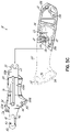
- FIG. 6 is a left side view of another embodiment of knife according to the invention.
- FIG. 7 is a front top left perspective view of the knife of FIG. 6 with the liner plate and the lock lever attached to the first portion of the handle, the fitment plate attached to the second portion of the handle, and the second portion of the handle shown removed from the first portion of the handle.
- FIG. 8 is a rear top right perspective view of the knife of FIG. 6 with the liner plate and the lock lever attached to the first portion of the handle, the fitment plate attached to the second portion of the handle, and the second portion of the handle shown removed from the first portion of the handle.
- FIG. 9 is a top cross-sectional view of the knife blade and knife handle of FIG. 6 .
- FIG. 10A is a right side partial cross-sectional view of the knife blade and knife handle of FIG. 6 .
- FIG. 10B is a view similar to FIG. 10A with the knife blade removed.
- FIG. 10C is a view similar to FIG. 10B with certain details omitted for clarity.
- FIG. 11 is a right side view of various blades usable with the invention.
- FIG. 12 is a right side view of various additional blades usable with the invention.
- FIG. 1 there is illustrated a knife 10 forming a part of the cutlery system of the present invention.
- the knife 10 has a blade 12 (a filet blade in these figures) and a handle 14 .
- handle 14 has a first portion 19 , a second portion 21 , and a third portion 22 .
- First portion 19 forms a left-hand half of handle 14
- second and third portions 21 , 22 combine to form a right-hand half of handle 14 .
- Screws 21 a secure handle second portion 21 to handle first portion 19 .
- Handle portion 22 can be removed from handle portion 19 for cleaning and the like, as described below.
- Handle portions 19 , 21 and 22 can be fabricated of, for example, injection molded nylon, and can include various decorative and/or grip inserts epoxy bonded thereto.
- the handle second portion 21 has a pivoting locking lever 24 fabricated of, for example, injection molded nylon.
- Locking lever 24 carries a lever lock 26 fabricated of, for example, stainless steel. Locking lever 24 rotates in a relief area on an outerside of handle second portion 21 . See FIG. 3B . Locking lever 24 rotates the lever lock 26 in a semi-circular, greater than 180 degrees, notch 28 of a fitment plate 30 fabricated of, for example, stainless steel. Fitment plate 30 is screwed to the third handle portion 22 with screws 22 a . Rotation of locking lever 24 rotates lever lock 26 to lock and unlock the third handle portion 22 to and from, respectively, the first handle portion 19 .
- the lever lock 26 has a pair of opposed straight sides 27 and a pair of opposed semi-circular sides 29 .
- the lever lock 26 can be completely received in notch 28 . Once received in the notch 28 , the lever lock 26 can be rotated by locking lever 24 to lock the third handle portion 22 to the first handle portion 19 . See FIGS. 5B and 5C .
- Fitment plate 30 has a spring 32 screwed thereto and is fabricated of, for example, stainless steel, and is in the form of a cantilever beam or leaf spring.
- Spring 32 has a spring stud 34 that cooperates with a release button 36 .
- Release button 36 is biased away from, i.e. out of contact with, leaf spring 32 via a compression spring 35 .
- Knife blade 12 has an elongated slot 38 in a proximal end thereof.
- the slot 38 has a wider proximal portion 37 and a narrower distal portion 39 .
- the fitment plate 30 has an extension 40 that extends or projects outwardly from a distal end of the handle 14 .
- the extension 40 has an elongated oval protuberance, nub, or lug 42 that is closely and slidably received in the slot 38 .
- the protuberance 42 includes a first portion 41 which can pass through the wider proximal portion 37 of the slot 38 but which cannot pass through the narrower distal portion 39 of the slot 38 , and a second portion 43 , narrower than the first portion 41 , that connects the first portion 41 to the plate 30 and which is closely and slidably received in the narrower distal portion 39 of the slot 38 .
- the fitment plate 30 has a fitment stud 44 fabricated of, for example, stainless steel, that is received in a recess 46 in blade 12 .
- Portion 20 of first handle portion 19 of handle 14 has a liner plate 50 fabricated of, for example, stainless steel, screwed to it at a distal end thereof with screws 20 a .
- Liner plate 50 has notches 52 , 54 that receive tangs 56 , 58 , respectively, on fitment plate 30 .
- the lever lock 26 , notch 28 , tangs 56 , 58 , and notches 52 , 54 serve to securely removably attach second portion 22 of handle 14 to first portion 19 of handle 14 .
- handle portion 22 is slid into/onto handle portion 19 and locked via the locking lever 24 .
- the proximal end of the blade 12 is inserted into the distal end of the handle 14 .
- Sliding the proximal end of the blade 12 into the handle 14 while pressing the release button 36 to deflect the spring 32 permits the blade 12 to be fully inserted into the handle 14 .
- the release button 36 can be released, whereupon the spring 32 biases the spring stud 34 into the elongated slot 38 .
- the release button 36 is pressed which deflects the spring 32 and thereby moves the spring stud 34 out of the elongated slot 38 in the blade 12 .
- the proximal end of said blade 12 can be slid out of the handle 14 to thereby detach the blade 12 from said handle 14 .
- blades can be used to form the cutlery system of the invention.
- the system can include blades such as filet knife blades, clip or clip point knife blades, gut hook knife blades, and saw blades, including a plurality of lengths of each.
- FIG. 6 there is illustrated another knife 110 forming a part of the cutlery system of the present invention.
- the knife 110 has a blade 112 (a filet blade in these figures) and a handle 114 .
- handle 114 has a first portion 120 and a second portion 122 removably secured to the first portion 201 .
- Handle portions 120 and 122 can be fabricated of, for example, injection molded nylon, and can include various decorative and/or grip inserts epoxy bonded thereto.
- the first portion 120 has a pivoting locking lever 124 fabricated of, for example, injection molded nylon, that carries a lever lock 126 fabricated of, for example, stainless steel, that moves into and out of a notch 128 of a fitment plate 130 fabricated of, for example, stainless steel, screwed to the second portion 122 , to lock and unlock the second portion 122 to and from, respectively, the first portion 120 .
- Fitment plate 130 has a spring 132 screwed thereto and is fabricated of, for example, stainless steel, and is in the form of a cantilever beam.
- Spring 132 has a spring stud 134 and a release button 136 .
- Knife blade 112 has an elongated slot 138 in a proximal end thereof.
- the fitment plate 130 has an extension 140 that extends or projects outwardly from a distal end of the handle 114 .
- the extension 140 has an elongated oval protuberance, nub, or lug 142 that is closely and slidably received in the slot 138 .
- the fitment plate 130 has a fitment stud 144 fabricated of, for example, stainless steel, that is received in a recess 146 in blade 112 .
- First portion 120 of handle 114 has a liner plate 150 fabricated of, for example, stainless steel, screwed to it at a distal end thereof.
- Liner plate 150 has notches 152 , 154 that receive tangs 156 , 158 , respectively, on fitment plate 130 .
- the lever lock 126 , notch 128 , tangs 156 , 158 , and notches 152 , 154 serve to securely removably attach second portion 122 of handle 114 to first portion 120 of handle 114 .
- the proximal end of the blade 112 is inserted into the distal end of the handle 114 .
- the spring 138 is deflected by virtue of the proximal end of the blade 112 acting upon the spring stud 134 , and/or by pressing the release button 136 . Insertion of the blade 112 into the handle 114 continues until such time as the proximal end of the elongated slot 138 clears the spring stud 134 , whereupon the spring 132 biases the spring stud 134 into the elongated slot 138 .
- the fitment stud 144 is firmly received in the recess 146 of the blade 112
- the distal end of the lug 142 is firmly received in the distal end of the elongated slot 138 .
- the release button 136 is pressed which deflects the spring 132 and thereby moves the spring stud 134 out of the elongated slot 138 in the blade 112 .
- the proximal end of said blade 112 can be slid out of the handle 114 to thereby detach the blade 112 from said handle 114 .
- FIG. 11 illustrates several knife blades that can be used to form the cutlery system of the invention.
- the system can include filet blades 160 , clip or clip point blades 170 , and gut hook blades 180 , and including a plurality of lengths of each.
- the cutlery system of the present invention is a platform whereby numerous blade styles and tools can be utilized.
- Other implements that can be utilized with this system are fish scalers 194 , back-serrated fillet blades 190 , large bush craft blades 196 , saws 192 , etc., as shown in FIG. 12 .
- the implements shown in FIG. 12 are well known in the art.
Landscapes
- Life Sciences & Earth Sciences (AREA)
- Forests & Forestry (AREA)
- Engineering & Computer Science (AREA)
- Mechanical Engineering (AREA)
- Knives (AREA)
Abstract
Description
Claims (9)
Priority Applications (2)
| Application Number | Priority Date | Filing Date | Title |
|---|---|---|---|
| US16/244,266 US11370132B2 (en) | 2018-01-10 | 2019-01-10 | Interchangeable cutlery system |
| US17/663,615 US12076875B2 (en) | 2018-01-10 | 2022-05-16 | Interchangeable cutlery system |
Applications Claiming Priority (3)
| Application Number | Priority Date | Filing Date | Title |
|---|---|---|---|
| US201862615693P | 2018-01-10 | 2018-01-10 | |
| US201862632092P | 2018-02-19 | 2018-02-19 | |
| US16/244,266 US11370132B2 (en) | 2018-01-10 | 2019-01-10 | Interchangeable cutlery system |
Related Child Applications (1)
| Application Number | Title | Priority Date | Filing Date |
|---|---|---|---|
| US17/663,615 Division US12076875B2 (en) | 2018-01-10 | 2022-05-16 | Interchangeable cutlery system |
Publications (2)
| Publication Number | Publication Date |
|---|---|
| US20190210232A1 US20190210232A1 (en) | 2019-07-11 |
| US11370132B2 true US11370132B2 (en) | 2022-06-28 |
Family
ID=67140385
Family Applications (2)
| Application Number | Title | Priority Date | Filing Date |
|---|---|---|---|
| US16/244,266 Active US11370132B2 (en) | 2018-01-10 | 2019-01-10 | Interchangeable cutlery system |
| US17/663,615 Active US12076875B2 (en) | 2018-01-10 | 2022-05-16 | Interchangeable cutlery system |
Family Applications After (1)
| Application Number | Title | Priority Date | Filing Date |
|---|---|---|---|
| US17/663,615 Active US12076875B2 (en) | 2018-01-10 | 2022-05-16 | Interchangeable cutlery system |
Country Status (2)
| Country | Link |
|---|---|
| US (2) | US11370132B2 (en) |
| CA (1) | CA3029670A1 (en) |
Cited By (10)
| Publication number | Priority date | Publication date | Assignee | Title |
|---|---|---|---|---|
| US20220118537A1 (en) * | 2011-08-04 | 2022-04-21 | Milwaukee Electric Tool Corporation | Reciprocating saw blade |
| US20220241954A1 (en) * | 2021-01-29 | 2022-08-04 | Jiminox Limited | Handle of assembly tool with an adjustable center of gravity |
| US20220388185A1 (en) * | 2019-11-07 | 2022-12-08 | 3D Holding Company, Llc | Hunting knife and scalpel with interchangeable blades |
| US11642801B1 (en) * | 2022-07-01 | 2023-05-09 | Darex, Llc | Utility blades and combination blade holders |
| US20240009871A1 (en) * | 2022-07-07 | 2024-01-11 | Stanley Payne | Knife Set With Replacement Blades |
| USD1013093S1 (en) * | 2020-01-10 | 2024-01-30 | Aob Products Company | Handle unit of an interchangeable blade knife |
| US11969909B2 (en) | 2022-07-01 | 2024-04-30 | Darex, Llc | Utility blades and combination blade holders |
| US12030203B2 (en) | 2019-06-17 | 2024-07-09 | Aob Products Company | Knife having removable blade |
| US12076875B2 (en) | 2018-01-10 | 2024-09-03 | Havel's Inc. | Interchangeable cutlery system |
| US12330324B2 (en) * | 2022-07-13 | 2025-06-17 | Huan Zhang | Folding knife containing blade replacement structure |
Families Citing this family (2)
| Publication number | Priority date | Publication date | Assignee | Title |
|---|---|---|---|---|
| US20240066727A1 (en) * | 2022-08-26 | 2024-02-29 | Jacob Michael Helzer | Utility knife with built-in fire starter kit |
| USD1110820S1 (en) * | 2023-10-31 | 2026-02-03 | Aob Products Company | Knife blade |
Citations (39)
| Publication number | Priority date | Publication date | Assignee | Title |
|---|---|---|---|---|
| US3863339A (en) * | 1972-05-26 | 1975-02-04 | Stanley Tools Ltd | Retractable blade knife |
| US3900950A (en) * | 1974-03-18 | 1975-08-26 | Walter W Collins | Knife with removable blade |
| US3924493A (en) * | 1974-10-21 | 1975-12-09 | John Penner | Quick release extension shaft for socket wrenches |
| US4233737A (en) * | 1979-04-13 | 1980-11-18 | Poehlmann Paul W | Knife with removable blade |
| US4292738A (en) * | 1979-01-20 | 1981-10-06 | Kai Cutlery Center Co., Ltd. | Knife |
| US5774994A (en) * | 1996-07-29 | 1998-07-07 | Ekco Housewares, Inc. | Collapsible barbecue tools |
| US5862596A (en) * | 1997-06-09 | 1999-01-26 | Chung; Yen-Chao | Hand held cutter |
| US6055733A (en) * | 1999-05-03 | 2000-05-02 | Chen; Yih-Long | Extensible cutlery device |
| US6085424A (en) * | 1999-04-07 | 2000-07-11 | Mai; Hsiao-Feng | Hand tool having a handle provided with means for fastening detachably the handle with a blade |
| US6336731B1 (en) * | 2000-08-03 | 2002-01-08 | Kuo-Huei Chien | Field multi-use tool structure |
| US6367854B1 (en) * | 2000-02-29 | 2002-04-09 | Chou Hwei-Rung | Handle device of an impact hand tool |
| US20030024126A1 (en) * | 2001-08-03 | 2003-02-06 | Te-Ching Liu | Snap-assembling structure of a grip for grill tools |
| US6675483B2 (en) * | 2001-11-29 | 2004-01-13 | Helman Group, Ltd. | Combination barbecue tool |
| US6694578B1 (en) * | 2003-05-15 | 2004-02-24 | Kimberly A. Nicoll | Child safety belt buckle locking mechanism |
| US20050252010A1 (en) * | 2004-05-17 | 2005-11-17 | Fiskars Brands, Inc. | Exchangeable blade knife |
| US20060053639A1 (en) * | 2004-09-14 | 2006-03-16 | Nakanishi Inc. | Replacement blade and holder for reciprocating saw |
| US20060117570A1 (en) * | 2004-12-07 | 2006-06-08 | Pool Dan B | Utility Knife with Cam Clamp Means |
| US20070044323A1 (en) * | 2005-08-30 | 2007-03-01 | Walley Chao | Cutter having detachable cutter blade |
| US20070204471A1 (en) * | 2006-03-02 | 2007-09-06 | Castagna Matthew I | Knife with disposable and interchangeable blade |
| US20070256310A1 (en) * | 2006-05-02 | 2007-11-08 | Pool Dan B | Utility Knife With Cam Clamping Means |
| US20080276468A1 (en) * | 2004-09-30 | 2008-11-13 | Mora Of Sweden | Knife |
| US20090217536A1 (en) * | 2008-02-29 | 2009-09-03 | Simon Medhurst | Hand tool with interchangeable tool elements |
| US7621051B2 (en) * | 2004-03-19 | 2009-11-24 | Great Neck Saw Manufacturers, Inc. | Utility knife |
| US20100107424A1 (en) * | 2008-10-14 | 2010-05-06 | Michael Garcia | Blade release mechanisms for utility knives |
| US20100192382A1 (en) * | 2009-02-05 | 2010-08-05 | Wade Burch | Hand saw |
| US20100263219A1 (en) * | 2008-12-17 | 2010-10-21 | Kempker Jeffrey A | Tool with ergonomic handle and replaceable cutter head |
| US20110030225A1 (en) * | 2009-08-10 | 2011-02-10 | Desheng Wang | Press-down type composite putty knife |
| US20120073142A1 (en) * | 2010-09-24 | 2012-03-29 | Zeng min-zheng | Cutting Apparatus |
| US8191267B2 (en) * | 2007-12-28 | 2012-06-05 | United States Gypsum Company | Tool with replaceable blade |
| US8205341B2 (en) * | 2007-10-01 | 2012-06-26 | United States Gypsum Company | Tool with replaceable blade |
| US8419510B2 (en) * | 2009-08-10 | 2013-04-16 | Dexter-Russell, Inc. | Poultry deboning knife |
| US8567072B2 (en) * | 2010-06-28 | 2013-10-29 | Medipurpose Pte Ltd | Safety scalpel |
| US20140345147A1 (en) * | 2013-03-15 | 2014-11-27 | Spencer Frazer | Exchange mechanism for knife |
| US20170225353A1 (en) * | 2016-02-10 | 2017-08-10 | Compass Corp. | Quick change woodworking spade bit |
| US20170348863A1 (en) | 2016-06-03 | 2017-12-07 | Browning | Knife apparatus with interchangeable blades |
| USD847938S1 (en) * | 2018-01-10 | 2019-05-07 | Havel's Inc. | Knife handle |
| US20190176349A1 (en) * | 2009-03-04 | 2019-06-13 | Stanley Black & Decker, Inc. | Utility knife |
| US10464223B2 (en) * | 2016-03-15 | 2019-11-05 | Dominick Scalise | Knife and method |
| US20200101633A1 (en) * | 2016-12-20 | 2020-04-02 | Walter HALUCHA | Sliding scale release for an automatically opening tool |
Family Cites Families (6)
| Publication number | Priority date | Publication date | Assignee | Title |
|---|---|---|---|---|
| US12036687B2 (en) * | 2016-12-20 | 2024-07-16 | Latama Llc | Lockable tool with sliding scale release |
| CA3029670A1 (en) | 2018-01-10 | 2019-07-10 | Havel's Inc. | Interchangeable cutlery system |
| US12030203B2 (en) * | 2019-06-17 | 2024-07-09 | Aob Products Company | Knife having removable blade |
| US20230001591A1 (en) * | 2021-07-01 | 2023-01-05 | Mike H. Okamura | Knife with replaceable blade |
| US12370703B2 (en) * | 2021-12-08 | 2025-07-29 | Hogue Tool & Machine, Inc. | Replaceable blade knife |
| KR102534937B1 (en) * | 2022-02-11 | 2023-05-26 | 한아툴스 (주) | Hand grip for tools |
-
2019
- 2019-01-10 CA CA3029670A patent/CA3029670A1/en active Pending
- 2019-01-10 US US16/244,266 patent/US11370132B2/en active Active
-
2022
- 2022-05-16 US US17/663,615 patent/US12076875B2/en active Active
Patent Citations (39)
| Publication number | Priority date | Publication date | Assignee | Title |
|---|---|---|---|---|
| US3863339A (en) * | 1972-05-26 | 1975-02-04 | Stanley Tools Ltd | Retractable blade knife |
| US3900950A (en) * | 1974-03-18 | 1975-08-26 | Walter W Collins | Knife with removable blade |
| US3924493A (en) * | 1974-10-21 | 1975-12-09 | John Penner | Quick release extension shaft for socket wrenches |
| US4292738A (en) * | 1979-01-20 | 1981-10-06 | Kai Cutlery Center Co., Ltd. | Knife |
| US4233737A (en) * | 1979-04-13 | 1980-11-18 | Poehlmann Paul W | Knife with removable blade |
| US5774994A (en) * | 1996-07-29 | 1998-07-07 | Ekco Housewares, Inc. | Collapsible barbecue tools |
| US5862596A (en) * | 1997-06-09 | 1999-01-26 | Chung; Yen-Chao | Hand held cutter |
| US6085424A (en) * | 1999-04-07 | 2000-07-11 | Mai; Hsiao-Feng | Hand tool having a handle provided with means for fastening detachably the handle with a blade |
| US6055733A (en) * | 1999-05-03 | 2000-05-02 | Chen; Yih-Long | Extensible cutlery device |
| US6367854B1 (en) * | 2000-02-29 | 2002-04-09 | Chou Hwei-Rung | Handle device of an impact hand tool |
| US6336731B1 (en) * | 2000-08-03 | 2002-01-08 | Kuo-Huei Chien | Field multi-use tool structure |
| US20030024126A1 (en) * | 2001-08-03 | 2003-02-06 | Te-Ching Liu | Snap-assembling structure of a grip for grill tools |
| US6675483B2 (en) * | 2001-11-29 | 2004-01-13 | Helman Group, Ltd. | Combination barbecue tool |
| US6694578B1 (en) * | 2003-05-15 | 2004-02-24 | Kimberly A. Nicoll | Child safety belt buckle locking mechanism |
| US7621051B2 (en) * | 2004-03-19 | 2009-11-24 | Great Neck Saw Manufacturers, Inc. | Utility knife |
| US20050252010A1 (en) * | 2004-05-17 | 2005-11-17 | Fiskars Brands, Inc. | Exchangeable blade knife |
| US20060053639A1 (en) * | 2004-09-14 | 2006-03-16 | Nakanishi Inc. | Replacement blade and holder for reciprocating saw |
| US20080276468A1 (en) * | 2004-09-30 | 2008-11-13 | Mora Of Sweden | Knife |
| US20060117570A1 (en) * | 2004-12-07 | 2006-06-08 | Pool Dan B | Utility Knife with Cam Clamp Means |
| US20070044323A1 (en) * | 2005-08-30 | 2007-03-01 | Walley Chao | Cutter having detachable cutter blade |
| US20070204471A1 (en) * | 2006-03-02 | 2007-09-06 | Castagna Matthew I | Knife with disposable and interchangeable blade |
| US20070256310A1 (en) * | 2006-05-02 | 2007-11-08 | Pool Dan B | Utility Knife With Cam Clamping Means |
| US8205341B2 (en) * | 2007-10-01 | 2012-06-26 | United States Gypsum Company | Tool with replaceable blade |
| US8191267B2 (en) * | 2007-12-28 | 2012-06-05 | United States Gypsum Company | Tool with replaceable blade |
| US20090217536A1 (en) * | 2008-02-29 | 2009-09-03 | Simon Medhurst | Hand tool with interchangeable tool elements |
| US20100107424A1 (en) * | 2008-10-14 | 2010-05-06 | Michael Garcia | Blade release mechanisms for utility knives |
| US20100263219A1 (en) * | 2008-12-17 | 2010-10-21 | Kempker Jeffrey A | Tool with ergonomic handle and replaceable cutter head |
| US20100192382A1 (en) * | 2009-02-05 | 2010-08-05 | Wade Burch | Hand saw |
| US20190176349A1 (en) * | 2009-03-04 | 2019-06-13 | Stanley Black & Decker, Inc. | Utility knife |
| US20110030225A1 (en) * | 2009-08-10 | 2011-02-10 | Desheng Wang | Press-down type composite putty knife |
| US8419510B2 (en) * | 2009-08-10 | 2013-04-16 | Dexter-Russell, Inc. | Poultry deboning knife |
| US8567072B2 (en) * | 2010-06-28 | 2013-10-29 | Medipurpose Pte Ltd | Safety scalpel |
| US20120073142A1 (en) * | 2010-09-24 | 2012-03-29 | Zeng min-zheng | Cutting Apparatus |
| US20140345147A1 (en) * | 2013-03-15 | 2014-11-27 | Spencer Frazer | Exchange mechanism for knife |
| US20170225353A1 (en) * | 2016-02-10 | 2017-08-10 | Compass Corp. | Quick change woodworking spade bit |
| US10464223B2 (en) * | 2016-03-15 | 2019-11-05 | Dominick Scalise | Knife and method |
| US20170348863A1 (en) | 2016-06-03 | 2017-12-07 | Browning | Knife apparatus with interchangeable blades |
| US20200101633A1 (en) * | 2016-12-20 | 2020-04-02 | Walter HALUCHA | Sliding scale release for an automatically opening tool |
| USD847938S1 (en) * | 2018-01-10 | 2019-05-07 | Havel's Inc. | Knife handle |
Non-Patent Citations (3)
| Title |
|---|
| Browning Speed Load Knives, in public use and on sale in the US more than one year prior to Jan. 10, 2019, 6 pages. |
| Havalon Hydra Red, in public use and on sale in the US more than one year prior to Jan. 10, 2019, 9 pages. |
| Havel's Blades and Accessories, in public use and on sale in the US more than one year prior to Jan. 10, 2019, 3 pages. |
Cited By (14)
| Publication number | Priority date | Publication date | Assignee | Title |
|---|---|---|---|---|
| US12202064B2 (en) * | 2011-08-04 | 2025-01-21 | Milwaukee Electric Tool Corporation | Reciprocating saw blade |
| US20220118537A1 (en) * | 2011-08-04 | 2022-04-21 | Milwaukee Electric Tool Corporation | Reciprocating saw blade |
| US12076875B2 (en) | 2018-01-10 | 2024-09-03 | Havel's Inc. | Interchangeable cutlery system |
| US12441011B2 (en) | 2019-06-17 | 2025-10-14 | Aob Products Company | Knife having removable blade |
| US12285879B2 (en) | 2019-06-17 | 2025-04-29 | Aob Products Company | Knife having removable blade |
| US12030203B2 (en) | 2019-06-17 | 2024-07-09 | Aob Products Company | Knife having removable blade |
| US20220388185A1 (en) * | 2019-11-07 | 2022-12-08 | 3D Holding Company, Llc | Hunting knife and scalpel with interchangeable blades |
| USD1013093S1 (en) * | 2020-01-10 | 2024-01-30 | Aob Products Company | Handle unit of an interchangeable blade knife |
| US20220241954A1 (en) * | 2021-01-29 | 2022-08-04 | Jiminox Limited | Handle of assembly tool with an adjustable center of gravity |
| US12076847B2 (en) * | 2021-01-29 | 2024-09-03 | Jiminox Limited | Handle of assembly tool with an adjustable center of gravity |
| US11642801B1 (en) * | 2022-07-01 | 2023-05-09 | Darex, Llc | Utility blades and combination blade holders |
| US11969909B2 (en) | 2022-07-01 | 2024-04-30 | Darex, Llc | Utility blades and combination blade holders |
| US20240009871A1 (en) * | 2022-07-07 | 2024-01-11 | Stanley Payne | Knife Set With Replacement Blades |
| US12330324B2 (en) * | 2022-07-13 | 2025-06-17 | Huan Zhang | Folding knife containing blade replacement structure |
Also Published As
| Publication number | Publication date |
|---|---|
| US20190210232A1 (en) | 2019-07-11 |
| US20220388187A1 (en) | 2022-12-08 |
| CA3029670A1 (en) | 2019-07-10 |
| US12076875B2 (en) | 2024-09-03 |
Similar Documents
| Publication | Publication Date | Title |
|---|---|---|
| US12076875B2 (en) | Interchangeable cutlery system | |
| US20230049878A1 (en) | Knife with replaceable blade | |
| US6574868B1 (en) | Knife with replaceable cutting element | |
| US5689889A (en) | Knife with replaceable cutting element | |
| US10144139B2 (en) | Utility knife | |
| US6058611A (en) | Reversible blade knife | |
| US9687987B2 (en) | Folding knife with replaceable blade | |
| US11305440B2 (en) | Knife with interchangeable blade | |
| US6698099B2 (en) | Convertible knife | |
| US2800096A (en) | Tufter hook | |
| US20040250426A1 (en) | Utility knife | |
| US1813723A (en) | Knife | |
| US20220388185A1 (en) | Hunting knife and scalpel with interchangeable blades | |
| US20080250652A1 (en) | Self locking knife and sheath | |
| US20090307911A1 (en) | Cutting Tool | |
| US20240316802A1 (en) | Knife having removable blade | |
| US20160184999A1 (en) | Utility knife with pivoting head assembly | |
| US20070204471A1 (en) | Knife with disposable and interchangeable blade | |
| US4651419A (en) | Double ended single blade knife | |
| US1448305A (en) | Interchangeable-blade-operating knife | |
| US20200276723A1 (en) | Trimsafe histology radius blade grossing knife | |
| US7533466B2 (en) | Folding tool with lock | |
| US5157837A (en) | Cutting implement | |
| CN103763918A (en) | Improved line cutter for fishing rods | |
| US4712546A (en) | Cutting instrument for nasal surgery which cuts parallel to its length |
Legal Events
| Date | Code | Title | Description |
|---|---|---|---|
| FEPP | Fee payment procedure |
Free format text: ENTITY STATUS SET TO UNDISCOUNTED (ORIGINAL EVENT CODE: BIG.); ENTITY STATUS OF PATENT OWNER: SMALL ENTITY |
|
| FEPP | Fee payment procedure |
Free format text: ENTITY STATUS SET TO SMALL (ORIGINAL EVENT CODE: SMAL); ENTITY STATUS OF PATENT OWNER: SMALL ENTITY |
|
| STPP | Information on status: patent application and granting procedure in general |
Free format text: NON FINAL ACTION MAILED |
|
| AS | Assignment |
Owner name: HAVEL'S, LLC, OHIO Free format text: ASSIGNMENT OF ASSIGNORS INTEREST;ASSIGNOR:TSAI, WU HSIEN;REEL/FRAME:052721/0447 Effective date: 20200514 |
|
| AS | Assignment |
Owner name: HAVEL'S, LLC, OHIO Free format text: ASSIGNMENT OF ASSIGNORS INTEREST;ASSIGNOR:HAVEL'S, LLC;REEL/FRAME:052757/0492 Effective date: 20200515 Owner name: GIGAND COMPANY, LTD, TAIWAN Free format text: ASSIGNMENT OF ASSIGNORS INTEREST;ASSIGNOR:HAVEL'S, LLC;REEL/FRAME:052757/0492 Effective date: 20200515 |
|
| STPP | Information on status: patent application and granting procedure in general |
Free format text: RESPONSE TO NON-FINAL OFFICE ACTION ENTERED AND FORWARDED TO EXAMINER |
|
| STPP | Information on status: patent application and granting procedure in general |
Free format text: NON FINAL ACTION MAILED |
|
| STPP | Information on status: patent application and granting procedure in general |
Free format text: RESPONSE TO NON-FINAL OFFICE ACTION ENTERED AND FORWARDED TO EXAMINER |
|
| STPP | Information on status: patent application and granting procedure in general |
Free format text: FINAL REJECTION MAILED |
|
| STPP | Information on status: patent application and granting procedure in general |
Free format text: DOCKETED NEW CASE - READY FOR EXAMINATION |
|
| STPP | Information on status: patent application and granting procedure in general |
Free format text: NOTICE OF ALLOWANCE MAILED -- APPLICATION RECEIVED IN OFFICE OF PUBLICATIONS |
|
| STPP | Information on status: patent application and granting procedure in general |
Free format text: NOTICE OF ALLOWANCE MAILED -- APPLICATION RECEIVED IN OFFICE OF PUBLICATIONS |
|
| STPP | Information on status: patent application and granting procedure in general |
Free format text: PUBLICATIONS -- ISSUE FEE PAYMENT VERIFIED |
|
| STCF | Information on status: patent grant |
Free format text: PATENTED CASE |
|
| CC | Certificate of correction | ||
| MAFP | Maintenance fee payment |
Free format text: PAYMENT OF MAINTENANCE FEE, 4TH YR, SMALL ENTITY (ORIGINAL EVENT CODE: M2551); ENTITY STATUS OF PATENT OWNER: SMALL ENTITY Year of fee payment: 4 |