US1136816A - Apparatus for drawing sheet-glass. - Google Patents
Apparatus for drawing sheet-glass. Download PDFInfo
- Publication number
- US1136816A US1136816A US81283414A US1914812834A US1136816A US 1136816 A US1136816 A US 1136816A US 81283414 A US81283414 A US 81283414A US 1914812834 A US1914812834 A US 1914812834A US 1136816 A US1136816 A US 1136816A
- Authority
- US
- United States
- Prior art keywords
- sheet
- glass
- rolls
- shaft
- drawn
- Prior art date
- Legal status (The legal status is an assumption and is not a legal conclusion. Google has not performed a legal analysis and makes no representation as to the accuracy of the status listed.)
- Expired - Lifetime
Links
Images


Classifications
-
- C—CHEMISTRY; METALLURGY
- C03—GLASS; MINERAL OR SLAG WOOL
- C03B—MANUFACTURE, SHAPING, OR SUPPLEMENTARY PROCESSES
- C03B15/00—Drawing glass upwardly from the melt
- C03B15/18—Means for laying-down and conveying combined with the drawing of glass sheets, tubes or rods
Definitions
- This invention relates to an apparatus for drawing sheets of glass from a mass of molten glass, and particularly to means for drawing acontinuous sheet of glass ofsubsta'ntially uniform width and thickness, the primary object of the'invention being to provide a novel and improved means 'to act upon the drawn sheet to spread the sheet laterally, thereby overcoming the tendency of the sheet to narrow as it is drawn out.
- a further object of theinvention is to provide an apparatus for insuri g the positive feed of the sheet of glass an spreading it .in the manner described in a uniform manner, so that a sh'eet which is substantially uniform in width and thickness may be continuously drawn.
- a still further object of the invention is to provide a spreading mechanism which is simple of construction, reliable and efficient in action, which embodies means forgcooling the same to prevent undue heating thereof, andwhich is adjustable to vary the character of the lateral spreading action a well as to dispose the spreading devices asjocca- .sion' may require above the tank or neceptacle containing the mass of molten g1 ss.
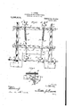
- FIG. 1 is a vertical transverse section through a portion ofa glass drawing apparatus embodying my invention.
- Fig. 2 1s a side elevationof the same.
- Fig. 3 is a vertical longitudinal section.
- Fig. l is a top plan view.
- Figs. 5 and 6 are detail longitudinal and transverse sections on the lines- 5-5 and 6-6 of Fig. 4 through parts of the frame of the spreading devices.
- I Figs/7 and- 8 are diagrammatic eleva-tional views illustrating different positions and spreading actions of the spreading rollers.
- 1 designates a ank' or other suitable receptacle, in wh ch scontained the body2 of molten glass,- from vhich the glass in sheetform is to be dra n.
- tank or receptacle may be heated in any known or approved manner.
- the tank or receptacle may be of that type having a contracted mouth or dog-house 3 exposmg a portion of the body of molten glass from which the sheet glass is directly drawn through the medium of a"bait i of suitable construction, operated in any known or suitable manner.
- a glass sheet 5 which is being drawn continuously by. the action of the bait from the mass of molten glass.
- My invention provides a mechanism which is designed to act upon the sheet of glass adjacent the point where it is drawn from the body. of molten glass, to spread the glass laterally in opposite directions as it is drawn out, thus counteracting its narrowing tendency and insuring the production of a continous, sheet of gla-ss of substantially uniform width and thickness throughout;
- the mechanism. designed for this purpose is adapted for use in connection with any ordinary glass drawing apparatus of the. type defined, suflicient only of a known drawing apparatus being shown toclearly illustrate the invention.
- the spreading mechanism comprises a transverse shaft 6 which extends 'over. the mouth or dog-house'3 ofthe tankl and is supported, with the other parts of the spreading mechanism, by a horizontal frame structure comprisinga pair of longitudinal beams 7 and a pair of transversebeams 8 connected at intervals with said longitudinal beams, At their points of crossing the respective beams 7 and 8 BJIGPIOVldGd wit slots 9 and 10 for the-passage of coupling bolts 11', the construction thus being such that the beams 7 may beadjusted "with rela- 30 heated to an excessive degree from the glass.
- the beams 8- are adjustable as described, the beams 8- are preferably fixed to a base or foundation or to the frame work of the glass drawing apparatus.
- the shaft 6 is journaled in bearing brackets 12 carried bythe adjacent ends of the-beams 7, and on said shaft 6- are mounted hollow guide rolls 13 which are fixed to the shaft to rotate therewith and are properly spaced to bear upon one side of the sheet adjacent to the side edges thereof, and but a short distance above the surface of the body of molten glass from which the sheet is drawn.
- the shafts and 15 and rolls 13 and are hollow, the. respective rolls being in communication with their respective shafts in such manner that water may be-circu- -lated therethrough to cool the shafts and rolls and prevent the same from being
- Each shaft 6 and 15 is'hollow and inclos'es a water feeder supply pipe 18, and the respective pipes 18 connect with suitable spray or discharge devices 19 arranged within the hollow rolls'13 and 14,'by which cooling water is supplied thereto, the water flowing .back and' discharging through the'pipes 6 and 15, as will be readily understood.
- Valves 20 are provided in the pipes 18 to control the supply of the coolin 7 are provided with slots 22, through which slots pass bolts 23, whereby the brackets are secured in position and may be vertically or longitudinally adjusted to support the 1 pipe 6- atdifferent elevations or ,at different positions over the -mouth of the melt ng tank.
- the brackets 16 are similarly provided with slots 2 1and the beams 8 with slots 25, through which slots pass coupling bolts 26 securing the brackets to the beams, the connection being such that the bracket may be vertically adjusted or adjusi ":d in a direction transversely of the frame, as 'will bereadily understood.
- the bearing brackets 12 are provi ed with" slots 21 and the adjacent ends of the beams "suitable power.
- a coiled spring 27' is providedfor sliding each shaft 15 forwardly. and holding the as. sociated roll-14; with the required pressure in contact with-the drawn sheet.- One end of this spring bearsagainst one of the'rear brackets' 16 or any other suitable abutment and the other end'of the spring is arranged to bear against an adjustable" abutment comprising a collar 28 secured to the shaft by .a set screw 29, whereby the tension of, the
- the rolls 14 may be disposed so that their axes will be below the planeof the shaft-'6, and" so that "8.13 proximately one-half ofeach roll will be arranged beyond the edge of thelsheet and the other halfofthe roll in position to engage: the sheet, as shown in-Fig. 7 so that on re tating'the rolls inan inward and-upward direction, as indicated by the arrows a shown in said Fig.
- spreader rollers carried by said shaft in line with'the guide rollers'and arranged to bear against the opposite face of the sheet and to laterally spread the same to maintain uni- ,form Width thereof, means for adjusting the second-named shafts to vary the relation-' means for adjusting said pair of rotary shafts in a vertical direction and horizontally toward or from each other, spread form Width thereof, and means a rotary shaft, guide rollers carriedrollers carried by 'said shafts in line with the guide rollers and arranged "tobear 15 against the opposite face of the sheet to laterally spread the same'to maintain'a unifor-rotating the respeetive shafts.
Description
L. J. KREBS. APPARATUS FOR DRAWING SHEET GLASS.
APPLICATION FILED JAN. 17, I914.
Patented Apr. 20, 1915.
a SHEBTS-SHEET 1. 4
L. 1. KREBS.
APPARATUS FOR DRAWING SHEET GLASS. APPLICATION FILED 1m. 11, 1914.
1513 31 Patented A r. 20, 1915.
s BHEETFBHBET 2.
' L. .l. KREBS. APPARATUS FOR DRAWING SHEET GLASS.
APPLICATION men JAN. 1?. 1914. Patented Apr. 20
' a snnn'rs snnm' a.
,1 UNITED STA .LOIIIS J. KREBS OF COEFEY-VILLE, Kansas},
APPARATUS non. DRAWING snnE'r-oLAss. A
Specification of Letters Patent. i Patented 20,1915;
Application filed January 17, 1914. Serial No. 812,834.
Toall qohom it may concern:
-Be 1t known that I, Lorns J. Knees, a
citizen of the United States, residing at 'Coffeyville, in the county of Montgomery and State of Kansas, have invented new and useful Improvements in Apparatus for Drawing Sheet-Glass,-'of which the followmg is a specification.
This inventionrelates to an apparatus for drawing sheets of glass from a mass of molten glass, and particularly to means for drawing acontinuous sheet of glass ofsubsta'ntially uniform width and thickness, the primary object of the'invention being to provide a novel and improved means 'to act upon the drawn sheet to spread the sheet laterally, thereby overcoming the tendency of the sheet to narrow as it is drawn out.
A further object of theinvention is to provide an apparatus for insuri g the positive feed of the sheet of glass an spreading it .in the manner described in a uniform manner, so that a sh'eet which is substantially uniform in width and thickness may be continuously drawn.
- A still further object of the invention is to provide a spreading mechanism which is simple of construction, reliable and efficient in action, which embodies means forgcooling the same to prevent undue heating thereof, andwhich is adjustable to vary the character of the lateral spreading action a well as to dispose the spreading devices asjocca- .sion' may require above the tank or neceptacle containing the mass of molten g1 ss.
The invention consists of the featu es of construction, combination and arrangement of parts herein fully described and claimed, reference being had to the accompanying drawings in which I Figure 1 isa vertical transverse section through a portion ofa glass drawing apparatus embodying my invention. Fig. 2 1s a side elevationof the same. Fig. 3 is a vertical longitudinal section. Fig. l is a top plan view. Figs. 5 and 6 are detail longitudinal and transverse sections on the lines- 5-5 and 6-6 of Fig. 4 through parts of the frame of the spreading devices. I Figs/7 and- 8 are diagrammatic eleva-tional views illustrating different positions and spreading actions of the spreading rollers.
-Rferring tothe drawings, 1 designates a ank' or other suitable receptacle, in wh ch scontained the body2 of molten glass,- from vhich the glass in sheetform is to be dra n.
which tank or receptacle may be heated in any known or approved manner. The tank or receptacle may be of that type having a contracted mouth or dog-house 3 exposmg a portion of the body of molten glass from which the sheet glass is directly drawn through the medium of a"bait i of suitable construction, operated in any known or suitable manner. In the drawings I have shown, for the purpose of illustrating the operalIIO II of my invention, a glass sheet 5 which is being drawn continuously by. the action of the bait from the mass of molten glass.
In the operation of drawing sheet glass from aunolten mass by a 'direct drawing actlon, difiiculty is experienced in drawing a sheet of uniform width, since under the drawing action the tendency is to draw the sheet of glass to a narrow rod or thread, the sheet narrowing in its direction of drawing out motion and thus rendering it impossible to producea sheet thickness.
' My invention provides a mechanism which is designed to act upon the sheet of glass adjacent the point where it is drawn from the body. of molten glass, to spread the glass laterally in opposite directions as it is drawn out, thus counteracting its narrowing tendency and insuring the production of a continous, sheet of gla-ss of substantially uniform width and thickness throughout; The mechanism. designed for this purpose is adapted for use in connection with any ordinary glass drawing apparatus of the. type defined, suflicient only of a known drawing apparatus being shown toclearly illustrate the invention.
The spreading mechanism comprises a transverse shaft 6 which extends 'over. the mouth or dog-house'3 ofthe tankl and is supported, with the other parts of the spreading mechanism, by a horizontal frame structure comprisinga pair of longitudinal beams 7 and a pair of transversebeams 8 connected at intervals with said longitudinal beams, At their points of crossing the respective beams 7 and 8 BJIGPIOVldGd wit slots 9 and 10 for the-passage of coupling bolts 11', the construction thus being such that the beams 7 may beadjusted "with rela- 30 heated to an excessive degree from the glass.
are adjustable as described, the beams 8- are preferably fixed to a base or foundation or to the frame work of the glass drawing apparatus. a
As shown, the shaft 6 is journaled in bearing brackets 12 carried bythe adjacent ends of the-beams 7, and on said shaft 6- are mounted hollow guide rolls 13 which are fixed to the shaft to rotate therewith and are properly spaced to bear upon one side of the sheet adjacent to the side edges thereof, and but a short distance above the surface of the body of molten glass from which the sheet is drawn.
Arranged for cooperation with the rolls The shafts and 15 and rolls 13 and are hollow, the. respective rolls being in communication with their respective shafts in such manner that water may be-circu- -lated therethrough to cool the shafts and rolls and prevent the same from being Each shaft 6 and 15 is'hollow and inclos'es a water feeder supply pipe 18, and the respective pipes 18 connect with suitable spray or discharge devices 19 arranged within the hollow rolls'13 and 14,'by which cooling water is supplied thereto, the water flowing .back and' discharging through the'pipes 6 and 15, as will be readily understood. Valves 20 are provided in the pipes 18 to control the supply of the coolin 7 are provided with slots 22, through which slots pass bolts 23, whereby the brackets are secured in position and may be vertically or longitudinally adjusted to support the 1 pipe 6- atdifferent elevations or ,at different positions over the -mouth of the melt ng tank. The brackets 16 are similarly provided with slots 2 1and the beams 8 with slots 25, through which slots pass coupling bolts 26 securing the brackets to the beams, the connection being such that the bracket may be vertically adjusted or adjusi ":d in a direction transversely of the frame, as 'will bereadily understood.
- spreading action on the sheet, thus counteracting its tendency to narrow as it'is drawn out. The shafts 15, in addition to being I water. The bearing brackets 12 are provi ed with" slots 21 and the adjacent ends of the beams "suitable power.
tating the respective shafts. The serrated faces 17 of the rolls 14; are
are also'longitudinally' slidabletherein, and
a coiled spring 27'. is providedfor sliding each shaft 15 forwardly. and holding the as. sociated roll-14; with the required pressure in contact with-the drawn sheet.- One end of this spring bearsagainst one of the'rear brackets' 16 or any other suitable abutment and the other end'of the spring is arranged to bear against an adjustable" abutment comprising a collar 28 secured to the shaft by .a set screw 29, whereby the tension of, the
spring and the pressure of the roller 14' 1 may be regulated. v By adjustably mounting the rollers 13 and 14; in the-manner described, the rolls 14 may be disposed so that their axes will be below the planeof the shaft-'6, and" so that "8.13 proximately one-half ofeach roll will be arranged beyond the edge of thelsheet and the other halfofthe roll in position to engage: the sheet, as shown in-Fig. 7 so that on re tating'the rolls inan inward and-upward direction, as indicated by the arrows a shown in said Fig. 6, a drawingj'and'laterai spreading action will ensue; or the'rolls 1 may be disposed sof'that their axes come above the shaftb and closer to .each other and so that theouter halves of. the. rolls will press the sheet against the-rolls 13, as
shown in Figs. 1 and 8, whereby on rotating the rolls 14 in a-downward and outward directlo'n, as shown by the arrows in said fig ures, a lateral spreading action on the sheet 5 10! will be established. The guiding and spreading rollsmay accordingly be ad usted to suit. varying conditions of service and in action will effectually overcome the tendency of the sheet to narrow as it is drawn outfrom the 4.,
massof molten glass,the reby insuringthe production of a sheet'of substantially form width and thickness It will of course be-.under's tdod, that, in may be driven by any practice, the rolls I claim-: j
1, In an apparatus ,for drawing sheet glass,"a rotary shaft, guiderollerscarried by said shaft to bearagainst one face of the sheet as drawn, alpair of rotary shafts arranged at .an angle to the first-named shaft, spreader rollers carried by said shafts in line with the guide rollers'andarranged to bear against the opposite face of the sheet and to laterally spread the same to maintain a uniform width thereof, and means'for r0;
2. In an apparatus for drawing sheet I glass, a rotary shaft, guide rollers carried.
by said shaft to bear against one face of the .sheet as drawn, a pair of rotary shafts ;ar-' ranged at an angle to-the first-named shaft,
spreader rollers carried by said shaft in line with'the guide rollers'and arranged to bear against the opposite face of the sheet and to laterally spread the same to maintain uni- ,form Width thereof, means for adjusting the second-named shafts to vary the relation-' means for adjusting said pair of rotary shafts in a vertical direction and horizontally toward or from each other, spread form Width thereof, and means a rotary shaft, guide rollers carriedrollers carried by 'said shafts in line with the guide rollers and arranged "tobear 15 against the opposite face of the sheet to laterally spread the same'to maintain'a unifor-rotating the respeetive shafts.
In testimony whereof I afiix in presence of two Witnesses,
LOUIS J. KREBS. Witnesses:
D. M. CAHILL, A. S, NE MAN.
my signature 2o
Priority Applications (1)
| Application Number | Priority Date | Filing Date | Title |
|---|---|---|---|
| US81283414A US1136816A (en) | 1914-01-17 | 1914-01-17 | Apparatus for drawing sheet-glass. |
Applications Claiming Priority (1)
| Application Number | Priority Date | Filing Date | Title |
|---|---|---|---|
| US81283414A US1136816A (en) | 1914-01-17 | 1914-01-17 | Apparatus for drawing sheet-glass. |
Publications (1)
| Publication Number | Publication Date |
|---|---|
| US1136816A true US1136816A (en) | 1915-04-20 |
Family
ID=3204920
Family Applications (1)
| Application Number | Title | Priority Date | Filing Date |
|---|---|---|---|
| US81283414A Expired - Lifetime US1136816A (en) | 1914-01-17 | 1914-01-17 | Apparatus for drawing sheet-glass. |
Country Status (1)
| Country | Link |
|---|---|
| US (1) | US1136816A (en) |
-
1914
- 1914-01-17 US US81283414A patent/US1136816A/en not_active Expired - Lifetime
Similar Documents
| Publication | Publication Date | Title |
|---|---|---|
| US1564240A (en) | Process and apparatus for making sheet glass | |
| CN102471119B (en) | Plate glass manufacturing device and plate glass manufacturing method | |
| US20060010915A1 (en) | Method of continuously producing flat glass by rolling | |
| US1136816A (en) | Apparatus for drawing sheet-glass. | |
| CN100361913C (en) | Method and apparatus for bending and tempering or heat-strengthening a bidirectionally curved glass panel | |
| US1829639A (en) | Method and apparatus for drawing sheet glass | |
| US20190169059A1 (en) | Methods for forming thin glass sheets | |
| US3241521A (en) | Machine for producing smooth coatings | |
| US1554267A (en) | Drawing sheet glass | |
| US2112557A (en) | Process and apparatus for producing mineral wool | |
| US1198044A (en) | Glass drawing and flattenning device. | |
| US1876031A (en) | Apparatus for drawing glass tubings | |
| US1885306A (en) | Conveyer roller | |
| US1639452A (en) | Drawing sheet glass | |
| US965171A (en) | Metal-bending machine. | |
| US1720547A (en) | Method and apparatus for drawing sheet glass | |
| US1519314A (en) | Apparatus for making sheet glass | |
| US1841660A (en) | Width maintaining means for sheet glass apparatus | |
| US1818207A (en) | Process of and apparatus for forming sheet glass | |
| US2140281A (en) | Apparatus for producing sheet glass | |
| US1282163A (en) | Welder. | |
| US1905849A (en) | Method of making sheet glass | |
| US2655765A (en) | Method and apparatus for forming sheet glass | |
| US850548A (en) | Method of coating metal sheets. | |
| US1615840A (en) | Apparatus for making- sheet glass |