US11364693B2 - Method for forming a high-energy density nanocomposite film - Google Patents
Method for forming a high-energy density nanocomposite film Download PDFInfo
- Publication number
- US11364693B2 US11364693B2 US16/807,975 US202016807975A US11364693B2 US 11364693 B2 US11364693 B2 US 11364693B2 US 202016807975 A US202016807975 A US 202016807975A US 11364693 B2 US11364693 B2 US 11364693B2
- Authority
- US
- United States
- Prior art keywords
- high dielectric
- ceramic filler
- dielectric permittivity
- permittivity ceramic
- group
- Prior art date
- Legal status (The legal status is an assumption and is not a legal conclusion. Google has not performed a legal analysis and makes no representation as to the accuracy of the status listed.)
- Expired - Fee Related
Links
Images


Classifications
-
- H—ELECTRICITY
- H01—ELECTRIC ELEMENTS
- H01G—CAPACITORS; CAPACITORS, RECTIFIERS, DETECTORS, SWITCHING DEVICES, LIGHT-SENSITIVE OR TEMPERATURE-SENSITIVE DEVICES OF THE ELECTROLYTIC TYPE
- H01G4/00—Fixed capacitors; Processes of their manufacture
- H01G4/002—Details
- H01G4/018—Dielectrics
- H01G4/06—Solid dielectrics
- H01G4/08—Inorganic dielectrics
- H01G4/12—Ceramic dielectrics
- H01G4/1209—Ceramic dielectrics characterised by the ceramic dielectric material
- H01G4/1218—Ceramic dielectrics characterised by the ceramic dielectric material based on titanium oxides or titanates
- H01G4/1227—Ceramic dielectrics characterised by the ceramic dielectric material based on titanium oxides or titanates based on alkaline earth titanates
-
- B—PERFORMING OPERATIONS; TRANSPORTING
- B29—WORKING OF PLASTICS; WORKING OF SUBSTANCES IN A PLASTIC STATE IN GENERAL
- B29C—SHAPING OR JOINING OF PLASTICS; SHAPING OF MATERIAL IN A PLASTIC STATE, NOT OTHERWISE PROVIDED FOR; AFTER-TREATMENT OF THE SHAPED PRODUCTS, e.g. REPAIRING
- B29C70/00—Shaping composites, i.e. plastics material comprising reinforcements, fillers or preformed parts, e.g. inserts
- B29C70/58—Shaping composites, i.e. plastics material comprising reinforcements, fillers or preformed parts, e.g. inserts comprising fillers only, e.g. particles, powder, beads, flakes, spheres
- B29C70/60—Shaping composites, i.e. plastics material comprising reinforcements, fillers or preformed parts, e.g. inserts comprising fillers only, e.g. particles, powder, beads, flakes, spheres comprising a combination of distinct filler types incorporated in matrix material, forming one or more layers, and with or without non-filled layers
-
- B—PERFORMING OPERATIONS; TRANSPORTING
- B29—WORKING OF PLASTICS; WORKING OF SUBSTANCES IN A PLASTIC STATE IN GENERAL
- B29C—SHAPING OR JOINING OF PLASTICS; SHAPING OF MATERIAL IN A PLASTIC STATE, NOT OTHERWISE PROVIDED FOR; AFTER-TREATMENT OF THE SHAPED PRODUCTS, e.g. REPAIRING
- B29C39/00—Shaping by casting, i.e. introducing the moulding material into a mould or between confining surfaces without significant moulding pressure; Apparatus therefor
- B29C39/003—Shaping by casting, i.e. introducing the moulding material into a mould or between confining surfaces without significant moulding pressure; Apparatus therefor characterised by the choice of material
-
- B—PERFORMING OPERATIONS; TRANSPORTING
- B29—WORKING OF PLASTICS; WORKING OF SUBSTANCES IN A PLASTIC STATE IN GENERAL
- B29C—SHAPING OR JOINING OF PLASTICS; SHAPING OF MATERIAL IN A PLASTIC STATE, NOT OTHERWISE PROVIDED FOR; AFTER-TREATMENT OF THE SHAPED PRODUCTS, e.g. REPAIRING
- B29C39/00—Shaping by casting, i.e. introducing the moulding material into a mould or between confining surfaces without significant moulding pressure; Apparatus therefor
- B29C39/22—Component parts, details or accessories; Auxiliary operations
-
- B—PERFORMING OPERATIONS; TRANSPORTING
- B29—WORKING OF PLASTICS; WORKING OF SUBSTANCES IN A PLASTIC STATE IN GENERAL
- B29C—SHAPING OR JOINING OF PLASTICS; SHAPING OF MATERIAL IN A PLASTIC STATE, NOT OTHERWISE PROVIDED FOR; AFTER-TREATMENT OF THE SHAPED PRODUCTS, e.g. REPAIRING
- B29C43/00—Compression moulding, i.e. applying external pressure to flow the moulding material; Apparatus therefor
- B29C43/22—Compression moulding, i.e. applying external pressure to flow the moulding material; Apparatus therefor of articles of indefinite length
- B29C43/24—Calendering
-
- B—PERFORMING OPERATIONS; TRANSPORTING
- B29—WORKING OF PLASTICS; WORKING OF SUBSTANCES IN A PLASTIC STATE IN GENERAL
- B29C—SHAPING OR JOINING OF PLASTICS; SHAPING OF MATERIAL IN A PLASTIC STATE, NOT OTHERWISE PROVIDED FOR; AFTER-TREATMENT OF THE SHAPED PRODUCTS, e.g. REPAIRING
- B29C48/00—Extrusion moulding, i.e. expressing the moulding material through a die or nozzle which imparts the desired form; Apparatus therefor
- B29C48/022—Extrusion moulding, i.e. expressing the moulding material through a die or nozzle which imparts the desired form; Apparatus therefor characterised by the choice of material
-
- B—PERFORMING OPERATIONS; TRANSPORTING
- B29—WORKING OF PLASTICS; WORKING OF SUBSTANCES IN A PLASTIC STATE IN GENERAL
- B29C—SHAPING OR JOINING OF PLASTICS; SHAPING OF MATERIAL IN A PLASTIC STATE, NOT OTHERWISE PROVIDED FOR; AFTER-TREATMENT OF THE SHAPED PRODUCTS, e.g. REPAIRING
- B29C49/00—Blow-moulding, i.e. blowing a preform or parison to a desired shape within a mould; Apparatus therefor
- B29C49/0005—Blow-moulding, i.e. blowing a preform or parison to a desired shape within a mould; Apparatus therefor characterised by the material
-
- B—PERFORMING OPERATIONS; TRANSPORTING
- B29—WORKING OF PLASTICS; WORKING OF SUBSTANCES IN A PLASTIC STATE IN GENERAL
- B29C—SHAPING OR JOINING OF PLASTICS; SHAPING OF MATERIAL IN A PLASTIC STATE, NOT OTHERWISE PROVIDED FOR; AFTER-TREATMENT OF THE SHAPED PRODUCTS, e.g. REPAIRING
- B29C55/00—Shaping by stretching, e.g. drawing through a die; Apparatus therefor
- B29C55/28—Shaping by stretching, e.g. drawing through a die; Apparatus therefor of blown tubular films, e.g. by inflation
-
- B—PERFORMING OPERATIONS; TRANSPORTING
- B29—WORKING OF PLASTICS; WORKING OF SUBSTANCES IN A PLASTIC STATE IN GENERAL
- B29C—SHAPING OR JOINING OF PLASTICS; SHAPING OF MATERIAL IN A PLASTIC STATE, NOT OTHERWISE PROVIDED FOR; AFTER-TREATMENT OF THE SHAPED PRODUCTS, e.g. REPAIRING
- B29C70/00—Shaping composites, i.e. plastics material comprising reinforcements, fillers or preformed parts, e.g. inserts
- B29C70/88—Shaping composites, i.e. plastics material comprising reinforcements, fillers or preformed parts, e.g. inserts characterised primarily by possessing specific properties, e.g. electrically conductive or locally reinforced
- B29C70/882—Shaping composites, i.e. plastics material comprising reinforcements, fillers or preformed parts, e.g. inserts characterised primarily by possessing specific properties, e.g. electrically conductive or locally reinforced partly or totally electrically conductive, e.g. for EMI shielding
-
- C—CHEMISTRY; METALLURGY
- C08—ORGANIC MACROMOLECULAR COMPOUNDS; THEIR PREPARATION OR CHEMICAL WORKING-UP; COMPOSITIONS BASED THEREON
- C08J—WORKING-UP; GENERAL PROCESSES OF COMPOUNDING; AFTER-TREATMENT NOT COVERED BY SUBCLASSES C08B, C08C, C08F, C08G or C08H
- C08J5/00—Manufacture of articles or shaped materials containing macromolecular substances
- C08J5/005—Reinforced macromolecular compounds with nanosized materials, e.g. nanoparticles, nanofibres, nanotubes, nanowires, nanorods or nanolayered materials
-
- C—CHEMISTRY; METALLURGY
- C08—ORGANIC MACROMOLECULAR COMPOUNDS; THEIR PREPARATION OR CHEMICAL WORKING-UP; COMPOSITIONS BASED THEREON
- C08K—Use of inorganic or non-macromolecular organic substances as compounding ingredients
- C08K3/00—Use of inorganic substances as compounding ingredients
- C08K3/18—Oxygen-containing compounds, e.g. metal carbonyls
- C08K3/20—Oxides; Hydroxides
- C08K3/22—Oxides; Hydroxides of metals
-
- C—CHEMISTRY; METALLURGY
- C08—ORGANIC MACROMOLECULAR COMPOUNDS; THEIR PREPARATION OR CHEMICAL WORKING-UP; COMPOSITIONS BASED THEREON
- C08K—Use of inorganic or non-macromolecular organic substances as compounding ingredients
- C08K9/00—Use of pretreated ingredients
- C08K9/02—Ingredients treated with inorganic substances
-
- H—ELECTRICITY
- H01—ELECTRIC ELEMENTS
- H01B—CABLES; CONDUCTORS; INSULATORS; SELECTION OF MATERIALS FOR THEIR CONDUCTIVE, INSULATING OR DIELECTRIC PROPERTIES
- H01B1/00—Conductors or conductive bodies characterised by the conductive materials; Selection of materials as conductors
- H01B1/06—Conductors or conductive bodies characterised by the conductive materials; Selection of materials as conductors mainly consisting of other non-metallic substances
- H01B1/12—Conductors or conductive bodies characterised by the conductive materials; Selection of materials as conductors mainly consisting of other non-metallic substances organic substances
-
- H—ELECTRICITY
- H01—ELECTRIC ELEMENTS
- H01G—CAPACITORS; CAPACITORS, RECTIFIERS, DETECTORS, SWITCHING DEVICES, LIGHT-SENSITIVE OR TEMPERATURE-SENSITIVE DEVICES OF THE ELECTROLYTIC TYPE
- H01G4/00—Fixed capacitors; Processes of their manufacture
- H01G4/002—Details
- H01G4/018—Dielectrics
- H01G4/06—Solid dielectrics
- H01G4/14—Organic dielectrics
- H01G4/18—Organic dielectrics of synthetic material, e.g. derivatives of cellulose
- H01G4/186—Organic dielectrics of synthetic material, e.g. derivatives of cellulose halogenated
-
- H—ELECTRICITY
- H01—ELECTRIC ELEMENTS
- H01G—CAPACITORS; CAPACITORS, RECTIFIERS, DETECTORS, SWITCHING DEVICES, LIGHT-SENSITIVE OR TEMPERATURE-SENSITIVE DEVICES OF THE ELECTROLYTIC TYPE
- H01G4/00—Fixed capacitors; Processes of their manufacture
- H01G4/002—Details
- H01G4/018—Dielectrics
- H01G4/20—Dielectrics using combinations of dielectrics from more than one of groups H01G4/02 - H01G4/06
- H01G4/206—Dielectrics using combinations of dielectrics from more than one of groups H01G4/02 - H01G4/06 inorganic and synthetic material
-
- H—ELECTRICITY
- H01—ELECTRIC ELEMENTS
- H01M—PROCESSES OR MEANS, e.g. BATTERIES, FOR THE DIRECT CONVERSION OF CHEMICAL ENERGY INTO ELECTRICAL ENERGY
- H01M4/00—Electrodes
- H01M4/02—Electrodes composed of, or comprising, active material
- H01M4/04—Processes of manufacture in general
-
- B—PERFORMING OPERATIONS; TRANSPORTING
- B29—WORKING OF PLASTICS; WORKING OF SUBSTANCES IN A PLASTIC STATE IN GENERAL
- B29C—SHAPING OR JOINING OF PLASTICS; SHAPING OF MATERIAL IN A PLASTIC STATE, NOT OTHERWISE PROVIDED FOR; AFTER-TREATMENT OF THE SHAPED PRODUCTS, e.g. REPAIRING
- B29C39/00—Shaping by casting, i.e. introducing the moulding material into a mould or between confining surfaces without significant moulding pressure; Apparatus therefor
- B29C39/02—Shaping by casting, i.e. introducing the moulding material into a mould or between confining surfaces without significant moulding pressure; Apparatus therefor for making articles of definite length, i.e. discrete articles
-
- B—PERFORMING OPERATIONS; TRANSPORTING
- B29—WORKING OF PLASTICS; WORKING OF SUBSTANCES IN A PLASTIC STATE IN GENERAL
- B29C—SHAPING OR JOINING OF PLASTICS; SHAPING OF MATERIAL IN A PLASTIC STATE, NOT OTHERWISE PROVIDED FOR; AFTER-TREATMENT OF THE SHAPED PRODUCTS, e.g. REPAIRING
- B29C55/00—Shaping by stretching, e.g. drawing through a die; Apparatus therefor
- B29C55/02—Shaping by stretching, e.g. drawing through a die; Apparatus therefor of plates or sheets
- B29C55/04—Shaping by stretching, e.g. drawing through a die; Apparatus therefor of plates or sheets uniaxial, e.g. oblique
-
- B—PERFORMING OPERATIONS; TRANSPORTING
- B29—WORKING OF PLASTICS; WORKING OF SUBSTANCES IN A PLASTIC STATE IN GENERAL
- B29C—SHAPING OR JOINING OF PLASTICS; SHAPING OF MATERIAL IN A PLASTIC STATE, NOT OTHERWISE PROVIDED FOR; AFTER-TREATMENT OF THE SHAPED PRODUCTS, e.g. REPAIRING
- B29C55/00—Shaping by stretching, e.g. drawing through a die; Apparatus therefor
- B29C55/02—Shaping by stretching, e.g. drawing through a die; Apparatus therefor of plates or sheets
- B29C55/10—Shaping by stretching, e.g. drawing through a die; Apparatus therefor of plates or sheets multiaxial
- B29C55/12—Shaping by stretching, e.g. drawing through a die; Apparatus therefor of plates or sheets multiaxial biaxial
-
- B—PERFORMING OPERATIONS; TRANSPORTING
- B29—WORKING OF PLASTICS; WORKING OF SUBSTANCES IN A PLASTIC STATE IN GENERAL
- B29K—INDEXING SCHEME ASSOCIATED WITH SUBCLASSES B29B, B29C OR B29D, RELATING TO MOULDING MATERIALS OR TO MATERIALS FOR MOULDS, REINFORCEMENTS, FILLERS OR PREFORMED PARTS, e.g. INSERTS
- B29K2105/00—Condition, form or state of moulded material or of the material to be shaped
- B29K2105/06—Condition, form or state of moulded material or of the material to be shaped containing reinforcements, fillers or inserts
- B29K2105/16—Fillers
- B29K2105/162—Nanoparticles
-
- B—PERFORMING OPERATIONS; TRANSPORTING
- B29—WORKING OF PLASTICS; WORKING OF SUBSTANCES IN A PLASTIC STATE IN GENERAL
- B29K—INDEXING SCHEME ASSOCIATED WITH SUBCLASSES B29B, B29C OR B29D, RELATING TO MOULDING MATERIALS OR TO MATERIALS FOR MOULDS, REINFORCEMENTS, FILLERS OR PREFORMED PARTS, e.g. INSERTS
- B29K2509/00—Use of inorganic materials not provided for in groups B29K2503/00 - B29K2507/00, as filler
- B29K2509/02—Ceramics
-
- B—PERFORMING OPERATIONS; TRANSPORTING
- B29—WORKING OF PLASTICS; WORKING OF SUBSTANCES IN A PLASTIC STATE IN GENERAL
- B29K—INDEXING SCHEME ASSOCIATED WITH SUBCLASSES B29B, B29C OR B29D, RELATING TO MOULDING MATERIALS OR TO MATERIALS FOR MOULDS, REINFORCEMENTS, FILLERS OR PREFORMED PARTS, e.g. INSERTS
- B29K2995/00—Properties of moulding materials, reinforcements, fillers, preformed parts or moulds
- B29K2995/0003—Properties of moulding materials, reinforcements, fillers, preformed parts or moulds having particular electrical or magnetic properties, e.g. piezoelectric
- B29K2995/0006—Dielectric
-
- B—PERFORMING OPERATIONS; TRANSPORTING
- B29—WORKING OF PLASTICS; WORKING OF SUBSTANCES IN A PLASTIC STATE IN GENERAL
- B29L—INDEXING SCHEME ASSOCIATED WITH SUBCLASS B29C, RELATING TO PARTICULAR ARTICLES
- B29L2031/00—Other particular articles
- B29L2031/34—Electrical apparatus, e.g. sparking plugs or parts thereof
-
- C—CHEMISTRY; METALLURGY
- C04—CEMENTS; CONCRETE; ARTIFICIAL STONE; CERAMICS; REFRACTORIES
- C04B—LIME, MAGNESIA; SLAG; CEMENTS; COMPOSITIONS THEREOF, e.g. MORTARS, CONCRETE OR LIKE BUILDING MATERIALS; ARTIFICIAL STONE; CERAMICS; REFRACTORIES; TREATMENT OF NATURAL STONE
- C04B35/00—Shaped ceramic products characterised by their composition; Ceramics compositions; Processing powders of inorganic compounds preparatory to the manufacturing of ceramic products
-
- C—CHEMISTRY; METALLURGY
- C08—ORGANIC MACROMOLECULAR COMPOUNDS; THEIR PREPARATION OR CHEMICAL WORKING-UP; COMPOSITIONS BASED THEREON
- C08K—Use of inorganic or non-macromolecular organic substances as compounding ingredients
- C08K2201/00—Specific properties of additives
- C08K2201/011—Nanostructured additives
-
- C—CHEMISTRY; METALLURGY
- C08—ORGANIC MACROMOLECULAR COMPOUNDS; THEIR PREPARATION OR CHEMICAL WORKING-UP; COMPOSITIONS BASED THEREON
- C08K—Use of inorganic or non-macromolecular organic substances as compounding ingredients
- C08K3/00—Use of inorganic substances as compounding ingredients
-
- H—ELECTRICITY
- H01—ELECTRIC ELEMENTS
- H01G—CAPACITORS; CAPACITORS, RECTIFIERS, DETECTORS, SWITCHING DEVICES, LIGHT-SENSITIVE OR TEMPERATURE-SENSITIVE DEVICES OF THE ELECTROLYTIC TYPE
- H01G4/00—Fixed capacitors; Processes of their manufacture
- H01G4/002—Details
- H01G4/018—Dielectrics
- H01G4/06—Solid dielectrics
- H01G4/14—Organic dielectrics
- H01G4/18—Organic dielectrics of synthetic material, e.g. derivatives of cellulose
-
- H—ELECTRICITY
- H01—ELECTRIC ELEMENTS
- H01G—CAPACITORS; CAPACITORS, RECTIFIERS, DETECTORS, SWITCHING DEVICES, LIGHT-SENSITIVE OR TEMPERATURE-SENSITIVE DEVICES OF THE ELECTROLYTIC TYPE
- H01G4/00—Fixed capacitors; Processes of their manufacture
- H01G4/30—Stacked capacitors
- H01G4/306—Stacked capacitors made by thin film techniques
-
- H—ELECTRICITY
- H01—ELECTRIC ELEMENTS
- H01G—CAPACITORS; CAPACITORS, RECTIFIERS, DETECTORS, SWITCHING DEVICES, LIGHT-SENSITIVE OR TEMPERATURE-SENSITIVE DEVICES OF THE ELECTROLYTIC TYPE
- H01G4/00—Fixed capacitors; Processes of their manufacture
- H01G4/32—Wound capacitors
-
- H—ELECTRICITY
- H01—ELECTRIC ELEMENTS
- H01G—CAPACITORS; CAPACITORS, RECTIFIERS, DETECTORS, SWITCHING DEVICES, LIGHT-SENSITIVE OR TEMPERATURE-SENSITIVE DEVICES OF THE ELECTROLYTIC TYPE
- H01G4/00—Fixed capacitors; Processes of their manufacture
- H01G4/33—Thin- or thick-film capacitors (thin- or thick-film circuits; capacitors without a potential-jump or surface barrier specially adapted for integrated circuits, details thereof, multistep manufacturing processes therefor)
-
- H—ELECTRICITY
- H01—ELECTRIC ELEMENTS
- H01M—PROCESSES OR MEANS, e.g. BATTERIES, FOR THE DIRECT CONVERSION OF CHEMICAL ENERGY INTO ELECTRICAL ENERGY
- H01M4/00—Electrodes
- H01M4/02—Electrodes composed of, or comprising, active material
- H01M4/64—Carriers or collectors
-
- Y—GENERAL TAGGING OF NEW TECHNOLOGICAL DEVELOPMENTS; GENERAL TAGGING OF CROSS-SECTIONAL TECHNOLOGIES SPANNING OVER SEVERAL SECTIONS OF THE IPC; TECHNICAL SUBJECTS COVERED BY FORMER USPC CROSS-REFERENCE ART COLLECTIONS [XRACs] AND DIGESTS
- Y02—TECHNOLOGIES OR APPLICATIONS FOR MITIGATION OR ADAPTATION AGAINST CLIMATE CHANGE
- Y02E—REDUCTION OF GREENHOUSE GAS [GHG] EMISSIONS, RELATED TO ENERGY GENERATION, TRANSMISSION OR DISTRIBUTION
- Y02E60/00—Enabling technologies; Technologies with a potential or indirect contribution to GHG emissions mitigation
- Y02E60/10—Energy storage using batteries
Definitions
- the invention relates in general to high energy density nanocomposite capacitors that include nanoceramic filler in a polymer material. More particularly, the invention relates to a nanocomposite having a high dielectric permittivity nanoengineered particles dispersed into a high breakdown strength polymer material to achieve high energy density.
- the ceramic fillers are designed as core-shell structure, followed by coating the second layer of functional groups, to achieve a good dispersion in the polymer material and without causing a signification reduction in breakdown strength, leading to high-energy density.
- High-energy density capacitors play a critical role in numerous military and commercial pulsed power applications; however, the current state-of-the-art technology suffers from low-energy density, making them bulky and costly. Deployment of current and future pulse power devices such as radar devices, lasers, rail guns, high-power microwaves, defibrillators and pacemakers, will continue to rely on the development of high-energy density capacitors.
- polymer film capacitors which include biaxially oriented polypropylene (BOPP), polyethylene terephthalate (PET), polystyrene (PS), polycarbonate (PC) and polyimide (PI), all of which have the advantage of high dielectric breakdown strength.
- BOPP biaxially oriented polypropylene
- PET polyethylene terephthalate
- PS polystyrene
- PC polycarbonate
- PI polyimide
- all the mentioned polymers have low dielectric permittivity (2-3.2), which highly limits the energy density of the capacitor.
- BOPP the current state-of-the-art active film material for capacitors is BOPP, which offers a capacitor energy density of 1.2 J/cc, but is restricted by its low dielectric permittivity, thus limiting the size and cost of these systems.
- the present invention relates in general to high-energy density nanocomposite capacitors that include nanoceramic filler in a polymer material.
- the invention also relates to a nanocomposite having a high dielectric permittivity nanoengineered particle dispersed in a high breakdown strength polymer material to achieve high-energy density.
- the present invention addresses these needs by creating a gradient interface between the fillers and material to attain a high permittivity while maintaining a high breakdown strength leading to high-energy density.
- One non-limiting application of the invention is for use in pulse power devices, such as radar devices, lasers, rail guns, high-power microwave devices, defibrillators, and pacemakers; however, the invention can be used in other devices or components such as inverters, converters, motors, DC bus capacitors, high-power lighting and others.
- the invention is directed to a novel method to prepare ceramic fillers that are calcined or include components that are calcines at different temperatures to adjust their structure and particle size.
- the energy storage performance of the composite can be tuned.
- High dielectric permittivity nano-ceramic fillers can then be coated into a thin layer of insulator films into a core-shell structure to increase breakdown strength.
- the invention relates to the coating of the core-shell structure particle with a second layer of functional groups to create a gradient interface. This engineering process makes the nanoparticles well dispersed into a high breakdown strength polymer material providing an improved breakdown strength in the nanocomposite.
- the composites can optionally be formed as a solution casting of polymer solution into nanocomposite films.
- the whole process can optionally be formed as a pilot scale to produce nanocomposite films.
- the nanocomposite films can optionally be fabricated into capacitors using common industry methods and equipment.
- the invention also relates to the use of the nanocomposite capacitor acting as a key energy source and component for pulse power devices and energy storage devices, such as, but not limited to, radar devices, lasers, rail guns, high-power microwaves, defibrillators and pacemaker deployment; however, the invention can be used in other devices or components such as inverters, converters, motors, DC bus capacitors, high power lighting and others.
- a new and improved nanoceramic powder for high-energy density nanocomposite capacitor fabrication can be doped and calcined at different temperatures to achieve high dielectric permittivity nanocomposites.
- This invention also is directed to a calcining process to achieve the goal of high energy density nanocomposite capacitors.
- the ceramic fillers calcined at different temperature
- a method for engineering nanoparticles to create a gradient interface between the filler and the polymer material to increase breakdown strength of the nanocomposite The functionalized nanoparticles are generally well dispersed in the polymer material.
- One non-limiting fabrication method in accordance with the present invention includes the steps of 1) coating a thin layer of high dielectric strength material on the ceramic with core-shell structure, and 2) modifying the core-shell structure particle with functional groups. This hierarchical structure creates a gradient interface between the particle and polymer material, improves the dispersion of the particles, and improves breakdown strength of the nanocomposites.
- high-energy density capacitor generally means greater than about 3 J/cc.
- Such high-energy density nanocomposite capacitors can be used for pulse power devices, such as rail guns, lasers, radar devices, defibrillators and pacemaker deployment; however, the invention can be used in other devices or components such as inverters, converters, motors, DC bus capacitors, high-power lighting and others.
- the present invention is composite film, a method for forming a composite film, and devices or components that include the composite film.
- the composite film includes a polymer material that includes a plurality of particles of high dielectric permittivity ceramic filler.
- the high dielectric permittivity ceramic filler has a core-shell structure.
- the core of the core-shell structure has a different composition than the shell of the core-shell structure.
- the outer surface of the particles of the high dielectric permittivity ceramic filler is modified with one or more functional groups.
- the composite film can be formed by 1) forming a plurality of particles of high dielectric permittivity ceramic filler, wherein the high dielectric permittivity ceramic filler has a core-shell structure, and a core of said core-shell structure has a different composition than a shell of said core-shell structure; 2) modifying an outer surface of the plurality of particles of the high dielectric permittivity ceramic filler with one or more functional groups; dispersing a plurality of the modified particles of the high dielectric permittivity ceramic filler into a polymer material; and 3) solution casting the polymer material having the plurality of the modified particles of the high dielectric permittivity ceramic filler into a film to form the composite film.
- the polymer material can optionally include polar groups.
- the shell is formed of a dielectric material that has at least three times (e.g., 3-1000 times and all values and ranges therebetween) the breakdown strength of the material used to form the core.
- the high dielectric permittivity ceramic filler has a particle size of less than 1 micron, generally, has a particle size of about 10 nanometer to less than about 1 ⁇ m (and all values and ranges therebetween), more typically has a particle size of about 10-500 nanometers, still more typically has a particle size of about 20-450 nanometers, and even more typically has a particle size of less than about 100 nanometers.
- the shell has a coating thickness of at least about 10 ⁇ and less than 1 ⁇ m (and all values and ranges therebetween), and typically the shell has a coating thickness of less than 100 nanometer, and more typically the shell has a coating thickness of less than 10 nanometer.
- the core of the high dielectric permittivity ceramic filler includes a high dielectric material, the shell includes a high breakdown strength material, the core is at least partially encapsulated by the shell and is typically fully encapsulated by the shell.
- the high dielectric material includes one or more materials selected from the group consisting of BaTiO 3 , (Pb(Zr x Ti 1-x ) O 3 ), Pb(Mg 1/3 Nb 2/3 )O 3 —PbTiO 3 , CaCu 3 Ti 4 O 12 , TiO 2 , BaSrTiO 3 , and Ba 0.8 Pb 0.2 (Zr 0.12 Ti 0.88 )O 3 .
- the shell includes one or more materials selected from the group consisting of Al 2 O 3 , SiO 2 , Si 3 N 4 , MgO, aluminosilicates, mica, and diamond.
- the high dielectric material includes BaTiO 3 and the shell includes Al 2 O 3 and, MgO and/or SiO 2 .
- the thickness of the shell is less than the particle size of the core.
- the composite film has a greater dielectric constant than a dielectric constant of the polymer material and any polymer included in the polymer material that is used to form the composite film.
- the composite film has a greater breakdown strength than a breakdown strength of any of the high dielectric permittivity ceramic filler in the composite film.
- the high dielectric permittivity ceramic filler in the composite film has one or more properties selected from the group consisting of a) a plurality of different particle sizes of the high dielectric permittivity ceramic filler, b) the high dielectric permittivity ceramic filler is formed of particles that have been calcined at different temperatures, c) the high dielectric permittivity ceramic filler is formed of particles formed of different materials.
- dielectric performance, dielectric permeability, energy storage performance, and combinations thereof of the composite film is achieved by adjusting a crystal structure, a particle size, or combinations thereof of the high dielectric permittivity ceramic filler.
- the adjusting of the crystal structure, particle size, or combinations thereof of the high dielectric permittivity ceramic filler is achieved by a) calcining a plurality of the high dielectric permittivity ceramic filler at different temperatures for inclusion in the polymer material, b) incorporating different composition high dielectric permittivity ceramic filler in the polymer material, and/or c) incorporating a plurality of different particle sizes of the high dielectric permittivity ceramic filler in said polymer material.
- the polymer material includes one or more compounds selected from the group consisting of polyvinylidene fluoride (PVDF), PVDF copolymers such as trifluoroethylene (P(VDF-TrFE)), hexafluoropropylene (P(VDF-HFP)) and chiorotrifluoroethylene (P(VDF-CTFE)) as well as terpolymers such as poly(vinylidene fluoride-trifluoroethylene-chiorofluoroethylene) (P(VDF-TrFE-CFE)), polytetrafluoroethylene (PTFE), polyimide (PI), TeflonTM, polyethylene naphthalate (PEN), polypropylene (PP), polycarbonate (PC), polystyrene (PS), polyphenylene sulfide (PPS), polyether ether ketone (PEEK), polyethylenimine (PEI), and polyarylsulfones (PVDF), PVDF copolymers
- the one or more functional groups bonded to an outer surface of the particles of the high dielectric permittivity ceramic filler includes one or more compounds selected from the group consisting of an amine group, a hydroxyl group, a phosphonate group, a silyl group, and a carboxylic group.
- the thickness of the layer of the one or more function groups is at least 1 ⁇ , typically 1 ⁇ to 500 nm (and all values and ranges therebetween), and more typically 3 ⁇ to 80 nm. Generally, the thickness of the layer of the one or more function groups is less than the thickness of the shell.
- one or more of the particles of the high dielectric permittivity ceramic filler in the polymer material has a greater relative permittivity than the polymer material. In another and/or alternative non-limiting embodiment, all of the particles of the high dielectric permittivity ceramic filler in the polymer material has a greater relative permittivity than the polymer material. In another and/or alternative non-limiting embodiment, the polymer material has a greater breakdown strength than one or more of the particles of the high dielectric permittivity ceramic filler in the polymer material. In another and/or alternative non-limiting embodiment, the polymer material has a greater breakdown strength than any of the particles of the high dielectric permittivity ceramic filler in the polymer material.
- the composite film has a dielectric constant of at least about 25% a dielectric constant of any polymer in the polymer material, typically at least about 100% a dielectric constant of any polymer in the polymer material, and more typically at least about 150% a dielectric constant of any polymer in the polymer material.
- the high dielectric permittivity ceramic filler comprises about 1 vol. % to 95 vol. % of the composite film (and all values and ranges therebetween). In another and/or alternative non-limiting embodiment, the high dielectric permittivity ceramic filler comprises about 5-25 vol. % of the composite film.
- the amount of high dielectric permittivity ceramic filler included in the composite film is generally selected so the high dielectric permittivity ceramic filler is below that percolation threshold of the composite film.
- the high dielectric permittivity ceramic filler is calcined at a temperature of about 800° C. to about 1300° C. (and all values and ranges therebetween).
- the calcined high dielectric permittivity ceramic filler is post-heat treated.
- the post-heat treating includes one or more processes selected from the group consisting of quench in water, quench in ice water, quench in liquid nitrogen, and heat above melting point.
- the post heat treating of the calcined high dielectric permittivity ceramic filler is used to improve breakdown strength of the high dielectric permittivity ceramic filler and/or achieve higher energy density of the high dielectric permittivity ceramic filler.
- the stretching or aligning of the composite film is used to achieve higher energy density of the composite film.
- the process of stretching or aligning includes one or more processes selected from the group consisting of uniaxial stretching and biaxial stretching.
- a thickness of the composite film is at least about 1 ⁇ m.
- the thickness of the composite film is about 1 ⁇ m to 1 mm (and all values and ranges therebetween).
- the composite film is included in a device or component selected from the group consisting of power pulse devices, energy storage devices, inverters, converters, motors, DC bus capacitors, and high-power lighting.
- the composite film is included in a device or component selected from the group consisting of radar devices, lasers, rail guns, high-power microwave devices, defibrillators, and pacemakers.
- the high dielectric permittivity ceramic filler has a dielectric constant in bulk form of over 10,000 from a temperature range of room temperature (e.g., 20° C.-22° C.) to 100° C.
- the high dielectric permittivity ceramic filler has a broad curie point range (e.g., a temperature range of at least about 10° C., and typically at least about 20° C.-200° C.).
- the composite film has a film energy storage density that exceeds 10 J/cc, and typically exceeds 20 J/cc.
- a device for storing, and/or controlling, and/or manipulating a charge and/or electrical energy having a nanocomposite film as a dielectric layer is provided.
- the present invention there is the provision of a method to optimize the dielectric performance of the nanocomposite film by adjusting the crystal structure of the filler, which method optionally includes doping a different element in the materials at different temperature; and/or which method optionally includes incorporating different structures of fillers in the polymer material, the dielectric permittivity of the materials can be tuned as well as the energy storage performance.
- a dielectric layer that is a thin film or thick film.
- any composite film comprises high dielectric permittivity ceramic fillers as the core and high breakdown strength ceramic as the shell, and wherein the core-shell ceramics can optionally be modified with different functional group, which can optionally be bonded with polymer material.
- a dielectric permittivity filler >1000 is necessary for the composite capacitor, and can optionally include one or more ferroelectric materials such as lead zirconate titanate (Pb(Zr x Ti 1-x )O 3 ), Pb(Mg 1/3 Nb 2/3 )O 3 —PbTiO 3 (PMN-PT), BaTiO 3 and so on, and/or any other high dielectric materials, for example, calcium copper titanate (CaCu 3 Ti 4 O 12 ).
- ferroelectric materials such as lead zirconate titanate (Pb(Zr x Ti 1-x )O 3 ), Pb(Mg 1/3 Nb 2/3 )O 3 —PbTiO 3 (PMN-PT), BaTiO 3 and so on, and/or any other high dielectric materials, for example, calcium copper titanate (CaCu 3 Ti 4 O 12 ).
- the nanocomposite has a dielectric constant that is larger than the value of a dielectric constant of any of the powders used to form the nanocomposite, and is typically 1.1-100 times greater (and all values and ranges therebetween) than the of value of a dielectric constant of any of the powders used to form said nanocomposite.
- the high breakdown strength shell materials include a thin layer of high breakdown strength material such as ceramic (e.g., Al 2 O 3 , SiO 2 , etc.), mica, diamond and others.
- the thickness of the shell can range from 10 ⁇ to 1 ⁇ m (and all values and ranges therebetween).
- the functional groups bonded with the shell can include one or more groups of amine group, hydroxyl group or others selected from phosphonate group, a silyl group, or a carboxylic group and others.
- a high-power mixing arrangement can be used to disperse the particles in the solution, wherein such high-power mixing arrangement can include a high-power horn sonication, ultrasonic dispersion, etc.
- any quench procedure can be used to improve the breakdown strength of the nanocomposites to achieve high-energy density, such as quenching in water, quenching in ice water, and/or quenching in liquid gas (e.g., nitrogen, etc.).
- FIG. 1 illustrates the XRD patterns of doped BaTiO 3 calcined at different temperatures showing that the crystal structures vary with calcining temperature, wherein the top line is at the temperature 1200° C., the second line is at the temperature 1150° C., the third line is at the temperature 1000° C., and the fourth and bottom line is at the temperature 950° C.;
- FIG. 2 illustrates the ability to control the dielectric constant of the nanocomposites by the incorporation of 7.5 vol % BaTiO 3 particles, which are calcined at different temperatures;
- FIG. 3 illustrates modified nanoparticles creating a gradient interface between a filler and a polymer material to achieve high-energy density nanocomposite
- FIG. 4 illustrates the hierarchical structure of (a) a TEM picture; and (b) a doped BaTiO 3 nanoparticle developed for ultra-high-energy density nanocomposite capacitors;
- FIG. 5 illustrates a Weibull distribution of the observed dielectric breakdown strength of a dielectric nanocomposite film including doped nanoparticles with gradient interface
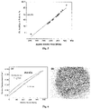
- FIG. 6 illustrates the energy density (19.6 J/cc) calculated from typical D-E loop of nanocomposites dielectric nanocomposite film (a); and red arrows illustrating how the nanocomposite films failed under high electric field (b).
- the present invention relates in general to high-energy density nanocomposite capacitors that include nanoceramic filler in a polymer material.
- the invention also relates to a nanocomposite having a high dielectric permittivity nanoengineered particle dispersed into a high breakdown strength polymer material to achieve high-energy density.
- the invention also related to nanocomposite films and a method for making such films.
- the nanocomposite films are formed in the following process: 1) create high dielectric permittivity ceramic fillers with core-shell structure and 2) modify the surface with functional groups. The resulted engineered nanoparticles are dispersed into the polymer material; the mixture is then solution cast into the thin nanocomposite films.
- the dielectric permittivity of the nanocomposite can be improved by incorporating high dielectric permittivity fillers into a polymer material.
- the invention is directed to a method to prepare doped nanoceramic fillers calcined at different temperatures to tune the dielectric properties of the nanocomposites.
- the novel fabrication method is generally comprised of the steps of 1) ball mill the powder, and 2) calcine the powder at different temperatures.
- high-energy density nanocomposite capacitor films can be based on the doped BaTiO 3 particles ((Ba 0.9575 Nd 0.0025 Ca 0.04 )[Ti 0.815 Mn 0.0025 Y 0.18 ] 0.997 O 3 ) that have a dielectric constant around 33,000 at room temperature which is about ten times higher than conventional BaTiO 3 particles.
- Doped barium titanate with the formula Ba 0.9575 Nd 0.0025 Ca 0.04 )[Ti 0.815 Mn 0.0025 Y 0.18 ] 0.997 O 3 was produced by ball milling BaCO 3 , Nd 2 O 3 , CaCO 3 , TiO 2 , MnCO 3 , and Y 2 O 3 for 24 hours.
- the mixed powder was then calcined at high temperature, such as 800° C. to 1300° C. (and all values therebetween). It is observed that different temperature calcining yields different crystal structure and particle size of doped materials.
- the nanocomposites with doped BaTiO 3 nanoparticles calcined at 900° C. have the highest dielectric permittivity.
- Other similar compositions will have a different optimum calcining temperature.
- Pb(Zr x Ti 1-x )O 3 Pb(Mg 1/3 Nb 2/3 )O 3 —PbTiO 3 (PMN-PT)
- BaTiO 3 and so on or any other high dielectric materials, for example, calcium copper titanate (CaCu 3 Ti 4 O 12 ).
- a high dielectric material has a dielectric constant (i.e., relative permittivity) at the frequency of 1 kHz at room temperature (e.g., 70° F.) of at least 100, typically at least 300, and more typically at least 500 (e.g., 100-100,000 and all values and ranges therebetween).
- a dielectric constant i.e., relative permittivity
- U energy density
- ⁇ the dielectric permittivity
- E the dielectric breakdown strength
- the invention is directed to improving the breakdown strength of the nanocomposite by creating gradient interfaces between the polymer material and the filler.
- the core-shell structure dielectric particle is designed.
- the shell materials typically have high dielectric permittivity, and the core materials are chosen from many that have exceptional high voltage breakdown (particularly in thin films) such as Al 2 O 3 , SiO 2 , mica, diamond and so on.
- This core-shell structure not only provides high dielectric permittivity, but also improves the breakdown strength of the shell.
- the shell structure can improve the high charge storage capability at the dielectric-dielectric interfaces.
- the thickness of the shell can range from 10 ⁇ to 500 nm, and in some cases from 5 ⁇ to 1000 nm (and all values therebetween).
- hierarchical particles are functionalized with different terminated groups to create the gradient interface between the polymer material and the filler.
- the gradient functional group not only improves the compatibility of the filler with the polymer material, but also improves the breakdowns strength of the nanocomposite.
- the terminated group can be any group to create the bond between the polymer material and filler, such as, but not limited to, amine group, hydroxyl group or others selected from phosphonate group, a silyl group, or a carboxylic group and others.
- the process for coating the one or more functional groups on the outer surface of the shell is non-limiting. Generally the thickness of the coating or layer of the one or more functional groups on the outer surface of the shell is about 1 ⁇ to 200 nm.
- the polymers can be selected from many dielectric films including polyvinylidene fluoride (PVDF), PVDF copolymers such as trifluoroethylene (P(VDF-TrFE)), hexafluoropropylene (P(VDF-HFP)) and chiorotrifluoroethylene (P(VDF-CTFE)) as well as terpolymers such as poly(vinylidene fluoride-trifluoroethylene-chlorofluoroethylene) (P(VDF-TrFE-CFE)), polytetrafluoroethylene (PTFE), polyimide (PI), TeflonTM, polyethylene naphthalate (PEN), polypropylene (PP), polycarbonate (PC), polystyrene (PS), polyphenylene sulfide (PPS), polyether ether ketone (PEEK
- PVDF polyvinylidene fluoride
- PVDF copolymers such as trifluoroethylene (P(VDF-T
- the nanofillers can be dispersed into the polymer solution; the nanocomposite films can then be solution cast into films. It is understood by one skilled in the art that these films can be made by extrusion, blown film techniques, calendaring and other film preparation techniques. The films can then be heat treated to reach high breakdown strength and high dielectric permittivity to reach high-energy density.
- the following example is directed to tape casting technology that provides a means for producing large quantities of thin film materials at a low cost.
- the system is easily scalable and ideal for processing material for capacitors, which require high-quantity, low-cost production.
- Doped barium titanate with the formula Ba 0.9575 Nd 0.0025 Ca 0.04 )[Ti 0.815 Mn 0.0025 Y 0.18 ] 0.997 O 3 was produced by ball milling BaCO 3 , Nd 2 O 3 , CaCO 3 , TiO 2 , MnCO 3 , and Y 2 O 3 for 24 hours. Different calcining temperatures will yield different final structures of the powder, thereby leading to a change in the dielectric properties of the materials.
- FIG. 1 illustrates the XRD patterns of the samples calcined at different temperatures (900° C., 1000° C., 1050° C., and 1200° C.). As illustrated in FIG.
- FIG. 2 is a graph illustrating the dielectric constant of the nanocomposites with the incorporation of 7.5 vol % BaTiO 3 ceramic fillers, which are calcined at different temperatures (950° C., 1000° C., 1150° C. and 1200° C.). It is showed that the dielectric constant of the nanocomposite is influenced by the filler nanoparticles, which are calcined at different temperatures. By adjusting the structure and particle of the ceramic fillers in the polymer material, the dielectric constant of the composites can be tuned.
- FIG. 3 schematically illustrates the hierarchical structure of ceramic fillers in the polymer material to create a high-energy density nanocomposite capacitor.
- high dielectric permittivity ceramic filler is designed as a core-shell structure.
- the core has a high dielectric permittivity, while the shell materials have high breakdown strength.
- particle cores occupy at least about 50% (e.g., 50-99% vol. % and all values and ranges therebetween) of the total of the volume in core-shell ceramic fillers; however, this is not required.
- Representative materials that can be used to form the core-shell structure can be any high dielectric permittivity materials (e.g., barium titanate, lead zirconium titanate, CCTO, etc.).
- the shell is a thin film with high breakdown strength materials to protect the high dielectric core structure.
- Representative materials can be any high-breakdown strength materials (e.g., Al 2 O 3 , SiO 2 , mica, diamond and others).
- the particle cores can have a variety of shapes (e.g., spherical, elongated, or irregular), and a variety of sizes.
- the particle cores have a relatively small size, usually less than about 100 ⁇ m (e.g., 0.05-500 ⁇ m and all values and ranges therebetween), and the thickness of the film is generally between about 0.1 nm to 1 ⁇ m (and all values and ranges therebewteen).
- FIG. 4 illustrates an example to create a gradient interface between the filler and polymer material, as well as a core-shell structure nanoparticle.
- the nano-engineered particle designed for the nano-laminated dielectric particle is illustrated in FIG. 4 a .
- high dielectric permittivity doped BaTiO 3 nanoparticles with around 100 nm were chosen as core materials.
- the coating materials have exceptional high voltage breakdown (particularly in thin films), as well as providing for high-charge storage at the dielectric-dielectric interfaces.
- the sol-gel process uses an ultrasonic horn to disperse BaTiO 3 in anhydrous ethanol, a solution of aluminum isopropoxide in anhydrous ethanol was then added to the BaTiO 3 dispersion, and was again blended ultrasonically to fully disperse and coat the particles. This step was followed by the addition of deionized water to the mixture.
- the aluminum isopropoxide which clings to the surface of the BaTiO 3 , undergoes a hydrolysis reaction and leaves aluminum oxide on the surface of the particles.
- the particles were then dried in air and calcined to densify the Al 2 O 3 surface coating.
- This method successfully coated the doped barium titanate with 10 nm Al 2 O 3 film observed in high-resolution transmission electron microscopy (HRTEM), as shown on the FIG. 4 b.
- HRTEM transmission electron microscopy
- nanocomposite films In order to prepare high-energy nanocomposite films, these nanoparticles can be dispersed in the dimethylformamide (DMF)/polyvinylidene fluoride (PVDF) solution by high-power horn solicitation.
- DMF dimethylformamide
- PVDF polyvinylidene fluoride
- the entire process developed by this invention encapsulation, surface function, high-power horn dispersion) stabilizes the particles in the solution for about one week, and sometimes more.
- Nanocomposite films were cast by using a solution casting method. The breakdown strength was measured by using an electrostatic pull-down method with Weibull distribution analysis as shown in FIG. 5 . Pull-down between the conductive substrate and a brass dome typically occurs at an electrical field of 10 MV/m and is maintained until breakdown occurs over the test area.
- the pull-down method was chosen over a point-contact method to avoid any mechanical force that might cause premature breakdown at the contact point.
- Breakdown testing was performed in silicon oil to avoid electric arcing and was performed using a high voltage supply by sweeping the applied voltage until sample failure, as evidenced by spurious current changes. Every sample was tested for at least 15 data points. Dielectric breakdown strength was then extracted from a fit using Weibull failure statistics across at least 15 tests per sample. Following the procedure developed in this invention, the dielectric strength of the nanocomposites can reach 442 MV/m. It should be noticed that the breakdown strength of the nanocomposites reported here is much higher than that of any composites reported in current literature.
- the polarization loop was measured with increasing electric field until breakdown occurred and the maximum energy could be recorded.
- the graph on the left side of FIG. 6 shows the typical D-E loops of the nanocomposite films. From the graph, it can be calculated that the nanocomposite film can achieve an energy density 19.6 J/cc.
- FIG. 6 b also demonstrates the self-healing ability of the metalized nanocomposite film.
- the current vaporizes the thin electrodes on the films in the immediate vicinity of the current flow (red arrow). This means that the local breakdown of the film nanocomposite will not influence the work status of the capacitor, and will help to greatly extend the life of the capacitor and the equipment in which it is installed.
Landscapes
- Engineering & Computer Science (AREA)
- Chemical & Material Sciences (AREA)
- Manufacturing & Machinery (AREA)
- Power Engineering (AREA)
- Mechanical Engineering (AREA)
- Chemical Kinetics & Catalysis (AREA)
- Microelectronics & Electronic Packaging (AREA)
- General Chemical & Material Sciences (AREA)
- Electrochemistry (AREA)
- Health & Medical Sciences (AREA)
- Organic Chemistry (AREA)
- Polymers & Plastics (AREA)
- Medicinal Chemistry (AREA)
- Composite Materials (AREA)
- Ceramic Engineering (AREA)
- Inorganic Chemistry (AREA)
- Spectroscopy & Molecular Physics (AREA)
- Physics & Mathematics (AREA)
- Materials Engineering (AREA)
- Nanotechnology (AREA)
- Inorganic Insulating Materials (AREA)
- Fixed Capacitors And Capacitor Manufacturing Machines (AREA)
Abstract
Description
Claims (53)
Priority Applications (1)
| Application Number | Priority Date | Filing Date | Title |
|---|---|---|---|
| US16/807,975 US11364693B2 (en) | 2015-10-19 | 2020-03-03 | Method for forming a high-energy density nanocomposite film |
Applications Claiming Priority (3)
| Application Number | Priority Date | Filing Date | Title |
|---|---|---|---|
| US201562243394P | 2015-10-19 | 2015-10-19 | |
| US15/294,936 US10647071B2 (en) | 2015-10-19 | 2016-10-17 | High-energy density nanocomposite capacitor |
| US16/807,975 US11364693B2 (en) | 2015-10-19 | 2020-03-03 | Method for forming a high-energy density nanocomposite film |
Related Parent Applications (1)
| Application Number | Title | Priority Date | Filing Date |
|---|---|---|---|
| US15/294,936 Continuation US10647071B2 (en) | 2015-10-19 | 2016-10-17 | High-energy density nanocomposite capacitor |
Publications (2)
| Publication Number | Publication Date |
|---|---|
| US20200376784A1 US20200376784A1 (en) | 2020-12-03 |
| US11364693B2 true US11364693B2 (en) | 2022-06-21 |
Family
ID=59311531
Family Applications (3)
| Application Number | Title | Priority Date | Filing Date |
|---|---|---|---|
| US15/294,936 Active 2037-07-12 US10647071B2 (en) | 2015-10-19 | 2016-10-17 | High-energy density nanocomposite capacitor |
| US16/807,975 Expired - Fee Related US11364693B2 (en) | 2015-10-19 | 2020-03-03 | Method for forming a high-energy density nanocomposite film |
| US16/807,996 Active 2038-04-02 US11673353B2 (en) | 2015-10-19 | 2020-03-03 | High-energy density nanocomposite capacitor |
Family Applications Before (1)
| Application Number | Title | Priority Date | Filing Date |
|---|---|---|---|
| US15/294,936 Active 2037-07-12 US10647071B2 (en) | 2015-10-19 | 2016-10-17 | High-energy density nanocomposite capacitor |
Family Applications After (1)
| Application Number | Title | Priority Date | Filing Date |
|---|---|---|---|
| US16/807,996 Active 2038-04-02 US11673353B2 (en) | 2015-10-19 | 2020-03-03 | High-energy density nanocomposite capacitor |
Country Status (2)
| Country | Link |
|---|---|
| US (3) | US10647071B2 (en) |
| WO (1) | WO2017123300A1 (en) |
Families Citing this family (13)
| Publication number | Priority date | Publication date | Assignee | Title |
|---|---|---|---|---|
| US10647071B2 (en) * | 2015-10-19 | 2020-05-12 | Powdermet Inc. | High-energy density nanocomposite capacitor |
| CN113646911B (en) * | 2019-04-02 | 2025-11-04 | 沙特基础全球技术有限公司 | Lead-free piezoelectric composite materials and their preparation methods |
| CN111303576B (en) * | 2020-02-29 | 2022-03-29 | 杭州电子科技大学 | Application of composite film material as energy storage material and preparation method thereof |
| CN111371435B (en) * | 2020-03-18 | 2023-06-13 | 中国工程物理研究院流体物理研究所 | Application of Explosive Power Sources in Multilayer Ferroelectric Thin Film Stacks |
| US11130296B1 (en) | 2020-03-24 | 2021-09-28 | Prince Mohammad Bin Fahd University | Method of forming electrically and thermally conductive polyolefin-perovskite nanomaterial composites having increased dielectric permittivity and breakdown-induced electrical and thermal conduction pathways |
| CN111548515B (en) * | 2020-04-15 | 2023-05-09 | 哈尔滨理工大学 | A post-treatment process of non-oxide ceramic/polyvinylidene fluoride composite film |
| EP4567054B1 (en) | 2020-06-30 | 2025-12-17 | Novocure GmbH | Flexible transducer arrays with a polymer insulating layer for applying tumor treating fields (ttfields) |
| CN112062979B (en) * | 2020-09-07 | 2022-04-19 | 清华大学 | Organic-inorganic core-shell structure self-lubricating composite material and preparation method thereof |
| CN113385053A (en) * | 2021-05-07 | 2021-09-14 | 苏州科技大学 | PTFE emulsion blending modified PVDF membrane and preparation method thereof |
| CN113150554B (en) * | 2021-05-25 | 2023-02-14 | 南京邮电大学 | PDMS-based flexible energy storage composite membrane and preparation method thereof |
| CN113964294B (en) * | 2021-10-28 | 2024-04-12 | 西安交通大学 | Lithium ion battery negative electrode and preparation method and application thereof |
| CN114148003B (en) * | 2021-11-22 | 2024-02-06 | 成都迈科高分子材料股份有限公司 | Method for preparing multilayer capacitance film modified by plasma |
| US20250069810A1 (en) | 2022-01-04 | 2025-02-27 | University Of Southern Denmark | Composite Dielectric Material, Capacitor and Methods for producing said Composite Dielectric Material and said Capacitor |
Citations (12)
| Publication number | Priority date | Publication date | Assignee | Title |
|---|---|---|---|---|
| US4086649A (en) | 1974-12-26 | 1978-04-25 | Union Carbide Corporation | Ceramic capacitor made from firing small barium titanate particles |
| US5700548A (en) | 1993-10-06 | 1997-12-23 | U.S. Philips Corporation | Multilayer film, multicolour screen-printing process for the manufacture of said multilayer film and the use of same |
| US20040071944A1 (en) | 2001-04-12 | 2004-04-15 | Weir Richard Dean | Electrical-energy-storage unit (EESU) utilizing ceramic and integrated-circuit technologies for replacement of electrochemical batteries |
| US20060167139A1 (en) | 2005-01-27 | 2006-07-27 | Nelson John K | Nanostructured dielectric composite materials |
| US20100160994A1 (en) | 2007-01-04 | 2010-06-24 | Board Of Regents, The University Of Texas System | Cardiovascular power source for automatic implantable cardioverter defibrillators |
| US20100209779A1 (en) | 2009-02-02 | 2010-08-19 | Recapping, Inc. | High energy density electrical energy storage devices |
| US20110212382A1 (en) | 2009-10-13 | 2011-09-01 | The Penn State Research Foundation | High energy density ionic dielectric materials and devices |
| US20120295448A1 (en) | 2011-04-13 | 2012-11-22 | Empire Technology Development Llc | Dielectric nanocomposites and methods of making the same |
| WO2014182245A1 (en) | 2013-05-07 | 2014-11-13 | Nanyang Technological University | Ceramic-polymer nanocomposites |
| WO2015006030A1 (en) | 2013-07-06 | 2015-01-15 | Frank David L | Dense energy ultra-capacitor preform, thin film, module and fabrication methods therefor |
| CN104893187A (en) | 2015-04-09 | 2015-09-09 | 同济大学 | High energy storage density and efficiency polymer composite film and preparation method thereof |
| US10647071B2 (en) * | 2015-10-19 | 2020-05-12 | Powdermet Inc. | High-energy density nanocomposite capacitor |
Family Cites Families (1)
| Publication number | Priority date | Publication date | Assignee | Title |
|---|---|---|---|---|
| CN105295263B (en) * | 2015-11-11 | 2017-11-07 | 同济大学 | A kind of polymer matrix composite and preparation method thereof |
-
2016
- 2016-10-17 US US15/294,936 patent/US10647071B2/en active Active
- 2016-10-17 WO PCT/US2016/057276 patent/WO2017123300A1/en not_active Ceased
-
2020
- 2020-03-03 US US16/807,975 patent/US11364693B2/en not_active Expired - Fee Related
- 2020-03-03 US US16/807,996 patent/US11673353B2/en active Active
Patent Citations (16)
| Publication number | Priority date | Publication date | Assignee | Title |
|---|---|---|---|---|
| US4086649A (en) | 1974-12-26 | 1978-04-25 | Union Carbide Corporation | Ceramic capacitor made from firing small barium titanate particles |
| US5700548A (en) | 1993-10-06 | 1997-12-23 | U.S. Philips Corporation | Multilayer film, multicolour screen-printing process for the manufacture of said multilayer film and the use of same |
| US20040071944A1 (en) | 2001-04-12 | 2004-04-15 | Weir Richard Dean | Electrical-energy-storage unit (EESU) utilizing ceramic and integrated-circuit technologies for replacement of electrochemical batteries |
| US7033406B2 (en) * | 2001-04-12 | 2006-04-25 | Eestor, Inc. | Electrical-energy-storage unit (EESU) utilizing ceramic and integrated-circuit technologies for replacement of electrochemical batteries |
| US20060167139A1 (en) | 2005-01-27 | 2006-07-27 | Nelson John K | Nanostructured dielectric composite materials |
| US7579397B2 (en) * | 2005-01-27 | 2009-08-25 | Rensselaer Polytechnic Institute | Nanostructured dielectric composite materials |
| US20100160994A1 (en) | 2007-01-04 | 2010-06-24 | Board Of Regents, The University Of Texas System | Cardiovascular power source for automatic implantable cardioverter defibrillators |
| US20100209779A1 (en) | 2009-02-02 | 2010-08-19 | Recapping, Inc. | High energy density electrical energy storage devices |
| US20110212382A1 (en) | 2009-10-13 | 2011-09-01 | The Penn State Research Foundation | High energy density ionic dielectric materials and devices |
| US8906818B2 (en) * | 2009-10-13 | 2014-12-09 | Recapping, Inc. | High energy density ionic dielectric materials and devices |
| US20120295448A1 (en) | 2011-04-13 | 2012-11-22 | Empire Technology Development Llc | Dielectric nanocomposites and methods of making the same |
| US8889472B2 (en) * | 2011-04-13 | 2014-11-18 | Empire Technology Development Llc | Dielectric nanocomposites and methods of making the same |
| WO2014182245A1 (en) | 2013-05-07 | 2014-11-13 | Nanyang Technological University | Ceramic-polymer nanocomposites |
| WO2015006030A1 (en) | 2013-07-06 | 2015-01-15 | Frank David L | Dense energy ultra-capacitor preform, thin film, module and fabrication methods therefor |
| CN104893187A (en) | 2015-04-09 | 2015-09-09 | 同济大学 | High energy storage density and efficiency polymer composite film and preparation method thereof |
| US10647071B2 (en) * | 2015-10-19 | 2020-05-12 | Powdermet Inc. | High-energy density nanocomposite capacitor |
Non-Patent Citations (3)
| Title |
|---|
| Li et al., "Dielectric properties of binary polyvinylidene fluoride/barium titanate nanocomposites and their nanographic doped hybrids", Polymer Letter, vol. 5, issue 6; pp. 526-534 (2011). |
| Liu et al., "Improving the dielectric constant and energy density of poly(vinylidene fluoride) composites induced by surface-modified SrTi03 nanofibers by polyvinylpyrrolidone", Journal of Materials Chemistry; vol. 3; issue 4; pp. 1511-1518 (2015). |
| U.S. Search Authority, International Search Report and Written Opinion issued to related PCT/US2016/057276 (dated Jun. 2017). |
Also Published As
| Publication number | Publication date |
|---|---|
| US10647071B2 (en) | 2020-05-12 |
| US11673353B2 (en) | 2023-06-13 |
| US20200376784A1 (en) | 2020-12-03 |
| US20170301466A1 (en) | 2017-10-19 |
| US20200376785A1 (en) | 2020-12-03 |
| WO2017123300A1 (en) | 2017-07-20 |
Similar Documents
| Publication | Publication Date | Title |
|---|---|---|
| US11673353B2 (en) | High-energy density nanocomposite capacitor | |
| Pan et al. | Dielectric films for high performance capacitive energy storage: multiscale engineering | |
| Wang et al. | Lead-free (Ba, Sr) TiO3–BiFeO3 based multilayer ceramic capacitors with high energy density | |
| Peddigari et al. | Linear and nonlinear dielectric ceramics for high-power energy storage capacitor applications | |
| Chi et al. | Significantly enhanced energy storage density for poly (vinylidene fluoride) composites by induced PDA-coated 0.5 Ba (Zr0. 2Ti0. 8) O3–0.5 (Ba0. 7Ca0. 3) TiO3 nanofibers | |
| Yang et al. | Relaxor ferroelectric (Na0. 5Bi0. 5) 0.4 Sr0. 6TiO3-based ceramics for energy storage application | |
| JP5824197B2 (en) | Film capacitor | |
| Thomas et al. | Dielectric properties of poly (vinylidene fluoride)/CaCu3Ti4O12 composites | |
| JP5197945B2 (en) | Antiferroelectric polymer composite material, method for producing the same, and article comprising the same | |
| Wei et al. | Relaxor behavior of BaTiO3-BiYO3 perovskite materials for high energy density capacitors | |
| US12163005B2 (en) | Multilayer and flexible capacitors with metal-ion doped TIO2 colossal permittivity material/polymer composites | |
| JP2010278430A (en) | Composite structures for high energy density capacitors and other devices | |
| Jain et al. | Grain size engineered Ba0. 9Sr0. 1Ti0. 9Hf0. 1O3‐Na0. 5Bi0. 5TiO3 relaxor ceramics with improved energy storage performance | |
| JP2018117126A (en) | Dielectric composite, multilayer capacitor and electronic device including the same | |
| Bilal et al. | A novel relaxor (Bi, Na, Ba)(Ti, Zr) O3 lead‐free ceramic with high energy storage performance | |
| JP2010013642A (en) | High temperature polymer composite and method of producing the same | |
| Guo et al. | High energy density in PVDF nanocomposites using an optimized nanowire array | |
| Kumar et al. | Increased energy-storage density and superior electric field and thermally stable energy efficiency of aerosol-deposited relaxor (Pb0. 89La0. 11)(Zr0. 70Ti0. 30) O3 films | |
| Xia et al. | Energy storage BaZr0. 2Ti0. 8O3 bilayer relaxor ferroelectric ceramic thick films with high discharging efficiency and fatigue resistance | |
| Mahmood et al. | High-k polymer nanocomposites for energy storage applications | |
| JP6402652B2 (en) | Dielectric composition and electronic component | |
| Lakouader et al. | BCZT/LSMO/BCZT multilayer films for high temperature energy storage capacitors | |
| Patra et al. | Ceramic Multilayers and Films for High‐Performance Supercapacitors | |
| Chao | Ceramic dielectrics for high energy density capacitor application | |
| Nath et al. | 15 Hybrid High-K Dielectrics for |
Legal Events
| Date | Code | Title | Description |
|---|---|---|---|
| FEPP | Fee payment procedure |
Free format text: ENTITY STATUS SET TO UNDISCOUNTED (ORIGINAL EVENT CODE: BIG.); ENTITY STATUS OF PATENT OWNER: SMALL ENTITY |
|
| FEPP | Fee payment procedure |
Free format text: ENTITY STATUS SET TO SMALL (ORIGINAL EVENT CODE: SMAL); ENTITY STATUS OF PATENT OWNER: SMALL ENTITY |
|
| AS | Assignment |
Owner name: POWDERMET INC., OHIO Free format text: ASSIGNMENT OF ASSIGNORS INTEREST;ASSIGNORS:SHERMAN, ANDREW;TANG, HAIXONG;DOUD, BRIAN;REEL/FRAME:052746/0186 Effective date: 20151021 |
|
| STPP | Information on status: patent application and granting procedure in general |
Free format text: DOCKETED NEW CASE - READY FOR EXAMINATION |
|
| STPP | Information on status: patent application and granting procedure in general |
Free format text: NON FINAL ACTION MAILED |
|
| STPP | Information on status: patent application and granting procedure in general |
Free format text: RESPONSE TO NON-FINAL OFFICE ACTION ENTERED AND FORWARDED TO EXAMINER |
|
| STPP | Information on status: patent application and granting procedure in general |
Free format text: NOTICE OF ALLOWANCE MAILED -- APPLICATION RECEIVED IN OFFICE OF PUBLICATIONS |
|
| STPP | Information on status: patent application and granting procedure in general |
Free format text: PUBLICATIONS -- ISSUE FEE PAYMENT VERIFIED |
|
| STCF | Information on status: patent grant |
Free format text: PATENTED CASE |
|
| FEPP | Fee payment procedure |
Free format text: MAINTENANCE FEE REMINDER MAILED (ORIGINAL EVENT CODE: REM.); ENTITY STATUS OF PATENT OWNER: SMALL ENTITY |
|
| LAPS | Lapse for failure to pay maintenance fees |
Free format text: PATENT EXPIRED FOR FAILURE TO PAY MAINTENANCE FEES (ORIGINAL EVENT CODE: EXP.); ENTITY STATUS OF PATENT OWNER: SMALL ENTITY |
|
| STCH | Information on status: patent discontinuation |
Free format text: PATENT EXPIRED DUE TO NONPAYMENT OF MAINTENANCE FEES UNDER 37 CFR 1.362 |