US11364083B2 - Joint locking mechanism of passive robotic arm - Google Patents

Joint locking mechanism of passive robotic arm Download PDF

Info

Publication number
US11364083B2
US11364083B2 US16/320,043 US201816320043A US11364083B2 US 11364083 B2 US11364083 B2 US 11364083B2 US 201816320043 A US201816320043 A US 201816320043A US 11364083 B2 US11364083 B2 US 11364083B2
Authority
US
United States
Prior art keywords
output shaft
threaded
joint output
shaft
joint
Prior art date
Legal status (The legal status is an assumption and is not a legal conclusion. Google has not performed a legal analysis and makes no representation as to the accuracy of the status listed.)
Active, expires
Application number
US16/320,043
Other versions
US20210369358A1 (en
Inventor
Shaolong KUANG
Jinzhong Li
Li Zhang
Andi LIN
Liansen SHA
Shumei YU
Fengfeng ZHANG
Lining Sun
Current Assignee (The listed assignees may be inaccurate. Google has not performed a legal analysis and makes no representation or warranty as to the accuracy of the list.)
Suzhou University
Original Assignee
Suzhou University
Priority date (The priority date is an assumption and is not a legal conclusion. Google has not performed a legal analysis and makes no representation as to the accuracy of the date listed.)
Filing date
Publication date
Application filed by Suzhou University filed Critical Suzhou University
Assigned to SOOCHOW UNIVERSITY reassignment SOOCHOW UNIVERSITY ASSIGNMENT OF ASSIGNORS INTEREST (SEE DOCUMENT FOR DETAILS). Assignors: SHA, Liansen, KUANG, Shaolong, LI, JINZHONG, LIN, Andi, SUN, LINING, YU, Shumei, ZHANG, FENGFENG, ZHANG, LI
Publication of US20210369358A1 publication Critical patent/US20210369358A1/en
Application granted granted Critical
Publication of US11364083B2 publication Critical patent/US11364083B2/en
Active legal-status Critical Current
Adjusted expiration legal-status Critical

Links

Images

Classifications

    • BPERFORMING OPERATIONS; TRANSPORTING
    • B25HAND TOOLS; PORTABLE POWER-DRIVEN TOOLS; MANIPULATORS
    • B25JMANIPULATORS; CHAMBERS PROVIDED WITH MANIPULATION DEVICES
    • B25J19/00Accessories fitted to manipulators, e.g. for monitoring, for viewing; Safety devices combined with or specially adapted for use in connection with manipulators
    • B25J19/0004Braking devices
    • BPERFORMING OPERATIONS; TRANSPORTING
    • B25HAND TOOLS; PORTABLE POWER-DRIVEN TOOLS; MANIPULATORS
    • B25JMANIPULATORS; CHAMBERS PROVIDED WITH MANIPULATION DEVICES
    • B25J17/00Joints
    • AHUMAN NECESSITIES
    • A61MEDICAL OR VETERINARY SCIENCE; HYGIENE
    • A61BDIAGNOSIS; SURGERY; IDENTIFICATION
    • A61B34/00Computer-aided surgery; Manipulators or robots specially adapted for use in surgery
    • A61B34/30Surgical robots
    • AHUMAN NECESSITIES
    • A61MEDICAL OR VETERINARY SCIENCE; HYGIENE
    • A61BDIAGNOSIS; SURGERY; IDENTIFICATION
    • A61B34/00Computer-aided surgery; Manipulators or robots specially adapted for use in surgery
    • A61B34/70Manipulators specially adapted for use in surgery
    • AHUMAN NECESSITIES
    • A61MEDICAL OR VETERINARY SCIENCE; HYGIENE
    • A61BDIAGNOSIS; SURGERY; IDENTIFICATION
    • A61B90/00Instruments, implements or accessories specially adapted for surgery or diagnosis and not covered by any of the groups A61B1/00 - A61B50/00, e.g. for luxation treatment or for protecting wound edges
    • A61B90/50Supports for surgical instruments, e.g. articulated arms
    • BPERFORMING OPERATIONS; TRANSPORTING
    • B25HAND TOOLS; PORTABLE POWER-DRIVEN TOOLS; MANIPULATORS
    • B25JMANIPULATORS; CHAMBERS PROVIDED WITH MANIPULATION DEVICES
    • B25J9/00Programme-controlled manipulators
    • B25J9/10Programme-controlled manipulators characterised by positioning means for manipulator elements
    • B25J9/109Programme-controlled manipulators characterised by positioning means for manipulator elements comprising mechanical programming means, e.g. cams
    • FMECHANICAL ENGINEERING; LIGHTING; HEATING; WEAPONS; BLASTING
    • F16ENGINEERING ELEMENTS AND UNITS; GENERAL MEASURES FOR PRODUCING AND MAINTAINING EFFECTIVE FUNCTIONING OF MACHINES OR INSTALLATIONS; THERMAL INSULATION IN GENERAL
    • F16DCOUPLINGS FOR TRANSMITTING ROTATION; CLUTCHES; BRAKES
    • F16D55/00Brakes with substantially-radial braking surfaces pressed together in axial direction, e.g. disc brakes
    • F16D55/02Brakes with substantially-radial braking surfaces pressed together in axial direction, e.g. disc brakes with axially-movable discs or pads pressed against axially-located rotating members
    • FMECHANICAL ENGINEERING; LIGHTING; HEATING; WEAPONS; BLASTING
    • F16ENGINEERING ELEMENTS AND UNITS; GENERAL MEASURES FOR PRODUCING AND MAINTAINING EFFECTIVE FUNCTIONING OF MACHINES OR INSTALLATIONS; THERMAL INSULATION IN GENERAL
    • F16DCOUPLINGS FOR TRANSMITTING ROTATION; CLUTCHES; BRAKES
    • F16D59/00Self-acting brakes, e.g. coming into operation at a predetermined speed
    • F16D59/02Self-acting brakes, e.g. coming into operation at a predetermined speed spring-loaded and adapted to be released by mechanical, fluid, or electromagnetic means
    • FMECHANICAL ENGINEERING; LIGHTING; HEATING; WEAPONS; BLASTING
    • F16ENGINEERING ELEMENTS AND UNITS; GENERAL MEASURES FOR PRODUCING AND MAINTAINING EFFECTIVE FUNCTIONING OF MACHINES OR INSTALLATIONS; THERMAL INSULATION IN GENERAL
    • F16DCOUPLINGS FOR TRANSMITTING ROTATION; CLUTCHES; BRAKES
    • F16D65/00Parts or details
    • F16D65/14Actuating mechanisms for brakes; Means for initiating operation at a predetermined position
    • F16D65/16Actuating mechanisms for brakes; Means for initiating operation at a predetermined position arranged in or on the brake
    • F16D65/18Actuating mechanisms for brakes; Means for initiating operation at a predetermined position arranged in or on the brake adapted for drawing members together, e.g. for disc brakes
    • F16D65/186Actuating mechanisms for brakes; Means for initiating operation at a predetermined position arranged in or on the brake adapted for drawing members together, e.g. for disc brakes with full-face force-applying member, e.g. annular
    • AHUMAN NECESSITIES
    • A61MEDICAL OR VETERINARY SCIENCE; HYGIENE
    • A61BDIAGNOSIS; SURGERY; IDENTIFICATION
    • A61B90/00Instruments, implements or accessories specially adapted for surgery or diagnosis and not covered by any of the groups A61B1/00 - A61B50/00, e.g. for luxation treatment or for protecting wound edges
    • A61B90/50Supports for surgical instruments, e.g. articulated arms
    • A61B2090/508Supports for surgical instruments, e.g. articulated arms with releasable brake mechanisms
    • FMECHANICAL ENGINEERING; LIGHTING; HEATING; WEAPONS; BLASTING
    • F16ENGINEERING ELEMENTS AND UNITS; GENERAL MEASURES FOR PRODUCING AND MAINTAINING EFFECTIVE FUNCTIONING OF MACHINES OR INSTALLATIONS; THERMAL INSULATION IN GENERAL
    • F16DCOUPLINGS FOR TRANSMITTING ROTATION; CLUTCHES; BRAKES
    • F16D2121/00Type of actuator operation force
    • F16D2121/005Type of actuator operation force unspecified force for releasing a normally applied brake
    • FMECHANICAL ENGINEERING; LIGHTING; HEATING; WEAPONS; BLASTING
    • F16ENGINEERING ELEMENTS AND UNITS; GENERAL MEASURES FOR PRODUCING AND MAINTAINING EFFECTIVE FUNCTIONING OF MACHINES OR INSTALLATIONS; THERMAL INSULATION IN GENERAL
    • F16DCOUPLINGS FOR TRANSMITTING ROTATION; CLUTCHES; BRAKES
    • F16D2121/00Type of actuator operation force
    • F16D2121/14Mechanical
    • F16D2121/16Mechanical for releasing a normally applied brake
    • FMECHANICAL ENGINEERING; LIGHTING; HEATING; WEAPONS; BLASTING
    • F16ENGINEERING ELEMENTS AND UNITS; GENERAL MEASURES FOR PRODUCING AND MAINTAINING EFFECTIVE FUNCTIONING OF MACHINES OR INSTALLATIONS; THERMAL INSULATION IN GENERAL
    • F16DCOUPLINGS FOR TRANSMITTING ROTATION; CLUTCHES; BRAKES
    • F16D2125/00Components of actuators
    • F16D2125/18Mechanical mechanisms
    • F16D2125/20Mechanical mechanisms converting rotation to linear movement or vice versa
    • F16D2125/34Mechanical mechanisms converting rotation to linear movement or vice versa acting in the direction of the axis of rotation
    • F16D2125/40Screw-and-nut

Definitions

  • the present application relates to a joint locking mechanism of a passive robotic arm.
  • Joint locking mechanisms in the prior art are mainly hydraulic, pneumatic, electromagnetic, or mechanical. Because of bringing contamination to the operating room and the large size, hydraulic and pneumatic joint locking mechanisms' application is limited. Although electromagnetic locking mechanisms following the same principle of the power-off braking have simple structures, they can only provide limited locking force with micro size. Ideally, a joint locking mechanism based on purely mechanical locking is desired for its simple structure and operability, which will ease the psychological pressure on the surgeon. Such a joint locking mechanism does not require any special manipulating environment and will not bring contamination to the operating room.
  • the present application provides a joint locking mechanism driven purely mechanically based on the principle of frictional locking.
  • a joint locking mechanism of a passive robotic arm comprising: an output assembly, including a joint output shaft, and a friction disk fixed to the joint output shaft; a braking assembly, including a threaded shaft arranged coaxially with the joint output shaft, a threaded sleeve threaded to the threaded shaft, a rotary disk connected fixedly to the threaded shaft, an end cap rotatable relative to the rotary disk, and a scroll spring generating a rotational force on the threaded shaft.
  • the scroll spring has one end connected fixedly to the end cap and the other end connected to the rotary disk or the threaded shaft.
  • the threaded sleeve is abutted tightly against the friction disk.
  • the scroll spring causes a tendency for the threaded shaft to rotate, thereby causing a tendency for the threaded sleeve fitted over the threaded shaft to move towards the joint output shaft, so that the threaded sleeve is pressed tightly on the friction disk, whereupon the friction disk under pressure causes the joint output shaft to be braked.
  • the mechanism further comprises a housing, wherein the threaded sleeve is positioned within the housing, the housing is provided with a guide slot extending along the joint output shaft, and at least one positioning hole is provided in the threaded sleeve.
  • the mechanism further comprises a pin extending through the guide slot with an end portion thereof inserted in the positioning hole.
  • the joint output shaft is provided with a key mounting slot.
  • a key is mounted within the key mounting slot.
  • the key is protruded relative to the surface of the joint output shaft.
  • a spline is further sleeved over the joint output shaft.
  • the friction disk is fixed to the joint output shaft via the spline.
  • the key is used to prevent the spline from sliding relative to the joint output shaft.
  • the spline can simplify installation and prevent the friction disk from sliding relative to the joint output shaft.
  • the rotary disk is sleeved over an end portion of the threaded shaft away from the joint output shaft.
  • the threaded sleeve is sleeved over the threaded shaft proximate to the joint output shaft.
  • the end cap is sleeved on the threaded shaft and positioned between the rotary disk and the threaded sleeve.
  • the scroll spring is positioned in the end cap and sleeved over the threaded shaft.
  • the end cap is mounted fixedly on an end portion of the housing.
  • the end portion of the threaded shaft away from the joint output shaft is rotatably mounted on the end cap.
  • the joint output shaft is rotatably mounted within the housing.
  • the joint locking mechanism of a passive robotic arm is used for medical surgeries to provide joint locking.
  • a rotational force is applied to the threaded shaft by the scroll spring, causing the threaded shaft to rotate in an opposite direction and drive the threaded sleeve to move towards the friction disk along the joint output shaft and be pressed tightly against the friction disk again, so that the joint output shaft is braked.
  • the threaded sleeve can only move back and forth along the length of a guide slot and along the joint output shaft.
  • FIG. 1 is an exploded structural view of a locking mechanism according to the present application
  • FIG. 2 is a structural view of a locking mechanism according to the present application.
  • FIG. 3 is a sectional structural view of a locking mechanism according to the present application.
  • the present application provides a joint locking mechanism of a passive robotic arm, comprising: an output assembly, including a joint output shaft 2 , and a friction disk 5 fixed to the joint output shaft 2 ; a braking assembly, including a threaded shaft 7 arranged coaxially with the joint output shaft 2 , a threaded sleeve 4 threaded to the threaded shaft 7 , a rotary disk 8 connected fixedly to the threaded shaft 7 , an end cap 9 rotatable relative to the rotary disk 8 , and a scroll spring 10 generating a rotational force on the threaded shaft 7 .
  • the scroll spring 10 has one end connected fixedly to the end cap 9 and the other end connected to the rotary disk 8 or the threaded shaft 7 .
  • the threaded sleeve 4 is abutted tightly against the friction disk 5 .
  • the mechanism further comprises a housing 1 .
  • the threaded sleeve 4 is positioned within the housing 1 .
  • the housing 1 is provided with a guide slot 11 extending along the joint output shaft 2 .
  • At least one positioning hole 41 is provided in the threaded sleeve 4 .
  • the mechanism further comprises a pin extending through the guide slot 11 with an end portion thereof inserted in the positioning hole 41 .
  • the joint output shaft 2 is provided with a key mounting slot 21 .
  • a key 3 is mounted within the key mounting slot 21 .
  • the key 3 is protruded relative to the surface of the joint output shaft 2 .
  • a spline 6 is further sleeved over the joint output shaft 2 .
  • the friction disk 5 is fixed to the joint output shaft 2 via the spline 6 .
  • the key 3 is used to prevent the spline 6 from sliding relative to the joint output shaft 2 .
  • the spline 6 can simplify installation and prevent the friction disk 5 from sliding relative to the joint output shaft 2 .
  • the rotary disk 8 is sleeved over an end portion of the threaded shaft 7 away from the joint output shaft 2 .
  • the threaded sleeve 4 is sleeved over an end portion of the threaded shaft 7 proximate to the joint output shaft 2 .
  • the end cap 9 is sleeved on the threaded shaft 7 and positioned between the rotary disk 8 and the threaded sleeve 4 .
  • the scroll spring 10 is positioned in the end cap 9 and sleeved over the threaded shaft 7 .
  • the end cap 9 is mounted fixedly on an end portion of the housing 1 .
  • the end portion of the threaded shaft 7 away from the joint output shaft 2 is rotatably mounted on the end cap 9 .
  • the joint output shaft 2 is rotatably mounted within the housing 1 .
  • the joint locking mechanism of a passive robotic arm is operated as follows: when there is no external force applied, the scroll spring 10 causes a tendency for the threaded shaft 7 to rotate, thereby causing a tendency for the threaded sleeve 4 fitted over the threaded shaft 7 to move towards the joint output shaft 2 , so that the threaded sleeve 4 is pressed tightly against the friction disk 5 , whereupon the friction disk 5 under pressure causes the joint output shaft 2 to be braked.
  • the rotary disk 8 drives the threaded shaft 7 to rotate in a direction opposite to the tendency of rotation in a stationary state and drives the threaded sleeve 4 to move away from the friction disk 5 along the joint output shaft 2 , so as to release the friction disk 5 and allow the joint output shaft 2 to start rotating.
  • a rotational force is applied to the threaded shaft 7 by the scroll spring 10 , causing the threaded shaft 7 to rotate in an opposite direction and drive the threaded sleeve 4 to move towards the friction disk 5 along the joint output shaft 2 and be pressed tightly against the friction disk 5 again, so that the joint output shaft 2 is braked.
  • the threaded sleeve 4 can only move back and forth along the length of the guide slot and along the joint output shaft 2 .
  • the joint locking mechanism of a passive robotic arm is used for medical surgeries to provide joint locking.
  • a rotational force is applied to the threaded shaft 7 by the scroll spring 10 , causing the threaded shaft 7 to rotate in an opposite direction and drive the threaded sleeve 4 to move towards the friction disk 5 along the joint output shaft 2 and be pressed tightly against the friction disk 5 again, so that the joint output shaft 2 is braked.
  • the threaded sleeve 4 is limited to only move back and forth along the length of the guide slot and along the joint output shaft 2 .

Landscapes

  • Engineering & Computer Science (AREA)
  • Health & Medical Sciences (AREA)
  • Surgery (AREA)
  • Life Sciences & Earth Sciences (AREA)
  • Robotics (AREA)
  • Mechanical Engineering (AREA)
  • General Engineering & Computer Science (AREA)
  • Molecular Biology (AREA)
  • Veterinary Medicine (AREA)
  • Medical Informatics (AREA)
  • Biomedical Technology (AREA)
  • Animal Behavior & Ethology (AREA)
  • General Health & Medical Sciences (AREA)
  • Public Health (AREA)
  • Heart & Thoracic Surgery (AREA)
  • Nuclear Medicine, Radiotherapy & Molecular Imaging (AREA)
  • Pathology (AREA)
  • Oral & Maxillofacial Surgery (AREA)
  • Physics & Mathematics (AREA)
  • Electromagnetism (AREA)
  • Manipulator (AREA)
  • Braking Arrangements (AREA)

Abstract

A joint locking mechanism of a passive robotic arm includes: an output assembly, including a joint output shaft, and a friction disk fixed to the joint output shaft; a braking assembly, including a threaded shaft arranged coaxially with the joint output shaft, a threaded sleeve threaded to the threaded shaft, a rotary disk connected fixedly to the threaded shaft, an end cap rotatable relative to the rotary disk, and a scroll spring generating a rotational force on the threaded shaft. The scroll spring has one end connected fixedly to the end cap and the other end connected to the rotary disk or the threaded shaft. The threaded sleeve is abutted tightly against the friction disk.

Description

This application is the National Phase Application of PCT/CN2018/072932, filed on Jan. 17, 2018, which claims priority to Chinese Patent Application No.: 201711483123.5, filed on Dec. 29, 2017, each of which is incorporated by reference for all purposes as if fully set forth herein.
FIELD OF THE INVENTION
The present application relates to a joint locking mechanism of a passive robotic arm.
BACKGROUND OF THE INVENTION
Recently, with the development in medical robots, medical robots have become an important branch in the field of robots and also an important research subject in the field of biomedical engineering. It has been shown that one of the major challenges for medical robots to be applied in clinics according to research and clinical practice about medical robots over the past 30 years is the safety. And in particular, the robot powered electrically, hydraulically or pneumatically is an open loop device, which interacts directly with the surgeon and patient and thus brings a lot of psychological pressure on clinicians. Therefore, it has become a focus in research and development on medical robots to develop a passive robotic arm without being driven by power for assisting in navigation surgeries or installation of a powered micro surgical robot.
An important subject in the study of passive robotic arms is to develop a joint locking mechanism. Joint locking mechanisms in the prior art are mainly hydraulic, pneumatic, electromagnetic, or mechanical. Because of bringing contamination to the operating room and the large size, hydraulic and pneumatic joint locking mechanisms' application is limited. Although electromagnetic locking mechanisms following the same principle of the power-off braking have simple structures, they can only provide limited locking force with micro size. Ideally, a joint locking mechanism based on purely mechanical locking is desired for its simple structure and operability, which will ease the psychological pressure on the surgeon. Such a joint locking mechanism does not require any special manipulating environment and will not bring contamination to the operating room.
SUMMARY OF THE INVENTION
To fulfill the need of such passive robotic arm in clinics, the present application provides a joint locking mechanism driven purely mechanically based on the principle of frictional locking.
In order to solve the technical problem mentioned above, the present application provides a joint locking mechanism of a passive robotic arm, comprising: an output assembly, including a joint output shaft, and a friction disk fixed to the joint output shaft; a braking assembly, including a threaded shaft arranged coaxially with the joint output shaft, a threaded sleeve threaded to the threaded shaft, a rotary disk connected fixedly to the threaded shaft, an end cap rotatable relative to the rotary disk, and a scroll spring generating a rotational force on the threaded shaft. The scroll spring has one end connected fixedly to the end cap and the other end connected to the rotary disk or the threaded shaft. The threaded sleeve is abutted tightly against the friction disk. When there is no external force applied, the scroll spring causes a tendency for the threaded shaft to rotate, thereby causing a tendency for the threaded sleeve fitted over the threaded shaft to move towards the joint output shaft, so that the threaded sleeve is pressed tightly on the friction disk, whereupon the friction disk under pressure causes the joint output shaft to be braked.
Preferably, the mechanism further comprises a housing, wherein the threaded sleeve is positioned within the housing, the housing is provided with a guide slot extending along the joint output shaft, and at least one positioning hole is provided in the threaded sleeve. The mechanism further comprises a pin extending through the guide slot with an end portion thereof inserted in the positioning hole. When it is rotated under an external force, the rotary disk drives the threaded shaft to rotate in a direction opposite to the tendency of rotation in a stationary state, thereby driving the threaded sleeve to move away from the friction disk along the joint output shaft so as to release the friction disk and allow the joint output shaft to start rotating. When the external force is removed from the rotary disk, a rotational force is applied to the threaded shaft by the scroll spring, causing the threaded shaft to rotate in an opposite direction and drive the threaded sleeve to move towards the friction disk along the joint output shaft and be pressed tightly against the friction disk again, so that the joint output shaft is braked. In this process, due to the pin, the threaded sleeve can only move back and forth along the length of the guide slot and along the joint output shaft.
Preferably, the joint output shaft is provided with a key mounting slot. A key is mounted within the key mounting slot. The key is protruded relative to the surface of the joint output shaft. A spline is further sleeved over the joint output shaft. The friction disk is fixed to the joint output shaft via the spline. The key is used to prevent the spline from sliding relative to the joint output shaft. The spline can simplify installation and prevent the friction disk from sliding relative to the joint output shaft.
Preferably, the rotary disk is sleeved over an end portion of the threaded shaft away from the joint output shaft. The threaded sleeve is sleeved over the threaded shaft proximate to the joint output shaft. The end cap is sleeved on the threaded shaft and positioned between the rotary disk and the threaded sleeve. The scroll spring is positioned in the end cap and sleeved over the threaded shaft.
Preferably, the end cap is mounted fixedly on an end portion of the housing. The end portion of the threaded shaft away from the joint output shaft is rotatably mounted on the end cap. The joint output shaft is rotatably mounted within the housing.
The joint locking mechanism of a passive robotic arm provided by the present application is used for medical surgeries to provide joint locking. When the external force is removed from the rotary disk, a rotational force is applied to the threaded shaft by the scroll spring, causing the threaded shaft to rotate in an opposite direction and drive the threaded sleeve to move towards the friction disk along the joint output shaft and be pressed tightly against the friction disk again, so that the joint output shaft is braked. In this process, due to the pin, the threaded sleeve can only move back and forth along the length of a guide slot and along the joint output shaft.
BRIEF DESCRIPTION OF THE DRAWINGS
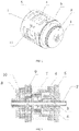
FIG. 1 is an exploded structural view of a locking mechanism according to the present application;
FIG. 2 is a structural view of a locking mechanism according to the present application; and
FIG. 3 is a sectional structural view of a locking mechanism according to the present application,
wherein: 1. housing; 11. guide slot; 2. joint output shaft; 21. key mounting slot; 3. key; 4. threaded sleeve; 41. positioning hole; 5. friction disk; 6. spline; 7. threaded shaft; 8. rotary disk; 9. end cap; 10. scroll spring.
DETAILED DESCRIPTION OF THE EMBODIMENTS
The present application will be further described with reference to the drawings and specific embodiments to enable those skilled in the art to have better understanding and implement the present application, but the embodiments described herein are not intended to limit the protection scope of the present application.
As shown in the drawings, the present application provides a joint locking mechanism of a passive robotic arm, comprising: an output assembly, including a joint output shaft 2, and a friction disk 5 fixed to the joint output shaft 2; a braking assembly, including a threaded shaft 7 arranged coaxially with the joint output shaft 2, a threaded sleeve 4 threaded to the threaded shaft 7, a rotary disk 8 connected fixedly to the threaded shaft 7, an end cap 9 rotatable relative to the rotary disk 8, and a scroll spring 10 generating a rotational force on the threaded shaft 7. The scroll spring 10 has one end connected fixedly to the end cap 9 and the other end connected to the rotary disk 8 or the threaded shaft 7. The threaded sleeve 4 is abutted tightly against the friction disk 5. The mechanism further comprises a housing 1. The threaded sleeve 4 is positioned within the housing 1. The housing 1 is provided with a guide slot 11 extending along the joint output shaft 2. At least one positioning hole 41 is provided in the threaded sleeve 4. The mechanism further comprises a pin extending through the guide slot 11 with an end portion thereof inserted in the positioning hole 41. The joint output shaft 2 is provided with a key mounting slot 21. A key 3 is mounted within the key mounting slot 21. The key 3 is protruded relative to the surface of the joint output shaft 2. A spline 6 is further sleeved over the joint output shaft 2. The friction disk 5 is fixed to the joint output shaft 2 via the spline 6. The key 3 is used to prevent the spline 6 from sliding relative to the joint output shaft 2. The spline 6 can simplify installation and prevent the friction disk 5 from sliding relative to the joint output shaft 2. The rotary disk 8 is sleeved over an end portion of the threaded shaft 7 away from the joint output shaft 2. The threaded sleeve 4 is sleeved over an end portion of the threaded shaft 7 proximate to the joint output shaft 2. The end cap 9 is sleeved on the threaded shaft 7 and positioned between the rotary disk 8 and the threaded sleeve 4. The scroll spring 10 is positioned in the end cap 9 and sleeved over the threaded shaft 7. The end cap 9 is mounted fixedly on an end portion of the housing 1. The end portion of the threaded shaft 7 away from the joint output shaft 2 is rotatably mounted on the end cap 9. The joint output shaft 2 is rotatably mounted within the housing 1.
The joint locking mechanism of a passive robotic arm according to the present application is operated as follows: when there is no external force applied, the scroll spring 10 causes a tendency for the threaded shaft 7 to rotate, thereby causing a tendency for the threaded sleeve 4 fitted over the threaded shaft 7 to move towards the joint output shaft 2, so that the threaded sleeve 4 is pressed tightly against the friction disk 5, whereupon the friction disk 5 under pressure causes the joint output shaft 2 to be braked. When it is rotated under an external force, the rotary disk 8 drives the threaded shaft 7 to rotate in a direction opposite to the tendency of rotation in a stationary state and drives the threaded sleeve 4 to move away from the friction disk 5 along the joint output shaft 2, so as to release the friction disk 5 and allow the joint output shaft 2 to start rotating. When the external force is removed from the rotary disk 8, a rotational force is applied to the threaded shaft 7 by the scroll spring 10, causing the threaded shaft 7 to rotate in an opposite direction and drive the threaded sleeve 4 to move towards the friction disk 5 along the joint output shaft 2 and be pressed tightly against the friction disk 5 again, so that the joint output shaft 2 is braked. In this process, due to the pin, the threaded sleeve 4 can only move back and forth along the length of the guide slot and along the joint output shaft 2.
The joint locking mechanism of a passive robotic arm provided by the present application is used for medical surgeries to provide joint locking. When the external force is removed from the rotary disk 8, a rotational force is applied to the threaded shaft 7 by the scroll spring 10, causing the threaded shaft 7 to rotate in an opposite direction and drive the threaded sleeve 4 to move towards the friction disk 5 along the joint output shaft 2 and be pressed tightly against the friction disk 5 again, so that the joint output shaft 2 is braked. In this process, due to the pin, the threaded sleeve 4 is limited to only move back and forth along the length of the guide slot and along the joint output shaft 2.
The embodiments described above are merely preferred embodiments for thorough description of the application, and the scope of the application is not limited thereto. Equivalent substitutions or alterations made by those skilled in the art on the basis of this application shall fall within the scope of this application. The scope of this application is defined by the claims.

Claims (4)

What is claimed is:
1. A joint locking mechanism of a passive robotic arm, comprising:
an output assembly, including a joint output shaft, and a friction disk fixed to the joint output shaft;
a braking assembly, including a threaded shaft arranged coaxially with the joint output shaft, a threaded sleeve threaded to the threaded shaft, a rotary disk connected fixedly to the threaded shaft, an end cap rotatable relative to the rotary disk, and a scroll spring generating a rotational force on the threaded shaft, in which the scroll spring has a first end connected fixedly to the end cap and a second end connected to the rotary disk or the threaded shaft, and the threaded sleeve is abutted tightly against the friction disk; and
a housing, wherein the threaded sleeve is positioned within the housing, the housing is provided with a guide slot extending along the joint output shaft, and at least one positioning hole is provided in the threaded sleeve; the mechanism further comprising a pin extending through the guide slot with an end portion thereof inserted in the positioning hole.
2. The mechanism of claim 1, wherein the joint output shaft is provided with a key mounting slot, a key is mounted in the key mounting slot, the key is protruded relative to the surface of the joint output shaft, a spline is further sleeved over the joint output shaft, and the friction disk is fixed to the joint output shaft via the spline.
3. The mechanism of claim 1, wherein the rotary disk is sleeved over an end portion of the threaded shaft away from the joint output shaft, the threaded sleeve is sleeved over an end portion of the threaded shaft proximate to the joint output shaft, the end cap is sleeved on the threaded shaft and positioned between the rotary disk and the threaded sleeve, and the scroll spring is positioned in the end cap and sleeved over the threaded shaft.
4. The mechanism of claim 1, wherein the end cap is mounted fixedly on an end portion of the housing, the end portion of the threaded shaft away from the joint output shaft is rotatably mounted on the end cap, and the joint output shaft is rotatably mounted in the housing.
US16/320,043 2017-12-29 2018-01-17 Joint locking mechanism of passive robotic arm Active 2040-01-21 US11364083B2 (en)

Applications Claiming Priority (3)

Application Number Priority Date Filing Date Title
CN201711483123.5A CN108000553B (en) 2017-12-29 2017-12-29 A kind of passive joint of mechanical arm retaining mechanism
CN201711483123.5 2017-12-29
PCT/CN2018/072932 WO2019127696A1 (en) 2017-12-29 2018-01-17 Passive robotic arm joint locking mechanism

Publications (2)

Publication Number Publication Date
US20210369358A1 US20210369358A1 (en) 2021-12-02
US11364083B2 true US11364083B2 (en) 2022-06-21

Family

ID=62049375

Family Applications (1)

Application Number Title Priority Date Filing Date
US16/320,043 Active 2040-01-21 US11364083B2 (en) 2017-12-29 2018-01-17 Joint locking mechanism of passive robotic arm

Country Status (3)

Country Link
US (1) US11364083B2 (en)
CN (1) CN108000553B (en)
WO (1) WO2019127696A1 (en)

Families Citing this family (5)

* Cited by examiner, † Cited by third party
Publication number Priority date Publication date Assignee Title
CN108327149B (en) * 2018-02-12 2020-06-23 江南大学 Glove transportation and gum dipping solidification drying device
CN108407172B (en) * 2018-02-12 2020-06-19 江南大学 Conveying hand former and assembly device of gloves production usefulness
CN108394056B (en) * 2018-02-12 2020-06-23 江南大学 A push glove mouth opening assembly and gluing curing device
CN109623773B (en) * 2018-12-28 2019-12-10 盐城市沿海新能源汽车科技有限公司 Carry on intelligent vision carrier of arm
CN116658774A (en) * 2023-06-09 2023-08-29 成都科奥达光电技术有限公司 Electromagnetic two-dimensional connecting arm

Citations (9)

* Cited by examiner, † Cited by third party
Publication number Priority date Publication date Assignee Title
US4065100A (en) * 1976-02-05 1977-12-27 Eaton Corporation Hoist load brake
US4804150A (en) * 1986-07-30 1989-02-14 Daiwa Seiko, Inc. Apparatus for measuring the drag-force of a fishing reel
CN201537927U (en) 2009-11-03 2010-08-04 昆山市工业技术研究院有限责任公司 An Electric Locking Rotary Joint for Surgical Operation Auxiliary Arm
CN102672718A (en) 2012-05-03 2012-09-19 上海交通大学 One-key locked passive seven-degree-of-freedom mechanical arm
CN202943645U (en) 2012-10-12 2013-05-22 上海交通大学 Passive type one-key dead-lock seven-freedom mechanical arm
CN103622751A (en) 2013-12-18 2014-03-12 哈尔滨工业大学 Surgical robot passive joint based on motor drive locking
JP2014228040A (en) 2013-05-21 2014-12-08 セイコーエプソン株式会社 Electromagnetic brake and robot
JP2015100878A (en) 2013-11-25 2015-06-04 ヤマハ発動機株式会社 Non-excitation electromagnetic brake for industrial robot
CN206780439U (en) 2017-05-11 2017-12-22 华志微创医疗科技(北京)有限公司 A kind of mechanical arm that clutch is used for joint locking

Family Cites Families (1)

* Cited by examiner, † Cited by third party
Publication number Priority date Publication date Assignee Title
CN207858880U (en) * 2017-12-29 2018-09-14 苏州大学 A kind of passive joint of mechanical arm retaining mechanism

Patent Citations (9)

* Cited by examiner, † Cited by third party
Publication number Priority date Publication date Assignee Title
US4065100A (en) * 1976-02-05 1977-12-27 Eaton Corporation Hoist load brake
US4804150A (en) * 1986-07-30 1989-02-14 Daiwa Seiko, Inc. Apparatus for measuring the drag-force of a fishing reel
CN201537927U (en) 2009-11-03 2010-08-04 昆山市工业技术研究院有限责任公司 An Electric Locking Rotary Joint for Surgical Operation Auxiliary Arm
CN102672718A (en) 2012-05-03 2012-09-19 上海交通大学 One-key locked passive seven-degree-of-freedom mechanical arm
CN202943645U (en) 2012-10-12 2013-05-22 上海交通大学 Passive type one-key dead-lock seven-freedom mechanical arm
JP2014228040A (en) 2013-05-21 2014-12-08 セイコーエプソン株式会社 Electromagnetic brake and robot
JP2015100878A (en) 2013-11-25 2015-06-04 ヤマハ発動機株式会社 Non-excitation electromagnetic brake for industrial robot
CN103622751A (en) 2013-12-18 2014-03-12 哈尔滨工业大学 Surgical robot passive joint based on motor drive locking
CN206780439U (en) 2017-05-11 2017-12-22 华志微创医疗科技(北京)有限公司 A kind of mechanical arm that clutch is used for joint locking

Also Published As

Publication number Publication date
CN108000553B (en) 2019-11-05
US20210369358A1 (en) 2021-12-02
CN108000553A (en) 2018-05-08
WO2019127696A1 (en) 2019-07-04

Similar Documents

Publication Publication Date Title
US11364083B2 (en) Joint locking mechanism of passive robotic arm
US10898293B2 (en) Medical support arm device and medical system
JP6999541B2 (en) Powered support arm that can be quickly repositioned
US8074657B2 (en) Surgical drape system
CN101380249B (en) An arrangement for manipulating a medical device
CN103533908A (en) Instrument interface
JP2005098957A (en) Arm mechanism of simulated human body for collision test
CN113116404A (en) Double-parallelogram RCM mechanism and minimally invasive surgery robot with same
JP2018020004A (en) Medical instrument gripping mechanism
US12318163B2 (en) Strain wave gearing with input to output braking
CN104758052B (en) Position and posture adjusting passive manipulator for digestive endoscopy conveying robot
CN115721246A (en) Endoscope transmission device and surgical robot
WO2023124946A1 (en) Guide wire or catheter controller and surgical robot
CN101822865B (en) Intervention operation catheter clamping jaw with dual force feedback function
CN112336390A (en) Device for simultaneously securing medical instruments and corresponding system
CN116269802A (en) Surgical instruments and surgical robots
CN104188709B (en) A kind of multi-angle for surgical operation robot is from hands tweezers
CN209564207U (en) A kind of operating robot
CN108015800B (en) Joint locking mechanism
CN219089645U (en) Main hand opening and closing components and surgical robots
WO2016132689A1 (en) Medical support arm device and medical system
CN207858880U (en) A kind of passive joint of mechanical arm retaining mechanism
CN117338443A (en) Medical instrument box, robot ultrasonic knife and surgical robot
CN116972282A (en) A brake assembly, a sliding platform with a horizontal telescopic arm and a surgical robot
CN223773812U (en) Suture instrument for surgical robot

Legal Events

Date Code Title Description
AS Assignment

Owner name: SOOCHOW UNIVERSITY, CHINA

Free format text: ASSIGNMENT OF ASSIGNORS INTEREST;ASSIGNORS:KUANG, SHAOLONG;LI, JINZHONG;ZHANG, LI;AND OTHERS;SIGNING DATES FROM 20190118 TO 20190123;REEL/FRAME:048117/0367

FEPP Fee payment procedure

Free format text: ENTITY STATUS SET TO UNDISCOUNTED (ORIGINAL EVENT CODE: BIG.); ENTITY STATUS OF PATENT OWNER: SMALL ENTITY

FEPP Fee payment procedure

Free format text: ENTITY STATUS SET TO SMALL (ORIGINAL EVENT CODE: SMAL); ENTITY STATUS OF PATENT OWNER: SMALL ENTITY

STPP Information on status: patent application and granting procedure in general

Free format text: NON FINAL ACTION MAILED

STPP Information on status: patent application and granting procedure in general

Free format text: NOTICE OF ALLOWANCE MAILED -- APPLICATION RECEIVED IN OFFICE OF PUBLICATIONS

STPP Information on status: patent application and granting procedure in general

Free format text: PUBLICATIONS -- ISSUE FEE PAYMENT VERIFIED

STCF Information on status: patent grant

Free format text: PATENTED CASE

MAFP Maintenance fee payment

Free format text: PAYMENT OF MAINTENANCE FEE, 4TH YR, SMALL ENTITY (ORIGINAL EVENT CODE: M2551); ENTITY STATUS OF PATENT OWNER: SMALL ENTITY

Year of fee payment: 4