US11346189B2 - Method and apparatus for expanding wellbore casing - Google Patents
Method and apparatus for expanding wellbore casing Download PDFInfo
- Publication number
- US11346189B2 US11346189B2 US16/768,853 US201816768853A US11346189B2 US 11346189 B2 US11346189 B2 US 11346189B2 US 201816768853 A US201816768853 A US 201816768853A US 11346189 B2 US11346189 B2 US 11346189B2
- Authority
- US
- United States
- Prior art keywords
- assembly
- expandable
- expandable liner
- cone
- jack
- Prior art date
- Legal status (The legal status is an assumption and is not a legal conclusion. Google has not performed a legal analysis and makes no representation as to the accuracy of the status listed.)
- Active, expires
Links
Images


Classifications
-
- E—FIXED CONSTRUCTIONS
- E21—EARTH OR ROCK DRILLING; MINING
- E21B—EARTH OR ROCK DRILLING; OBTAINING OIL, GAS, WATER, SOLUBLE OR MELTABLE MATERIALS OR A SLURRY OF MINERALS FROM WELLS
- E21B43/00—Methods or apparatus for obtaining oil, gas, water, soluble or meltable materials or a slurry of minerals from wells
- E21B43/02—Subsoil filtering
- E21B43/10—Setting of casings, screens, liners or the like in wells
- E21B43/103—Setting of casings, screens, liners or the like in wells of expandable casings, screens, liners, or the like
- E21B43/105—Expanding tools specially adapted therefor
-
- E—FIXED CONSTRUCTIONS
- E21—EARTH OR ROCK DRILLING; MINING
- E21B—EARTH OR ROCK DRILLING; OBTAINING OIL, GAS, WATER, SOLUBLE OR MELTABLE MATERIALS OR A SLURRY OF MINERALS FROM WELLS
- E21B43/00—Methods or apparatus for obtaining oil, gas, water, soluble or meltable materials or a slurry of minerals from wells
- E21B43/02—Subsoil filtering
- E21B43/10—Setting of casings, screens, liners or the like in wells
- E21B43/103—Setting of casings, screens, liners or the like in wells of expandable casings, screens, liners, or the like
- E21B43/106—Couplings or joints therefor
Definitions
- This disclosure relates generally to methods and apparatus for expanding wellbore tubular members, such as casing, liners, and the like. More specifically, this disclosure relates to methods and apparatus for expanding a first section of expandable tubular to an inside diameter that allows a second section of expandable tubular and expansion assembly to pass through the previously expanded section and then be expanded to the same inside diameter.
- expandable tubing is often used for casing, liners and the like.
- a tubular member is installed in a wellbore and subsequently expanded by displacing an expansion cone through the tubular member.
- the expansion cone may be pushed or pulled using mechanical means, such as by a support tubular coupled thereto, or driven by hydraulic pressure.
- the expansion cone imparts radial force to the inner surface of the tubular member.
- the tubular member plastically deforms, thereby permanently increasing both its inner and outer diameters.
- the tubular member expands radially.
- Expandable tubulars may also be used to repair, seal, or remediate existing casing that has been perforated, parted, corroded, or otherwise damaged since installation.
- the disclosure describes a system for expanding an expandable liner.
- the expandable system may comprise a cone assembly, which may be disposed within the expandable liner.
- the cone assembly may be moveable between a retracted position and an extended position. Axial movement of the cone assembly set in the extended position through the expandable liner may radially expand the expandable liner.
- the expandable system may comprise a jack assembly, which may be disposed within the expandable liner and may be coupled to the cone assembly.
- the jack assembly may be operable to move the cone assembly from the retracted position to the extended position.
- the jack assembly may comprise an upper coupling operable to lock the jack assembly until a fluid pumped into the expandable system reaches a predetermined pressure.
- the upper coupling may comprise a piston sleeve operable to move from a first position urging dogs toward the jack assembly and a second position permitting the dogs to move radially outward, and one or more pins configured to shear upon the fluid applying the predetermined pressure on the piston sleeve.
- the expandable system may comprise a latch assembly, which may be disposed within the expandable liner and may be coupled to the jack assembly and the cone assembly.
- the latch assembly may be operable to releasably couple the jack assembly and the cone assembly to the expandable liner.
- the latch assembly may comprise one or more latch dogs operable to move radially inward and disengage one or more corresponding receptacles formed on the inner surface of the expandable liner.
- the latch assembly may be operable to release the jack assembly and the cone assembly from the expandable liner upon the cone assembly reaching the extended position.
- the latch assembly may comprise one or more latch dogs operable to engage one or more corresponding receptacles formed on the inner surface of the expandable liner; the jack assembly may further comprise a release groove that registers with the one or more latch dogs upon the cone assembly reaching the extended position; and, the one or more latch dogs may be operable to move radially inward and disengage the expandable liner upon the release groove registering with the one or more latch dogs.
- the jack assembly may further be operable to retain the cone assembly in the extended position.
- the one or more latch dogs may be operable to move radially inward and engage the release groove upon the release groove registering with the one or more latch dogs.
- some other means may be used to retain the cone assembly in the extended position, such as a ratcheting lock ring disposed between a body and a mandrel of the jack assembly.
- the expandable system may comprise expansion cup seals, which may be coupled to the jack assembly.
- the expansion cup seals may be operable to move the cone assembly set in the extended position through the expandable liner and cause radial expansion of the expandable liner.
- the disclosure also describes a method for expanding a liner.
- the method may involve coupling an expansion tool to an expandable liner with a latch assembly.
- the expansion tool may include a cone assembly, a jack assembly, and the latch assembly.
- the method may involve disposing the expansion tool and expandable liner into a wellbore.
- the method may involve locking the jack assembly until a fluid pumped into the expandable system reaches a predetermined pressure.
- the method may further involve moving the cone assembly from a retracted position to an extended position using the jack assembly.
- the latch assembly may maintain the coupling between the expansion assembly and the expandable liner while the cone assembly is moving from the retracted position to the extended position.
- the method may involve releasing the latch assembly so as to decouple the expansion tool from the expandable liner once the cone assembly is fully moved to the extended position.
- the method may further involve retaining the cone assembly in the extended position once the cone assembly is fully moved to the extended position.
- the method may involve moving the cone assembly through the expandable liner without using the jack assembly, wherein moving the cone assembly radially expands the expandable liner.
- the moving of the cone assembly through the expandable liner may be performed by applying fluid pressure on expansion cup seals coupled to the jack assembly.
- FIGS. 1A-1B illustrate one embodiment of an expansion assembly including an expandable casing and an expansion assembly
- FIGS. 2A-2D illustrate the installation of an expandable using the expansion assembly of FIGS. 1A-1B ;
- FIGS. 3A-3C illustrate one embodiment of an expansion cone moving from a retracted position to an extended position
- FIG. 4 illustrates one embodiment of an expansion cone being moved from an extended position to a retracted position.
- first and second features are formed in direct contact
- additional features may be formed interposing the first and second features, such that the first and second features may not be in direct contact.
- exemplary embodiments presented below may be combined in any combination of ways, i.e., any element from one exemplary embodiment may be used in any other exemplary embodiment, without departing from the scope of the disclosure.
- an expandable system 100 includes an expansion assembly 102 and an expandable liner 104 (shown in cutaway view).
- the expansion assembly 102 includes a cone assembly 106 , latch assembly 108 , expansion cup seals 110 , jack assembly 112 , safety sub 114 , and debris catcher 116 , and the expansion assembly 102 is connected to running string 118 .
- the expansion assembly 102 is disposed within the expandable liner 104 , which includes a shoe assembly 120 , lower casing 122 , latch casing 124 , anchor casing 126 , and upper casing 128 .
- each of the lower casing 122 , latch casing 124 , anchor casing 126 , and upper casing 128 are formed from expandable tubulars connected to one another by a series of expandable threaded connections.
- the expansion assembly 102 is disposed within the expandable liner 104 such that the cone assembly 106 is engaged with the shoe assembly 120 .
- the latch assembly 108 includes one or more latch dogs 130 that protrude from the outer surface of the latch assembly so as to engage a corresponding receptacle 132 formed on the inner surface of the latch casing 124 .
- the latch dogs 130 may include a threaded or grooved outer surface that engages with corresponding threads or grooves that form the receptacle 132 . The engagement of the dogs 130 and receptacle 132 axially couples the expansion assembly 102 to the expandable liner 104 as the expandable system 100 is run into a wellbore.
- FIG. 2A shows the expansion assembly 102 in a running configuration where dogs 130 are engaged with receptacle 132 and cone assembly 106 is in a collapsed position.
- a dart 20 is dropped from the surface, through the running string 118 and expansion assembly 102 to engage the shoe assembly 120 .
- the dart 20 blocks the flow of fluid through the shoe assembly 120 so that pressurized fluid is contained within the expandable liner 104 and within the expansion assembly 102 .
- the activated jack assembly 112 causes the cone assembly 106 to shift from a collapsed position to an extended position as is shown in FIG. 2B .
- the engagement of the dogs 130 and receptacle 132 maintain the position of the expansion assembly 102 within the expandable liner 104 as the jack assembly 112 actuates to shift the cone assembly 106 .
- the cone assembly 106 As the cone assembly 106 is moved to the extended position, the cone assembly radially expands the lower casing 122 .
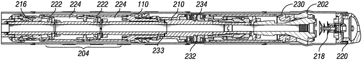
- FIGS. 3A and 3B show a sectional view of one embodiment of an expandable system 200 so as to illustrate the shifting of a cone assembly 202 from a collapsed position ( FIG. 3A ) to an extended position ( FIG. 3B ) using a jack assembly 204 .
- Cone assembly 202 includes a tapered mandrel 206 and a plurality of cone segments 208 .
- the tapered mandrel 206 is coupled to a jack mandrel 210 via lower coupling 212 .
- Pistons 222 are coupled to the jack mandrel 210 and disposed within pressure chambers 224 formed by jack body 226 . In the running position shown in FIG.
- the jack mandrel 210 is coupled to jack body 226 by upper coupling 216 .
- jack mandrel 210 is rotationally secured to the jack body 226 by splines 228 and grooves 23 as shown in FIG. 3C or other features as are known in the art.
- a dart 218 (or other sealing member) is pumped through the jack mandrel 210 and lands in shoe assembly 220 so as to prevent fluid from passing from the jack mandrel through the shoe assembly.
- upper coupling 216 releases and the jack mandrel 210 is free to move axially relative to the jack body 226 .
- upper coupling 216 may comprise a piston sleeve, dogs engaged with the jack mandrel 210 , and one or more shear pins.
- One side of the piston sleeve may be in pressure communication with the bore of the jack mandrel 210 via passageways provided across a wall of the jack mandrel 210 and across a wall of the jack body 226 , and the other side of the piston sleeve may be in pressure communication with the wellbore.
- pressure chambers 224 which act against pistons 222 to apply an axial load to the jack mandrel 210 .
- the pressure chambers 224 that are located on one side of the pistons 222 may be in pressure communication with the bore of the jack mandrel 210 via passageways provided across a wall of the jack mandrel 210 .
- the pressure chambers that are located on the other side of the pistons 222 e.g., the left side as illustrated in FIGS.
- 3A and 3B may be in pressure communication with the wellbore via passageways provided across a wall of the jack body 226 .
- the jack mandrel will move axially relative to jack body 226 and the tapered mandrel 206 will move axially relative to the cone segments 208 and move the cone segments outward to radially expand tubular member 230 .
- tubular member 230 is axially fixed to the jack body 226 via dogs 232 .
- a release groove 234 on jack mandrel 210 engage dogs 232 and allows the dogs to move radially inward and disengage the tubular member 230 .
- the engagement of dogs 232 and release groove 234 also acts to again axially couple the jack mandrel 210 to the jack body 226 .
- a ratcheting lock ring 233 or similar single-directional locking mechanism could be engaged to the jack mandrel 210 to the jack body 226 at the same time to retain the cone assembly 202 in the extended position.
- the ratcheting lock ring 233 may include a cylindrical body split by a single longitudinal cut, and a fine buttress or sawtooth shaped thread on one of the inner or outer diameter of the cylindrical body and a coarse buttress or sawtooth shaped thread on the other of the inner or outer diameter.
- This split cylindrical body may be provided between the jack mandrel 210 to the jack body 226 .
- the buttress or sawtooth shaped thread on the ratcheting lock ring 233 are oriented such that relative movement between the jack mandrel 210 to the jack body 226 is allowed in one direction (e.g., the jack mandrel 210 moving toward the left side as illustrated between FIGS.
- any other single-directional locking mechanism may be used, such as spring-loaded parts that are axially constrained within one body and include a sawtooth profile configured to engage an opposing sawtooth profile on the other body in order to lock up relative movement in one direction only, for example, a socket wrench.
- tapered mandrel 206 may include a sealing shoulder 300 that is configured to engage a ball 302 , or other sealing member, that can be pumped into position via jack mandrel 210 .
- a sealing shoulder 300 that is configured to engage a ball 302 , or other sealing member, that can be pumped into position via jack mandrel 210 .
- ball 302 engaged with shoulder 300
- continued supply of pressurized fluid to jack mandrel 210 will apply an axial load to the lower coupling 212 .
- the lower coupling 212 will release, allowing the tapered mandrel 206 to move axially away from the jack mandrel 210 .
- This axial movement allows the cone segments 208 to move along tapered mandrel 206 toward their collapsed position.
- This functionality may be especially beneficial should the cone assembly 202 becomes stuck in the tubular member (not shown) or to reduce the outer diameter of the cone assembly so as to simplify recovery following expansion operations.
Landscapes
- Geology (AREA)
- Life Sciences & Earth Sciences (AREA)
- Engineering & Computer Science (AREA)
- Mining & Mineral Resources (AREA)
- Environmental & Geological Engineering (AREA)
- Fluid Mechanics (AREA)
- Physics & Mathematics (AREA)
- General Life Sciences & Earth Sciences (AREA)
- Geochemistry & Mineralogy (AREA)
- Pressure Vessels And Lids Thereof (AREA)
- Earth Drilling (AREA)
- Quick-Acting Or Multi-Walled Pipe Joints (AREA)
- Joints Allowing Movement (AREA)
- Spinning Or Twisting Of Yarns (AREA)
Abstract
Description
Claims (25)
Priority Applications (1)
| Application Number | Priority Date | Filing Date | Title |
|---|---|---|---|
| US16/768,853 US11346189B2 (en) | 2017-12-01 | 2018-11-15 | Method and apparatus for expanding wellbore casing |
Applications Claiming Priority (3)
| Application Number | Priority Date | Filing Date | Title |
|---|---|---|---|
| US201762593518P | 2017-12-01 | 2017-12-01 | |
| US16/768,853 US11346189B2 (en) | 2017-12-01 | 2018-11-15 | Method and apparatus for expanding wellbore casing |
| PCT/US2018/061303 WO2019108405A1 (en) | 2017-12-01 | 2018-11-15 | Method and apparatus for expanding wellbore casing |
Publications (2)
| Publication Number | Publication Date |
|---|---|
| US20210189843A1 US20210189843A1 (en) | 2021-06-24 |
| US11346189B2 true US11346189B2 (en) | 2022-05-31 |
Family
ID=66665760
Family Applications (1)
| Application Number | Title | Priority Date | Filing Date |
|---|---|---|---|
| US16/768,853 Active 2039-01-22 US11346189B2 (en) | 2017-12-01 | 2018-11-15 | Method and apparatus for expanding wellbore casing |
Country Status (6)
| Country | Link |
|---|---|
| US (1) | US11346189B2 (en) |
| AU (1) | AU2018374755B2 (en) |
| GB (1) | GB2582483B (en) |
| MX (1) | MX2020005676A (en) |
| NO (1) | NO20200638A1 (en) |
| WO (1) | WO2019108405A1 (en) |
Citations (14)
| Publication number | Priority date | Publication date | Assignee | Title |
|---|---|---|---|---|
| US3011555A (en) * | 1958-04-14 | 1961-12-05 | Baker Oil Tools Inc | Well packers |
| US20050056433A1 (en) * | 2001-11-12 | 2005-03-17 | Lev Ring | Mono diameter wellbore casing |
| US20060102360A1 (en) | 1998-12-07 | 2006-05-18 | Brisco David P | System for radially expanding a tubular member |
| US20090065196A1 (en) | 2007-09-11 | 2009-03-12 | Enventure Global Technology, Llc | Methods and Apparatus for Anchoring and Expanding Tubular Members |
| US20110011578A1 (en) | 2009-07-15 | 2011-01-20 | Enventure Global Technology, Llc | Expansion System for Expandable Tubulars |
| US20120152565A1 (en) | 2010-12-21 | 2012-06-21 | Enventure Global Technology, L.L.C. | Downhole release joint with radially expandable member |
| US20130333873A1 (en) | 2008-05-05 | 2013-12-19 | Weatherford/Lamb, Inc. | Tools and methods for hanging and/or expanding liner strings |
| US20140027118A1 (en) | 2012-07-30 | 2014-01-30 | Richard W. DeLange | Expandable liner |
| US20150013971A1 (en) | 2011-01-07 | 2015-01-15 | Weatherford Technology Holdings, LLC. | Test packer and method for use |
| US9085967B2 (en) | 2012-05-09 | 2015-07-21 | Enventure Global Technology, Inc. | Adjustable cone expansion systems and methods |
| US20150315882A1 (en) | 2014-05-05 | 2015-11-05 | Enventure Global Technology, Inc. | Expansion system |
| WO2017001391A1 (en) | 2015-07-01 | 2017-01-05 | Shell Internationale Research Maatschappij B.V. | Hybrid push and pull method and system for expanding well tubulars |
| US20170284176A1 (en) | 2014-09-15 | 2017-10-05 | Enventure Global Technology, Llc | Expansion system |
| US20170342811A1 (en) | 2016-05-31 | 2017-11-30 | Tiw Corporation | Downhole Tubular Expansion Tool and Method for Installing a Tandem Clad Liner |
-
2018
- 2018-11-15 AU AU2018374755A patent/AU2018374755B2/en not_active Ceased
- 2018-11-15 MX MX2020005676A patent/MX2020005676A/en unknown
- 2018-11-15 GB GB2008134.5A patent/GB2582483B/en active Active
- 2018-11-15 WO PCT/US2018/061303 patent/WO2019108405A1/en not_active Ceased
- 2018-11-15 US US16/768,853 patent/US11346189B2/en active Active
-
2020
- 2020-05-29 NO NO20200638A patent/NO20200638A1/en unknown
Patent Citations (15)
| Publication number | Priority date | Publication date | Assignee | Title |
|---|---|---|---|---|
| US3011555A (en) * | 1958-04-14 | 1961-12-05 | Baker Oil Tools Inc | Well packers |
| US20060102360A1 (en) | 1998-12-07 | 2006-05-18 | Brisco David P | System for radially expanding a tubular member |
| US20050056433A1 (en) * | 2001-11-12 | 2005-03-17 | Lev Ring | Mono diameter wellbore casing |
| US20090065196A1 (en) | 2007-09-11 | 2009-03-12 | Enventure Global Technology, Llc | Methods and Apparatus for Anchoring and Expanding Tubular Members |
| US20130333873A1 (en) | 2008-05-05 | 2013-12-19 | Weatherford/Lamb, Inc. | Tools and methods for hanging and/or expanding liner strings |
| US20110011578A1 (en) | 2009-07-15 | 2011-01-20 | Enventure Global Technology, Llc | Expansion System for Expandable Tubulars |
| US20120152565A1 (en) | 2010-12-21 | 2012-06-21 | Enventure Global Technology, L.L.C. | Downhole release joint with radially expandable member |
| US20150013971A1 (en) | 2011-01-07 | 2015-01-15 | Weatherford Technology Holdings, LLC. | Test packer and method for use |
| US9085967B2 (en) | 2012-05-09 | 2015-07-21 | Enventure Global Technology, Inc. | Adjustable cone expansion systems and methods |
| US20140027118A1 (en) | 2012-07-30 | 2014-01-30 | Richard W. DeLange | Expandable liner |
| US20150315882A1 (en) | 2014-05-05 | 2015-11-05 | Enventure Global Technology, Inc. | Expansion system |
| US20170284176A1 (en) | 2014-09-15 | 2017-10-05 | Enventure Global Technology, Llc | Expansion system |
| WO2017001391A1 (en) | 2015-07-01 | 2017-01-05 | Shell Internationale Research Maatschappij B.V. | Hybrid push and pull method and system for expanding well tubulars |
| US20180119527A1 (en) * | 2015-07-01 | 2018-05-03 | Shell Oil Company | Hybrid push and pull method and system for expanding well tubulars |
| US20170342811A1 (en) | 2016-05-31 | 2017-11-30 | Tiw Corporation | Downhole Tubular Expansion Tool and Method for Installing a Tandem Clad Liner |
Non-Patent Citations (2)
| Title |
|---|
| UKIPO, Examination report issued in corresponding application serial No. GB 2008134.5 dated Nov. 22, 2021; 4 pages. |
| Written Opinion of the International Searching Authority in international application PCT/US2018/061303 dated Jan. 28, 2019, 7 pages. |
Also Published As
| Publication number | Publication date |
|---|---|
| NO20200638A1 (en) | 2020-05-29 |
| GB202008134D0 (en) | 2020-07-15 |
| AU2018374755B2 (en) | 2022-10-13 |
| GB2582483B (en) | 2022-06-22 |
| MX2020005676A (en) | 2020-11-24 |
| WO2019108405A1 (en) | 2019-06-06 |
| AU2018374755A1 (en) | 2020-06-18 |
| GB2582483A (en) | 2020-09-23 |
| US20210189843A1 (en) | 2021-06-24 |
Similar Documents
| Publication | Publication Date | Title |
|---|---|---|
| US8726985B2 (en) | Expanding a tubular element in a wellbore | |
| US8100186B2 (en) | Expansion system for expandable tubulars and method of expanding thereof | |
| US9366117B2 (en) | Method and system for lining a section of a wellbore with an expandable tubular element | |
| US11773671B2 (en) | Expandable liner hanger system and methodology | |
| US11965391B2 (en) | Downhole tool with sealing ring | |
| US10745979B2 (en) | Expandable drillable shoe | |
| US10502034B2 (en) | Expansion cone with rotational lock | |
| US11346189B2 (en) | Method and apparatus for expanding wellbore casing | |
| US10012058B2 (en) | Expansion system | |
| WO2014207085A1 (en) | Patch setting tool | |
| EP2818627A1 (en) | Patch for tubular and patch setting tool | |
| US9765598B2 (en) | Expansion system | |
| US10450845B2 (en) | Expanding a tubular element in a wellbore |
Legal Events
| Date | Code | Title | Description |
|---|---|---|---|
| FEPP | Fee payment procedure |
Free format text: ENTITY STATUS SET TO UNDISCOUNTED (ORIGINAL EVENT CODE: BIG.); ENTITY STATUS OF PATENT OWNER: LARGE ENTITY |
|
| AS | Assignment |
Owner name: ENVENTURE GLOBAL TECHNOLOGY, INC., TEXAS Free format text: ASSIGNMENT OF ASSIGNORS INTEREST;ASSIGNORS:YEE, CHEE KONG;BENNETT, FREDERICK CORNELL;SIGNING DATES FROM 20180110 TO 20180125;REEL/FRAME:053568/0945 Owner name: ENVENTURE GLOBAL TECHNOLOGY, INC., TEXAS Free format text: ASSIGNMENT OF ASSIGNORS INTEREST;ASSIGNORS:YEE, CHEE KONG;BENNETT, FREDERICK CORNELL;SIGNING DATES FROM 20180110 TO 20180125;REEL/FRAME:053568/0954 Owner name: ENVENTURE GLOBAL TECHNOLOGY, INC., TEXAS Free format text: ASSIGNMENT OF ASSIGNORS INTEREST;ASSIGNORS:CONNOR, ERIC J.;GODFREY, MATTHEW MARK;REEL/FRAME:053568/0958 Effective date: 20190129 |
|
| STPP | Information on status: patent application and granting procedure in general |
Free format text: DOCKETED NEW CASE - READY FOR EXAMINATION |
|
| STPP | Information on status: patent application and granting procedure in general |
Free format text: NON FINAL ACTION MAILED |
|
| STPP | Information on status: patent application and granting procedure in general |
Free format text: NOTICE OF ALLOWANCE MAILED -- APPLICATION RECEIVED IN OFFICE OF PUBLICATIONS |
|
| STPP | Information on status: patent application and granting procedure in general |
Free format text: PUBLICATIONS -- ISSUE FEE PAYMENT VERIFIED |
|
| STCF | Information on status: patent grant |
Free format text: PATENTED CASE |
|
| MAFP | Maintenance fee payment |
Free format text: PAYMENT OF MAINTENANCE FEE, 4TH YEAR, LARGE ENTITY (ORIGINAL EVENT CODE: M1551); ENTITY STATUS OF PATENT OWNER: LARGE ENTITY Year of fee payment: 4 |