US11344331B2 - Automated hair restoration assembly - Google Patents
Automated hair restoration assembly Download PDFInfo
- Publication number
- US11344331B2 US11344331B2 US16/855,412 US202016855412A US11344331B2 US 11344331 B2 US11344331 B2 US 11344331B2 US 202016855412 A US202016855412 A US 202016855412A US 11344331 B2 US11344331 B2 US 11344331B2
- Authority
- US
- United States
- Prior art keywords
- dissector
- turret
- cylinder
- actuator
- motor
- Prior art date
- Legal status (The legal status is an assumption and is not a legal conclusion. Google has not performed a legal analysis and makes no representation as to the accuracy of the status listed.)
- Active, expires
Links
Images


Classifications
-
- A—HUMAN NECESSITIES
- A61—MEDICAL OR VETERINARY SCIENCE; HYGIENE
- A61B—DIAGNOSIS; SURGERY; IDENTIFICATION
- A61B17/00—Surgical instruments, devices or methods
- A61B17/32—Surgical cutting instruments
- A61B17/3205—Excision instruments
- A61B17/32053—Punch like cutting instruments, e.g. using a cylindrical or oval knife
-
- A—HUMAN NECESSITIES
- A61—MEDICAL OR VETERINARY SCIENCE; HYGIENE
- A61B—DIAGNOSIS; SURGERY; IDENTIFICATION
- A61B17/00—Surgical instruments, devices or methods
- A61B17/34—Trocars; Puncturing needles
- A61B17/3468—Trocars; Puncturing needles for implanting or removing devices, e.g. prostheses, implants, seeds, wires
-
- A—HUMAN NECESSITIES
- A61—MEDICAL OR VETERINARY SCIENCE; HYGIENE
- A61F—FILTERS IMPLANTABLE INTO BLOOD VESSELS; PROSTHESES; DEVICES PROVIDING PATENCY TO, OR PREVENTING COLLAPSING OF, TUBULAR STRUCTURES OF THE BODY, e.g. STENTS; ORTHOPAEDIC, NURSING OR CONTRACEPTIVE DEVICES; FOMENTATION; TREATMENT OR PROTECTION OF EYES OR EARS; BANDAGES, DRESSINGS OR ABSORBENT PADS; FIRST-AID KITS
- A61F2/00—Filters implantable into blood vessels; Prostheses, i.e. artificial substitutes or replacements for parts of the body; Appliances for connecting them with the body; Devices providing patency to, or preventing collapsing of, tubular structures of the body, e.g. stents
- A61F2/02—Prostheses implantable into the body
- A61F2/10—Hair or skin implants
-
- A—HUMAN NECESSITIES
- A61—MEDICAL OR VETERINARY SCIENCE; HYGIENE
- A61B—DIAGNOSIS; SURGERY; IDENTIFICATION
- A61B17/00—Surgical instruments, devices or methods
- A61B2017/00017—Electrical control of surgical instruments
- A61B2017/00115—Electrical control of surgical instruments with audible or visual output
-
- A—HUMAN NECESSITIES
- A61—MEDICAL OR VETERINARY SCIENCE; HYGIENE
- A61B—DIAGNOSIS; SURGERY; IDENTIFICATION
- A61B17/00—Surgical instruments, devices or methods
- A61B2017/00367—Details of actuation of instruments, e.g. relations between pushing buttons, or the like, and activation of the tool, working tip, or the like
- A61B2017/00398—Details of actuation of instruments, e.g. relations between pushing buttons, or the like, and activation of the tool, working tip, or the like using powered actuators, e.g. stepper motors, solenoids
-
- A—HUMAN NECESSITIES
- A61—MEDICAL OR VETERINARY SCIENCE; HYGIENE
- A61B—DIAGNOSIS; SURGERY; IDENTIFICATION
- A61B17/00—Surgical instruments, devices or methods
- A61B2017/00743—Type of operation; Specification of treatment sites
- A61B2017/00747—Dermatology
- A61B2017/00752—Hair removal or transplantation
Definitions
- the disclosure and prior art relates to hair restoration devices and more particularly pertains to a new hair restoration device for automating the process of performing a hair restoration procedure.
- An embodiment of the disclosure meets the needs presented above by generally comprising a control unit and a cylinder that is gripped during a hair restoration surgical procedure.
- An actuator is positioned within the cylinder and a turret unit is rotatably coupled to the cylinder.
- a plurality of cartridges is provided and a selected one of the cartridges is loadable into the turret unit.
- Each of the cartridges contains a respective one of a plurality of incising blades, a plurality of hair grafts or an alternating sequence of a plurality of said incising blades.
- the actuator passes through the respective tube and engages one of the incising blades or one of the hair grafts.
- each the incising blades make a respective incision and each of the hair grafts is inserted into the respective incision.
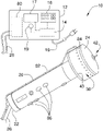
- FIG. 1 is a perspective view of a cylinder and a turret unit of an automated hair restoration assembly according to an embodiment of the disclosure.
- FIG. 2 is an exploded view of a cylinder and a turret unit of an embodiment of the disclosure.
- FIG. 3 is a phantom view of a cylinder and a turret unit of an embodiment of the disclosure.
- FIG. 4 is an exploded view of a turret unit and a graft cartridge of an embodiment of the disclosure.
- FIG. 5 is a top perspective view of a turret unit and an alternating cartridge of an embodiment of the disclosure.
- FIG. 6 is a front perspective view of a turret unit and graft cartridge of an embodiment of the disclosure.
- FIG. 7 is a phantom view of a sleeve containing an incising blade an embodiment of the disclosure.
- FIG. 8 is a phantom view of sleeve containing a hair graft of an embodiment of the disclosure.
- FIG. 9 is a schematic view of an embodiment of the disclosure.
- FIG. 10 is a perspective view of a plurality of cartridges of an embodiment of the disclosure.
- FIG. 11 is a perspective view of a dissector of an embodiment of the disclosure.
- FIG. 12 is an end view showing a dissector being rotated between a spreading position and a home position.
- FIGS. 1 through 10 With reference now to the drawings, and in particular to FIGS. 1 through 10 thereof, a new hair restoration device embodying the principles and concepts of an embodiment of the disclosure and generally designated by the reference numeral 11 will be described.
- the automated hair restoration assembly 10 generally comprises a control unit 12 that is positioned in a surgical room.
- the surgical room may be a room in which a hair restoration procedure is being performed.
- the control unit 12 includes a control circuit 14 and a power cord 16 that is electrically coupled to the control circuit 14 .
- the power cord 16 is electrically coupled to a power source, such as a female electrical outlet or the like.
- a control panel 18 is positioned on the control unit 12 , the control panel 18 is electrically coupled to the control circuit 14 and the control panel 18 controls operational parameters of the control circuit 14 .
- the control circuit 14 includes an electronic memory 15 that stores data pertaining to an incising configuration, a graft configuration and an implant configuration.
- a display 17 is coupled to the control unit 12 and the display 17 is electrically coupled to the control circuit 14 .
- the display 17 displays indicia comprising operational parameters, selected operational sequences, the number of incisions made or grafts inserted, and any other pertinent information for a user.
- the display 17 may comprise an LED or other type of electronic display.
- a speaker 19 is coupled to the control unit 12 for emitting audible alerts to the user.
- the speaker 19 is electrically coupled to the control circuit 14 and the speaker 19 may emit audible reminders relating to the operation of the control unit 12 .
- a cylinder 20 is provided and the cylinder 20 gripped during a hair restoration surgical procedure.
- the cylinder 20 has a first end 22 and a second end 24 , the cylinder 20 is hollow and the second end 24 is open.
- a conductor 26 is coupled between the first end 22 of the cylinder 20 and the control unit 12 and the conductor 26 is electrically coupled to the control circuit 14 .
- An actuator 28 is positioned within the cylinder 20 and the actuator 28 is electrically coupled to the conductor 26 .
- the actuator 28 is turned on to extend a pre-determined distance outwardly from the first end 22 of the cylinder 20 .
- the actuator 28 may be a linear actuator, an extending actuator, and actuator arm or other similar mechanical actuator that travels a fixed distance between an extended position and a returned position. Additionally, the fixed distance may the optimum depth of a hair graft incision for obtaining the maximum effective depth for insertion of a hair graft while minimizing trauma to underlying blood vessels and tissue.
- a turret motor 30 is positioned within the cylinder 20 and the turret motor 30 is electrically coupled to the conductor 26 .
- the turret motor 30 rotates a pre-determined degree of rotation in a first direction when the turret motor 30 is turned on.
- the turret motor 30 may be an electric motor or the like and the control circuit 14 controls the degree of rotation.
- a turret shaft 32 is movably coupled to the turret motor 30 , the turret shaft 32 has a distal end 34 with respect to the turret motor 30 and the distal end 34 is aligned with the second end 24 of the cylinder 20 .
- the turret motor 30 urges the turret shaft 32 into an extended position or a retracted position.
- a turret unit 36 is rotatably coupled to the cylinder 20 and the turret unit 36 has a plurality of tubes 38 that are distributed around a central shaft 40 .
- the turret unit 36 has a dissector 42 that is rotatably located thereon, the dissector 42 is distally positioned with respect to the cylinder 20 and the dissector 42 is aligned with the actuator 28 .
- the central shaft 40 engages the distal end 34 of the turret shaft 32 when the turret shaft 32 is urged into the extended position. In this way the turret unit 36 is retained in the cylinder 20 .
- An outer wall 41 of the cylinder 20 may have a turret opening 43 extending into an interior of the cylinder 20 and the turret opening 43 may insertably receive the turret unit 36 .
- the tubes 38 are oriented collinear with an axis extending through the first 22 and second 24 ends of the cylinder 20 when the turret unit 36 is coupled to the cylinder 20 .
- Each of the tubes 38 is sequentially aligned between the dissector 42 and the actuator 28 when the turret unit 36 is rotated.
- Each of the tubes 38 has a top end 44 and a bottom end 46 , and the top end 44 of a respective one of the tubes 38 is aligned with the actuator 28 each time the turret motor 30 is turned on.
- the bottom end 46 of the respective tube 38 is aligned with the dissector 42 each time the turret motor 30 is turned on.
- the top end 44 of the respective tube 38 receives the actuator 28 when the actuator 28 is turned on.
- the actuator 28 extends outwardly through the bottom end 46 of the respective tube 38 when the actuator 28 is turned on.
- the dissector 42 has a distal end 48 with respect to the turret unit 36 and an outer surface 50 .
- the dissector 42 is rotatable about an axis extending through the turret unit 36 and the distal end 48 of the dissector 42 .
- the distal end 48 of the dissector 42 is open, and dissector 42 includes a rounded portion 52 and a pair of fingers 54 each extending away from the rounded portion 52 .
- the fingers 54 are spaced apart from each other a distance that is greater than the thickness of the fingers 54 .
- the dissector 42 is rotatable between a home position and a spreading position. As is most clearly shown in FIG.
- the fingers 54 are rotated 90.0 degrees when the dissector 42 is rotated between the home position and the spreading position. In this way the dissector 42 can be inserted into the incision when the dissector 42 is in the home position and the dissector 42 spreads the incision when the dissector 42 is in the spreading position.
- a plurality of cartridges 60 is provided and selected one of the cartridges 60 is loadable into the turret unit 36 .
- Each of the cartridges 60 has a plurality of sleeves 62 therein that are arranged into a circle.
- the plurality of sleeves 62 in each of the cartridges 62 may contain an alternating sequence of a plurality of incising blades 64 and a plurality of hair grafts 66 .
- Each of the sleeves 62 has a fluid port 68 positioned thereon that is in fluid communication with an interior of the sleeves 62 .
- Each of the incising blades 64 may be scalpel blades or the like that are common to hair restoration procedures.
- Each of the incising blades 64 is biased to be retracted into the respective sleeve.
- each of the hair grafts 66 may be hair grafts commonly employed in hair restoration procedures.
- Each of the sleeves 62 is divided into a first section 56 that removably engages a second section 58
- the plurality of cartridges 60 includes an incising cartridge 61 , a graft cartridge 63 and an alternating cartridge 65 .
- the incising blades 64 extends through each of the first section 56 and the second section 58 of each of the sleeves 62 in the incising cartridge 61 .
- the first section 56 of each of the sleeves 62 in the graft cartridge 63 is loaded with the hair grafts 66 .
- each of the sleeves 62 in the alternating cartridge 65 is loaded with an alternating sequence of the incising blades 64 and the hair grafts 66 .
- Each of the incising blades has a length that is greater than the length of the sleeves 62 and each of the hair grafts 66 includes a plunger 67 . As is most clearly shown in FIG. 8 , the plunger 67 extends through the second section 58 of the sleeves 62 and the hair grafts 66 extending through the first section 56 of the sleeves 62 .
- Each of the sleeves 62 is aligned and is oriented collinear with a respective one of the tubes 38 when the selected cartridge 60 is loaded into the turret unit 36 .
- the actuator 28 passes through the respective tube 38 when the turret unit 36 is loaded into the turret opening 43 in the cylinder 20 and when the respective tube 38 is aligned with the actuator 28 .
- the actuator 28 engages one of the incising blades 64 or the plunger 67 on one of the hair grafts 66 thereby facilitating the incising blades 64 and the hair grafts 66 to be urged outwardly through the dissector 42 . In this way each the incising blades 64 can make a respective incision and each of the hair grafts 66 can be inserted into the respective incision.
- the incising cartridge 61 is loaded into the turret unit 36 for the first sequence, the graft cartridge 63 is loaded into the turret unit 36 for the second sequence and the alternating cartridge 65 is loaded into the turret unit 36 for the third sequence.
- the actuator 28 sequentially engages the incising blade 64 in each of the sleeves 62 when the incising cartridge is loaded into the turret unit 36 .
- the actuator 28 sequentially engages the plunger 67 of the hair graft 66 in each of the sleeves 62 when the graft cartridge 63 is loaded into the turret unit 36 .
- the actuator 28 engages, in an alternating sequence, the incising blade 64 and the plunger 67 of the hair graft 66 in each of the sleeves 62 when the alternating cartridge 65 is loaded into the turret unit 36 .
- the dissector 42 is urged into the respective incision when one of the incising blades 64 makes the respective incision having the dissector 42 being in the home position. Thus, the dissector 42 can subsequently guide the hair graft 66 into the respective incision.
- a blade sensor 70 is positioned within the dissector 42 and the blade sensor 70 is electrically coupled to the conductor 26 .
- the control circuit 14 in the control unit 12 receives a blade input when the blade sensor 70 senses one of the incising blades 64 has been urged into the dissector 42 .
- the blade sensor 70 may be a magnetic sensor or other electronic sensor that is capable of distinguishing between the incising blades 64 and the hair grafts 66 .
- a rotator motor 72 is positioned within the cylinder 20 and the rotator motor 72 is electrically coupled to the conductor 26 .
- the rotator motor 72 rotates a pre-determined distance away from a home position and then a corresponding distance back toward the home position when the rotator motor 72 is turned on. Additionally, the rotator motor 72 is turned on when the control circuit 14 receives the blade input.
- the rotator motor 72 may be an electric motor or the like.
- a rotator shaft 74 is rotatably coupled to the rotator motor 72 and the rotator shaft 74 has a distal end 76 .
- a gear 78 is coupled to the distal end 76 of the rotator shaft 74 and the gear 78 engages the rounded portion 52 of the outer surface 50 of the dissector 42 .
- the rotator motor 72 rotates the dissector 42 into the spreading position when the rotator motor 72 is turned on.
- the fingers 54 of the dissector 42 are rotated to spread the incision open to enhance the surgeon's ability to position the hair graft 66 within the respective incision.
- the rotator motor 72 rotates the dissector 42 back to the home position when the hair graft 66 has been inserted into the respective incision.
- the blade sensor 70 turns the rotator motor 72 on when the dissector 42 is pressed against the patient to rotate the dissector 42 into the spreading position.
- the blade sensor 70 turns the rotator motor 72 off when the dissector 42 is not pressed against the patient to rotate the dissector 42 into the home position. In this way the dissector 42 rotates into the spreading position and then into the home position each time the dissector 42 is pressed against the patient.
- a fluid pump 80 is positioned in the control unit 12 and the fluid pump 80 contains a liquid solution.
- the liquid solution may be saline or other liquid solution that would commonly be employed in the hair restoration procedure.
- the fluid pump 80 includes a fluid hose 82 that extends between the control unit 12 and the turret unit 36 .
- the fluid hose 82 has a distal end 84 with respect to the control unit 12 .
- the fluid port 68 on each of the sleeves 62 is aligned with the distal end 84 of the fluid hose 82 each time the turret unit 36 is rotated thereby facilitating the fluid pump 80 to urge the liquid solution into the incision for nourishing the hair graft 66 in the incision.
- a plurality of control buttons 86 is each of the control buttons 86 is movably coupled to the cylinder 20 and each of the control buttons 86 is electrically coupled to the conductor 26 .
- Each of the control buttons 86 is assigned to control operational parameters of a respective one of the actuator 28 , the turret motor 30 , the rotator motor 72 and the fluid pump 80 .
- the control circuit 14 contains data for a first sequence, a second sequence and a third sequence.
- the first sequence involves the turret unit 36 being rotated one place each time the turret motor 30 is turned on thereby lining up the incising blades 64 in the incising cartridge 61 with the actuator 28 .
- the actuator 28 makes repeated incisions during the hair restoration procedure.
- the second sequence involves the turret unit 36 being rotated one place each time the turret motor 30 is turned on. Additionally, the actuator 28 engages the plunger 67 of each of the hair grafts 66 when the graft cartridge 63 . In this way the actuator 28 inserts one of the hair grafts 66 into pre-made incisions. The dissector is rotated between the home position and the spreading position each time the actuator 28 engages the plunger 67 .
- the third sequence involves the turret unit 36 being rotated one place each time the turret motor 30 is turned on. Moreover, the fluid pump 80 is turned on each time the incision actuator 28 engages one of the hair grafts 66 .
- the hair graft 66 is moisturized or otherwise nourished when the hair graft 66 is inserted into the incision. Additionally, the rotator motor 72 is turned on each time the actuator 28 engages one of the incising blades 64 . Thus, the incision is spread open to ensure adequate penetration of the hair graft 66 into the incision.
- control panel 18 on the control unit 12 is manipulated to select the first sequence, the second sequence or the third sequence. Additionally, either the incising cartridge 61 , the graft cartridge 63 or the alternating cartridge 65 is loaded into the turret unit 36 .
- the cylinder 20 is gripped and the dissector 42 is positioned against the scalp for the hair restoration procedure.
- the turret unit 36 rotates one place each time the actuator 28 engages one of the incising blades 64 when the first sequence is selected.
- the process of making a plurality of incisions for a hair restoration procedure is automated.
- the turret unit 36 rotates one place each time the actuator 28 engages the plunger 67 of the hair grafts 66 in the cartridges 60 when the second sequence is selected. In this way the process of inserting a hair graft 66 into the incision is automated. Additionally, the fluid pump 80 can introduce the fluid into the incision once the hair graft 66 has been inserted into the incision when the third sequence is selected. In this way an individual surgeon can perform multiple steps in a hair restoration surgery with a single tool. The turret unit 36 rotates one place each time the actuator engages the alternating sequence of incising blades 64 and hair grafts 66 when the third sequence is selected. In this way the process of making an incision and inserting a hair graft 66 into the incision is automated.
Landscapes
- Health & Medical Sciences (AREA)
- Life Sciences & Earth Sciences (AREA)
- Surgery (AREA)
- Animal Behavior & Ethology (AREA)
- General Health & Medical Sciences (AREA)
- Engineering & Computer Science (AREA)
- Biomedical Technology (AREA)
- Heart & Thoracic Surgery (AREA)
- Veterinary Medicine (AREA)
- Public Health (AREA)
- Medical Informatics (AREA)
- Molecular Biology (AREA)
- Nuclear Medicine, Radiotherapy & Molecular Imaging (AREA)
- Transplantation (AREA)
- Pathology (AREA)
- Dermatology (AREA)
- Cardiology (AREA)
- Oral & Maxillofacial Surgery (AREA)
- Vascular Medicine (AREA)
- Surgical Instruments (AREA)
Abstract
Description
Claims (10)
Priority Applications (1)
| Application Number | Priority Date | Filing Date | Title |
|---|---|---|---|
| US16/855,412 US11344331B2 (en) | 2020-04-22 | 2020-04-22 | Automated hair restoration assembly |
Applications Claiming Priority (1)
| Application Number | Priority Date | Filing Date | Title |
|---|---|---|---|
| US16/855,412 US11344331B2 (en) | 2020-04-22 | 2020-04-22 | Automated hair restoration assembly |
Publications (2)
| Publication Number | Publication Date |
|---|---|
| US20210330353A1 US20210330353A1 (en) | 2021-10-28 |
| US11344331B2 true US11344331B2 (en) | 2022-05-31 |
Family
ID=78221002
Family Applications (1)
| Application Number | Title | Priority Date | Filing Date |
|---|---|---|---|
| US16/855,412 Active 2040-11-20 US11344331B2 (en) | 2020-04-22 | 2020-04-22 | Automated hair restoration assembly |
Country Status (1)
| Country | Link |
|---|---|
| US (1) | US11344331B2 (en) |
Citations (7)
| Publication number | Priority date | Publication date | Assignee | Title |
|---|---|---|---|---|
| US5782853A (en) | 1996-09-13 | 1998-07-21 | Zeevi; Eli I. | Surgical handle for surgical blades and punches |
| US6221088B1 (en) | 1996-09-24 | 2001-04-24 | Xomed Surgical Products, Inc. | Powered handpiece and surgical blades and methods thereof |
| US6432118B1 (en) | 1999-10-05 | 2002-08-13 | Ethicon Endo-Surgery, Inc. | Multifunctional curved blade for use with an ultrasonic surgical instrument |
| US20030036770A1 (en) * | 1995-02-28 | 2003-02-20 | Markman Barry S. | Device and method for inserting tissue anchor implants |
| USD568475S1 (en) | 2007-03-21 | 2008-05-06 | Sandel Medical Industries, Llc | Scalpel |
| US8715245B2 (en) | 2007-07-25 | 2014-05-06 | W&H Dentalwerk Bürmoos GmbH | Devices and methods for injection of media into human and animal tissue |
| US8998931B2 (en) | 2011-10-17 | 2015-04-07 | Pilofocus, Inc. | Hair restoration |
-
2020
- 2020-04-22 US US16/855,412 patent/US11344331B2/en active Active
Patent Citations (7)
| Publication number | Priority date | Publication date | Assignee | Title |
|---|---|---|---|---|
| US20030036770A1 (en) * | 1995-02-28 | 2003-02-20 | Markman Barry S. | Device and method for inserting tissue anchor implants |
| US5782853A (en) | 1996-09-13 | 1998-07-21 | Zeevi; Eli I. | Surgical handle for surgical blades and punches |
| US6221088B1 (en) | 1996-09-24 | 2001-04-24 | Xomed Surgical Products, Inc. | Powered handpiece and surgical blades and methods thereof |
| US6432118B1 (en) | 1999-10-05 | 2002-08-13 | Ethicon Endo-Surgery, Inc. | Multifunctional curved blade for use with an ultrasonic surgical instrument |
| USD568475S1 (en) | 2007-03-21 | 2008-05-06 | Sandel Medical Industries, Llc | Scalpel |
| US8715245B2 (en) | 2007-07-25 | 2014-05-06 | W&H Dentalwerk Bürmoos GmbH | Devices and methods for injection of media into human and animal tissue |
| US8998931B2 (en) | 2011-10-17 | 2015-04-07 | Pilofocus, Inc. | Hair restoration |
Also Published As
| Publication number | Publication date |
|---|---|
| US20210330353A1 (en) | 2021-10-28 |
Similar Documents
| Publication | Publication Date | Title |
|---|---|---|
| US10799317B2 (en) | Disposable housings for encasing handle assemblies and methods of use | |
| US20190099209A1 (en) | Bipolar electrode saline linked closed loop modulated vacuum system | |
| US10980562B2 (en) | Minimally invasive methods for spinal facet therapy to alleviate pain and associated surgical tools, kits and instructional media | |
| US7331971B2 (en) | Living-body tissue removing apparatus | |
| US5261905A (en) | Spatula-hook instrument for laparoscopic cholecystectomy | |
| US9138289B2 (en) | Electrode sheath for electrosurgical device | |
| US20190336203A1 (en) | Apparatus, systems, and methods for identifying instruments in laparoscopic and other minimally invasive surgery | |
| US5702352A (en) | Tools and method for manipulating organs in human body | |
| US20170168187A1 (en) | Surgical adapter assemblies and wireless detection of surgical loading units | |
| JP2015154955A (en) | Electrosurgical devices, electrosurgical unit and methods of use thereof | |
| WO2019064174A1 (en) | Improving saline contact with electrodes | |
| JP2010075712A (en) | Surgical device | |
| JP2013528077A (en) | Fluid-assisted electrosurgical device and method for manufacturing the same | |
| WO2000056234A1 (en) | Apparatus and method for aortic incision | |
| EP3013271B1 (en) | Apparatus for dissection and modification of tissues | |
| US20050149094A1 (en) | Trocar | |
| WO2007034708A1 (en) | Instrument for endoscopic treatment | |
| KR20200032724A (en) | Irrigation sleeves for use in surgical systems | |
| US11344331B2 (en) | Automated hair restoration assembly | |
| US20080091188A1 (en) | Method and apparatus for surgical pocket creation and dissection | |
| US8105231B2 (en) | Living-body tissue removing apparatus | |
| US20050148817A1 (en) | Living-body tissue removing apparatus | |
| AU2022246478B2 (en) | Apparatus and methods for minimally invasive dissection and modification of tissues | |
| EP1810621A1 (en) | Living body tissue collecting device |
Legal Events
| Date | Code | Title | Description |
|---|---|---|---|
| FEPP | Fee payment procedure |
Free format text: ENTITY STATUS SET TO UNDISCOUNTED (ORIGINAL EVENT CODE: BIG.); ENTITY STATUS OF PATENT OWNER: MICROENTITY |
|
| FEPP | Fee payment procedure |
Free format text: ENTITY STATUS SET TO MICRO (ORIGINAL EVENT CODE: MICR); ENTITY STATUS OF PATENT OWNER: MICROENTITY |
|
| STPP | Information on status: patent application and granting procedure in general |
Free format text: DOCKETED NEW CASE - READY FOR EXAMINATION |
|
| STPP | Information on status: patent application and granting procedure in general |
Free format text: NON FINAL ACTION MAILED |
|
| STPP | Information on status: patent application and granting procedure in general |
Free format text: RESPONSE TO NON-FINAL OFFICE ACTION ENTERED AND FORWARDED TO EXAMINER |
|
| STPP | Information on status: patent application and granting procedure in general |
Free format text: NOTICE OF ALLOWANCE MAILED -- APPLICATION RECEIVED IN OFFICE OF PUBLICATIONS |
|
| STPP | Information on status: patent application and granting procedure in general |
Free format text: PUBLICATIONS -- ISSUE FEE PAYMENT VERIFIED |
|
| STCF | Information on status: patent grant |
Free format text: PATENTED CASE |
|
| MAFP | Maintenance fee payment |
Free format text: PAYMENT OF MAINTENANCE FEE, 4TH YEAR, MICRO ENTITY (ORIGINAL EVENT CODE: M3551); ENTITY STATUS OF PATENT OWNER: MICROENTITY Year of fee payment: 4 |